EP1701124A1 - Lamellenwärmetauscher und Lamelle dafür - Google Patents
Lamellenwärmetauscher und Lamelle dafür Download PDFInfo
- Publication number
- EP1701124A1 EP1701124A1 EP06001939A EP06001939A EP1701124A1 EP 1701124 A1 EP1701124 A1 EP 1701124A1 EP 06001939 A EP06001939 A EP 06001939A EP 06001939 A EP06001939 A EP 06001939A EP 1701124 A1 EP1701124 A1 EP 1701124A1
- Authority
- EP
- European Patent Office
- Prior art keywords
- heat exchanger
- heating
- lamellae
- heat transfer
- lamella
- Prior art date
- Legal status (The legal status is an assumption and is not a legal conclusion. Google has not performed a legal analysis and makes no representation as to the accuracy of the status listed.)
- Granted
Links
Images


Classifications
-
- F—MECHANICAL ENGINEERING; LIGHTING; HEATING; WEAPONS; BLASTING
- F28—HEAT EXCHANGE IN GENERAL
- F28F—DETAILS OF HEAT-EXCHANGE AND HEAT-TRANSFER APPARATUS, OF GENERAL APPLICATION
- F28F17/00—Removing ice or water from heat-exchange apparatus
-
- F—MECHANICAL ENGINEERING; LIGHTING; HEATING; WEAPONS; BLASTING
- F28—HEAT EXCHANGE IN GENERAL
- F28F—DETAILS OF HEAT-EXCHANGE AND HEAT-TRANSFER APPARATUS, OF GENERAL APPLICATION
- F28F1/00—Tubular elements; Assemblies of tubular elements
- F28F1/10—Tubular elements and assemblies thereof with means for increasing heat-transfer area, e.g. with fins, with projections, with recesses
- F28F1/12—Tubular elements and assemblies thereof with means for increasing heat-transfer area, e.g. with fins, with projections, with recesses the means being only outside the tubular element
- F28F1/24—Tubular elements and assemblies thereof with means for increasing heat-transfer area, e.g. with fins, with projections, with recesses the means being only outside the tubular element and extending transversely
- F28F1/32—Tubular elements and assemblies thereof with means for increasing heat-transfer area, e.g. with fins, with projections, with recesses the means being only outside the tubular element and extending transversely the means having portions engaging further tubular elements
-
- F—MECHANICAL ENGINEERING; LIGHTING; HEATING; WEAPONS; BLASTING
- F28—HEAT EXCHANGE IN GENERAL
- F28F—DETAILS OF HEAT-EXCHANGE AND HEAT-TRANSFER APPARATUS, OF GENERAL APPLICATION
- F28F13/00—Arrangements for modifying heat-transfer, e.g. increasing, decreasing
- F28F13/06—Arrangements for modifying heat-transfer, e.g. increasing, decreasing by affecting the pattern of flow of the heat-exchange media
- F28F13/12—Arrangements for modifying heat-transfer, e.g. increasing, decreasing by affecting the pattern of flow of the heat-exchange media by creating turbulence, e.g. by stirring, by increasing the force of circulation
-
- F—MECHANICAL ENGINEERING; LIGHTING; HEATING; WEAPONS; BLASTING
- F28—HEAT EXCHANGE IN GENERAL
- F28F—DETAILS OF HEAT-EXCHANGE AND HEAT-TRANSFER APPARATUS, OF GENERAL APPLICATION
- F28F2215/00—Fins
- F28F2215/10—Secondary fins, e.g. projections or recesses on main fins
-
- F—MECHANICAL ENGINEERING; LIGHTING; HEATING; WEAPONS; BLASTING
- F28—HEAT EXCHANGE IN GENERAL
- F28F—DETAILS OF HEAT-EXCHANGE AND HEAT-TRANSFER APPARATUS, OF GENERAL APPLICATION
- F28F2275/00—Fastening; Joining
- F28F2275/12—Fastening; Joining by methods involving deformation of the elements
- F28F2275/125—Fastening; Joining by methods involving deformation of the elements by bringing elements together and expanding
Definitions
- the invention relates to a blade for a fin heat exchanger with a plurality of parallel blades for heat exchange with a side of the slats flowing gaseous medium, a fin heat exchanger with a plurality of such fins and a use of the fin heat exchanger.
- finned heat exchangers a number of generally metallic fins are arranged parallel to each other and is penetrated by one or more heat transfer tubes.
- a finned heat exchanger is z. B. used for cooling or heating gaseous media, in particular of air.
- Such a plate heat exchanger for cooling gaseous media is z. B. described in DE 197 09 176 A1.
- a coolant flows through the heat transfer tube in cooling operation, while the medium to be cooled flows through the free space between the slats.
- the cooled heat transfer tube cools the fins, which in turn absorb heat from the flowing gaseous medium.
- the flow of the gaseous medium is substantially laminar. Accordingly, directly at the fins, the flow rate of the medium is zero or only very low and the heat transfer limited.
- a better heat exchange is achieved by turbulent flow.
- the slat is partially slotted and bent tab-like outwards on the slots.
- the flow of the gaseous medium breaks off at the slot and, as start-up flow, first has to rest against the lamellar surface. Especially in the area of this start-up flow, the highest local heat transfers are achieved.
- frost can deposit on the lamellar surface, which adds the slats to the slats.
- frequent defrosting operations are therefore necessary to remove the frost.
- slotted lamellae which are used for heating a gaseous medium, can become clogged with dirt. These heat exchangers must then be cleaned consuming.
- the object of the present invention is to provide a fin for a fin heat exchanger and a fin heat exchanger, with the help of this disadvantage of the prior art can be avoided and allow efficient heat exchange.
- a lamella according to the invention has an embossing which has a serrated profile in the flow direction of the gaseous medium, the is shaped so that at the tips of the teeth a stall occurs to produce a turbulent flow pattern.
- the jagged profile may have different configurations. Particularly effective and easy to produce is an at least partially periodic profile, which also simplifies the installation of the individual fins of a fin heat exchanger.
- the period P and the embossed height PH measured between two oppositely pointing tips of the serrated profile are in a predetermined relationship to one another.
- the quotient between imprint height and period is advantageously between 0.2 and 0.25. This area ensures that the "valleys" between two points are not so deep that too much dead space is created, in which no flow occurs.
- the flanks of the tines are steep enough to ensure the torrential flow at the tines.
- a lamellar heat exchanger with lamellae according to the invention is particularly efficient if the imprint height PH is greater than 2 mm, in particular in a range between 2.2 mm and 2.4 mm. This measure of embossing height is particularly effective in forming turbulent flow, especially at a typical gaseous medium flow rate of 1.5 to 3.5 m / s.
- a plate heat exchanger according to the invention is characterized by a plurality of lamellae arranged in parallel in accordance with the invention and has, inter alia, the advantages already described with reference to the individual lamellae.
- Laminated heat exchangers can be interspersed by heat transfer tubes, the heat with the lamellae exchange these z. B. to cool. It may be a single heat transfer tube z. B. serpentine is guided by the slats or to a plurality of parallel, individual heat transfer tubes. Likewise, individual heat transfer tubes may be connected outside of the parallel slats by corresponding connections to a serpentine tube. In the present text these are Alternatives include when generally speaking of heat transfer tubes.
- the inventive design of the slat shape can be used in fin heat exchangers, in which the heat transfer tubes are guided in a rectangular grid or offset from one another by the slats.
- the heat transfer tubes are arranged offset to one another such that three adjacent passages for heat transfer tubes form an approximately isosceles triangle.
- the ratio of the diameter of a heat transfer tube or a passage provided therefor to the length of a limb of the triangle e.g. between 0.25 and 0.33 are chosen.
- heaters for defrosting the fins there may be provided heaters for defrosting the fins.
- heating rod tubes or heating rods can be guided by the slats. Through heating pipes, a hot medium can be sent to defrost the slats.
- Heating rods can be used for the same purpose e.g. be electrically heated.
- heating rod tubes are used for the simple introduction of heating elements.
- the heating rod tubes, heating tubes or heating rods between each two heat transfer tubes whose connecting line is oblique to the flow direction In the production of such a finned heat exchanger The slat can be easily cut to the desired size.
- a fin heat exchanger according to the invention for cooling, in particular of air, since it can be particularly easy to frost formation.
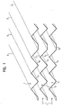
- Fig. 1 the detail of a disk set of a fin heat exchanger is shown, which will be described below using the example of an air cooler.
- the disk pack consists of a large number of disks, of which only three are shown here.
- air is passed through the finned heat exchanger, which cools at the fins 1, 3, 5.
- These are interspersed with heat transfer tubes that dissipate heat from the fins and give off to a coolant flowing in the tubes.
- the heat transfer tubes are not shown in FIG. 1 for the sake of clarity.
- up-facing teeth 9 are not necessarily all provided with a reference numeral.
- the individual lamellae are embossed.
- the embossing is periodic at least insofar that always three prongs 9 are arranged directly next to each other.
- Between the in Fig. 1 upwardly pointing serrations 9 are down-facing spikes 11.
- Only between individual up-facing spikes is a narrow horizontal Area 12 in the field of Edelstab be Replacementen 17 (see Fig. 3), for example, to facilitate the drainage of condensation from the lamella.
- FIG. 2 shows a lateral plan view of the section of the lamella block.
- FIG. The distance between two upwardly pointing serrations 9 is designated as period P.
- the spacing of the lamellae is designated A, while the embossing height, which indicates the height between an upwardly pointing and a downwardly pointing tip, is designated by PH. 13 denotes the example of the tine 10, the formation of turbulent flow, which is generated by the tearing of the flow at the top of the adjacent tine 10.
- Fig. 3 shows the top view of a lamella, here also the passages 15 for the heat transfer tubes and bushings 17 are shown for Schustabrohre.
- the heat transfer tubes 15 are guided through the heat transfer tube bushings, which are to remove heat in the described cooling operation of the slats.
- the flare-free bushings for the Schustabrohre Schustabrohre are also performed in a manner not shown, which have been pressed by internal expansion after pushing through the slats.
- By Schustabrohre 17 heating elements can be easily inserted, with the help of the lamella z. B. can be defrosted to remove frost.
- the heat transfer tubes are pressed by internal expansion in the openings of the slats.
- the heat transfer tube ducts 15 are arranged in a grid such that three adjacent heat transfer tubes form an isosceles triangle.
- the ratio of the diameter of a heat transfer tube or passage 15 to the length of a leg of the triangle is e.g. between 0.25 and 0.33.
- the Schustabrohr be arrangementen 17 are each between two heat transfer tube ducts 15th
- the design of the plate heat exchanger with serrated lamellae has proven to be particularly favorable for so-called offset systems in which the individual heat transfer tube bushings as shown in Fig. 3 are not arranged in a rectangular grid. In contrast to an aligned arrangement here the formation of a turbulent flow is further supported.
- FIG. 4 shows a side view in the viewing direction IV, as indicated in FIG. 3.
- the bushings 17 for the heating elements have no Aufbördelept.
- the flanges of the heat transfer tube bushings 15 are designated 16.
- An inventive plate heat exchanger is z. B. used as an air cooler.
- coolant is conveyed in a conventional manner.
- the air to be cooled 7 is sent between the slats through the disk pack.
- the air flow is deflected and breaks off at the tips. This results in a turbulent flow 13, which is exemplified at a tine 10 of the blade 3 in Fig. 2.
- the turbulent air flow must first rest against the lamellar surface. Heat is transferred very effectively during this approach.
- the generation of the turbulent air flow 13 prevents the formation of a laminar flow, which would be very inefficient for heat transfer, because directly on the blade itself a standing air layer would be present.
- the embossing height is selected for an air velocity of 1.5 to 3.5 m / s, for example, between 2.2 mm to 2.4 mm and the fin spacing between 3 mm and 8 mm.
- the period is chosen such that the quotient between imprint height and period lies between 0.2 and 0.25.
- the particular configuration of the lamellae according to the invention and of the lamellar heat exchanger according to the invention ensures optimal formation of turbulent flow on the lamellar surface, without the risk that, as in the prior art, slits in the lamellae are added by frost. Therefore, the system according to the invention allows effective operation over longer periods of time and reduces the necessary number of defrosting operations.
- the appropriate selection of the dimensions of the embossed lamella leads to a particularly effective heat exchange between the lamella and the flowing medium.
- the heating rod tubes or heating tubes can be compressed by widening in the openings 17. So can be achieved with compressed tubes during heating a higher fin temperature at the same time lower surface temperature of the Edelstabrohres or heating tube. As a result, undesired vapor formation on the heating rod tube or heating tube during defrosting is reduced.
Landscapes
- Engineering & Computer Science (AREA)
- Physics & Mathematics (AREA)
- Thermal Sciences (AREA)
- Mechanical Engineering (AREA)
- General Engineering & Computer Science (AREA)
- Geometry (AREA)
- Heat-Exchange Devices With Radiators And Conduit Assemblies (AREA)
Abstract
Description
- Die Erfindung betrifft eine Lamelle für einen Lamellenwärmetauscher mit mehreren parallel angeordneten Lamellen zum Wärmeaustausch mit einem seitlich an die Lamellen anströmenden gasförmigen Medium, einen Lamellenwärmetauscher mit mehreren solchen Lamellen und eine Verwendung des Lamellenwärmetauschers.
- Bei Lamellenwärmetauschern ist eine Anzahl von in der Regel metallischen Lamellen parallel zueinander angeordnet und wird von einem oder mehreren Wärmeübertragungsrohren durchsetzt. Ein Lamellenwärmetauscher wird z. B. zur Kühlung oder Erwärmung gasförmiger Medien, insbesondere von Luft eingesetzt. Ein solcher Lamellenwärmetauscher zur Kühlung gasförmiger Medien ist z. B. in DE 197 09 176 A1 beschrieben. Durch das Wärmeübertragungsrohr strömt im Kühlbetrieb ein Kühlmittel, während durch den freien Raum zwischen den Lamellen das zu kühlende Medium strömt. Das abgekühlte Wärmeübertragungsrohr kühlt die Lamellen, die wiederum Wärme von dem strömenden gasförmigen Medium übernehmen.
- Ohne besondere Maßnahmen ist die Strömung des gasförmigen Mediums im Wesentlichen laminar. Dementsprechend ist direkt an den Lamellen die Strömungsgeschwindigkeit des Mediums gleich Null oder nur sehr gering und der Wärmeübergang begrenzt.
- Ein besserer Wärmeaustausch wird durch turbulente Strömung erreicht. Bei bekannten Lösungen wird dazu die Lamelle bereichsweise geschlitzt und an den Schlitzen lappenartig nach außen gebogen. Die Strömung des gasförmigen Mediums reißt an dem Schlitz ab und muss sich als Anlaufströmung erst wieder an der Lamellenoberfläche anlegen. Gerade im Bereich dieser Anlaufströmung werden die höchsten örtlichen Wärme-übergänge erzielt. Bei Lamellenwärmetauschern, die zur Kühlung eingesetzt werden, kann sich Reif an der Lamellenoberfläche ablagern, der die Schlitze der Lamelle zusetzt. Um die Effizienz des Lamellenwärmetauschers aufrechtzuerhalten sind daher häufige Abtauvorgänge zur Entfernung des Reifs notwendig. Ebenso können sich geschlitzte Lamellen, die zur Erwärmung eines gasförmigen Mediums eingesetzt werden, mit Schmutz zusetzen. Diese Wärmetauscher müssen dann aufwendig gereinigt werden.
- Aufgabe der vorliegenden Erfindung ist es, eine Lamelle für einen Lamellenwärmetauscher und einen Lamellenwärmetauscher anzugeben, mit deren Hilfe dieser Nachteil des Standes der Technik vermieden werden kann und die einen effizienten Wärmeaustausch ermöglichen.
- Diese Aufgabe wird mit einer Lamelle mit den Merkmalen des Anspruchs 1 bzw. einem Lamellenwärmetauscher mit den Merkmalen des Anspruches 6 gelöst. Eine besonders vorteilhafte Verwendung des Lamellenwärmetauschers ist Gegenstand des Anspruches 13. Unteransprüche sind auf bevorzugte Ausgestaltungen gerichtet.
- Eine erfindungsgemäße Lamelle weist eine Prägung auf, die in Strömungsrichtung des gasförmigen Mediums ein zackenförmiges Profil hat, das derart geformt ist, dass an den Spitzen der Zacken ein Strömungsabriss zur Erzeugung eines turbulenten Strömungsmusters auftritt. Durch die Verwendung einer solchen zackenförmigen Prägung sind Schlitze in der Lamelle, die leicht mit Reif oder Schmutz zugesetzt werden können, nicht notwendig. Dennoch lässt sich mit der erfindungsgemäßen Ausgestaltung erreichen, dass die Strömung an den Spitzen der Zacken des zackenförmigen Profils abreißt und so die laminare Strömung an der Lamellenoberfläche unterbrochen wird. Es entsteht turbulente Strömung, deren Wirbel sich erst wieder an die Lamellenoberfläche anlegen müssen. Bei dieser Anlaufströmung ist der Wärmeübertrag besonders hoch.
- Das zackenförmige Profil kann unterschiedliche Ausgestaltungen haben. Besonders effektiv und einfach herstellbar ist ein zumindest bereichsweise periodisches Profil, das auch die Installation der einzelnen Lamellen eines Lamellenwärmetauschers vereinfacht.
- Bei einer besonders vorteilhaften Weiterbildung stehen die Periode P und die zwischen zwei entgegengesetzt weisenden Spitzen des zackenförmigen Profils gemessene Prägungshöhe PH in vorbestimmter Beziehung zueinander. Der Quotient zwischen Prägungshöhe und Periode liegt vorteilhafterweise zwischen 0,2 und 0,25. Dieser Bereich gewährleistet, dass die "Täler" zwischen zwei Zacken nicht derart tief sind, dass ein zu großer Totraum entsteht, in dem keine Strömung mehr auftritt. Andererseits sind die Flanken der Zacken steil genug, um den Abriss der Strömung an den Zacken zu gewährleisten.
- Besonders effizient ist ein Lamellenwärmetauscher mit erfindungsgemäßen Lamellen, wenn die Prägungshöhe PH größer als 2 mm ist, insbesondere in einem Bereich zwischen 2,2 mm und 2,4 mm. Dieses Maß für die Prägungshöhe ist gerade bei einer typischen Strömungsgeschwindigkeit des gasförmigen Mediums von 1,5 bis 3,5 m/s besonders effektiv zur Bildung turbulenter Strömung.
- Ein erfindungsgemäßer Lamellenwärmetauscher zeichnet sich durch mehrere parallel angeordnete erfindungsgemäße Lamellen aus und hat unter anderem die bereits mit Bezug zu den einzelnen Lamellen geschilderten Vorteile.
- Um den Strömungsquerschnitt zwischen zwei Lamellen in Strömungsrichtung des gasförmigen Mediums im wesentlichen konstant zu halten, ist es vorteilhaft, wenn die zackenförmigen Profile der einzelnen Lamellen des Lamellenwärmetauschers zueinander in Phase sind.
- Für eine typische Strömungsgeschwindigkeit des gasförmigen Mediums von 1,5 bis 3,5 m/s eignet sich besonders ein Lamellenabstand von 3 bis 8 mm, insbesondere in einem Bereich von zwischen 4 mm und 6 mm.
- Lamellenwärmetauscher können von Wärmeübertragungsrohren durchsetzt sein, die Wärme mit den Lamellen austauschen um diese z. B. abzukühlen. Dabei kann es sich um ein einzelnes Wärmeübertragungsrohr handeln, das z. B. schlangenförmig durch die Lamellen geführt ist oder um mehrere parallel angeordnete, individuelle Wärmeübertragungsrohre. Ebenso können einzelne Wärmeübertragungsrohre außerhalb der parallel angeordneten Lamellen durch entsprechende Verbindungen zu einem schlangenförmigen Rohr verbunden sein. Im vorliegenden Text sind diese Alternativen umfasst, wenn allgemein von Wärmeübertragungsrohren gesprochen wird.
- Die erfindungsgemäße Ausgestaltung der Lamellenform kann bei Lamellenwärmetauschern eingesetzt werden, bei denen die Wärmeübertragungsrohre in rechtwinkligem Raster oder versetzt zueinander durch die Lamellen geführt sind. Bei einer bevorzugten Ausgestaltung sind die Wärmeübertragungsrohre zueinander derart versetzt angeordnet, dass drei benachbarte Durchführungen für Wärmeübertragungsrohre ein etwa gleichschenkliges Dreieck bilden. Sowohl bei einer erfindungsgemäßen Lamelle als auch bei einem erfindungsgemäßen Lamellenwärmetauscher kann dabei das Verhältnis des Durchmessers eines Wärmeübertragungsrohres bzw. einer dafür vorgesehenen Durchführung zu der Länge eines Schenkels des Dreieckes z.B. zwischen 0,25 und 0,33 gewählt werden.
- Es können Heizvorrichtungen zum Abtauen der Lamellen vorgesehen sein. So können durch die Lamellen nicht nur Wärmeübertragungsrohre sondern auch Heizrohre, Heizstabrohre oder Heizstäbe geführt sein. Durch Heizrohre kann ein heißes Medium geschickt werden um die Lamellen abzutauen. Heizstäbe können zum selben Zweck z.B. elektrisch geheizt werden. Schließlich dienen Heizstabrohre der einfachen Einführung von Heizstäben.
- Bei einer in der Herstellung besonders günstigen Ausführungsform befinden sich die Heizstabrohre, Heizrohre oder Heizstäbe zwischen je zwei Wärmeübertragungsrohren, deren Verbindungslinie schräg zur Strömungsrichtung ist. Bei der Herstellung eines solchen Lamellenwärmetauschers kann die Lamelle in gewünschter Größe einfach geschnitten werden.
- Bei bekannten Lösungen für Lamellenwärmetauscher mit Heizrohren, Heizstabrohren bzw. Heizstäben sind die dafür in den Lamellen vorgesehenen Durchführungen an ihren Rändern aufgebördelt. Auch bei dem erfindungsgemäßen Lamellenwärmetauscher mit geprägten Lamellen und den erfindungsgemäßen Lamellen können die Durchführungen für die Heizrohre, Heizstäbe bzw. Heizstabrohre aufgebördelt sein. Um den Strömungswiderstand für das durch den Lamellenwärmetauscher strömende gasförmige Medium nicht zu hoch werden zu lassen, wird jedoch bei einer Weiterbildung der Erfindung auf die Aufbördelung verzichtet. Erstaunlicherweise wird der Wärmeübertrag dadurch nicht wesentlich verschlechtert. Um den Wärmeübertrag noch weiter zu verbessern, können bei einer Ausgestaltung mit Heizrohren oder Heizstabrohren die Rohre in den Öffnungen der Lamellen aufgeweitet werden, so dass sie in den Lamellen fest verpresst sind.
- Besonders vorteilhaft ist die Verwendung eines erfindungsgemäßen Lamellenwärmetauschers zur Kühlung, insbesondere von Luft, da es dabei besonders leicht zur Reifbildung kommen kann.
- Die Erfindung wird anhand der anliegenden Figuren im Detail erläutert. Dabei zeigt
- Fig. 1
- eine perspektivische Ansicht eines Ausschnitts aus einem Lamellenblock eines erfindungsgemäßen Lamellenwärmetauschers,
- Fig. 2
- eine seitliche Draufsicht auf einen Ausschnitt aus einem Lamellenblock der Figur 1,
- Fig. 3
- eine Draufsicht auf eine erfindungsgemäße Lamelle, und
- Fig. 4
- eine seitliche Draufsicht auf diese Lamelle in Blickrichtung IV der Fig. 3.
- In Fig. 1 ist der Ausschnitt aus einem Lamellenpaket eines Lamellenwärmetauschers gezeigt, der im Folgenden am Beispiel eines Luftkühlers beschrieben wird. Das Lamellenpaket besteht aus einer großen Anzahl Lamellen, von denen hier nur drei dargestellt sind. In Richtung 7 wird Luft durch den Lamellenwärmetauscher geströmt, die sich an den Lamellen 1, 3, 5 abkühlt. Diese sind dazu von Wärmeübertragungsrohren durchsetzt, die Wärme von den Lamellen abführen und an ein Kühlmittel abgeben, das in den Rohren fließt. Die Wärmeübertragungsrohre sind der Übersichtlichkeit halber in Fig. 1 nicht gezeigt.
- Mehrfach vorhandene Elemente, also hier z. B. nach oben weisende Zacken 9 sind nicht notwendigerweise alle mit einem Bezugszeichen versehen.
- Die einzelnen Lamellen sind zackenförmig geprägt. Im Wesentlichen ist die Prägung zumindest insofern periodisch, dass immer drei Zacken 9 direkt nebeneinander angeordnet sind. Zwischen den in Fig. 1 nach oben weisenden Zacken 9 liegen nach unten weisende Zacken 11. Nur zwischen einzelnen nach oben weisenden Zacken befindet sich ein schmaler waagerechter Bereich 12 im Bereich der Heizstabdurchführungen 17 (siehe Fig. 3), um z.B. das Ablaufen von Tauwasser von der Lamelle zu vereinfachen.
- Fig. 2 zeigt eine seitliche Draufsicht auf den Ausschnitt des Lamellenblocks. Der Abstand zweier nach oben weisender Zacken 9 ist als Periode P bezeichnet. Der Abstand der Lamellen ist mit A bezeichnet, während die Prägungshöhe, die die Höhe zwischen einer nach oben weisenden und einer nach unten weisenden Spitze angibt, mit PH bezeichnet ist. 13 bezeichnet am Beispiel der Zacke 10 die Entstehung turbulenter Strömung, die durch das Abreißen der Strömung an der Spitze der benachbarten Zacke 10 erzeugt wird.
- Fig. 3 zeigt die Draufsicht auf eine Lamelle, wobei hier auch die Durchführungen 15 für die Wärmeübertragungsrohre und Durchführungen 17 für Heizstabrohre gezeigt sind.
- In nicht gezeigter Weise sind durch die Wärmeübertragungsrohrdurchführungen 15 die Wärmeübertragungsrohre geführt, die im beschriebenen Kühlbetrieb Wärme von den Lamellen abtransportieren sollen. Durch die bördelfreien Durchführungen für die Heizstabrohre sind in ebenfalls nicht gezeigter Weise Heizstabrohre geführt, die durch inneres Aufweiten nach dem Durchschieben in den Lamellen verpresst worden sind. Durch die Heizstabrohre 17 können Heizstäbe auf einfache Weise eingeführt werden, mit deren Hilfe die Lamelle z. B. abgetaut werden kann, um Reif zu entfernen. Auch die Wärmeübertragungsrohre sind durch inneres Aufweiten in den Öffnungen der Lamellen verpresst.
- Die Wärmeübertragungsrohrdurchführungen 15 sind in einem Raster derart angeordnet, dass drei benachbarte Wärmeübertragungsrohre ein gleichschenkliges Dreieck bilden. Das Verhältnis des Durchmessers eines Wärmeübertragungsrohres bzw. einer Wärmeübertragungsrohrdurchführung 15 zu der Länge eines Schenkels des Dreieckes beträgt z.B. zwischen 0,25 und 0,33. In der gezeigten Anordnung befinden sich die Heizstabrohrdurchführungen 17 jeweils zwischen zwei Wärmeübertragungsrohrdurchführungen 15.
- Die Ausbildung des Lamellenwärmetauschers mit zackenförmig geprägten Lamellen hat sich als besonders günstig für so genannte versetzte Systeme erwiesen, in denen die einzelnen Wärmeübertragungsrohrdurchführungen wie in Fig. 3 dargestellt nicht in einem rechtwinkligen Raster angeordnet sind. Im Gegensatz zu einer fluchtenden Anordnung wird hier die Ausbildung einer turbulenten Strömung noch weiter unterstützt.
- Fig. 4 zeigt eine seitliche Ansicht in Blickrichtung IV, wie sie in Fig. 3 angedeutet ist. Hier ist insbesondere erkennbar, dass die Durchführungen 17 für die Heizstäbe keine Aufbördelungen aufweisen. Die Aufbördelungen der Wärmeübertragungsrohrdurchführungen 15 sind mit 16 bezeichnet.
- Die Heizstabrohrdurchführungen 17 unterstützen die Bildung der turbulenten Strömung. In der Regel sind nicht alle Durchführungen tatsächlich von Heizstabrohren durchsetzt. Die nicht verwendeten Heizstabrohrdurchführungen fördern den Strömungsabriss und die Bildung der turbulenten Strömung. Um den Strömungswiderstand für das durch das Lamellenpaket strömende Gas nicht zu hoch werden zu lassen, hat es sich als vorteilhaft erwiesen, wenn die Heizstabrohrdurchführungen 17 keine Randbördelung aufweisen, wie es in der seitlichen Ansicht der Fig. 4 erkennbar ist.
- Ein erfindungsgemäßer Lamellenwärmetauscher wird wie folgt z. B. als Luftkühler verwendet. Durch die in den Figuren nicht gezeigten Wärmeübertragungsrohre wird in an sich bekannter Weise Kühlmittel gefördert.
- Die zu kühlende Luft 7 wird zwischen den Lamellen durch das Lamellenpaket geschickt. An den Spitzen der Zacken 9, 10, 11 der Lamellen 1, 3, 5 wird der Luftstrom abgelenkt und reißt an den Spitzen ab. Dadurch entsteht eine turbulente Strömung 13, die beispielhaft an einer Zacke 10 der Lamelle 3 in Fig. 2 dargestellt ist. Die turbulente Luftströmung muss sich erst wieder an die Lamellenoberfläche anlegen. Bei diesem Anströmvorgang wird sehr effektiv Wärme übertragen. Die Erzeugung der turbulenten Luftströmung 13 verhindert die Ausbildung einer laminaren Strömung, die für den Wärmeübertrag sehr ineffizient wäre, weil direkt an der Lamelle selbst eine stehende Luftschicht vorhanden wäre.
- Bildet sich durch die Abkühlung der Luft Reif an der Lamelle oder den Wärmeübertragungsrohren, wird dieser mit Hilfe von durch die Heizstabrohre geführten, z. B. elektrisch beheizten Heizstäben, abgetaut.
- Die Prägungshöhe wird für eine Luftgeschwindigkeit von 1,5 bis 3,5 m/s z.B. zwischen 2,2 mm bis 2,4 mm und der Lamellenabstand zwischen 3 mm und 8 mm gewählt. Die Periode ist derart gewählt, dass der Quotient zwischen Prägungshöhe und Periode zwischen 0,2 und 0,25 liegt.
- Die besondere Ausgestaltung der erfindungsgemäßen Lamellen und des erfindungsgemäßen Lamellenwärmetauschers gewährleistet eine optimale Ausbildung von turbulenter Strömung an der Lamellenoberfläche, ohne dass die Gefahr besteht, dass wie beim Stand der Technik Schlitze in den Lamellen durch Reif zugesetzt werden. Das erfindungsgemäße System ermöglicht daher auch über längere Zeiträume einen effektiven Betrieb und verringert die notwendige Anzahl von Abtauvorgängen. Die geeignete Auswahl der Dimensionen der geprägten Lamelle führt zu einem besonders effektiven Wärmeaustausch zwischen Lamelle und strömendem Medium.
- Zur Verbesserung des Wärmeübertrages können die Heizstabrohre bzw. Heizrohre durch Aufweitung in den Öffnungen 17 verpresst sein. So kann mit verpressten Rohren während des Heizens eine höhere Lamellentemperatur bei gleichzeitig geringerer Oberflächentemperatur des Heizstabrohres bzw. Heizrohres erreicht werden. Dadurch wird eine unerwünschte Dampfbildung am Heizstabrohr bzw. Heizrohr beim Abtauen verringert.
-
- 1, 3, 5
- Lamelle
- 7
- Strömung des gasförmigen Mediums
- 9, 10, 11
- Zacken der Lamellenprägung
- 12
- waagrechte Bereiche der Lamellenprägung
- 13
- turbulente Strömung
- 15
- Durchführungen für Wärmeübertragungsrohre
- 16
- Aufbördelung
- 17
- Heizstabrohrdurchführungen
- P
- Periode der Lamellenprägung
- PH
- Prägungshöhe der Lamellenprägung
- A
- Lamellenabstand
Claims (15)
- Lamelle für einen Lamellenwärmetauscher mit mehreren parallel angeordneten Lamellen zum Wärmeaustausch mit einem seitlich an die Lamellen anströmendem gasförmigem Medium,
gekennzeichnet durch
eine Prägung, die in Strömungsrichtung (7) des gasförmigen Mediums ein zackenförmiges Profil hat, das derart geformt ist, dass an den Spitzen der Zacken (9, 10, 11) ein Strömungsabriss zur Erzeugung eines turbulenten Strömungsmusters (13) auftritt. - Lamelle nach Anspruch 1,
dadurch gekennzeichnet, dass
die zackenförmige Prägung zumindest bereichsweise in etwa periodisch ist. - Lamelle nach Anspruch 2,
dadurch gekennzeichnet, dass
die Periode P und die zwischen zwei entgegengesetzt weisenden Spitzen (9, 11) der zackenförmigen Prägung gemessene Prägungshöhe PH folgende Beziehung erfüllen:
- Lamelle nach einem der Ansprüche 1 bis 3,
dadurch gekennzeichnet, dass
die zwischen zwei entgegengesetzt weisenden Spitzen (9, 11) der zackenförmigen Prägung gemessene Prägungshöhe PH größer als 2mm ist, vorzugsweise etwa 2,2 mm bis 2,4mm beträgt. - Lamelle nach einem der Ansprüche 1 bis 4,
gekennzeichnet durch
Durchführungsöffnungen (17) für Heizrohre, Heizstäbe oder Heizstabrohre, wobei die Öffnungen keine aufgebördelten Ränder haben. - Lamellenwärmetauscher mit mehreren parallel angeordneten Lamellen (1, 3, 5) gemäß einem der Ansprüche 1 bis 5.
- Lamellenwärmetauscher nach Anspruch 6,
dadurch gekennzeichnet, dass
die Prägungen der parallel angeordneten Lamellen (1, 3, 5) in Phase sind. - Lamellenwärmetauscher nach einem der Ansprüche 6 oder 7,
dadurch gekennzeichnet, dass
der Abstand A der Lamellen 3 bis 8 mm, vorzugsweise zwischen 4 mm und 6 mm beträgt. - Lamellenwärmetauscher nach einem der Ansprüche 6 bis 8,
dadurch gekennzeichnet, dass
die Lamellen (1, 3, 5) jeweils Durchführungen für mehrere Wärmeübertragungsrohre aufweisen, die zum Wärmeaustausch mit den Lamellen dienen, wobei drei benachbarte Durchführungen (15) für Wärmeübertragungsrohre jeweils ein etwa gleichschenkliges Dreieck bilden. - Lamellenwärmetauscher nach Anspruch 9,
dadurch gekennzeichnet, dass
das Verhältnis zwischen dem Durchmesser einer Wärmeübertragungsrohrdurchführung (15) und der Länge eines Schenkels des Dreieckes zwischen 0,25 und 0,33 liegt. - Lamellenwärmetauscher nach einem der Ansprüche 9 oder 10,
dadurch gekennzeichnet, dass
die Lamellen (1, 3, 5) parallel zu den Wärmeübertragungsrohren von einem oder mehreren Heizrohren, Heizstäben oder Heizstabrohren zum Abtauen durchsetzt sind, wobei die Heizrohre, Heizstäbe oder Heizstabrohre jeweils fluchtend zwischen je zwei Wärmeübertragungsrohren (15) angeordnet sind, deren Verbindungslinie schräg zur Strömungsrichtung der gasförmigen Mediums ist. - Lamellenwärmetauscher nach Anspruch 11,
dadurch gekennzeichnet, dass
die Heizrohre, Heizstäbe oder Heizstabrohre durch Öffnungen (17) in den Lamellen (1, 3, 5) geführt sind, die keine aufgebördelten Ränder haben. - Lamellenwärmetauscher nach Anspruch 12,
dadurch gekennzeichnet, dass
Heizrohre oder Heizstabrohre vorgesehen sind, die durch Aufweitung in Öffnungen (17) der Lamellen (1, 3, 5) verpresst sind. - Verwendung eines Lamellenwärmetauschers nach einem der Ansprüche 6 bis 13 zur Kühlung oder Erwärmung eines gasförmigen Mediums.
- Verwendung nach Anspruch 14 zur Kühlung oder Erwärmung von Luft.
Applications Claiming Priority (1)
| Application Number | Priority Date | Filing Date | Title |
|---|---|---|---|
| DE102005005293A DE102005005293A1 (de) | 2005-02-04 | 2005-02-04 | Lamellenwärmetauscher und Lamelle dafür |
Publications (2)
| Publication Number | Publication Date |
|---|---|
| EP1701124A1 true EP1701124A1 (de) | 2006-09-13 |
| EP1701124B1 EP1701124B1 (de) | 2017-11-08 |
Family
ID=36579256
Family Applications (1)
| Application Number | Title | Priority Date | Filing Date |
|---|---|---|---|
| EP06001939.5A Expired - Lifetime EP1701124B1 (de) | 2005-02-04 | 2006-01-31 | Lamellenwärmetauscher |
Country Status (2)
| Country | Link |
|---|---|
| EP (1) | EP1701124B1 (de) |
| DE (1) | DE102005005293A1 (de) |
Cited By (1)
| Publication number | Priority date | Publication date | Assignee | Title |
|---|---|---|---|---|
| JP2014081101A (ja) * | 2012-10-15 | 2014-05-08 | Mitsubishi Electric Corp | 冷却器および保冷庫 |
Citations (10)
| Publication number | Priority date | Publication date | Assignee | Title |
|---|---|---|---|---|
| US2529215A (en) | 1947-11-10 | 1950-11-07 | Trane Co | Heat exchanger |
| DE1751244A1 (de) * | 1967-10-27 | 1971-06-09 | Alfa Laval Ab | Waermeaustauscher fuer den Waermeuebergang zwischen einer Fluessigkeit und einem Gas oder Luft |
| DE1751464A1 (de) | 1967-06-08 | 1971-07-15 | Air Preheater | Waermetauscher-Baugruppe |
| US4449581A (en) * | 1982-08-30 | 1984-05-22 | Chromalloy American Corporation | Heat exchanger fin element with dog-bone type pattern of corrugations |
| EP0469150A1 (de) | 1990-02-20 | 1992-02-05 | Nauchno-Proidsvodstevennoe Obiedinenie Po Traktorostroeniju | Plattenpaket für rohrwärmetauscher mit diffusor-vermenger-kanälen und rotormatrize zur herstellung der platten dieses pakets |
| WO1994027105A1 (en) | 1993-05-19 | 1994-11-24 | Norsk Hydro A.S | Mechanically assembled high internal pressure heat exchanger |
| DE19709176A1 (de) | 1997-03-06 | 1998-09-17 | Juergen Lessing | Lamellenwärmetauscher |
| US5927393A (en) * | 1997-12-11 | 1999-07-27 | Heatcraft Inc. | Heat exchanger fin with enhanced corrugations |
| US20020023744A1 (en) * | 1999-12-10 | 2002-02-28 | Kwang-Il Kim | Manufacturing method for split heat exchanger having oval tubes in zigzag pattern |
| US20040251016A1 (en) | 2003-05-28 | 2004-12-16 | Sai Kee Oh | Heat exchanger |
Family Cites Families (8)
| Publication number | Priority date | Publication date | Assignee | Title |
|---|---|---|---|---|
| DE2530064A1 (de) * | 1975-07-05 | 1977-01-27 | Volkswagenwerk Ag | Luftlamelle fuer einen leichtmetall- waermetauscher |
| EP0164340A1 (de) * | 1983-12-07 | 1985-12-18 | Licencia Talalmanyokat Ertekesitö Vallalat | Verfahren und rekuperationswärmeaustauscheinrichtung zur gewinnung von verunreinigungen aus verunreinigter warmluft, insbesondere aus rauchgasen, und zur reduktion der schornsteinkorrosion |
| DE3409608A1 (de) * | 1984-03-15 | 1985-09-19 | Klöckner-Humboldt-Deutz AG, 5000 Köln | Aus einzelnen platten zusammengesetztes netz eines kreuzstromwaermetauschers |
| DE8628175U1 (de) * | 1986-10-22 | 1986-12-18 | Thermal-Werke, Wärme-, Kälte-, Klimatechnik GmbH, 6909 Walldorf | Lamelle |
| DE3918610A1 (de) * | 1989-06-07 | 1990-12-13 | Guentner Gmbh Hans | Luftgekuehlter waermeaustauscher |
| FR2650382A1 (fr) * | 1989-07-27 | 1991-02-01 | Const Aero Navales | Echangeur a plaques a circuits etanches |
| DE19813119A1 (de) * | 1998-03-25 | 1999-10-07 | Inst Energetik Und Umwelt Ggmb | Turbulenzwärmerückgewinner und Anwendungen desselben |
| DE29916493U1 (de) * | 1999-09-14 | 2000-04-06 | FPL Wärmerückgewinnung-Lüftung GmbH, 38889 Blankenburg | Vorrichtung für den Wärmetausch im Kreuzstromprinzip |
-
2005
- 2005-02-04 DE DE102005005293A patent/DE102005005293A1/de not_active Withdrawn
-
2006
- 2006-01-31 EP EP06001939.5A patent/EP1701124B1/de not_active Expired - Lifetime
Patent Citations (10)
| Publication number | Priority date | Publication date | Assignee | Title |
|---|---|---|---|---|
| US2529215A (en) | 1947-11-10 | 1950-11-07 | Trane Co | Heat exchanger |
| DE1751464A1 (de) | 1967-06-08 | 1971-07-15 | Air Preheater | Waermetauscher-Baugruppe |
| DE1751244A1 (de) * | 1967-10-27 | 1971-06-09 | Alfa Laval Ab | Waermeaustauscher fuer den Waermeuebergang zwischen einer Fluessigkeit und einem Gas oder Luft |
| US4449581A (en) * | 1982-08-30 | 1984-05-22 | Chromalloy American Corporation | Heat exchanger fin element with dog-bone type pattern of corrugations |
| EP0469150A1 (de) | 1990-02-20 | 1992-02-05 | Nauchno-Proidsvodstevennoe Obiedinenie Po Traktorostroeniju | Plattenpaket für rohrwärmetauscher mit diffusor-vermenger-kanälen und rotormatrize zur herstellung der platten dieses pakets |
| WO1994027105A1 (en) | 1993-05-19 | 1994-11-24 | Norsk Hydro A.S | Mechanically assembled high internal pressure heat exchanger |
| DE19709176A1 (de) | 1997-03-06 | 1998-09-17 | Juergen Lessing | Lamellenwärmetauscher |
| US5927393A (en) * | 1997-12-11 | 1999-07-27 | Heatcraft Inc. | Heat exchanger fin with enhanced corrugations |
| US20020023744A1 (en) * | 1999-12-10 | 2002-02-28 | Kwang-Il Kim | Manufacturing method for split heat exchanger having oval tubes in zigzag pattern |
| US20040251016A1 (en) | 2003-05-28 | 2004-12-16 | Sai Kee Oh | Heat exchanger |
Cited By (1)
| Publication number | Priority date | Publication date | Assignee | Title |
|---|---|---|---|---|
| JP2014081101A (ja) * | 2012-10-15 | 2014-05-08 | Mitsubishi Electric Corp | 冷却器および保冷庫 |
Also Published As
| Publication number | Publication date |
|---|---|
| EP1701124B1 (de) | 2017-11-08 |
| DE102005005293A1 (de) | 2006-08-10 |
Similar Documents
| Publication | Publication Date | Title |
|---|---|---|
| DE3650658T2 (de) | Wärmetauscher | |
| DE2441652A1 (de) | Waermetauscher | |
| DE2416309A1 (de) | Waermeaustauscher fuer klimaanlagen und verfahren zu seiner herstellung | |
| DE202014105709U1 (de) | Wärmeaustauscher | |
| DE112025000088T5 (de) | Wärmetauscherlamellen und Plattenwärmetauscher | |
| EP0041653B1 (de) | Wärmeaustauschelement | |
| DE112022006802T5 (de) | Wärmetauscher und kühlkreislaufgerät mit dem wärmetauscher | |
| EP2710318A1 (de) | Lamellenwärmeübertrager | |
| EP3491323B1 (de) | Wärmetauscher mit mikrokanal-struktur oder flügelrohr-struktur | |
| EP1664655B1 (de) | Wärmetauscher | |
| DE202017102436U1 (de) | Wärmetauscher mit Mikrokanal-Struktur oder Flügelrohr-Struktur | |
| EP0268831B1 (de) | Lamelle | |
| DE102016210159A1 (de) | Rippenelement für einen Wärmeübertrager | |
| EP1701124B1 (de) | Lamellenwärmetauscher | |
| DE102009021179A1 (de) | Rippe für einen Wärmeübertrager | |
| DE60317948T2 (de) | Wärmetauscher mit Kühlrippe | |
| DE102006031676B4 (de) | Turbulenzblech, Verfahren zur Herstellung eines Turbulenzbleches und Verwendung eines Turbulenzbleches | |
| EP1398592B1 (de) | Flachrohr-Wärmeübertrager | |
| EP1691159B1 (de) | Lamellenwärmetauscher, Verfahren zu dessen Herstellung und Aufweitwerkzeug zur Durchführung des Verfahrens | |
| EP4067781B1 (de) | Kälteregister zur kaltlufterzeugung mit enteisungseinrichtung | |
| DE10360240B4 (de) | Rippe für Wärmeübertrager mit paralleler Schichtung von flachen Wärmeübertragerrohren | |
| EP0918199A2 (de) | Verdampfer | |
| DE102012007063A1 (de) | Lamellen-Rohr-Wärmetauscher mit verbesserter Wärmeübertragung | |
| EP1593536B1 (de) | Vorrichtung und Verfahren zum Trennen von Fluidströmen in einer Heizeinrichtung | |
| DE202010009815U1 (de) | Plattenwärmetauscher |
Legal Events
| Date | Code | Title | Description |
|---|---|---|---|
| PUAI | Public reference made under article 153(3) epc to a published international application that has entered the european phase |
Free format text: ORIGINAL CODE: 0009012 |
|
| AK | Designated contracting states |
Kind code of ref document: A1 Designated state(s): AT BE BG CH CY CZ DE DK EE ES FI FR GB GR HU IE IS IT LI LT LU LV MC NL PL PT RO SE SI SK TR |
|
| AX | Request for extension of the european patent |
Extension state: AL BA HR MK YU |
|
| 17P | Request for examination filed |
Effective date: 20070308 |
|
| AKX | Designation fees paid |
Designated state(s): AT BE BG CH CY CZ DE DK EE ES FI FR GB GR HU IE IS IT LI LT LU LV MC NL PL PT RO SE SI SK TR |
|
| 17Q | First examination report despatched |
Effective date: 20091016 |
|
| RAP1 | Party data changed (applicant data changed or rights of an application transferred) |
Owner name: GEA KUEBA GMBH |
|
| RAP1 | Party data changed (applicant data changed or rights of an application transferred) |
Owner name: KELVION REFRIGERATION GMBH |
|
| STAA | Information on the status of an ep patent application or granted ep patent |
Free format text: STATUS: EXAMINATION IS IN PROGRESS |
|
| GRAP | Despatch of communication of intention to grant a patent |
Free format text: ORIGINAL CODE: EPIDOSNIGR1 |
|
| STAA | Information on the status of an ep patent application or granted ep patent |
Free format text: STATUS: GRANT OF PATENT IS INTENDED |
|
| INTG | Intention to grant announced |
Effective date: 20170522 |
|
| GRAS | Grant fee paid |
Free format text: ORIGINAL CODE: EPIDOSNIGR3 |
|
| GRAA | (expected) grant |
Free format text: ORIGINAL CODE: 0009210 |
|
| STAA | Information on the status of an ep patent application or granted ep patent |
Free format text: STATUS: THE PATENT HAS BEEN GRANTED |
|
| AK | Designated contracting states |
Kind code of ref document: B1 Designated state(s): AT BE BG CH CY CZ DE DK EE ES FI FR GB GR HU IE IS IT LI LT LU LV MC NL PL PT RO SE SI SK TR |
|
| REG | Reference to a national code |
Ref country code: GB Ref legal event code: FG4D Free format text: NOT ENGLISH |
|
| REG | Reference to a national code |
Ref country code: CH Ref legal event code: EP Ref country code: AT Ref legal event code: REF Ref document number: 944535 Country of ref document: AT Kind code of ref document: T Effective date: 20171115 |
|
| REG | Reference to a national code |
Ref country code: IE Ref legal event code: FG4D Free format text: LANGUAGE OF EP DOCUMENT: GERMAN |
|
| REG | Reference to a national code |
Ref country code: DE Ref legal event code: R096 Ref document number: 502006015719 Country of ref document: DE |
|
| REG | Reference to a national code |
Ref country code: CH Ref legal event code: NV Representative=s name: AMMANN PATENTANWAELTE AG BERN, CH |
|
| REG | Reference to a national code |
Ref country code: FR Ref legal event code: PLFP Year of fee payment: 13 |
|
| REG | Reference to a national code |
Ref country code: NL Ref legal event code: FP |
|
| REG | Reference to a national code |
Ref country code: LT Ref legal event code: MG4D |
|
| PG25 | Lapsed in a contracting state [announced via postgrant information from national office to epo] |
Ref country code: SE Free format text: LAPSE BECAUSE OF FAILURE TO SUBMIT A TRANSLATION OF THE DESCRIPTION OR TO PAY THE FEE WITHIN THE PRESCRIBED TIME-LIMIT Effective date: 20171108 Ref country code: LT Free format text: LAPSE BECAUSE OF FAILURE TO SUBMIT A TRANSLATION OF THE DESCRIPTION OR TO PAY THE FEE WITHIN THE PRESCRIBED TIME-LIMIT Effective date: 20171108 Ref country code: ES Free format text: LAPSE BECAUSE OF FAILURE TO SUBMIT A TRANSLATION OF THE DESCRIPTION OR TO PAY THE FEE WITHIN THE PRESCRIBED TIME-LIMIT Effective date: 20171108 Ref country code: FI Free format text: LAPSE BECAUSE OF FAILURE TO SUBMIT A TRANSLATION OF THE DESCRIPTION OR TO PAY THE FEE WITHIN THE PRESCRIBED TIME-LIMIT Effective date: 20171108 |
|
| PG25 | Lapsed in a contracting state [announced via postgrant information from national office to epo] |
Ref country code: GR Free format text: LAPSE BECAUSE OF FAILURE TO SUBMIT A TRANSLATION OF THE DESCRIPTION OR TO PAY THE FEE WITHIN THE PRESCRIBED TIME-LIMIT Effective date: 20180209 Ref country code: BG Free format text: LAPSE BECAUSE OF FAILURE TO SUBMIT A TRANSLATION OF THE DESCRIPTION OR TO PAY THE FEE WITHIN THE PRESCRIBED TIME-LIMIT Effective date: 20180208 Ref country code: IS Free format text: LAPSE BECAUSE OF FAILURE TO SUBMIT A TRANSLATION OF THE DESCRIPTION OR TO PAY THE FEE WITHIN THE PRESCRIBED TIME-LIMIT Effective date: 20180308 Ref country code: LV Free format text: LAPSE BECAUSE OF FAILURE TO SUBMIT A TRANSLATION OF THE DESCRIPTION OR TO PAY THE FEE WITHIN THE PRESCRIBED TIME-LIMIT Effective date: 20171108 |
|
| PG25 | Lapsed in a contracting state [announced via postgrant information from national office to epo] |
Ref country code: SK Free format text: LAPSE BECAUSE OF FAILURE TO SUBMIT A TRANSLATION OF THE DESCRIPTION OR TO PAY THE FEE WITHIN THE PRESCRIBED TIME-LIMIT Effective date: 20171108 Ref country code: EE Free format text: LAPSE BECAUSE OF FAILURE TO SUBMIT A TRANSLATION OF THE DESCRIPTION OR TO PAY THE FEE WITHIN THE PRESCRIBED TIME-LIMIT Effective date: 20171108 Ref country code: CY Free format text: LAPSE BECAUSE OF FAILURE TO SUBMIT A TRANSLATION OF THE DESCRIPTION OR TO PAY THE FEE WITHIN THE PRESCRIBED TIME-LIMIT Effective date: 20171108 Ref country code: DK Free format text: LAPSE BECAUSE OF FAILURE TO SUBMIT A TRANSLATION OF THE DESCRIPTION OR TO PAY THE FEE WITHIN THE PRESCRIBED TIME-LIMIT Effective date: 20171108 Ref country code: CZ Free format text: LAPSE BECAUSE OF FAILURE TO SUBMIT A TRANSLATION OF THE DESCRIPTION OR TO PAY THE FEE WITHIN THE PRESCRIBED TIME-LIMIT Effective date: 20171108 |
|
| REG | Reference to a national code |
Ref country code: DE Ref legal event code: R097 Ref document number: 502006015719 Country of ref document: DE |
|
| PG25 | Lapsed in a contracting state [announced via postgrant information from national office to epo] |
Ref country code: PL Free format text: LAPSE BECAUSE OF FAILURE TO SUBMIT A TRANSLATION OF THE DESCRIPTION OR TO PAY THE FEE WITHIN THE PRESCRIBED TIME-LIMIT Effective date: 20171108 Ref country code: RO Free format text: LAPSE BECAUSE OF FAILURE TO SUBMIT A TRANSLATION OF THE DESCRIPTION OR TO PAY THE FEE WITHIN THE PRESCRIBED TIME-LIMIT Effective date: 20171108 |
|
| PLBE | No opposition filed within time limit |
Free format text: ORIGINAL CODE: 0009261 |
|
| STAA | Information on the status of an ep patent application or granted ep patent |
Free format text: STATUS: NO OPPOSITION FILED WITHIN TIME LIMIT |
|
| 26N | No opposition filed |
Effective date: 20180809 |
|
| REG | Reference to a national code |
Ref country code: IE Ref legal event code: MM4A |
|
| REG | Reference to a national code |
Ref country code: BE Ref legal event code: MM Effective date: 20180131 |
|
| PG25 | Lapsed in a contracting state [announced via postgrant information from national office to epo] |
Ref country code: BE Free format text: LAPSE BECAUSE OF NON-PAYMENT OF DUE FEES Effective date: 20180131 Ref country code: SI Free format text: LAPSE BECAUSE OF FAILURE TO SUBMIT A TRANSLATION OF THE DESCRIPTION OR TO PAY THE FEE WITHIN THE PRESCRIBED TIME-LIMIT Effective date: 20171108 |
|
| PG25 | Lapsed in a contracting state [announced via postgrant information from national office to epo] |
Ref country code: IE Free format text: LAPSE BECAUSE OF NON-PAYMENT OF DUE FEES Effective date: 20180131 |
|
| PG25 | Lapsed in a contracting state [announced via postgrant information from national office to epo] |
Ref country code: TR Free format text: LAPSE BECAUSE OF FAILURE TO SUBMIT A TRANSLATION OF THE DESCRIPTION OR TO PAY THE FEE WITHIN THE PRESCRIBED TIME-LIMIT Effective date: 20171108 |
|
| PG25 | Lapsed in a contracting state [announced via postgrant information from national office to epo] |
Ref country code: PT Free format text: LAPSE BECAUSE OF FAILURE TO SUBMIT A TRANSLATION OF THE DESCRIPTION OR TO PAY THE FEE WITHIN THE PRESCRIBED TIME-LIMIT Effective date: 20171108 Ref country code: HU Free format text: LAPSE BECAUSE OF FAILURE TO SUBMIT A TRANSLATION OF THE DESCRIPTION OR TO PAY THE FEE WITHIN THE PRESCRIBED TIME-LIMIT; INVALID AB INITIO Effective date: 20060131 |
|
| PGFP | Annual fee paid to national office [announced via postgrant information from national office to epo] |
Ref country code: NL Payment date: 20240119 Year of fee payment: 19 |
|
| PGFP | Annual fee paid to national office [announced via postgrant information from national office to epo] |
Ref country code: LU Payment date: 20240119 Year of fee payment: 19 |
|
| PGFP | Annual fee paid to national office [announced via postgrant information from national office to epo] |
Ref country code: AT Payment date: 20240122 Year of fee payment: 19 |
|
| PGFP | Annual fee paid to national office [announced via postgrant information from national office to epo] |
Ref country code: MC Payment date: 20240123 Year of fee payment: 19 |
|
| PGFP | Annual fee paid to national office [announced via postgrant information from national office to epo] |
Ref country code: GB Payment date: 20240123 Year of fee payment: 19 Ref country code: CH Payment date: 20240202 Year of fee payment: 19 |
|
| PGFP | Annual fee paid to national office [announced via postgrant information from national office to epo] |
Ref country code: IT Payment date: 20240129 Year of fee payment: 19 Ref country code: FR Payment date: 20240124 Year of fee payment: 19 |
|
| PGFP | Annual fee paid to national office [announced via postgrant information from national office to epo] |
Ref country code: DE Payment date: 20250327 Year of fee payment: 20 |
|
| REG | Reference to a national code |
Ref country code: CH Ref legal event code: PL |
|
| REG | Reference to a national code |
Ref country code: NL Ref legal event code: MM Effective date: 20250201 |
|
| PG25 | Lapsed in a contracting state [announced via postgrant information from national office to epo] |
Ref country code: MC Free format text: LAPSE BECAUSE OF NON-PAYMENT OF DUE FEES Effective date: 20250131 Ref country code: LU Free format text: LAPSE BECAUSE OF NON-PAYMENT OF DUE FEES Effective date: 20250131 |
|
| REG | Reference to a national code |
Ref country code: AT Ref legal event code: MM01 Ref document number: 944535 Country of ref document: AT Kind code of ref document: T Effective date: 20250131 |
|
| GBPC | Gb: european patent ceased through non-payment of renewal fee |
Effective date: 20250131 |
|
| PG25 | Lapsed in a contracting state [announced via postgrant information from national office to epo] |
Ref country code: NL Free format text: LAPSE BECAUSE OF NON-PAYMENT OF DUE FEES Effective date: 20250201 |
|
| PG25 | Lapsed in a contracting state [announced via postgrant information from national office to epo] |
Ref country code: GB Free format text: LAPSE BECAUSE OF NON-PAYMENT OF DUE FEES Effective date: 20250131 |
|
| PG25 | Lapsed in a contracting state [announced via postgrant information from national office to epo] |
Ref country code: FR Free format text: LAPSE BECAUSE OF NON-PAYMENT OF DUE FEES Effective date: 20250131 Ref country code: AT Free format text: LAPSE BECAUSE OF NON-PAYMENT OF DUE FEES Effective date: 20250131 |
|
| PG25 | Lapsed in a contracting state [announced via postgrant information from national office to epo] |
Ref country code: CH Free format text: LAPSE BECAUSE OF NON-PAYMENT OF DUE FEES Effective date: 20250131 |
|
| PG25 | Lapsed in a contracting state [announced via postgrant information from national office to epo] |
Ref country code: IT Free format text: LAPSE BECAUSE OF NON-PAYMENT OF DUE FEES Effective date: 20250131 |
|
| REG | Reference to a national code |
Ref country code: DE Ref legal event code: R071 Ref document number: 502006015719 Country of ref document: DE |