EP1699720B1 - Solid roll provided with at least one adapter and adapter for a solid roll - Google Patents
Solid roll provided with at least one adapter and adapter for a solid roll Download PDFInfo
- Publication number
- EP1699720B1 EP1699720B1 EP04809226A EP04809226A EP1699720B1 EP 1699720 B1 EP1699720 B1 EP 1699720B1 EP 04809226 A EP04809226 A EP 04809226A EP 04809226 A EP04809226 A EP 04809226A EP 1699720 B1 EP1699720 B1 EP 1699720B1
- Authority
- EP
- European Patent Office
- Prior art keywords
- adapter
- solid roll
- attachment
- roll
- dispenser
- Prior art date
- Legal status (The legal status is an assumption and is not a legal conclusion. Google has not performed a legal analysis and makes no representation as to the accuracy of the status listed.)
- Not-in-force
Links
Images


Classifications
-
- B—PERFORMING OPERATIONS; TRANSPORTING
- B65—CONVEYING; PACKING; STORING; HANDLING THIN OR FILAMENTARY MATERIAL
- B65H—HANDLING THIN OR FILAMENTARY MATERIAL, e.g. SHEETS, WEBS, CABLES
- B65H16/00—Unwinding, paying-out webs
- B65H16/02—Supporting web roll
- B65H16/06—Supporting web roll both-ends type
Definitions
- the present invention relates to a solid roll of flexible web-shaped material, such as paper or non-woven material, provided with at least one adapter, which solid roll is suited for installation and holding in various types of conventional dispensers and is ready to be loaded in a dispenser at delivery to the end consumer without the need of adding and fitting any extra adaptation parts. Furthermore, the invention relates to an adapter for a solid roll, an adapter combination for a solid roll and a dispenser for holding a solid roll according to the invention.
- the cored roll which traditionally has been utilized, is typically produced on a hollow cylindrical core, around which the flexible web-shaped material is rolled up.
- the hollow cylindrical core may be made of some type of cardboard or plastic material. After finished production, the hollow cylindrical core remains in the cored roll.
- the cored roll intended for the end consumer comprises the hollow cylindrical core defining a hollow space at the centre of the roll.
- the coreless roll which has been introduced by new market trends, does not comprise any hollow cylindrical core around which the flexible web-shaped material is wound.
- the coreless roll comprises an opening extending through the centre of the roll.
- the coreless roll is produced on some type of mandrel belonging to the production equipment.
- the flexible web-shaped material is rolled up around the mandrel to form the roll and the mandrel is subsequently extracted and recycled after finished up-rolling.
- an opening is created through the roll.
- the opening may collapse and assume a deformed shape, such as oval, flattened or star-shaped, during or after withdrawal of the mandrel, but the coreless roll intended for the end consumer still comprises an opening at the centre of the roll.
- the innermost windings of web-shaped material are normally attached to each other by addition of some water in order to act like a core.
- the central opening of the coreless roll is much smaller in diameter than the diameter of the core of the cored roll.
- the coreless roll may comprise more flexible web-shaped material than the cored roll for a given outer diameter.
- a machine and method for the production of coreless rolls are, for example, described in EP 1268330 .
- the solid roll which has been introduced recently on the market, does not comprise any hollow cylindrical core and neither any opening extending through the centre of the roll.
- the solid roll is not produced on any core, mandrel or the like, but even the innermost part of the roll is filled with flexible web-shaped material during production of the roll.
- the finished solid roll takes on the appearance of a compact cylinder completely filled with flexible web-shaped material and is essentially homogenous in a cross-section viewed from the side.
- the density range of the solid roll is 140 -380 kg/m 3 . However, there may be some deviation from the homogenous characteristic due to, for example, technical reasons during manufacturing or due to that a deviation is desired in the centre area.
- the density range of a centre part having a diameter of 10 mm may, for example, be between 20 kg/m 3 less than the other parts of the roll and 20 kg/m 3 more than the other parts of the roll.
- the density of the centre part having a diameter of 10 mm may be measured by unwinding a solid roll such that the remaining part of the solid roll has a diameter of 10 mm and thereafter measuring the volume and weight of the remaining part of the solid roll. Since the solid roll does not have any core or opening at the centre of the roll, the solid roll may comprise more meters of flexible web-shaped material for a given outer diameter compared to the cored and coreless rolls.
- a machine and method for the production of solid rolls are, for example, described in EP 0580561 .
- cored rolls has to be taken away and discarded when all flexible web-shaped material has been used.
- the coreless and solid rolls are more environment friendly than the cored roll since all flexible web-shaped material of the coreless or solid rolls may be used and since they have no core that has to be discarded.
- cored rolls are more expensive to manufacture than coreless and solid rolls because of the expense of producing the cores and joining the product to the core.
- conventional dispensers used by consumers today are generally suited for cored rolls only.
- Many conventional dispensers comprise, for example, a spindle or the like on which the roll is to be mounted in a manner similar to ubiquitous bathroom toilet roll dispensers.
- a spindle is arranged to pass through or otherwise penetrate the inner space of the core of the cored roll such that the cored roll may rotate around the spindle.
- the spindle may be a member of the dispenser being affixed to the dispenser at one end or may be a releasable member of the dispenser being adapted to be inserted into slots, pathways or the like defined in the sides of the dispenser.
- One way to enable installation and holding in a dispenser of a coreless roll or a solid roll, respectively, is to utilize a dispenser that is specifically configured during its manufacture for loading coreless and/or solid rolls.
- One example of a type of dispenser that is specifically configured for holding coreless or solid rolls, respectively, is a disperser having the shape of a trough in which the roll is put.
- the flexible web-shaped material is fed over the upper edge of the trough or through a slit in the lower part.
- a dispenser that comprises a projection part on at least one dispenser side.
- the projection part may be a pin or the like.
- the projection part When a new solid roll is loaded in such a dispenser, the projection part is forced to penetrate between windings of the solid roll.
- the projection part In order to be able to use as much as possible of the material of the solid roll, the projection part must be forced to penetrate at or near the innermost winding.
- the user has to try to fit the solid roll to the projection part such that it penetrates at or near the innermost winding. Furthermore, it is required that some force is applied for the penetration.
- Another way to enable installation and holding in a dispenser of a coreless roll or a solid roll, respectively, is to adapt an existing dispenser for cored rolls for loading coreless or solid rolls, respectively, and/or to adapt coreless or solid rolls, respectively, to fit to such a dispenser.
- One way, which is well-known in the art, of adapting a coreless or solid roll for installation and holding in a dispenser for cored rolls comprises creation of a depression in each vertical side of a coreless roll or a solid roll, respectively, at the time of production and provision of an adapter that fits both into the depression and to a mounting structure of the dispenser.
- a method of producing a depression in a vertical side of a roll is, for example, disclosed in US 5,620,148 .
- WO 99/60909 discloses an adapter for converting a dispenser for a small cored roll into a dispenser for a small coreless roll.
- the adapter comprises a plunger arranged to extend from one of the sides of the dispenser and fit into a depression in a side of a coreless roll.
- the adapter comprises attachment means for securing the adapter to a core roll product dispenser.
- a depression is preferably provided in each side of the coreless roll at the time of production.
- US 6,082,664 discloses an adapter for small solid or coreless rolls of paper material, in which rolls there are recesses or divots defined in the vertical sides of the rolls.
- the adapter is to be placed in a dispenser for cored rolls, in which dispenser there are slots defined in the sides of the dispenser.
- the recesses which should be formed at the time of production, define a rotating axis for the coreless or solid roll and a protrusion extending from the adapter is arranged to be pressed into one of the recesses.
- An engaging member may extend substantially transverse from the adapter and may be insertable into and slidable along the slots in the sides of the dispenser.
- a pair of adapters may engage and hold the roll therebetween within the dispenser.
- US 6,592,068 discloses an adapter for small solid or coreless rolls of paper material, in which rolls there are recesses or divots defined in the vertical sides of the rolls.
- the adapter is to be placed in a dispenser for cored rolls, in which dispenser there are slots defined in the sides of the dispenser.
- the adapter includes a carriage having opposite side members attached to a transverse support arm.
- a protrusion is formed on one side of each side member, which protrusion is intended to at least partially engage into the recess in a vertical side of the solid or coreless roll.
- a pin is disposed on the other side of each side member and is intended to engage in one of the slots in the sides of the dispenser.
- Another way, which is known in the art, of adapting a coreless roll having a central aperture for loading in a dispenser for cored rolls comprises utilization of an adapter that is intended to be inserted into the aperture and to be attached to such a dispenser.
- US 5,495,997 discloses a support spindle apparatus, which is intended to be inserted into the central aperture of a coreless toilet tissue roll to support the coreless roll in a toilet tissue dispenser cabinet of the type having opposed, elongated, generally vertically oriented guide slots.
- the support spindle apparatus comprises an elongated spindle body having a generally cruciform cross-section over most of its length. In use, the spindle apparatus is inserted into the aperture of a coreless roll such that one end is positioned outside the roll on one side of the roll and the other end is positioned outside the roll on the opposite side of the roll.
- the support spindle apparatus further comprises a roll stop element fixedly attached to the elongated spindle body to prevent movement of the roll relative to the spindle apparatus in a single direction.
- US 5,868,342 describes a roll spindle intended to be used in modification of a multi-roll dispenser normally used to dispense tissue from rolls of toilet tissue having centre cores to dispense tissue from coreless rolls.
- One spindle is inserted into each roll in the multi-roll dispenser.
- the spindle comprises a spindle shaft and a plurality of roll engagement elements rotatably journaled on the spindle shaft.
- the spindle has a tapered distal end and the spindle is inserted into a roll with the tapered end first.
- a mounting member is provided for affixing the spindle to the dispenser.
- the coreless roll may be rotated around the spindle shaft by means of the rotatably journaled roll engagement members, whereas the spindle shaft is fixed in position, i.e. not rotated.
- the solid roll is provided with one adapter on each of the two sides.
- the solid roll is provided with two adapters, whereby the first attachment means of the two adapters, respectively, comprises different numbers of elongated attachment members.
- the solid roll is provided with a first adapter on one side and a second adapter on the opposite side, whereby the first attachment means of the first adapter comprises one elongated attachment member adapted to be arranged in or near the centre line of the solid roll and whereby the first attachment means of the second adapter comprises at least three elongated attachment members extending parallel to each other, which at least three elongated attachment members are arranged circumferentially and are adapted to be arranged near the centre line of the solid roll to encircle the centre line of the solid roll, and whereby the first adapter and the second adapter are adapted to be arranged such that the elongated attachment members of the second adapter encircle the elongated attachment member of the first adapter in at least a centre area of the solid roll.
- the solid roll is provided with a first adapter on one side and a second adapter on the opposite side, whereby the second attachment means of the first adapter is a recess extending into the first attachment means, which recess is adapted to be arranged to receive a shaft affixed to a dispenser or rotatably mounted to a dispenser, and whereby the second attachment means of the second adapter is a shaft, which is adapted to be arranged extending away from the solid roll and to be rotatably mounted to a dispenser.
- the solid roll is a jumbo roll, weighing at least 500 g and preferably at least 800 g.
- the solid roll is a jumbo roll, weighing at least 1000 g.
- Another object of the present invention is to provide an adapter for a solid roll for simplifying and improving the installation and holding of a solid roll in a dispenser.
- the adapter is used for jumbo rolls, weighing at least 500 g and preferably at least 800 g.
- the adapter is used for jumbo rolls, weighing at least 1000 g.
- the adapter further comprises restriction means for restricting insertion of the adapter into the solid roll, the restriction means comprising a first side being adapted to be arranged facing and adjacent to one side of the solid roll and an opposite second side adapted to be arranged facing away from the one side of the solid roll, whereby the first attachment means for attachment to the solid roll is arranged extending from the first side of the restriction means and whereby the second attachment means for attachment to a dispenser is arranged extending from the second side of the restriction means.
- the first attachment means comprises one elongated attachment member adapted to be arranged extending in or near the centre line of the solid roll, whereby the elongated attachment member comprises a helical winding.
- the first attachment means comprises at least three elongated attachment members extending parallel to each other, which at least three elongated attachment members are arranged circumferentially and are adapted to be arranged extending near the centre line of the solid roll to encircle the centre line of the solid roll.
- the first attachment means comprises one centred elongated attachment member and at least two elongated attachment members extending parallel to the centred elongated attachment member and at a distance from the centred elongated attachment member.
- the second attachment means is adapted to be arranged extending in the direction of the centre line of the solid roll.
- the second attachment means comprises a shaft, which is adapted to be arranged extending away from the solid roll and to be rotatably mounted to a dispenser.
- the adapter further comprises restriction means for restricting insertion of the adapter into the solid roll, the restriction means comprising a first side being adapted to be arranged facing and adjacent to one side of the solid roll and an opposite second side adapted to be arranged facing away from the one side of the solid roll, whereby the second attachment means is a recess extending into the restriction means, which recess is adapted to be arranged to receive a shaft affixed to a dispenser or rotatably mounted to a dispenser.
- the second attachment means is a recess extending from an end of the adapter being arranged to face a dispenser and in the direction of the first attachment means, which recess is adapted to be arranged to receive a shaft affixed to a dispenser or rotatably mounted to a dispenser.
- the second attachment means comprises a shaft, which is adapted to be arranged extending away from the solid roll and to be rotatably mounted to a dispenser, and an attachment member attached to an end of the shaft adapted to be arranged adjacent or in a dispenser, which attachment member is adapted to be arranged running parallel to said one side of the solid roll.
- the second attachment means comprises an attachment member adapted to be arranged running parallel to said one side of the solid roll, whereby said attachment member is a plate-like member.
- the adapter is a screw.
- the present invention further refers to a dispenser, which is arranged to hold a solid roll according to the invention by having complementary means being complementary to the second attachment means.
- the present invention also refers to an adapter combination comprising a first adapter and a second adapter according to the invention, whereby the first attachment means of the first adapter and the second adapter, respectively, comprises different numbers of elongated attachment members.
- the present invention further refers to an adapter combination
- a first adapter according to the invention in which the first attachment means comprises one elongated attachment member adapted to be arranged extending in or near the centre line of the solid roll and a second adapter according to the invention in which the first attachment means comprises at least three elongated attachment members extending parallel to each other, which at least three elongated attachment members are arranged circumferentially and are adapted to be arranged extending near the centre line of the solid roll to encircle the centre line of the solid roll, wherein the first adapter and the second adapter are adapted to be arranged such that the elongated attachment members of the second adapter encircle the elongated attachment member of the first adapter in at least a centre area of the solid roll.
- the present invention also refers to an adapter combination
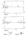
- Figures 1a and 1b show a simplified cross-sectional view of a first embodiment and a second embodiment, respectively, of a solid roll 1 of flexible web-shaped material according to the present invention, in which views the outline of the solid rolls 1 is shown with dashed lines.
- solid rolls of flexible web-shaped material do not comprise any hollow cylindrical core as cored rolls and neither any aperture extending through the centre of the roll as coreless rolls. Instead, the innermost part of solid rolls is filled with flexible web-shaped material.
- the solid roll 1 according to the invention may be of any types and sizes, including jumbo rolls.
- the solid roll 1 being cylinder-shaped, has two opposite sides 2, 3, an envelope surface 4 between the two sides 2, 3 and a centre line 5. If the solid roll 1 is wound properly and essentially evenly of flexible web-shaped material, the innermost winding is essentially located at the centre line 5. Usually, solid rolls are properly and essentially evenly wound of flexible web-shaped material and therefore the innermost winding is essentially located at the centre line 5 or at least near the centre line 5.
- the solid roll 1 is provided with at least one adapter 6, which adapter 6 is adapted to be arranged on one of the sides 2, 3.
- the solid roll 1 may be provided with one adapter 6 only, i.e. one adapter 6 on one of the sides 2, 3, or with two adapters 6, i.e. with one adapter 6 on each of the two sides 2, 3.
- the solid roll 1 is provided with one adapter 6 only.
- the solid roll 1 is provided with two adapters 6.
- the adapter 6 in the first embodiment and the adapters 6 in the second embodiment all have the same configuration.
- a first and second end view of the adapter 6 in the first and second embodiments are, respectively, shown in fig. 1c and fig. 1d .
- the solid roll 1 is, however, provided with two adapters 6 having different configurations. This will be further described below.
- the adapter 6 is adapted to be partly inserted into the solid roll 1 and comprises first attachment means 7 for attachment to the solid roll 1 and second attachment means 8 for attachment to a dispenser.
- the first attachment means 7 for attachment of the adapter 6 to the solid roll 1 is adapted to be arranged extending into the solid roll from one side 2, 3 of the solid roll 1 and is adapted to engage the solid roll 1 in or near its centre line 5.
- the second attachment means 8 for attachment of the adapter 6 to a dispenser is adapted to be arranged enabling attachment to a dispenser.
- the second attachment means 8 is adapted to be arranged extending in the direction of the centre line 5 of the solid roll 1.
- the second attachment means 8 is adapted to allow attachment of the adapter 6 to various types of conventional dispensers including conventional dispensers for cored rolls as well as dispensers intended for solid and coreless rolls being provided with depressions in their sides.
- the second attachment means 8 comprises a shaft 13, which is adapted to be arranged extending away from the solid roll 1 and to be rotatably mounted to complementary means in a dispenser. Examples of complementary means in a dispenser to which the shaft 13 may be mounted are different types of bearings.
- the shape of the second attachment means 8 may be varied in further embodiments in order to fit to different complementary means in different types of conventional dispensers. In some cases it might also be possible to change the complementary means in a conventional dispenser in order to fit to the second attachment means 8.
- the first attachment means 7 of the adapter 6 in the first and second embodiments comprises one elongated attachment member 9, which for example has the shape of a pin, tube or the like and which is adapted to be arranged extending in or near the centre line 5 of the solid roll 1.
- the elongated attachment member 9 is adapted to fixate the adapter 6 to the flexible web-shaped material of the solid roll 1 through frictional engagement.
- the adapter 6 may in other embodiments of the solid roll 1 comprise more than one elongated attachment member 9.
- Other embodiments of the present invention, in which the adapter 6 comprises more than one elongated attachment member 9 adapted to be arranged to extend in or near the centre line of the solid roll 1 will be further described below.
- the elongated attachment member 9 is adapted to be inserted into the solid roll 1 between windings of flexible web-shaped material since even the innermost part of the solid roll 1 is filled with material. If the solid roll 1 is essentially evenly wound with flexible web-shaped material, which it usually is, then the centre line 5 of the solid roll 1 coincides at least essentially with the rotational axis of the solid roll 1. However, after insertion of the elongated attachment member 9 into the solid roll 1, the second attachment means 8 defines a rotational centre line 10 for the solid roll 1, around which the solid roll 1 will rotate when held in a dispenser.
- the elongated attachment member 9 is inserted in or near the innermost winding. Since solid rolls usually are properly and essentially evenly wound of flexible web-shaped material, and the innermost winding therefore is essentially located at the centre line 5 or at least near the centre line 5, it is important that the elongated attachment member 9 is inserted in or near the centre line 5 of the solid roll 1.
- the elongated attachment member 9 is preferably inserted essentially along the centre line 5 of the solid roll 1 and most preferably along the centre line 5 of the solid roll 1.
- the elongated attachment member 9 Since even the innermost part of the solid roll 1 is filled with material, the elongated attachment member 9 must be forced to penetrate into the solid roll 1.
- the elongated attachment member 9 comprises a portion 12 with a tapered shape ending in a pointed distal end 11 in order to facilitate the penetration of the elongated attachment member 9 into the solid roll 1.
- the portion 12 having a tapered shape may constitute only a part of the elongated attachment member 9 or the complete elongated attachment member 9.
- the tapering of the portion 12 having a tapered shape may be gradual or stepwise to the pointed distal end 11.
- the adapter 6 is inserted with the pointed distal end 11 first, which may be sharply pointed.
- the elongated attachment member 9 does not comprise a tapered portion 12 nor a pointed distal end 11. Furthermore, in still other embodiments comprising more than one elongated attachment member 9, only one or some of the elongated attachment members 9 comprise a tapered portion 12 and a pointed distal end 11.
- the pointed distal end 11 and the tapered portion 12 ease insertion of the elongated attachment member 9 and reduce the force required for insertion. Nevertheless, the insertion of the elongated attachment member 9 requires that a relatively high pressure is applied. Furthermore, at insertion of the elongated attachment member 9 of the adapter 6 into the solid roll 1 it is important, as above described, that the elongated attachment member 9 is inserted near or in the centre line of the solid roll 1 in order to be able to unwind and use essentially all flexible web-shaped material.
- the insertion of the adapter 6 is preferably performed at the time of manufacture of the solid roll 1 or at least before the solid roll 1 reaches the end consumer. By performing the insertion of the adapter 6 at a factory, the insertion may be performed under controlled circumstances.
- a force that is high enough, but not too high, may then be applied for the insertion of the adapter 6 into the solid roll 1, suitable means may be applied for the insertion and the insertion may be controlled to be performed such that the elongated attachment member 9 is inserted in or near the centre line of the solid roll 1.
- a kit with the solid roll 1 provided with one or two adapters 6 may be delivered to the end consumer. This implies that the solid roll 1 is ready for use at delivery, i.e. that the user does not have to apply any adapter(s) before loading in a dispenser.
- the end consumer does not have to deal with the difficulties concerning insertion of the adapter(s) 6 into the solid roll 1, concerning fitting of the adapter(s) 6 such that the adapter(s) 6 is/are inserted in or near the centre line of the solid roll and, if two adapters 6 are to be used, concerning alignment of the two adapters 6.
- the elongated attachment member 9 has a circular cross-section, but the cross-section may also have other shapes, such as for example oval, triangular, rectangular or star-shaped.
- the elongated attachment member 9 could also have a central body with a plurality of pins protruding from it. The length and the diameter of the elongated attachment member 9 must be suited for holding the solid roll 1 securely and for delaying collapse when there are only a few windings left of material of the solid roll 1.
- the adapter 6 is produced of a metal, such as steel, aluminium alloys etc. However, other materials like for example plastic materials or pressed wood may also be used.
- the adapter 6 is relatively easy to produce and may be produced at a relatively low material cost.
- the adapter 6 is preferably disposable, but may also be non-disposable.
- the adapter 6 in the first and the second embodiments of the solid roll 1 has, as may be seen in figs. 1a-1d , the shape of a pin or the like, whereby one end part constitutes the first attachment means 7 and the other end part constitutes the second attachment means 8.
- the end part constituting the first attachment means 7 must then be positioned within the solid roll 1 such that reliable attachment of the adapter 6 to the solid roll 1 is achieved.
- the end part constituting the second attachment means 8 must then be positioned outside the solid roll 1 such that reliable attachment to a dispenser may be achieved.
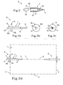
- a third embodiment of the solid roll 1 according to the invention is similar to the first embodiment of the solid roll 1 except concerning the second attachment means 8 of the adapter 6.
- the second attachment means 8 is a recess 14, which extends from an end 22 of the adapter 6 being adapted to face a dispenser and in the direction of the first attachment means 7.
- the recess 14 extends into the first attachment means 7.
- the recess 14 is adapted to be arranged to receive a shaft 15 rotatably mounted to a dispenser.
- the adapter 6 of the solid roll 1 in the third embodiment is shown in fig. 2 in a cross-sectional side view together with the shaft 15.
- the solid roll 1 is provided with one adapter 6 having the configuration shown in fig. 2
- the solid roll 1 is provided with two adapters 6 having the configuration shown in fig. 2 .
- a fifth embodiment of the solid roll 1 according to the invention is similar to the first embodiment of the solid roll 1 except concerning that the adapter 6 further comprises restriction means 16 for restricting the insertion of the adapter 6 into the solid roll 1.
- the adapter 6 in the fifth embodiment is shown in a side view in fig. 3a , a first end view in fig. 3b and a second end view in fig. 3c .
- the restriction means 16 is arranged to restrict the insertion of the adapter 6 into the solid roll 1 above all in order to enable a reliable attachment of the adapter 6 to a dispenser by the second attachment means 8.
- the restriction means 16 prevents the adapter 6 from being inserted into the solid roll 1 to such an extent that the second attachment means 8 is located at a position in which attachment to a dispenser can not be achieved or can not be achieved in a reliable way. Therefore, the restriction means 16 has a size and a shape, which prevent the restriction means 16 from being inserted into the solid roll 1 and the adapter 6 is thus permitted to be inserted into the solid roll 1 until the restriction means 16 is located adjacent one side 2, 3 of the solid roll 1.
- a plate having a form that is circular, oval, triangular or rectangular may constitute the restriction means 16.
- the restriction means 16 comprises a first side 16a, which is adapted to be arranged facing one side 2, 3 of the solid roll 1 and to be adjacent that side 2, 3 of the solid roll 1, and an opposite second side 16b, which is adapted to be arranged facing away from the side 2, 3, which the first side 16a is arranged to face.
- the second side 16b is adapted to be arranged facing a dispenser when the solid roll 1 is installed and held in the dispenser.
- the first attachment means 7 for attachment to the solid roll 1 is arranged extending from the first side 16a of the restriction means 16 and the second attachment means 8 for attachment to a dispenser is arranged extending from the second side 16b of the restriction means 16.
- the first attachment means 7 is essentially centred on the first side 16a of the restriction means 16 and extends essentially from the centre of the first side 16a of the restriction means 16.
- the second attachment means 8 is essentially aligned with the first attachment means 7.
- the second attachment means 8 is, in accordance with the first attachment means 7, preferably centred on the restriction means 16 and extends preferably essentially from the centre of the second side 16b of the restriction means 16. Furthermore, the first and second attachment means are, respectively, fixedly attached to the restriction means 16.
- the solid roll 1 is provided with one adapter 6 having the configuration shown in fig. 3a-c
- the solid roll 1 is provided with two adapters 6 having the configuration shown in fig. 3a-c
- a simplified cross-sectional view of the sixth embodiment of the solid roll 1 is shown in fig. 3d , in which view the outline of the solid roll 1 is shown with dashed lines.
- a dispenser 17 according to the invention is arranged to hold the solid roll 1 according to the invention by having complementary means 18 that are complementary to the second attachment means 8.
- the dispenser 17 according to the invention can either be arranged to hold a solid roll 1 being provided with only one adapter 6 on one side 2, 3 or to hold a solid roll 1 being provided with one adapter 6 on each side 2, 3.
- the adapter 6 according to the invention is arranged to adapt the solid roll 1 to be dispensed in various types of conventional dispensers having different configurations.
- a detailed explanation of the frame and other components of dispensers in which the solid 1 according to the present invention may be dispensed is not necessary for the purpose of the present disclosure.
- FIG. 4 shows a schematic cross-sectional view of a dispenser 17 according to the invention holding the solid roll 1 of the sixth embodiment according to the invention.
- the solid roll 1 in fig. 4 is provided with one adapter 6 on each side 2, 3.
- the dispenser 17 is provided with complementary means 18 that are complementary to the second attachment means 8 of the adapter 6.
- the complementary means 18 is, for example, a bearing 19 provided on each side of the dispenser 17 adapted to face the solid roll 1 held in the dispenser 17.
- the shaft 13 is then rotatably mounted in the bearing 19.
- the bearing 19 is preferably a roller bearing, but different kinds of bearings can be used, such as ball bearings, needle bearings and plain bearings of the self-lubricating type for example produced of nylon. Preferred are the types of bearings that will give a certain stability to the first and second attachment means 7, 8, such as roller, needle and plain bearings.
- a dispenser 17 according to the invention being adapted to hold one solid roll 1 with only one adapter 6 provided on one side 2, 3, the bearing 19 will have to withstand the momentum from the solid roll 1 on the first attachment means 7 and second attachment means 8.
- a dispenser 17 according to the invention being adapted to hold one solid roll 1 with one adapter 6 provided on each side 2, 3 of the solid roll 1 and thus being provided with two bearings 19, the bearings 19 will have to withstand momentum from the solid roll 1 on the first attachment means 7 and the second attachment means 8 during the installation of the solid roll 1 when the solid roll 1 might for a while only be mounted to one of the bearings 19.
- a dispenser 17 according to the invention arranged to hold the solid roll 1 according to the invention provided with one or two adapters 6 having a recess 14 as second attachment means 8 comprises one or two shafts 15 as the complementary means 18.
- a seventh embodiment of the solid roll 1 is similar to the fifth embodiment except for concerning the second attachment means 8 of the adapter 6.
- the second attachment means 8 in the seventh embodiment is similar to the second attachment means 8 in the third embodiment, i.e. it is a recess 14.
- the recess 14 extends from the end 22 of the adapter 6 being adapted to face a dispenser through the restriction means 16 and into the first attachment means 7.
- the adapter 6 in the seventh embodiment is shown in a cross-sectional side view in fig. 5a , a first end view in fig. 5b and a second end view in fig. 5c .
- the solid roll 1 is provided with one adapter 6 having the configuration shown in fig. 5a-c
- the solid roll 1 is provided with two adapters 6 having the configuration shown in fig. 5a-c .
- a ninth embodiment of the solid roll 1 is similar to the fifth embodiment except for concerning the first attachment means 7 of the adapter 6.
- the first attachment means 7 comprises three elongated attachment members 9, which are extending essentially parallel to each other.
- the three elongated attachment members 9 are arranged circumferentially and are adapted to be arranged extending near the centre line 5 of the solid roll 1 to encircle the centre line 5 of the solid roll 1.
- the adapter 6 in the ninth embodiment is shown in a side view in fig. 6a , a first end view in fig. 6b and a second end view in fig. 6c .
- the ninth embodiment of the solid roll 1 is shown in a cross-sectional view in fig.
- the solid roll 1 is provided with one adapter 6 having the configuration shown in fig. 6a-c .
- the solid roll 1 is provided with two adapters 6 having the configuration shown in fig. 6a-c .
- an eleventh embodiment and a twelfth embodiment of the solid roll 1 are respectively similar to the first embodiment and the second embodiment of the solid roll 1 except for concerning the first attachment means 7 of the adapter 6.
- the first attachment means 7 is similar to the first attachment means 7 in the ninth and tenth embodiment, respectively.
- the adapter 6 may comprise more than three elongated attachment members 9 arranged circumferentially and adapted to be arranged near the centre line 5 of the solid roll 1 to encircle the centre line 5 of the solid roll 1.
- One example of such an adapter 6, which has six elongated attachment members 9, is shown in a side view in fig. 7a , a first end view in fig. 7b and a second end view in fig. 7c .
- the first attachment means 7 further comprises a central body 20, whereby the elongated attachment members 9 protrude from the central body 20.
- the second attachment means may be a recess 14, which extends into the central body 20 of the first attachment means 7.
- the first attachment means 7 comprises one centred elongated attachment member 9 and at least two elongated attachment members 9 extending parallel to the centred elongated attachment member 9 and at a distance from the centred elongated attachment member 9.
- the elongated attachment members 9 extending parallel with the centred elongated attachment member 9 may be arranged, for example, in a row together with the centred elongated attachment member 9, in a circle around the centred elongated attachment member 9, at corners of a triangle, at corners of a square etc.
- the elongated attachment members 9 may have different lengths, whereby, for example, the centred elongated attachment member 9 may be longer than the other elongated attachment members 9.
- first attachment means 7 comprises one centred elongated attachment member 9 and two elongated attachment members 9 extending parallel to the centred elongated attachment member 9 and arranged in a row together with the centred elongated attachment member 9, in which restriction means 16 is comprised and in which the second attachment means 8 is a recess 14 extending into the restriction means 16 is shown in a side view in fig. 8 .
- the second attachment means 8 further comprises, except for the shaft 13, an attachment member 21 attached at an end 28 of the shaft 13 being adapted to be arranged adjacent or in a dispenser.
- the attachment member 21 is adapted to be arranged running parallel to the side 2, 3 of the solid roll 1 and may be adapted to be arranged at a distance from the side 2, 3 of the solid roll 1 or near or adjacent the side 2, 3.
- the attachment member 21 is a plate-like member, which, for example, is circular.
- the solid roll 1 may, for example, be inserted into a dispenser having an inner wall and an outer wall on each dispenser side to which the solid roll 1 is to be attached and a notch in the inner wall.
- the shaft 13 is then inserted into the notch in the inner wall and the attachment member 21 is positioned between the inner wall and the outer wall.
- the adapter 6 in such a still further embodiment also comprises a restriction means 16, the restriction means 16 and the attachment member 21 run parallel to each other.
- the second attachment means 8 comprises a shaft 13 and an attachment member 21 being a circular plate and in which the first attachment means 7 comprises one centred elongated attachment member 9 and two elongated attachment members 9 extending parallel to the centred elongated attachment member 9 and at a distance from the centred elongated attachment member 9 is shown in a side view in fig. 9a , a first end view in fig. 9b and a second end view in fig. 9c .
- embodiments of the solid roll 1 are similar to any of the first through eighth embodiments, i.e. similar to embodiments in which the adapter 6 comprises one elongated attachment member 9, except for concerning that the elongated attachment member 9 further comprises a helical winding 23 on its outer surface.
- the helical winding 23 may be wound in a right or left direction and may have any suitable pitch. If an adapter 6 comprises a helical winding 23, it is inserted into the solid roll 1 by a screwing process.
- a solid roll 1 comprises two adapters 6 having one elongated attachment member 9 comprising a helical winding 23, the direction of the helical winding 23 of the two adapters 6, respectively, may be the same or different.
- a solid roll 1 may comprise one adapter 6 with a helical winding 23 in a left direction and one adapter 6 with a helical winding 23 in a right direction.
- the adapter 6 has such a helical winding 23 that it may be screwed into the solid roll 1 against the direction of the winding of the flexible web-shaped material of the solid roll 1.
- the adapter 6 is a screw 24.
- the second attachment means 8 comprises the head 25 of the screw 24 and the first attachment means 7 comprises the part of the screw with a helical winding 23.
- the screw 24 may be any type of standard screw, but is preferably a specially designed screw having, for example, a specially designed head 25 such that mounting to a dispenser is enabled and facilitated.
- the screw 24 may comprise engagement means 26 for advancement into the solid roll 1.
- the engagement means 26 for advancement into the solid roll 1 may, for example, be a star-shaped or cross-shaped recess in the head of the screw.
- the helical winding 23 may be wound in a right or left direction and may have any suitable pitch.
- the second attachment means 8 of the screw 24 further comprises a recess 14 that extends through the engagement means 26 and at least partially into the head 25 of the screw 24 in the direction of the first attachment means 7.
- the recess 14 may also extend into the first attachment means 7.
- An example of an adapter 6, which is a screw 24 and which is provided with a recess 14, is shown in a side view in fig. 10a , in a first end view in fig. 10b and in a second end view in fig. 10c .
- the second attachment means 8 of the screw 24 further comprises a shaft attached to the screw head 25 and adapted to be mounted to a dispenser.
- the solid roll 1 may be a compact type of solid roll having a density of about 250-380 kg/m 3 or a more loosely wound type of solid roll having a density of about 140-250 kg/m 3 . If the adapter 6 comprises one elongated attachment member 9, the length of the elongated attachment member 9 is preferably about 5-20 mm if the solid roll 1 is a compact type of solid roll and about 5-50 mm if the solid roll 1 is a more loosely wound type of solid roll.
- the length of the elongated attachment members 9 may be about 2-5 mm if the solid roll 1 is a compact type of solid roll and about 5-8 mm if the solid roll 1 is a more loosely wound type of solid roll.
- the adapter 6 of the solid roll 1 according to the invention comprises more than one elongated attachment member 9, they may have different lengths.
- the solid roll 1 may also be provided with two adapters 6 having different configurations. Then any combinations of the above mentioned adapters 6 are possible.
- the solid roll 1 may be provided with two adapters 6 that comprises different numbers of elongated attachment members 9, with one adapter 6 comprising the restriction means 16 and one adapter 6 without the restriction means 16 or with one adapter 6 in which the elongated attachment member 9 comprises a helical winding 23 and one adapter 6 in which the elongated attachment member 9 does not comprise a helical winding 23.
- a solid roll 1 according to the invention When a solid roll 1 according to the invention is provided with one adapter 6 on each side 2, 3, the two adapters 6 have usually the same type of second attachment means 8. For example, the two adapters 6 have both recesses 14 as second attachment means 8 or the two adapters 6 have both shafts 13 as second attachment means 8. However, a solid roll 1 according to the invention may also be provided with one adapter 6 having a recess 14 as second attachment means 8 and one adapter 6 having a shaft 13 as second attachment means 8. Then the stacking of the solid rolls 1 for transport or storage in a packaging box is facilitated, since the shaft 13 of one solid roll 1 may be fitted into the recess 14 of another solid roll 1.
- the solid roll 1 is provided with one adapter 6 on each side 2, 3, which adapters 6 have elongated attachment members 9 overlapping each other in at least the centre area of the solid roll 1.
- the solid roll 1 may, which is shown in a cross-sectional view in fig.
- first adapter 6 wherein the first attachment means 7 comprises one elongated attachment member 9 and a second adapter 6 wherein the first attachment means 7 comprises at least three elongated attachment members 9, whereby the first adapter 6 and the second adapter 6 are adapted to be arranged such that the elongated attachment members 9 of the second adapter 6 encircle the elongated attachment member 9 of the first adapter 6 in at least a centre area of the solid roll 1.
- a combination of a first adapter 6 and a second adapter 6 may of course also comprise adapters 6 having other numbers of elongated attachment members than those numbers mentioned.
- the first adapter 6 may comprise three elongated attachment members 9 and the second adapter 6 may comprise six elongated attachment members 9.
- the second attachment means 8 of the adapters 6 in such a combination may be similar or different.
- the solid roll 1 may, for example, be a jumbo roll.
- the jumbo roll may, for example, weigh at least 500 g, preferably at least 800 g and most preferably at least 1000 g.
- the present invention also relates to an adapter 6 for a solid roll, which adapter 6 is the adapter that has been described above in the kit of the solid roll 1 and at least one adapter 6.
- first attachment means may comprise other numbers of elongated attachment members than those mentioned.
- the first attachment means may also comprise further structures than only elongated attachment members.
- shape of the second attachment means may also be varied in order to allow for attachment to various types of dispensers.
- complementary means of the dispenser may also be varied in order to be suited for the second attachment means.
Abstract
Description
- The present invention relates to a solid roll of flexible web-shaped material, such as paper or non-woven material, provided with at least one adapter, which solid roll is suited for installation and holding in various types of conventional dispensers and is ready to be loaded in a dispenser at delivery to the end consumer without the need of adding and fitting any extra adaptation parts. Furthermore, the invention relates to an adapter for a solid roll, an adapter combination for a solid roll and a dispenser for holding a solid roll according to the invention.
- Commercial and consumer products of flexible web-shaped material, such as toilet paper, hand towel paper, kitchen towel paper, industrial wiping paper and nonwoven wiping material, are typically distributed and dispensed in roll form. Small rolls with a diameter of 100 to 150 mm are normally used in households, whereas larger rolls, which often are called jumbo rolls and which can have a diameter of 200 to 400 mm, are utilized in commercial uses, i.e. in offices and in public washrooms etc. The jumbo rolls carry much more flexible web-shaped material than the small household rolls and are correspondingly much heavier. The small household rolls weigh 0,1 - 0,2 kg and the jumbo rolls weigh from 0,2 to 8,0 kg or even 10 kg and can carry 1500 m of flexible web-shaped material.
- Today there are different types of rolls, such as cored rolls, coreless rolls and solid rolls, on the market. These types of rolls have different characteristics, which will be further described below. Traditionally, the cored roll has been predominant on the market, whereas new market trends have introduced the coreless roll as well as the solid roll.
- The cored roll, which traditionally has been utilized, is typically produced on a hollow cylindrical core, around which the flexible web-shaped material is rolled up. For example, the hollow cylindrical core may be made of some type of cardboard or plastic material. After finished production, the hollow cylindrical core remains in the cored roll. Thus, the cored roll intended for the end consumer comprises the hollow cylindrical core defining a hollow space at the centre of the roll.
- The coreless roll, which has been introduced by new market trends, does not comprise any hollow cylindrical core around which the flexible web-shaped material is wound. However, the coreless roll comprises an opening extending through the centre of the roll. The coreless roll is produced on some type of mandrel belonging to the production equipment. The flexible web-shaped material is rolled up around the mandrel to form the roll and the mandrel is subsequently extracted and recycled after finished up-rolling. During extraction of the mandrel from the roll, an opening is created through the roll. The opening may collapse and assume a deformed shape, such as oval, flattened or star-shaped, during or after withdrawal of the mandrel, but the coreless roll intended for the end consumer still comprises an opening at the centre of the roll. The innermost windings of web-shaped material are normally attached to each other by addition of some water in order to act like a core. However, the central opening of the coreless roll is much smaller in diameter than the diameter of the core of the cored roll. One consequence thereof is, for example, that the coreless roll may comprise more flexible web-shaped material than the cored roll for a given outer diameter. A machine and method for the production of coreless rolls are, for example, described in
EP 1268330 . - The solid roll, which has been introduced recently on the market, does not comprise any hollow cylindrical core and neither any opening extending through the centre of the roll. The solid roll is not produced on any core, mandrel or the like, but even the innermost part of the roll is filled with flexible web-shaped material during production of the roll. The finished solid roll takes on the appearance of a compact cylinder completely filled with flexible web-shaped material and is essentially homogenous in a cross-section viewed from the side. The density range of the solid roll is 140 -380 kg/m3. However, there may be some deviation from the homogenous characteristic due to, for example, technical reasons during manufacturing or due to that a deviation is desired in the centre area. The density range of a centre part having a diameter of 10 mm may, for example, be between 20 kg/m3 less than the other parts of the roll and 20 kg/m3 more than the other parts of the roll. The density of the centre part having a diameter of 10 mm may be measured by unwinding a solid roll such that the remaining part of the solid roll has a diameter of 10 mm and thereafter measuring the volume and weight of the remaining part of the solid roll. Since the solid roll does not have any core or opening at the centre of the roll, the solid roll may comprise more meters of flexible web-shaped material for a given outer diameter compared to the cored and coreless rolls. A machine and method for the production of solid rolls are, for example, described in
EP 0580561 . - The core of cored rolls has to be taken away and discarded when all flexible web-shaped material has been used. The coreless and solid rolls are more environment friendly than the cored roll since all flexible web-shaped material of the coreless or solid rolls may be used and since they have no core that has to be discarded. In addition, cored rolls are more expensive to manufacture than coreless and solid rolls because of the expense of producing the cores and joining the product to the core.
- However, since cored rolls traditionally have been utilized, conventional dispensers used by consumers today are generally suited for cored rolls only. Many conventional dispensers comprise, for example, a spindle or the like on which the roll is to be mounted in a manner similar to ubiquitous bathroom toilet roll dispensers. Such a spindle is arranged to pass through or otherwise penetrate the inner space of the core of the cored roll such that the cored roll may rotate around the spindle. For example, the spindle may be a member of the dispenser being affixed to the dispenser at one end or may be a releasable member of the dispenser being adapted to be inserted into slots, pathways or the like defined in the sides of the dispenser.
- Since solid rolls have no opening extending through the roll, a solid roll is not suited for loading in dispensers for cored rolls comprising a spindle or the like to be inserted through the roll. Furthermore, since the central opening in coreless rolls might have assumed a deformed shape, since the diameter of the central opening is less than the diameter of the core of cored rolls and since the diameter of the central opening can vary with air moisture content, it may be difficult to fit a coreless roll into such dispensers. Furthermore, there is a risk that a coreless roll wobbles in such dispensers as material is drawn from the roll.
- One way to enable installation and holding in a dispenser of a coreless roll or a solid roll, respectively, is to utilize a dispenser that is specifically configured during its manufacture for loading coreless and/or solid rolls.
- One example of a type of dispenser that is specifically configured for holding coreless or solid rolls, respectively, is a disperser having the shape of a trough in which the roll is put. The flexible web-shaped material is fed over the upper edge of the trough or through a slit in the lower part. However, when there is only a few windings left of the solid roll, it might be difficult to get hold of the end of the flexible web-shaped material in such a dispenser and the user may have to pick up the solid roll to find the end of the flexible web-shaped material.
- Another example of a type of dispenser that is specifically configured for holding solid rolls is a dispenser that comprises a projection part on at least one dispenser side. Such a dispenser is, for example, disclosed in
WO 2004056250 . The projection part may be a pin or the like. When a new solid roll is loaded in such a dispenser, the projection part is forced to penetrate between windings of the solid roll. However, in order to be able to use as much as possible of the material of the solid roll, the projection part must be forced to penetrate at or near the innermost winding. Thus, the user has to try to fit the solid roll to the projection part such that it penetrates at or near the innermost winding. Furthermore, it is required that some force is applied for the penetration. - Another way to enable installation and holding in a dispenser of a coreless roll or a solid roll, respectively, is to adapt an existing dispenser for cored rolls for loading coreless or solid rolls, respectively, and/or to adapt coreless or solid rolls, respectively, to fit to such a dispenser.
- One way, which is well-known in the art, of adapting a coreless or solid roll for installation and holding in a dispenser for cored rolls comprises creation of a depression in each vertical side of a coreless roll or a solid roll, respectively, at the time of production and provision of an adapter that fits both into the depression and to a mounting structure of the dispenser. A method of producing a depression in a vertical side of a roll is, for example, disclosed in
US 5,620,148 . -
WO 99/60909 -
US 6,082,664 discloses an adapter for small solid or coreless rolls of paper material, in which rolls there are recesses or divots defined in the vertical sides of the rolls. The adapter is to be placed in a dispenser for cored rolls, in which dispenser there are slots defined in the sides of the dispenser. The recesses, which should be formed at the time of production, define a rotating axis for the coreless or solid roll and a protrusion extending from the adapter is arranged to be pressed into one of the recesses. An engaging member may extend substantially transverse from the adapter and may be insertable into and slidable along the slots in the sides of the dispenser. A pair of adapters may engage and hold the roll therebetween within the dispenser. -
US 6,592,068 discloses an adapter for small solid or coreless rolls of paper material, in which rolls there are recesses or divots defined in the vertical sides of the rolls. The adapter is to be placed in a dispenser for cored rolls, in which dispenser there are slots defined in the sides of the dispenser. The adapter includes a carriage having opposite side members attached to a transverse support arm. A protrusion is formed on one side of each side member, which protrusion is intended to at least partially engage into the recess in a vertical side of the solid or coreless roll. A pin is disposed on the other side of each side member and is intended to engage in one of the slots in the sides of the dispenser. - However, in order to enable installation and holding of coreless or solid rolls, respectively, in a dispenser for cored rolls by use of the adapters according to
WO 99/60909 US 6,082,664 andUS 6,592,068 , respectively, the rolls must be provided with a depression in each of their vertical sides. In use, the user has to fit those adapters, respectively, into both the depressions in the sides of the rolls and to the dispensers and ensure that reliable fitting is achieved to both the roll and the dispenser. Thus, some workload is then put on the user. Furthermore, the adapters according toUS 6,082,664 andUS 6,592,068 , respectively, are only possible to use in dispensers having slots or the like defined in their side walls. - Another way, which is known in the art, of adapting a coreless roll having a central aperture for loading in a dispenser for cored rolls comprises utilization of an adapter that is intended to be inserted into the aperture and to be attached to such a dispenser.
-
US 5,495,997 discloses a support spindle apparatus, which is intended to be inserted into the central aperture of a coreless toilet tissue roll to support the coreless roll in a toilet tissue dispenser cabinet of the type having opposed, elongated, generally vertically oriented guide slots. The support spindle apparatus comprises an elongated spindle body having a generally cruciform cross-section over most of its length. In use, the spindle apparatus is inserted into the aperture of a coreless roll such that one end is positioned outside the roll on one side of the roll and the other end is positioned outside the roll on the opposite side of the roll. Thereafter, one end of the spindle apparatus may be inserted into a slot at one side of a dispenser and the other end of the spindle apparatus may be inserted into a slot in the opposite side of the dispenser. The support spindle apparatus further comprises a roll stop element fixedly attached to the elongated spindle body to prevent movement of the roll relative to the spindle apparatus in a single direction. -
US 5,868,342 describes a roll spindle intended to be used in modification of a multi-roll dispenser normally used to dispense tissue from rolls of toilet tissue having centre cores to dispense tissue from coreless rolls. One spindle is inserted into each roll in the multi-roll dispenser. The spindle comprises a spindle shaft and a plurality of roll engagement elements rotatably journaled on the spindle shaft. Furthermore, the spindle has a tapered distal end and the spindle is inserted into a roll with the tapered end first. At the other end of the spindle, a mounting member is provided for affixing the spindle to the dispenser. During use, the coreless roll may be rotated around the spindle shaft by means of the rotatably journaled roll engagement members, whereas the spindle shaft is fixed in position, i.e. not rotated. - However, in order to enable installation and holding of coreless rolls in a dispenser for cored rolls by use of the spindles according to
US 5,495,997 andUS 5,868,342 , respectively, the user has to fit those spindles, respectively, to the aperture of a coreless roll. Since the aperture in a coreless roll may have collapsed and assumed a deformed shape, as mentioned above, it might be tricky and time-consuming to fit such a spindle to the aperture and to avoid that windings of web-material are penetrated during insertion of such a spindle. Furthermore, the spindles according toUS 5,495,997 andUS 5,868,342 , respectively, are only suited for rolls having a central aperture, such as coreless rolls, whereby they are not suited for solid rolls. Furthermore, the spindle apparatus according toUS 5,868,342 may only be used in a special type of dispenser. - Therefore, there is still a need for a simple and reliable way of achieving the possibility to install and hold solid rolls of flexible web-shaped material in a dispenser such that flexible web-shaped material may be dispensed in a reliable and user-friendly way. Furthermore, there is a need for the possibility to achieve solid rolls of flexible web-shaped material that are adapted for enabling installation and holding in various types of dispensers that hold a roll in its central line. There is also a need for the possibility to achieve solid rolls that are adapted such that they are ready to be used in a dispenser at delivery, i e without the user having to add any adaptation parts.
- Accordingly, it is an object of the present invention to provide an improved and simplified way of enabling use of solid rolls.
- This object is achieved through a solid roll wound of flexible web-shaped material, such as paper or non-woven material, which solid roll has two opposite sides, an envelope surface between the two sides and a centre line, the innermost winding being essentially located at least near the centre line, and which solid roll is provided with at least one adapter comprising:
- first attachment means for attachment to the solid roll, the first attachment means being adapted to be arranged extending into the solid roll from one of the sides, and
- second attachment means for attachment to a dispenser, the second attachment means being adapted to be arranged enabling attachment to the dispenser, wherein the first attachment means comprises at least one elongated attachment member being adapted to be arranged extending in or near the centre line of the solid roll and to fixate the adapter to the flexible web-shaped material of the solid roll through frictional engagement and wherein the at least one elongated attachment member comprises a portion with a tapered shape ending in a pointed distal end, said pointed distal end being arranged to be positioned within said solid roll.
- In one aspect of the present invention, the solid roll is provided with one adapter on each of the two sides.
- In a further aspect of the present invention, the solid roll is provided with two adapters, whereby the first attachment means of the two adapters, respectively, comprises different numbers of elongated attachment members.
- According to another aspect of the present invention, the solid roll is provided with a first adapter on one side and a second adapter on the opposite side, whereby the first attachment means of the first adapter comprises one elongated attachment member adapted to be arranged in or near the centre line of the solid roll and whereby the first attachment means of the second adapter comprises at least three elongated attachment members extending parallel to each other, which at least three elongated attachment members are arranged circumferentially and are adapted to be arranged near the centre line of the solid roll to encircle the centre line of the solid roll, and whereby the first adapter and the second adapter are adapted to be arranged such that the elongated attachment members of the second adapter encircle the elongated attachment member of the first adapter in at least a centre area of the solid roll.
- According to yet another aspect of the present invention, the solid roll is provided with a first adapter on one side and a second adapter on the opposite side, whereby the second attachment means of the first adapter is a recess extending into the first attachment means, which recess is adapted to be arranged to receive a shaft affixed to a dispenser or rotatably mounted to a dispenser, and whereby the second attachment means of the second adapter is a shaft, which is adapted to be arranged extending away from the solid roll and to be rotatably mounted to a dispenser.
- According to another aspect of the present invention, the solid roll is a jumbo roll, weighing at least 500 g and preferably at least 800 g.
- According to still a further aspect of the present invention, the solid roll is a jumbo roll, weighing at least 1000 g.
- Another object of the present invention is to provide an adapter for a solid roll for simplifying and improving the installation and holding of a solid roll in a dispenser.
- This object is achieved through an adapter for a solid roll wound of flexible web-shaped material, such as paper or non-woven material, which solid roll has two opposite sides, an envelope surface between the two sides and a centre line the innermost winding being essentially located at least near the centre line, the adapter comprising:
- first attachment means for attachment to the solid roll, the first attachment means being adapted to be arranged extending into the solid roll from one of the sides, and
- second attachment means for attachment to a dispenser, the second attachment means being adapted to be arranged enabling attachment to the dispenser, wherein the first attachment means comprises at least one elongated attachment being adapted to be arranged extending in or near the centre line of the solid roll and to fixate the adapter to the flexible web-shaped material of the solid roll through frictional engagement and
- wherein the at least one elongated attachment member comprises a portion with a tapered shape ending in a pointed distal end, said pointed distal end being arranged to be positioned within said solid roll.
- According to one aspect of the present invention, the adapter is used for jumbo rolls, weighing at least 500 g and preferably at least 800 g.
- According to a further aspect of the present invention, the adapter is used for jumbo rolls, weighing at least 1000 g.
- In further embodiments of the solid roll and the adapter according to the present invention, the adapter further comprises restriction means for restricting insertion of the adapter into the solid roll, the restriction means comprising a first side being adapted to be arranged facing and adjacent to one side of the solid roll and an opposite second side adapted to be arranged facing away from the one side of the solid roll, whereby the first attachment means for attachment to the solid roll is arranged extending from the first side of the restriction means and whereby the second attachment means for attachment to a dispenser is arranged extending from the second side of the restriction means.
- In other embodiments of the solid roll and the adapter according to the present invention, the first attachment means comprises one elongated attachment member adapted to be arranged extending in or near the centre line of the solid roll, whereby the elongated attachment member comprises a helical winding.
- In further embodiments of the solid roll and the adapter according to the present invention, the first attachment means comprises at least three elongated attachment members extending parallel to each other, which at least three elongated attachment members are arranged circumferentially and are adapted to be arranged extending near the centre line of the solid roll to encircle the centre line of the solid roll.
- In other embodiments of the solid roll and the adapter according to the present invention, the first attachment means comprises one centred elongated attachment member and at least two elongated attachment members extending parallel to the centred elongated attachment member and at a distance from the centred elongated attachment member.
- Preferably, the second attachment means is adapted to be arranged extending in the direction of the centre line of the solid roll.
- In further embodiments of the solid roll and the adapter according to the present invention, the second attachment means comprises a shaft, which is adapted to be arranged extending away from the solid roll and to be rotatably mounted to a dispenser.
- In still further embodiments of the solid roll and the adapter according to the present invention, the adapter further comprises restriction means for restricting insertion of the adapter into the solid roll, the restriction means comprising a first side being adapted to be arranged facing and adjacent to one side of the solid roll and an opposite second side adapted to be arranged facing away from the one side of the solid roll, whereby the second attachment means is a recess extending into the restriction means, which recess is adapted to be arranged to receive a shaft affixed to a dispenser or rotatably mounted to a dispenser.
- In other embodiments of the present invention, the second attachment means is a recess extending from an end of the adapter being arranged to face a dispenser and in the direction of the first attachment means, which recess is adapted to be arranged to receive a shaft affixed to a dispenser or rotatably mounted to a dispenser.
- In further embodiments of the solid roll and the adapter according to the present invention, the second attachment means comprises a shaft, which is adapted to be arranged extending away from the solid roll and to be rotatably mounted to a dispenser, and an attachment member attached to an end of the shaft adapted to be arranged adjacent or in a dispenser, which attachment member is adapted to be arranged running parallel to said one side of the solid roll.
- In still further embodiments of the solid roll and the adapter according to the present invention, the second attachment means comprises an attachment member adapted to be arranged running parallel to said one side of the solid roll, whereby said attachment member is a plate-like member.
- In other embodiments of the solid roll and the adapter according to the present invention, the adapter is a screw.
- The present invention further refers to a dispenser, which is arranged to hold a solid roll according to the invention by having complementary means being complementary to the second attachment means.
- The present invention also refers to an adapter combination comprising a first adapter and a second adapter according to the invention, whereby the first attachment means of the first adapter and the second adapter, respectively, comprises different numbers of elongated attachment members.
- The present invention further refers to an adapter combination comprising a first adapter according to the invention in which the first attachment means comprises one elongated attachment member adapted to be arranged extending in or near the centre line of the solid roll and a second adapter according to the invention in which the first attachment means comprises at least three elongated attachment members extending parallel to each other, which at least three elongated attachment members are arranged circumferentially and are adapted to be arranged extending near the centre line of the solid roll to encircle the centre line of the solid roll, wherein the first adapter and the second adapter are adapted to be arranged such that the elongated attachment members of the second adapter encircle the elongated attachment member of the first adapter in at least a centre area of the solid roll.
- The present invention also refers to an adapter combination comprising a first adapter in which the second attachment means is a shaft, which is adapted to be arranged extending away from the solid roll and to be rotatably mounted to a dispenser, and a second adapter in which the second attachment means is a recess extending into the first attachment means, which recess is adapted to be arranged to receive a shaft affixed to a dispenser or rotatably mounted to a dispenser.
- Still other objects and features of the present invention will become apparent from the following detailed description considered in conjunction with the accompanying drawings. It is to be understood, however, that the drawings are designed solely for purposes of illustration and not as a definition of the limits of the invention, for which reference should be made to the appended claims. It should be further understood that the drawings are not necessarily drawn to scale and that, unless otherwise indicated, they are merely intended to conceptually illustrate the structures and procedures described herein.
- In the drawings, wherein like reference characters denote similar elements throughout the several views:
-
Fig. 1a shows a cross-sectional view of the first embodiment of a solid roll according to the invention. -
Fig. 1b shows a cross-sectional view of the second embodiment of the solid roll according to the invention. -
Fig. 1c shows a first end view of an adapter in the first and second embodiments of the solid roll according to the invention. -
Fig. 1d shows a second end view of the adapter in the first and second embodiments of the solid roll according to the invention. -
Fig. 2 shows a cross-sectional side view of the adapter in the third and fourth embodiments of the solid roll according to the invention. -
Fig. 3a shows a side view of the adapter in the fifth and sixth embodiments of the solid roll according to the invention. -
Fig. 3b shows a first end view of the adapter according tofig. 3a . -
Fig. 3c shows a second end view of the adapter according tofig. 3a . -
Fig. 3d shows a cross-sectional view of the sixth embodiment of the solid roll according to the invention. -
Figure 4 shows a schematic cross-sectional view of a dispenser according to the invention holding the solid roll according to the sixth embodiment. -
Fig. 5a shows a cross-sectional side view of the adapter in the seventh and eighth embodiments of the solid roll according to the invention. -
Fig. 5b shows a first end view of the adapter according tofig. 5a . -
Fig. 5c shows a second end view of the adapter according tofig. 5a . -
Fig. 6a shows a side view of the adapter in the ninth and tenth embodiments of the solid roll according to the invention. -
Fig. 6b shows a first end view of the adapter according tofig. 6a . -
Fig. 6c shows a second end view of the adapter according tofig. 6a . -
Fig. 6d shows a cross-sectional view of the ninth embodiment of the solid roll according to the invention. -
Fig. 7a shows a side view of an alternative adapter. -
Fig. 7b shows a first end view of the adapter according tofig. 7a . -
Fig. 7c shows a second end view of the adapter according tofig. 7a . -
Fig. 8 shows a side view of another alternative adapter. -
Fig. 9a shows a side view of a further alternative adapter. -
Fig. 9b shows a first end view of the adapter according tofig. 9a . -
Fig. 9c shows a second end view of the adapter according tofig. 9a . -
Fig. 10a shows a side view of yet an alternative adapter. -
Fig. 10b shows a first end view of the adapter according tofig. 10a . -
Fig. 10c shows a second end view of the adapter according tofig. 10a . -
Fig. 11 shows a cross-sectional view of a solid roll being provided with a first adapter and a second adapter. -
Figures 1a and 1b show a simplified cross-sectional view of a first embodiment and a second embodiment, respectively, of asolid roll 1 of flexible web-shaped material according to the present invention, in which views the outline of thesolid rolls 1 is shown with dashed lines. As mentioned above, solid rolls of flexible web-shaped material do not comprise any hollow cylindrical core as cored rolls and neither any aperture extending through the centre of the roll as coreless rolls. Instead, the innermost part of solid rolls is filled with flexible web-shaped material. Thesolid roll 1 according to the invention may be of any types and sizes, including jumbo rolls. - The
solid roll 1, being cylinder-shaped, has twoopposite sides envelope surface 4 between the twosides solid roll 1 is wound properly and essentially evenly of flexible web-shaped material, the innermost winding is essentially located at the centre line 5. Usually, solid rolls are properly and essentially evenly wound of flexible web-shaped material and therefore the innermost winding is essentially located at the centre line 5 or at least near the centre line 5. - In accordance with the invention, the
solid roll 1 is provided with at least oneadapter 6, whichadapter 6 is adapted to be arranged on one of thesides solid roll 1 may be provided with oneadapter 6 only, i.e. oneadapter 6 on one of thesides adapters 6, i.e. with oneadapter 6 on each of the twosides fig. 1a , thesolid roll 1 is provided with oneadapter 6 only. In the second embodiment, which is shown infig. 1b , thesolid roll 1 is provided with twoadapters 6. Theadapter 6 in the first embodiment and theadapters 6 in the second embodiment all have the same configuration. A first and second end view of theadapter 6 in the first and second embodiments are, respectively, shown infig. 1c and fig. 1d . In other embodiments, thesolid roll 1 is, however, provided with twoadapters 6 having different configurations. This will be further described below. - The
adapter 6 is adapted to be partly inserted into thesolid roll 1 and comprises first attachment means 7 for attachment to thesolid roll 1 and second attachment means 8 for attachment to a dispenser. - The first attachment means 7 for attachment of the
adapter 6 to thesolid roll 1 is adapted to be arranged extending into the solid roll from oneside solid roll 1 and is adapted to engage thesolid roll 1 in or near its centre line 5. - The second attachment means 8 for attachment of the
adapter 6 to a dispenser is adapted to be arranged enabling attachment to a dispenser. Preferably, the second attachment means 8 is adapted to be arranged extending in the direction of the centre line 5 of thesolid roll 1. The second attachment means 8 is adapted to allow attachment of theadapter 6 to various types of conventional dispensers including conventional dispensers for cored rolls as well as dispensers intended for solid and coreless rolls being provided with depressions in their sides. In the first and second embodiments of thesolid roll 1, the second attachment means 8 comprises ashaft 13, which is adapted to be arranged extending away from thesolid roll 1 and to be rotatably mounted to complementary means in a dispenser. Examples of complementary means in a dispenser to which theshaft 13 may be mounted are different types of bearings. However, as will be further described below, the shape of the second attachment means 8 may be varied in further embodiments in order to fit to different complementary means in different types of conventional dispensers. In some cases it might also be possible to change the complementary means in a conventional dispenser in order to fit to the second attachment means 8. - Furthermore, the first attachment means 7 of the
adapter 6 in the first and second embodiments comprises oneelongated attachment member 9, which for example has the shape of a pin, tube or the like and which is adapted to be arranged extending in or near the centre line 5 of thesolid roll 1. Theelongated attachment member 9 is adapted to fixate theadapter 6 to the flexible web-shaped material of thesolid roll 1 through frictional engagement. Even if the first attachment means 7 of theadapter 6 in the first and second embodiments of thesolid roll 1 comprises oneelongated attachment member 9, theadapter 6 may in other embodiments of thesolid roll 1 comprise more than oneelongated attachment member 9. Other embodiments of the present invention, in which theadapter 6 comprises more than oneelongated attachment member 9 adapted to be arranged to extend in or near the centre line of thesolid roll 1 will be further described below. - The
elongated attachment member 9 is adapted to be inserted into thesolid roll 1 between windings of flexible web-shaped material since even the innermost part of thesolid roll 1 is filled with material. If thesolid roll 1 is essentially evenly wound with flexible web-shaped material, which it usually is, then the centre line 5 of thesolid roll 1 coincides at least essentially with the rotational axis of thesolid roll 1. However, after insertion of theelongated attachment member 9 into thesolid roll 1, the second attachment means 8 defines arotational centre line 10 for thesolid roll 1, around which thesolid roll 1 will rotate when held in a dispenser. - In order to be able to unwind and use all or essentially all flexible web-shaped material of the
solid roll 1, it is important that theelongated attachment member 9 is inserted in or near the innermost winding. Since solid rolls usually are properly and essentially evenly wound of flexible web-shaped material, and the innermost winding therefore is essentially located at the centre line 5 or at least near the centre line 5, it is important that theelongated attachment member 9 is inserted in or near the centre line 5 of thesolid roll 1. In the first and second embodiments, theelongated attachment member 9 is preferably inserted essentially along the centre line 5 of thesolid roll 1 and most preferably along the centre line 5 of thesolid roll 1. - Since even the innermost part of the
solid roll 1 is filled with material, theelongated attachment member 9 must be forced to penetrate into thesolid roll 1. In the first and second embodiments, theelongated attachment member 9 comprises aportion 12 with a tapered shape ending in a pointeddistal end 11 in order to facilitate the penetration of theelongated attachment member 9 into thesolid roll 1. Theportion 12 having a tapered shape may constitute only a part of theelongated attachment member 9 or the completeelongated attachment member 9. The tapering of theportion 12 having a tapered shape may be gradual or stepwise to the pointeddistal end 11. Theadapter 6 is inserted with the pointeddistal end 11 first, which may be sharply pointed. However, in other embodiments theelongated attachment member 9 does not comprise a taperedportion 12 nor a pointeddistal end 11. Furthermore, in still other embodiments comprising more than oneelongated attachment member 9, only one or some of theelongated attachment members 9 comprise a taperedportion 12 and a pointeddistal end 11. - The pointed
distal end 11 and the taperedportion 12 ease insertion of theelongated attachment member 9 and reduce the force required for insertion. Nevertheless, the insertion of theelongated attachment member 9 requires that a relatively high pressure is applied. Furthermore, at insertion of theelongated attachment member 9 of theadapter 6 into thesolid roll 1 it is important, as above described, that theelongated attachment member 9 is inserted near or in the centre line of thesolid roll 1 in order to be able to unwind and use essentially all flexible web-shaped material. If twoadapters 6 are to be inserted into thesolid roll 1, it is also important that theelongated attachment members 9 of the twoadapters 6, respectively, are essentially aligned such that therotational centre line 10 that the second attachment means 8 of the twoadapters 6, respectively, defines will be essentially the same line in thesolid roll 1. Therefore, the insertion of theadapter 6 is preferably performed at the time of manufacture of thesolid roll 1 or at least before thesolid roll 1 reaches the end consumer. By performing the insertion of theadapter 6 at a factory, the insertion may be performed under controlled circumstances. For example, a force that is high enough, but not too high, may then be applied for the insertion of theadapter 6 into thesolid roll 1, suitable means may be applied for the insertion and the insertion may be controlled to be performed such that theelongated attachment member 9 is inserted in or near the centre line of thesolid roll 1. Furthermore, by performing the insertion of theadapter 6 into thesolid roll 1 before thesolid roll 1 reaches the end consumer, a kit with thesolid roll 1 provided with one or twoadapters 6 may be delivered to the end consumer. This implies that thesolid roll 1 is ready for use at delivery, i.e. that the user does not have to apply any adapter(s) before loading in a dispenser. Thereby, the end consumer does not have to deal with the difficulties concerning insertion of the adapter(s) 6 into thesolid roll 1, concerning fitting of the adapter(s) 6 such that the adapter(s) 6 is/are inserted in or near the centre line of the solid roll and, if twoadapters 6 are to be used, concerning alignment of the twoadapters 6. - Preferably, the
elongated attachment member 9 has a circular cross-section, but the cross-section may also have other shapes, such as for example oval, triangular, rectangular or star-shaped. Theelongated attachment member 9 could also have a central body with a plurality of pins protruding from it. The length and the diameter of theelongated attachment member 9 must be suited for holding thesolid roll 1 securely and for delaying collapse when there are only a few windings left of material of thesolid roll 1. - Preferably, the
adapter 6 is produced of a metal, such as steel, aluminium alloys etc. However, other materials like for example plastic materials or pressed wood may also be used. Theadapter 6 is relatively easy to produce and may be produced at a relatively low material cost. Furthermore, theadapter 6 is preferably disposable, but may also be non-disposable. - The
adapter 6 in the first and the second embodiments of thesolid roll 1 has, as may be seen infigs. 1a-1d , the shape of a pin or the like, whereby one end part constitutes the first attachment means 7 and the other end part constitutes the second attachment means 8. In order to enable reliable attachment of theadapter 6 to thesolid roll 1, the end part constituting the first attachment means 7 must then be positioned within thesolid roll 1 such that reliable attachment of theadapter 6 to thesolid roll 1 is achieved. Furthermore, the end part constituting the second attachment means 8 must then be positioned outside thesolid roll 1 such that reliable attachment to a dispenser may be achieved. - A third embodiment of the
solid roll 1 according to the invention is similar to the first embodiment of thesolid roll 1 except concerning the second attachment means 8 of theadapter 6. In the third embodiment of thesolid roll 1, the second attachment means 8 is arecess 14, which extends from anend 22 of theadapter 6 being adapted to face a dispenser and in the direction of the first attachment means 7. In the third embodiment, therecess 14 extends into the first attachment means 7. However, in other embodiments the recess does not extend into the first attachment means 7. Therecess 14 is adapted to be arranged to receive ashaft 15 rotatably mounted to a dispenser. Theadapter 6 of thesolid roll 1 in the third embodiment is shown infig. 2 in a cross-sectional side view together with theshaft 15. In the third embodiment, thesolid roll 1 is provided with oneadapter 6 having the configuration shown infig. 2 , whereas in a fourth embodiment, thesolid roll 1 is provided with twoadapters 6 having the configuration shown infig. 2 . - A fifth embodiment of the
solid roll 1 according to the invention is similar to the first embodiment of thesolid roll 1 except concerning that theadapter 6 further comprises restriction means 16 for restricting the insertion of theadapter 6 into thesolid roll 1. Theadapter 6 in the fifth embodiment is shown in a side view infig. 3a , a first end view infig. 3b and a second end view infig. 3c . The restriction means 16 is arranged to restrict the insertion of theadapter 6 into thesolid roll 1 above all in order to enable a reliable attachment of theadapter 6 to a dispenser by the second attachment means 8. Thus, as will be described further below, the restriction means 16 prevents theadapter 6 from being inserted into thesolid roll 1 to such an extent that the second attachment means 8 is located at a position in which attachment to a dispenser can not be achieved or can not be achieved in a reliable way. Therefore, the restriction means 16 has a size and a shape, which prevent the restriction means 16 from being inserted into thesolid roll 1 and theadapter 6 is thus permitted to be inserted into thesolid roll 1 until the restriction means 16 is located adjacent oneside solid roll 1. For example, a plate having a form that is circular, oval, triangular or rectangular may constitute the restriction means 16. - The restriction means 16 comprises a
first side 16a, which is adapted to be arranged facing oneside solid roll 1 and to be adjacent thatside solid roll 1, and an oppositesecond side 16b, which is adapted to be arranged facing away from theside first side 16a is arranged to face. Thus, thesecond side 16b is adapted to be arranged facing a dispenser when thesolid roll 1 is installed and held in the dispenser. - In the
adapter 6 in the fifth embodiment of thesolid roll 1, the first attachment means 7 for attachment to thesolid roll 1 is arranged extending from thefirst side 16a of the restriction means 16 and the second attachment means 8 for attachment to a dispenser is arranged extending from thesecond side 16b of the restriction means 16. The first attachment means 7 is essentially centred on thefirst side 16a of the restriction means 16 and extends essentially from the centre of thefirst side 16a of the restriction means 16. In order to enable smooth rotation of thesolid roll 1 around therotational centre line 10, which as mentioned above is defined by the second attachment means 8, the second attachment means 8 is essentially aligned with the first attachment means 7. Therefore, the second attachment means 8 is, in accordance with the first attachment means 7, preferably centred on the restriction means 16 and extends preferably essentially from the centre of thesecond side 16b of the restriction means 16. Furthermore, the first and second attachment means are, respectively, fixedly attached to the restriction means 16. - In the fifth embodiment, the
solid roll 1 is provided with oneadapter 6 having the configuration shown infig. 3a-c , whereas in a sixth embodiment, thesolid roll 1 is provided with twoadapters 6 having the configuration shown infig. 3a-c . A simplified cross-sectional view of the sixth embodiment of thesolid roll 1 is shown infig. 3d , in which view the outline of thesolid roll 1 is shown with dashed lines. - A
dispenser 17 according to the invention is arranged to hold thesolid roll 1 according to the invention by havingcomplementary means 18 that are complementary to the second attachment means 8. Thus, thedispenser 17 according to the invention can either be arranged to hold asolid roll 1 being provided with only oneadapter 6 on oneside solid roll 1 being provided with oneadapter 6 on eachside adapter 6 according to the invention is arranged to adapt thesolid roll 1 to be dispensed in various types of conventional dispensers having different configurations. However, a detailed explanation of the frame and other components of dispensers in which the solid 1 according to the present invention may be dispensed, is not necessary for the purpose of the present disclosure. -
Figure 4 shows a schematic cross-sectional view of adispenser 17 according to the invention holding thesolid roll 1 of the sixth embodiment according to the invention. Thus, thesolid roll 1 infig. 4 is provided with oneadapter 6 on eachside dispenser 17 is provided withcomplementary means 18 that are complementary to the second attachment means 8 of theadapter 6. In order to suit for the second attachment means 8 of theadapter 6 in the sixth embodiment of thesolid roll 1, which is oneshaft 13, the complementary means 18 is, for example, abearing 19 provided on each side of thedispenser 17 adapted to face thesolid roll 1 held in thedispenser 17. Theshaft 13 is then rotatably mounted in thebearing 19. When thesolid roll 1 is installed in thedispenser 17 it is held securely in thedispenser 17 by theelongated attachment member 9 and theshaft 13 of each of the twoadapters 6 and is able to rotate freely in the twobearings 19. - The
bearing 19 is preferably a roller bearing, but different kinds of bearings can be used, such as ball bearings, needle bearings and plain bearings of the self-lubricating type for example produced of nylon. Preferred are the types of bearings that will give a certain stability to the first and second attachment means 7, 8, such as roller, needle and plain bearings. In adispenser 17 according to the invention being adapted to hold onesolid roll 1 with only oneadapter 6 provided on oneside solid roll 1 on the first attachment means 7 and second attachment means 8. Furthermore, in adispenser 17 according to the invention being adapted to hold onesolid roll 1 with oneadapter 6 provided on eachside solid roll 1 and thus being provided with twobearings 19, thebearings 19 will have to withstand momentum from thesolid roll 1 on the first attachment means 7 and the second attachment means 8 during the installation of thesolid roll 1 when thesolid roll 1 might for a while only be mounted to one of thebearings 19. - A
dispenser 17 according to the invention arranged to hold thesolid roll 1 according to the invention provided with one or twoadapters 6 having arecess 14 as second attachment means 8 comprises one or twoshafts 15 as thecomplementary means 18. - A seventh embodiment of the
solid roll 1 is similar to the fifth embodiment except for concerning the second attachment means 8 of theadapter 6. The second attachment means 8 in the seventh embodiment is similar to the second attachment means 8 in the third embodiment, i.e. it is arecess 14. In the seventh embodiment, therecess 14 extends from theend 22 of theadapter 6 being adapted to face a dispenser through the restriction means 16 and into the first attachment means 7. Theadapter 6 in the seventh embodiment is shown in a cross-sectional side view infig. 5a , a first end view infig. 5b and a second end view infig. 5c . In the seventh embodiment, thesolid roll 1 is provided with oneadapter 6 having the configuration shown infig. 5a-c , whereas in an eighth embodiment, thesolid roll 1 is provided with twoadapters 6 having the configuration shown infig. 5a-c . - A ninth embodiment of the
solid roll 1 is similar to the fifth embodiment except for concerning the first attachment means 7 of theadapter 6. In the ninth embodiment the first attachment means 7 comprises threeelongated attachment members 9, which are extending essentially parallel to each other. The threeelongated attachment members 9 are arranged circumferentially and are adapted to be arranged extending near the centre line 5 of thesolid roll 1 to encircle the centre line 5 of thesolid roll 1. Theadapter 6 in the ninth embodiment is shown in a side view infig. 6a , a first end view infig. 6b and a second end view infig. 6c . The ninth embodiment of thesolid roll 1 is shown in a cross-sectional view infig. 6d , whereby thesolid roll 1 is provided with oneadapter 6 having the configuration shown infig. 6a-c . In a tenth embodiment, thesolid roll 1 is provided with twoadapters 6 having the configuration shown infig. 6a-c . - An eleventh embodiment and a twelfth embodiment of the solid roll 1 (not shown) are respectively similar to the first embodiment and the second embodiment of the
solid roll 1 except for concerning the first attachment means 7 of theadapter 6. In the eleventh and twelfth embodiment, the first attachment means 7 is similar to the first attachment means 7 in the ninth and tenth embodiment, respectively. - In other embodiments of the
solid roll 1, theadapter 6 may comprise more than threeelongated attachment members 9 arranged circumferentially and adapted to be arranged near the centre line 5 of thesolid roll 1 to encircle the centre line 5 of thesolid roll 1.
One example of such anadapter 6, which has six elongatedattachment members 9, is shown in a side view infig. 7a , a first end view infig. 7b and a second end view infig. 7c . - In alternatives (not shown) of embodiments in which the
adapter 6 comprises more than oneelongated attachment member 9, the first attachment means 7 further comprises a central body 20, whereby theelongated attachment members 9 protrude from the central body 20. The second attachment means may be arecess 14, which extends into the central body 20 of the first attachment means 7. - Further alternatives of embodiments of the
solid roll 1 are similar to any of the above described embodiments except for concerning the first attachment means 7. In the further alternatives, the first attachment means 7 comprises one centredelongated attachment member 9 and at least twoelongated attachment members 9 extending parallel to the centredelongated attachment member 9 and at a distance from the centredelongated attachment member 9. Theelongated attachment members 9 extending parallel with the centredelongated attachment member 9 may be arranged, for example, in a row together with the centredelongated attachment member 9, in a circle around the centredelongated attachment member 9, at corners of a triangle, at corners of a square etc. However, other arrangements of theelongated members 9 are also possible. Furthermore, theelongated attachment members 9 may have different lengths, whereby, for example, the centredelongated attachment member 9 may be longer than the otherelongated attachment members 9. - One example of an embodiment in which the first attachment means 7 comprises one centred
elongated attachment member 9 and twoelongated attachment members 9 extending parallel to the centredelongated attachment member 9 and arranged in a row together with the centredelongated attachment member 9, in which restriction means 16 is comprised and in which the second attachment means 8 is arecess 14 extending into the restriction means 16 is shown in a side view infig. 8 . - Still further alternatives of embodiments of the
solid roll 1 are similar to any of the above described first, second, fifth or sixth embodiments except for concerning the second attachment means 8. In the still further embodiments, the second attachment means 8 further comprises, except for theshaft 13, anattachment member 21 attached at anend 28 of theshaft 13 being adapted to be arranged adjacent or in a dispenser. Theattachment member 21 is adapted to be arranged running parallel to theside solid roll 1 and may be adapted to be arranged at a distance from theside solid roll 1 or near or adjacent theside attachment member 21 is a plate-like member, which, for example, is circular. Thesolid roll 1 according to any of the still further embodiments may, for example, be inserted into a dispenser having an inner wall and an outer wall on each dispenser side to which thesolid roll 1 is to be attached and a notch in the inner wall. Theshaft 13 is then inserted into the notch in the inner wall and theattachment member 21 is positioned between the inner wall and the outer wall. If theadapter 6 in such a still further embodiment also comprises a restriction means 16, the restriction means 16 and theattachment member 21 run parallel to each other. - One example of an embodiment in which the second attachment means 8 comprises a
shaft 13 and anattachment member 21 being a circular plate and in which the first attachment means 7 comprises one centredelongated attachment member 9 and twoelongated attachment members 9 extending parallel to the centredelongated attachment member 9 and at a distance from the centredelongated attachment member 9 is shown in a side view infig. 9a , a first end view infig. 9b and a second end view infig. 9c . - Yet further alternatives of embodiments of the
solid roll 1 are similar to any of the first through eighth embodiments, i.e. similar to embodiments in which theadapter 6 comprises oneelongated attachment member 9, except for concerning that theelongated attachment member 9 further comprises a helical winding 23 on its outer surface. The helical winding 23 may be wound in a right or left direction and may have any suitable pitch. If anadapter 6 comprises a helical winding 23, it is inserted into thesolid roll 1 by a screwing process. - If a
solid roll 1 comprises twoadapters 6 having oneelongated attachment member 9 comprising a helical winding 23, the direction of the helical winding 23 of the twoadapters 6, respectively, may be the same or different. Thus, asolid roll 1 may comprise oneadapter 6 with a helical winding 23 in a left direction and oneadapter 6 with a helical winding 23 in a right direction. Preferably, but not necessarily, theadapter 6 has such a helical winding 23 that it may be screwed into thesolid roll 1 against the direction of the winding of the flexible web-shaped material of thesolid roll 1. - In additional embodiments of the
solid roll 1, theadapter 6 is a screw 24. Then the second attachment means 8 comprises thehead 25 of the screw 24 and the first attachment means 7 comprises the part of the screw with a helical winding 23. The screw 24 may be any type of standard screw, but is preferably a specially designed screw having, for example, a specially designedhead 25 such that mounting to a dispenser is enabled and facilitated. Furthermore, the screw 24 may comprise engagement means 26 for advancement into thesolid roll 1. The engagement means 26 for advancement into thesolid roll 1 may, for example, be a star-shaped or cross-shaped recess in the head of the screw. The helical winding 23 may be wound in a right or left direction and may have any suitable pitch. - In some of the additional embodiments of the
solid roll 1, in which theadapter 6 is a screw 24, the second attachment means 8 of the screw 24 further comprises arecess 14 that extends through the engagement means 26 and at least partially into thehead 25 of the screw 24 in the direction of the first attachment means 7. Optionally, therecess 14 may also extend into the first attachment means 7. An example of anadapter 6, which is a screw 24 and which is provided with arecess 14, is shown in a side view infig. 10a , in a first end view infig. 10b and in a second end view infig. 10c . - In some other of the additional embodiments of the
solid roll 1, in which theadapter 6 is a screw 24, the second attachment means 8 of the screw 24 further comprises a shaft attached to thescrew head 25 and adapted to be mounted to a dispenser. - The
solid roll 1 may be a compact type of solid roll having a density of about 250-380 kg/m3 or a more loosely wound type of solid roll having a density of about 140-250 kg/m3. If theadapter 6 comprises oneelongated attachment member 9, the length of theelongated attachment member 9 is preferably about 5-20 mm if thesolid roll 1 is a compact type of solid roll and about 5-50 mm if thesolid roll 1 is a more loosely wound type of solid roll. However, if theadapter 6 comprises more than oneelongated attachment member 9, the length of theelongated attachment members 9 may be about 2-5 mm if thesolid roll 1 is a compact type of solid roll and about 5-8 mm if thesolid roll 1 is a more loosely wound type of solid roll. - If the
adapter 6 of thesolid roll 1 according to the invention comprises more than oneelongated attachment member 9, they may have different lengths. - Even if the above described embodiments in which the
solid roll 1 is provided with twoadapters 6, all are embodiments in which thesolid roll 1 is provided with twoadapters 6 having the same configuration, thesolid roll 1 according to the invention may also be provided with twoadapters 6 having different configurations. Then any combinations of the above mentionedadapters 6 are possible. For example, thesolid roll 1 may be provided with twoadapters 6 that comprises different numbers ofelongated attachment members 9, with oneadapter 6 comprising the restriction means 16 and oneadapter 6 without the restriction means 16 or with oneadapter 6 in which theelongated attachment member 9 comprises a helical winding 23 and oneadapter 6 in which theelongated attachment member 9 does not comprise a helical winding 23. - When a
solid roll 1 according to the invention is provided with oneadapter 6 on eachside adapters 6 have usually the same type of second attachment means 8. For example, the twoadapters 6 have bothrecesses 14 as second attachment means 8 or the twoadapters 6 have bothshafts 13 as second attachment means 8. However, asolid roll 1 according to the invention may also be provided with oneadapter 6 having arecess 14 as second attachment means 8 and oneadapter 6 having ashaft 13 as second attachment means 8. Then the stacking of thesolid rolls 1 for transport or storage in a packaging box is facilitated, since theshaft 13 of onesolid roll 1 may be fitted into therecess 14 of anothersolid roll 1. - Furthermore, since solid rolls have no core there might be a risk that a solid roll collapses when there are only a few windings of material left of the solid roll. In order to avoid collapse, it might therefore be desirable or necessary that the
solid roll 1 is provided with oneadapter 6 on eachside attachment members 9 overlapping each other in at least the centre area of thesolid roll 1. For example, thesolid roll 1 may, which is shown in a cross-sectional view infig. 11 , be provided with afirst adapter 6 wherein the first attachment means 7 comprises oneelongated attachment member 9 and asecond adapter 6 wherein the first attachment means 7 comprises at least threeelongated attachment members 9, whereby thefirst adapter 6 and thesecond adapter 6 are adapted to be arranged such that theelongated attachment members 9 of thesecond adapter 6 encircle theelongated attachment member 9 of thefirst adapter 6 in at least a centre area of thesolid roll 1. A combination of afirst adapter 6 and asecond adapter 6 may of course also compriseadapters 6 having other numbers of elongated attachment members than those numbers mentioned. For example, thefirst adapter 6 may comprise threeelongated attachment members 9 and thesecond adapter 6 may comprise sixelongated attachment members 9. Furthermore, the second attachment means 8 of theadapters 6 in such a combination may be similar or different. - The
solid roll 1 may, for example, be a jumbo roll. The jumbo roll may, for example, weigh at least 500 g, preferably at least 800 g and most preferably at least 1000 g. - The present invention also relates to an
adapter 6 for a solid roll, whichadapter 6 is the adapter that has been described above in the kit of thesolid roll 1 and at least oneadapter 6. - Thus, while there have been shown and described and pointed out fundamental novel features of the invention as applied to preferred embodiments thereof, it will be understood that various omissions and substitutions and changes in the form and details of the devices illustrated, and in their operation, may be made by those skilled in the art without departing from the spirit of the invention. For example, the first attachment means may comprise other numbers of elongated attachment members than those mentioned. The first attachment means may also comprise further structures than only elongated attachment members. The shape of the second attachment means may also be varied in order to allow for attachment to various types of dispensers. Accordingly, the complementary means of the dispenser may also be varied in order to be suited for the second attachment means.
Furthermore, it is expressly intended that all combinations of those elements which perform substantially the same function in substantially the same way to achieve the same results are within the scope of the invention. Moreover, it should be recognized that structures and/or elements shown and/or described in connection with any disclosed form or embodiment of the invention may be incorporated in any other disclosed or described or suggested form or embodiment as a general matter of design choice. It is the intention, therefore, to be limited only as indicated by the scope of the claims appended hereto.
Claims (36)
- A solid roll (1) wound of flexible web-shaped material, such as paper or non-woven material, which solid roll (1) has two opposite sides (2, 3), an envelope surface (4) between the two sides (2, 3) and a centre line (5), the innermost winding being essentially located at least near the centre liner (5), and which solid roll (1) is provided with at least one adapter (6) comprising:first attachment means (7) for attachment to the solid roll (1), the first attachment means (7) being adapted to be arranged extending into the solid roll (1) from one of the sides (2, 3), andsecond attachment means (8) for attachment to a dispenser, the second attachment means (8) being adapted to be arranged enabling attachment to the dispenser,characterized in,
that the first attachment means (7) comprises at least one elongated attachment member (9) being adapted to be arranged extending in or near the centre line (5) of the solid roll (1) and to fixate the adapter (6) to the flexible web-shaped material of the solid roll (1) through frictional engagement, and that said at least one elongated attachment member (9) comprises a portion (12) with a tapered shape ending in a pointed distal end (11), said pointed distal end (11) being arranged to be positioned within said solid roll (1). - A solid roll (1) according to claim 1,
characterized in, that
the adapter (6) further comprises restriction means (16) for restricting insertion of the adapter (6) into the solid roll (1), the restriction means (16) comprising a first side (16a) being adapted to be arranged facing and adjacent to said one side (2, 3) of the solid roll (1) and an opposite second side (16b) adapted to be arranged facing away from said one side (2, 3) of the solid roll (1), whereby the first attachment means (7) for attachment to the solid roll (1) is arranged extending from the first side (16a) of the restriction means (16) and whereby the second attachment means (8) for attachment to a dispenser is arranged extending from the second side (16b) of the restriction means (16). - A solid roll (1) according to claim 1 or 2,
characterized in, that
it is provided with one adapter (6) on each of the two sides (2, 3). - A solid roll (1) according to any of claims 1-3,
characterized in, that
the first attachment means (7) comprises one elongated attachment member (9) adapted to be arranged extending in or near the centre line (5) of the solid roll (1) and that the elongated attachment member (9) comprises a helical winding (23). - A solid roll (1) according to any of claims 1-3,
characterized in, that
the first attachment means (7) comprises at least three elongated attachment members (9) extending parallel to each other, which at least three elongated attachment members (9) are arranged circumferentially and are adapted to be arranged extending near the centre line (5) of the solid roll (1) to encircle the centre line (5) of the solid roll (1). - A solid roll (1) according to any of claims 1-3,
characterized in, that
the first attachment means (7) comprises one centred elongated attachment member (9) and at least two elongated attachment members (9) extending parallel to the centred elongated attachment member (9) and at a distance from the centred elongated attachment member (9). - A solid roll (1) according to claim 3,
characterized in, that
the first attachment means (7) of the two adapters (6), respectively, comprises different numbers of elongated attachment members (9). - A solid roll (1) according to claim 3,
characterized in, that
it is provided with a first adapter (6) on one side (2) and a second adapter (6) on the opposite side (3), whereby the first attachment means (7) of the first adapter (6) comprises one elongated attachment member (9) adapted to be arranged in or near the centre line (5) of the solid roll (1) and whereby the first attachment means (7) of the second adapter (6) comprises at least three elongated attachment members (9) extending parallel to each other, which at least three elongated attachment members (9) are arranged circumferentially and are adapted to be arranged near the centre line (5) of the solid roll (1) to encircle the centre line (5) of the solid roll (1), and that
the first adapter (6) and the second adapter (6) are adapted to be arranged such that the elongated attachment members (9) of the second adapter (6) encircle the elongated attachment member (9) of the first adapter (6) in at least a centre area of the solid roll (1). - A solid roll (1) according to any of the preceding claims,
characterized in, that
the second attachment means (8) is adapted to be arranged extending in the direction of the centre line (5) of the solid roll (1). - A solid roll (1) according to any of the preceding claims,
characterized in, that
the second attachment means (8) comprises a shaft (13), which is adapted to be arranged extending away from the solid roll (1) and to be rotatably mounted to a dispenser. - A solid roll (1) according to claim 2,
characterized in, that
the second attachment means (8) is a recess (14) extending into the restriction means (16), which recess (14) is adapted to be arranged to receive a shaft (15) affixed to a dispenser or rotatably mounted to a dispenser. - A solid roll (1) according to any of claims 1-9 or 11,
characterized in, that
the second attachment means (8) is a recess (14) extending from an end (22) of the adapter (6) being arranged to face a dispenser and in the direction of the first attachment means (7), which recess (14) is adapted to be arranged to receive a shaft (15) affixed to a dispenser or rotatably mounted to a dispenser. - A solid roll (1) according to claim 10,
characterized in, that
the second attachment means (8) further comprises an attachment member (21) attached to an end (28) of the shaft (13) adapted to be arranged adjacent or in a dispenser, which attachment member (21) is adapted to be arranged running parallel to said one side (2, 3) of the solid roll (1). - A solid roll (1) according to claim 13,
characterized in, that
said attachment member (21) is a plate-like member. - A solid roll (1) according to claim 3,
characterized in, that
it is provided with a first adapter (6) on one side (2) and a second adapter (6) on the opposite side (3), whereby the second attachment means (8) of the first adapter (6) is a recess (14) extending into the first attachment means (7), which recess (14) is adapted to be arranged to receive a shaft (15) affixed to a dispenser or rotatably mounted to a dispenser, and whereby the second attachment means (8) of the second adapter (6) is a shaft (13), which is adapted to be arranged extending away from the solid roll (1) and to be rotatably mounted to a dispenser. - A solid roll (1) according to claim 4,
characterized in, that
the adapter (6) is a screw. - A solid roll (1) according to any of the preceding claims,
characterized in, that
it is a jumbo roll, weighing at least 500 g and preferably at least 800 g. - A solid roll (1) according to any of the preceding claims,
characterized in, that
it is a jumbo roll, weighing at least 1000 g. - A dispenser (17),
characterized in, that
it is arranged to hold a solid roll (1) according to any of claims 1-18 by having complementary means (18) being complementary to the second attachment means (8). - An adapter (6) for a solid roll (1) wound of flexible web-shaped material, such as paper or non-woven material, which solid roll (1) has two opposite sides (2, 3), an envelope surface (4) between the two sides (2, 3) and a centre line (5), the innermost winding being essentially located at least near the centre line (5), the adapter (6) comprising:first attachment means (7) for attachment to the solid roll (1), the first attachment means (7) being adapted to be arranged extending into the solid roll (1) from one of the sides (2, 3), andsecond attachment means (8) for attachment to a dispenser, the second attachment means (8) being adapted to be arranged enabling attachment to the dispenser,characterized in,
that the first attachment means (7) comprises at least one elongated attachment member (9) being adapted to be arranged extending in or near the centre line (5) of the solid roll (1) and to fixate the adapter (6) to the flexible web-shaped material of the solid roll (1) through frictional engagement, and
that said at least one elongated attachment member (9) comprises a portion (12) with a tapered shape ending in a pointed distal end (11), said pointed distal end (11) being arranged to be positioned within said solid roll (1). - An adapter (6) according to claim 20,
characterized in, that
the adapter (6) further comprises restriction means (16) for restricting insertion of the adapter (6) into the solid roll (1), the restriction means (16) comprising a first side (16a) being adapted to be arranged facing and adjacent to said one side (2, 3) of the solid roll (1) and an opposite second side (16b) adapted to be arranged facing away from said one side (2, 3) of the solid roll (1), whereby the first attachment means (7) for attachment to the solid roll (1) is arranged extending from the first side (16a) of the restriction means (16) and whereby the second attachment means (8) for attachment to a dispenser is arranged extending from the second side (16b) of the restriction means (16). - An adapter (6) according to claim 20 or 21,
characterized in, that
the first attachment means (7) comprises one elongated attachment member (9) adapted to be arranged extending in or near the centre line (5) of the solid roll (1) and that the elongated attachment member (9) comprises a helical winding (23). - An adapter (6) according to claim 20 or 21,
characterized in, that
the first attachment means (7) comprises at least three elongated attachment members (9) extending parallel to each other, which at least three elongated attachment members (9) are arranged circumferentially and are adapted to be arranged extending near the centre line (5) of the solid roll (1) to encircle the centre line (5) of the solid roll (1). - An adapter (6) according to claim 20 or 21,
characterized in, that
the first attachment means (7) comprises one centred elongated attachment member (9) and at least two elongated attachment members (9) extending parallel to the centred elongated attachment member (9) and at a distance from the centred elongated attachment member (9). - An adapter (6) according to any of claims 20-24,
characterized in, that
the second attachment means (8) is adapted to be arranged extending in the direction of the centre line (5) of the solid roll (1). - An adapter (6) according to any of claims 20-25,
characterized in, that
the second attachment means (8) comprises a shaft (13), which is adapted to be arranged extending away from the solid roll (1) and to be rotatably mounted to a dispenser. - An adapter (6) according to claim 21,
characterized in, that
the second attachment means (8) is a recess (14) extending into the restriction means (16), which recess (14) is adapted to be arranged to receive a shaft (15) affixed to a dispenser or rotatably mounted to a dispenser. - An adapter (6) according to any of claims 20-25 or 27,
characterized in, that
the second attachment means (8) is a recess (14) extending from an end (22) of the adapter (6) being arranged to face a dispenser and in the direction of the first attachment means (7), which recess (14) is adapted to be arranged to receive a shaft (15) affixed to a dispenser or rotatably mounted to a dispenser. - An adapter (6) according to claim 26,
characterized in, that
the second attachment means (8) further comprises an attachment member (21) attached to an end (28) of the shaft (13) adapted to be arranged adjacent or in a dispenser, which attachment member (21) is adapted to be arranged running parallel to said one side (2, 3) of the solid roll (1). - An adapter (6) according to claim 29,
characterized in, that
said attachment member (21) is a plate-like member. - An adapter (6) according to claim 22,
characterized in, that
the adapter (6) is a screw. - An adapter (6) according to any of claims 20-31,
characterized in, that
it is used for jumbo rolls, weighing at least 500 g and preferably at least 800 g. - An adapter (6) according to any of claims 20-32,
characterized in, that
it is used for jumbo rolls, weighing at least 1000 g. - An adapter combination,
characterized in, that
it comprises a first adapter (6) and a second adapter (6) according to any of claims 20-33, whereby the first attachment means (7) of the first adapter (6) and the second adapter (6), respectively, comprises different numbers of elongated attachment members (9). - An adapter combination,
characterized in, that
it comprises a first adapter (6) according to claim 20 comprising one elongated attachment member (9) and a second adapter (6) according to claim 23, and that the first adapter (6) and the second adapter (6) are adapted to be arranged such that the elongated attachment members (9) of the second adapter (6) encircle the elongated attachment member (9) of the first adapter (6) in at least a centre area of the solid roll (1). - An adapter combination,
characterized in, that
it comprises a first adapter (6) according to claim 26 and a second adapter (6) according to claim 28.
Priority Applications (1)
| Application Number | Priority Date | Filing Date | Title |
|---|---|---|---|
| PL04809226T PL1699720T3 (en) | 2003-12-30 | 2004-12-30 | Solid roll provided with at least one adapter and adapter for a solid roll |
Applications Claiming Priority (2)
| Application Number | Priority Date | Filing Date | Title |
|---|---|---|---|
| SE0303586A SE0303586D0 (en) | 2003-12-30 | 2003-12-30 | Adapter for a solid or coreless roll |
| PCT/SE2004/002053 WO2005063103A1 (en) | 2003-12-30 | 2004-12-30 | Solid roll provided with at least one adapter and adapter for a solid roll |
Publications (2)
| Publication Number | Publication Date |
|---|---|
| EP1699720A1 EP1699720A1 (en) | 2006-09-13 |
| EP1699720B1 true EP1699720B1 (en) | 2008-08-20 |
Family
ID=30768894
Family Applications (1)
| Application Number | Title | Priority Date | Filing Date |
|---|---|---|---|
| EP04809226A Not-in-force EP1699720B1 (en) | 2003-12-30 | 2004-12-30 | Solid roll provided with at least one adapter and adapter for a solid roll |
Country Status (12)
| Country | Link |
|---|---|
| EP (1) | EP1699720B1 (en) |
| CN (1) | CN100490720C (en) |
| AT (1) | ATE405511T1 (en) |
| AU (1) | AU2004308231B2 (en) |
| BR (1) | BRPI0418314B1 (en) |
| CA (1) | CA2551716C (en) |
| DE (1) | DE602004016047D1 (en) |
| ES (1) | ES2313121T3 (en) |
| PL (1) | PL1699720T3 (en) |
| RU (1) | RU2350249C2 (en) |
| SE (1) | SE0303586D0 (en) |
| WO (1) | WO2005063103A1 (en) |
Families Citing this family (2)
| Publication number | Priority date | Publication date | Assignee | Title |
|---|---|---|---|---|
| FR2892911B1 (en) * | 2005-11-04 | 2009-12-18 | Georgia Pacific France | ROLL-FREE PAPER DELIVERY SYSTEM, METHOD OF MANUFACTURING THE SAME, AND PAPER ROLL |
| HUE030925T2 (en) | 2012-08-29 | 2017-06-28 | Sca Hygiene Prod Ab | Dispenser for a center feed roll |
Family Cites Families (8)
| Publication number | Priority date | Publication date | Assignee | Title |
|---|---|---|---|---|
| US4013236A (en) * | 1976-03-11 | 1977-03-22 | Towlsaver, Inc. | Automatic dismounting roll for roll towel dispensers |
| CN2088839U (en) * | 1991-04-30 | 1991-11-20 | 王国山 | Holder for toilet paper |
| US5370339A (en) * | 1993-12-01 | 1994-12-06 | James River Paper Company, Inc. | Apparatus for dispensing web material from a coreless roll and for resisting end-wise removal of the roll until substantial depletion thereof |
| US5495997A (en) * | 1994-10-04 | 1996-03-05 | James River Paper Company, Inc. | Support apparatus for coreless toilet tissue roll |
| US5620148A (en) * | 1995-03-10 | 1997-04-15 | Kimberly-Clark Corporation | Methods of making indented coreless rolls |
| US6409120B1 (en) * | 2000-03-29 | 2002-06-25 | Kimberly-Clark Worldwide, Inc. | Dispenser apparatus and method |
| US6386479B1 (en) * | 2001-06-22 | 2002-05-14 | Kimberly-Clark Worldwide, Inc. | Coreless roll carriage unit adapter for dispensers |
| DE10153819A1 (en) * | 2001-11-05 | 2003-05-28 | Josef Moser | Device and method for winding protective films in the form of a coreless roll |
-
2003
- 2003-12-30 SE SE0303586A patent/SE0303586D0/en unknown
-
2004
- 2004-12-30 ES ES04809226T patent/ES2313121T3/en active Active
- 2004-12-30 PL PL04809226T patent/PL1699720T3/en unknown
- 2004-12-30 CN CNB2004800396164A patent/CN100490720C/en not_active Expired - Fee Related
- 2004-12-30 DE DE602004016047T patent/DE602004016047D1/en active Active
- 2004-12-30 BR BRPI0418314-2A patent/BRPI0418314B1/en not_active IP Right Cessation
- 2004-12-30 WO PCT/SE2004/002053 patent/WO2005063103A1/en active Application Filing
- 2004-12-30 EP EP04809226A patent/EP1699720B1/en not_active Not-in-force
- 2004-12-30 AT AT04809226T patent/ATE405511T1/en not_active IP Right Cessation
- 2004-12-30 CA CA2551716A patent/CA2551716C/en not_active Expired - Fee Related
- 2004-12-30 RU RU2006127479/12A patent/RU2350249C2/en not_active IP Right Cessation
- 2004-12-30 AU AU2004308231A patent/AU2004308231B2/en not_active Ceased
Also Published As
| Publication number | Publication date |
|---|---|
| CN1901830A (en) | 2007-01-24 |
| BRPI0418314A (en) | 2007-05-02 |
| AU2004308231A1 (en) | 2005-07-14 |
| RU2006127479A (en) | 2008-02-10 |
| ATE405511T1 (en) | 2008-09-15 |
| CN100490720C (en) | 2009-05-27 |
| DE602004016047D1 (en) | 2008-10-02 |
| BRPI0418314B1 (en) | 2014-09-23 |
| PL1699720T3 (en) | 2009-01-30 |
| AU2004308231B2 (en) | 2009-11-26 |
| CA2551716A1 (en) | 2005-07-14 |
| SE0303586D0 (en) | 2003-12-30 |
| ES2313121T3 (en) | 2009-03-01 |
| WO2005063103A1 (en) | 2005-07-14 |
| WO2005063103A8 (en) | 2005-11-10 |
| CA2551716C (en) | 2012-02-14 |
| RU2350249C2 (en) | 2009-03-27 |
| EP1699720A1 (en) | 2006-09-13 |
Similar Documents
| Publication | Publication Date | Title |
|---|---|---|
| EP1885226B1 (en) | Adapter for a solid or coreless roll of hygiene paper | |
| CA2213128C (en) | Indented coreless rolls and methods of making and using | |
| US20150150422A1 (en) | Multi-piece support for paper roll product | |
| US5277375A (en) | Spindle for use with compressed core wound paper products | |
| US20200085248A1 (en) | Multiple orifice nozzle with cavity | |
| US4557426A (en) | Dispenser for toilet paper and the like | |
| EP2124694B1 (en) | Plug system in a dispenser that dispenses material from a roll of absorbent material | |
| US8398014B2 (en) | Solid roll provided with at least one adapter and adapter for a solid roll | |
| AU2012324536B2 (en) | Dispenser for static center-feed coreless roll of sheet product | |
| US9635985B2 (en) | Spindle for roll paper products | |
| EP1571956A1 (en) | Solid rolls dispenser | |
| KR20170059274A (en) | Jumbo roll tissue hanger | |
| EP1699720B1 (en) | Solid roll provided with at least one adapter and adapter for a solid roll | |
| US7066423B2 (en) | Solid rolls dispenser | |
| MXPA06007409A (en) | Solid roll provided with at least one adapter and adapter for a solid roll | |
| EP2366316B1 (en) | Paper roll with lateral control groove and dispenser suitable to use said roll | |
| CA3061527A1 (en) | Spindle assembly for a web material dispenser, web material roll dispensing assembly and method for inserting a web material roll in a dispenser | |
| US10314443B2 (en) | Free-standing, multiple roll toilet paper holder and dispenser | |
| US20180271338A1 (en) | Toilet paper roll repairer | |
| JP2012075605A (en) | Dispenser for roll paper towel, roll paper towel, and method for producing roll paper towel | |
| AU2018387446B2 (en) | Refill for a dispenser | |
| CN112806801A (en) | Wallpaper display stand | |
| FI93304B (en) | Tearing and supporting stand for a material that can be wound on a hollow core |
Legal Events
| Date | Code | Title | Description |
|---|---|---|---|
| PUAI | Public reference made under article 153(3) epc to a published international application that has entered the european phase |
Free format text: ORIGINAL CODE: 0009012 |
|
| 17P | Request for examination filed |
Effective date: 20060706 |
|
| AK | Designated contracting states |
Kind code of ref document: A1 Designated state(s): AT BE BG CH CY CZ DE DK EE ES FI FR GB GR HU IE IS IT LI LT LU MC NL PL PT RO SE SI SK TR |
|
| 17Q | First examination report despatched |
Effective date: 20070212 |
|
| DAX | Request for extension of the european patent (deleted) | ||
| GRAP | Despatch of communication of intention to grant a patent |
Free format text: ORIGINAL CODE: EPIDOSNIGR1 |
|
| GRAS | Grant fee paid |
Free format text: ORIGINAL CODE: EPIDOSNIGR3 |
|
| GRAA | (expected) grant |
Free format text: ORIGINAL CODE: 0009210 |
|
| AK | Designated contracting states |
Kind code of ref document: B1 Designated state(s): AT BE BG CH CY CZ DE DK EE ES FI FR GB GR HU IE IS IT LI LT LU MC NL PL PT RO SE SI SK TR |
|
| REG | Reference to a national code |
Ref country code: GB Ref legal event code: FG4D |
|
| REG | Reference to a national code |
Ref country code: CH Ref legal event code: EP |
|
| REG | Reference to a national code |
Ref country code: IE Ref legal event code: FG4D |
|
| REF | Corresponds to: |
Ref document number: 602004016047 Country of ref document: DE Date of ref document: 20081002 Kind code of ref document: P |
|
| REG | Reference to a national code |
Ref country code: SE Ref legal event code: TRGR |
|
| PG25 | Lapsed in a contracting state [announced via postgrant information from national office to epo] |
Ref country code: IS Free format text: LAPSE BECAUSE OF FAILURE TO SUBMIT A TRANSLATION OF THE DESCRIPTION OR TO PAY THE FEE WITHIN THE PRESCRIBED TIME-LIMIT Effective date: 20081220 Ref country code: LT Free format text: LAPSE BECAUSE OF FAILURE TO SUBMIT A TRANSLATION OF THE DESCRIPTION OR TO PAY THE FEE WITHIN THE PRESCRIBED TIME-LIMIT Effective date: 20080820 |
|
| REG | Reference to a national code |
Ref country code: PL Ref legal event code: T3 |
|
| PG25 | Lapsed in a contracting state [announced via postgrant information from national office to epo] |
Ref country code: AT Free format text: LAPSE BECAUSE OF FAILURE TO SUBMIT A TRANSLATION OF THE DESCRIPTION OR TO PAY THE FEE WITHIN THE PRESCRIBED TIME-LIMIT Effective date: 20080820 Ref country code: SI Free format text: LAPSE BECAUSE OF FAILURE TO SUBMIT A TRANSLATION OF THE DESCRIPTION OR TO PAY THE FEE WITHIN THE PRESCRIBED TIME-LIMIT Effective date: 20080820 |
|
| REG | Reference to a national code |
Ref country code: ES Ref legal event code: FG2A Ref document number: 2313121 Country of ref document: ES Kind code of ref document: T3 |
|
| REG | Reference to a national code |
Ref country code: HU Ref legal event code: AG4A Ref document number: E004469 Country of ref document: HU |
|
| PG25 | Lapsed in a contracting state [announced via postgrant information from national office to epo] |
Ref country code: BE Free format text: LAPSE BECAUSE OF FAILURE TO SUBMIT A TRANSLATION OF THE DESCRIPTION OR TO PAY THE FEE WITHIN THE PRESCRIBED TIME-LIMIT Effective date: 20080820 |
|
| PG25 | Lapsed in a contracting state [announced via postgrant information from national office to epo] |
Ref country code: BG Free format text: LAPSE BECAUSE OF FAILURE TO SUBMIT A TRANSLATION OF THE DESCRIPTION OR TO PAY THE FEE WITHIN THE PRESCRIBED TIME-LIMIT Effective date: 20081120 Ref country code: DK Free format text: LAPSE BECAUSE OF FAILURE TO SUBMIT A TRANSLATION OF THE DESCRIPTION OR TO PAY THE FEE WITHIN THE PRESCRIBED TIME-LIMIT Effective date: 20080820 |
|
| PG25 | Lapsed in a contracting state [announced via postgrant information from national office to epo] |
Ref country code: CZ Free format text: LAPSE BECAUSE OF FAILURE TO SUBMIT A TRANSLATION OF THE DESCRIPTION OR TO PAY THE FEE WITHIN THE PRESCRIBED TIME-LIMIT Effective date: 20080820 Ref country code: RO Free format text: LAPSE BECAUSE OF FAILURE TO SUBMIT A TRANSLATION OF THE DESCRIPTION OR TO PAY THE FEE WITHIN THE PRESCRIBED TIME-LIMIT Effective date: 20080820 Ref country code: PT Free format text: LAPSE BECAUSE OF FAILURE TO SUBMIT A TRANSLATION OF THE DESCRIPTION OR TO PAY THE FEE WITHIN THE PRESCRIBED TIME-LIMIT Effective date: 20090120 |
|
| PLBE | No opposition filed within time limit |
Free format text: ORIGINAL CODE: 0009261 |
|
| STAA | Information on the status of an ep patent application or granted ep patent |
Free format text: STATUS: NO OPPOSITION FILED WITHIN TIME LIMIT |
|
| 26N | No opposition filed |
Effective date: 20090525 |
|
| PG25 | Lapsed in a contracting state [announced via postgrant information from national office to epo] |
Ref country code: EE Free format text: LAPSE BECAUSE OF FAILURE TO SUBMIT A TRANSLATION OF THE DESCRIPTION OR TO PAY THE FEE WITHIN THE PRESCRIBED TIME-LIMIT Effective date: 20080820 Ref country code: MC Free format text: LAPSE BECAUSE OF NON-PAYMENT OF DUE FEES Effective date: 20081231 |
|
| REG | Reference to a national code |
Ref country code: CH Ref legal event code: PL |
|
| REG | Reference to a national code |
Ref country code: IE Ref legal event code: MM4A |
|
| PG25 | Lapsed in a contracting state [announced via postgrant information from national office to epo] |
Ref country code: LI Free format text: LAPSE BECAUSE OF NON-PAYMENT OF DUE FEES Effective date: 20081231 Ref country code: CH Free format text: LAPSE BECAUSE OF NON-PAYMENT OF DUE FEES Effective date: 20081231 |
|
| PG25 | Lapsed in a contracting state [announced via postgrant information from national office to epo] |
Ref country code: IE Free format text: LAPSE BECAUSE OF NON-PAYMENT OF DUE FEES Effective date: 20081230 |
|
| PG25 | Lapsed in a contracting state [announced via postgrant information from national office to epo] |
Ref country code: LU Free format text: LAPSE BECAUSE OF NON-PAYMENT OF DUE FEES Effective date: 20081230 Ref country code: CY Free format text: LAPSE BECAUSE OF FAILURE TO SUBMIT A TRANSLATION OF THE DESCRIPTION OR TO PAY THE FEE WITHIN THE PRESCRIBED TIME-LIMIT Effective date: 20080820 |
|
| PG25 | Lapsed in a contracting state [announced via postgrant information from national office to epo] |
Ref country code: TR Free format text: LAPSE BECAUSE OF FAILURE TO SUBMIT A TRANSLATION OF THE DESCRIPTION OR TO PAY THE FEE WITHIN THE PRESCRIBED TIME-LIMIT Effective date: 20080820 |
|
| PG25 | Lapsed in a contracting state [announced via postgrant information from national office to epo] |
Ref country code: GR Free format text: LAPSE BECAUSE OF FAILURE TO SUBMIT A TRANSLATION OF THE DESCRIPTION OR TO PAY THE FEE WITHIN THE PRESCRIBED TIME-LIMIT Effective date: 20081121 |
|
| PGFP | Annual fee paid to national office [announced via postgrant information from national office to epo] |
Ref country code: SK Payment date: 20131211 Year of fee payment: 10 |
|
| REG | Reference to a national code |
Ref country code: SK Ref legal event code: MM4A Ref document number: E 4492 Country of ref document: SK Effective date: 20141230 |
|
| PG25 | Lapsed in a contracting state [announced via postgrant information from national office to epo] |
Ref country code: SK Free format text: LAPSE BECAUSE OF NON-PAYMENT OF DUE FEES Effective date: 20141230 |
|
| REG | Reference to a national code |
Ref country code: FR Ref legal event code: PLFP Year of fee payment: 12 |
|
| REG | Reference to a national code |
Ref country code: FR Ref legal event code: PLFP Year of fee payment: 13 |
|
| PGFP | Annual fee paid to national office [announced via postgrant information from national office to epo] |
Ref country code: FI Payment date: 20161215 Year of fee payment: 13 Ref country code: HU Payment date: 20161205 Year of fee payment: 13 |
|
| PGFP | Annual fee paid to national office [announced via postgrant information from national office to epo] |
Ref country code: SE Payment date: 20161216 Year of fee payment: 13 |
|
| REG | Reference to a national code |
Ref country code: FR Ref legal event code: PLFP Year of fee payment: 14 |
|
| PGFP | Annual fee paid to national office [announced via postgrant information from national office to epo] |
Ref country code: FR Payment date: 20171221 Year of fee payment: 14 Ref country code: NL Payment date: 20171212 Year of fee payment: 14 Ref country code: DE Payment date: 20171211 Year of fee payment: 14 |
|
| PGFP | Annual fee paid to national office [announced via postgrant information from national office to epo] |
Ref country code: PL Payment date: 20171205 Year of fee payment: 15 Ref country code: IT Payment date: 20171207 Year of fee payment: 14 Ref country code: GB Payment date: 20171212 Year of fee payment: 14 |
|
| PGFP | Annual fee paid to national office [announced via postgrant information from national office to epo] |
Ref country code: ES Payment date: 20180108 Year of fee payment: 14 |
|
| PG25 | Lapsed in a contracting state [announced via postgrant information from national office to epo] |
Ref country code: FI Free format text: LAPSE BECAUSE OF NON-PAYMENT OF DUE FEES Effective date: 20171230 |
|
| PG25 | Lapsed in a contracting state [announced via postgrant information from national office to epo] |
Ref country code: SE Free format text: LAPSE BECAUSE OF NON-PAYMENT OF DUE FEES Effective date: 20171231 |
|
| PG25 | Lapsed in a contracting state [announced via postgrant information from national office to epo] |
Ref country code: HU Free format text: LAPSE BECAUSE OF NON-PAYMENT OF DUE FEES Effective date: 20171231 |
|
| REG | Reference to a national code |
Ref country code: DE Ref legal event code: R119 Ref document number: 602004016047 Country of ref document: DE |
|
| REG | Reference to a national code |
Ref country code: NL Ref legal event code: MM Effective date: 20190101 |
|
| GBPC | Gb: european patent ceased through non-payment of renewal fee |
Effective date: 20181230 |
|
| PG25 | Lapsed in a contracting state [announced via postgrant information from national office to epo] |
Ref country code: NL Free format text: LAPSE BECAUSE OF NON-PAYMENT OF DUE FEES Effective date: 20190101 |
|
| PG25 | Lapsed in a contracting state [announced via postgrant information from national office to epo] |
Ref country code: IT Free format text: LAPSE BECAUSE OF NON-PAYMENT OF DUE FEES Effective date: 20181230 Ref country code: FR Free format text: LAPSE BECAUSE OF NON-PAYMENT OF DUE FEES Effective date: 20181231 Ref country code: DE Free format text: LAPSE BECAUSE OF NON-PAYMENT OF DUE FEES Effective date: 20190702 |
|
| PG25 | Lapsed in a contracting state [announced via postgrant information from national office to epo] |
Ref country code: GB Free format text: LAPSE BECAUSE OF NON-PAYMENT OF DUE FEES Effective date: 20181230 |
|
| REG | Reference to a national code |
Ref country code: ES Ref legal event code: FD2A Effective date: 20200205 |
|
| PG25 | Lapsed in a contracting state [announced via postgrant information from national office to epo] |
Ref country code: ES Free format text: LAPSE BECAUSE OF NON-PAYMENT OF DUE FEES Effective date: 20181231 |
|
| PG25 | Lapsed in a contracting state [announced via postgrant information from national office to epo] |
Ref country code: PL Free format text: LAPSE BECAUSE OF NON-PAYMENT OF DUE FEES Effective date: 20181230 |