EP1699226A2 - Printer - Google Patents
Printer Download PDFInfo
- Publication number
- EP1699226A2 EP1699226A2 EP06100939A EP06100939A EP1699226A2 EP 1699226 A2 EP1699226 A2 EP 1699226A2 EP 06100939 A EP06100939 A EP 06100939A EP 06100939 A EP06100939 A EP 06100939A EP 1699226 A2 EP1699226 A2 EP 1699226A2
- Authority
- EP
- European Patent Office
- Prior art keywords
- color
- media
- printer
- sheet
- user
- Prior art date
- Legal status (The legal status is an assumption and is not a legal conclusion. Google has not performed a legal analysis and makes no representation as to the accuracy of the status listed.)
- Granted
Links
Images




Classifications
-
- H—ELECTRICITY
- H04—ELECTRIC COMMUNICATION TECHNIQUE
- H04N—PICTORIAL COMMUNICATION, e.g. TELEVISION
- H04N1/00—Scanning, transmission or reproduction of documents or the like, e.g. facsimile transmission; Details thereof
- H04N1/46—Colour picture communication systems
- H04N1/56—Processing of colour picture signals
- H04N1/60—Colour correction or control
- H04N1/603—Colour correction or control controlled by characteristics of the picture signal generator or the picture reproducer
- H04N1/6033—Colour correction or control controlled by characteristics of the picture signal generator or the picture reproducer using test pattern analysis
-
- H—ELECTRICITY
- H04—ELECTRIC COMMUNICATION TECHNIQUE
- H04N—PICTORIAL COMMUNICATION, e.g. TELEVISION
- H04N1/00—Scanning, transmission or reproduction of documents or the like, e.g. facsimile transmission; Details thereof
- H04N1/46—Colour picture communication systems
- H04N1/56—Processing of colour picture signals
- H04N1/60—Colour correction or control
- H04N1/6097—Colour correction or control depending on the characteristics of the output medium, e.g. glossy paper, matt paper, transparency or fabrics
Definitions
- color input devices include scanners and digital cameras.
- color output devices include printers (e.g., inkjet printers, laser printers, offset printers, etc.) and display devices (e.g., CRT devices, video projectors, etc.).
- a color printer may make use of a color profile to transform color information into the device's own local color space when printing to a particular target media type.
- the color profile typically accounts and/or corrects for various characteristics of the color printer as well as the target media type.
- An example of a standardized color profile format is provided by the International Color Consortium (ICC).
- a characterization procedure is typically performed to define a new color profile for a color printer.
- a typical characterization procedure as applied to a color printer, may involve the use of a pre-defined "characterization target" that includes a number of different color fields each having a known intended color value.
- the printer prints the characterization target onto one or more sheets of a target print media type and the color value of each printed color field is measured. These measurements, along with the known intended color value of each color field, are subsequently used to define a new color profile that corrects for the target print media type.
- the color profile may be subsequently used by the printer to transform color information into the printer's own local color space when printing to the target media type.
- a color can be specified by a set of values (typically three or four values) within a defined color space.
- a set of values that specify a color within a defined color space may be referred to generally herein as a set of "color components”.
- a set of RGB values that specifies a color in an RGB color space may alternatively be referred to herein as a set of "color components” or more specifically as a set of "RGB” color components.
- a color space that can define a color using these three components may be referred to herein as a "measured color space”.
- the set of pre-defined wavelength functions may generally be referred to herein as the "spectral sensitivity functions" of the color space.
- CIE Commission International de I'Eclairage
- x ⁇ (8), y ⁇ (8) and z ⁇ (8) functions are an example of a set of spectral sensitivity functions. More specifically, these particular functions are known as the CIE 1931 color matching functions or "CMF's".
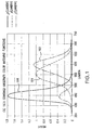
- FIG. 1 illustrates the CIE 1931 x ⁇ , y ⁇ , z ⁇ color matching functions wherein:
- the phrase “printer” refers to any device that includes a printing function.
- the phrase “printer” may refer to an inkjet printer, a laser printer, a commercial printing press, a multifunction peripheral (MFP) that includes a printing function, etc.
- MFP multifunction peripheral
- the phrase “color printer” refers to any type of printer that can generate color printed output.
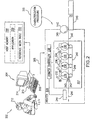
- the computing system 202 includes a host computer 204 and a color printer 206.
- the host computer 204 and the printer 206 are connected via a communication link 208.
- the communication link 208 is a network, such as an intranet for example.
- the host computer 204 includes a central processing unit (CPU) 210, and one or more user interface devices that allow a user (e.g., a user 212) to interact with the host computer 204.
- the one or more user interface devices include, in this example, a display monitor 214 and a keyboard/mouse 216.
- the host computer 204 further includes a memory 218.
- a software application 220 Stored in the host memory 218 is a software application 220 and a reference media table 222.
- the host software application 220 enables a user of the host computer 204 to set-up and then initiate a characterization procedure 205 on the printer 206.
- An example embodiment of the host computer 204 operation while executing the host software application 220 is described below with reference to Fig. 5.
- An example embodiment of the characterization procedure 205 is described below with reference to Fig. 7.
- the reference media table 222 specifies the color of certain preselected "reference" media types that may be used as a "reference medium” in the characterization procedure 205.
- the characterization procedure 205 uses a reference medium to calibrate a colorimeter 244 located within the printer 206. The colorimeter calibration is accomplished immediately prior to using the colorimeter 244 to measure color fields in a characterization target.
- each reference media type included in the table 222 is specified by a set of XYZ tristimulus values.
- the reference media table 222 includes, for example, an entry that specifies the media type known as "HP BRIGHT WHITE PAPER" and a corresponding set of pre-determined XYZ tristimulus values that describe the color of this particular type of print medium.
- the reference media table 222 may include a number of other entries that specify the color of other reference media types that can be used by the characterization procedure 205 to calibrate the colorimeter 244.
- the printer 206 includes various components that enable it to generate printed output.
- the printer 206 includes a print engine 207 that implements an electro-photographic process to generate color printed output.
- the print engine 207 includes apparatus to deposit four differently colored toners onto a sheet of print medium traveling along a media path 246.
- the print engine 207 includes a set of four photoconductive drums 230 one for each color toner employed by the printer 206.
- such colors are Cyan (C), Magenta (M), Yellow (Y) and Black (K).
- Associated with each photoconductive drum 230 is a laser 232, an optics system 234 and a toner developer station cartridge 236.
- the printer 206 further includes, in this example, various other components including a printer controller 238, a media tray 240 capable of holding a stack of print media 241, a media transport system 242, a toner fusing system 243, and the colorimeter 244
- the media transport system 242 enables the printer 206 to pick a sheet from the top of the media stack 241 and to advance the picked sheet along the pre-defined media path 246.
- the media transport system 242 may include a sheet picking device 245 and various other mechanisms (e.g., a transport belt 249) for advancing the picked sheet along the media path 246.
- the printer controller 238 directs the operation of the lasers 232 to place a latent image onto the respective photoconductive drums 230.
- Colored toner e.g., CMY or K
- CMY or K Colored toner obtained from the respective toner developer station cartridges 236 is applied to each respective latent image to create toned latent images.
- the media transport system 242 can pick the top sheet from the media stack 241 and transport the picked sheet through the media path 246. As the sheet is transported along the media path 246, the toned latent images are transferred sequentially to the sheet- thereby creating a multi-color image on the sheet. The multi-color image is then fused to the sheet by the fusing system 243.
- printer 206 The configuration described above of the printer 206 is just one of any number of possible printer configurations and is described only to provide a framework for the following discussion. It is understood that a printer that embodies the invention is not restricted to any particular configuration. For example, a printer that embodies the invention may have more than one media tray.
- printers that do not use an electro-photographic process to generate printed output may embody the invention.
- an inkjet printer and/or a commercial printing press may also embody the invention.
- Fig. 3 illustrates further the printer controller 238 and the colorimeter 244 construction according to an embodiment of the invention.
- the colorimeter 244 includes, in this example, an illuminant source 302 (e.g., a light emitting diode) and a light detector 304 (e.g., a photodiode and an optical filter system).
- an illuminant source 302 e.g., a light emitting diode
- a light detector 304 e.g., a photodiode and an optical filter system
- the colorimeter 244 may be used to measure the color of an area on a sheet of print medium after the area has exited the toner fusing system 246.
- Fig. 3 shows, for example, the colorimeter 244 presently measuring the color of a printed area 319 on a print medium 316 after the printed area 319 has exited the toner fusing system 243.
- the illuminant source 302 produces illumination energy (I source (8)) that is reflected (R(•)) from the printed area 319.
- the reflected energy (after passing through the optical filter system of the colorimeter) is detected by the light detector 304.
- the light detector 304 responds by outputting, to the printer controller 238, a set of XYZ tristimulus values that describe the measured color of the printed area 319.
- the actual color of the printed area 319 may depend upon a number of factors, including the reflectance properties of the one or more colorants used to print the printed area 319 as well as characteristics, such as reflectance characteristics, of the print medium 316.
- the accuracy of the color measurements produced by the colorimeter 244 may degrade over time.
- the output (“/ source ( 8 ) ") of the illuminant source 302 may drift over time thereby introducing error into the color measurements produced by the colorimeter 244.
- colorimeters can be a relatively low cost color measurement device. Additionally, some colorimeters may include a mechanically accessible white reference tile that is used for self calibration. Typically such a reference tile adds cost and needs to be cleaned on a periodic basis to maintain the desired tile reflectance characteristics. As shown below, the colorimeter 244 of the present embodiment may be implemented without a reference tile (thereby saving additional cost) as calibration of the colorimeter 244 can be achieved using a print medium (in place of a mechanical reference tile) as a calibration reference.
- the printer controller 238 includes a processor circuit 306 and a memory 308 each connected to a local bus system 310.
- a printer control module 312 Stored in the memory 308 and executable by the processor 306 to control the operation of the printer 206, is a printer control module 312.
- the printer control module 312 enables the printer 206 to perform the characterization procedure 205 described below.
- the printer memory 308 Also stored in the printer memory 308 is a characterization target 313.
- the characterization target 313 is used by the printer 206 to perform the characterization procedure 205 and includes a number of different color fields each having a known intended color value.
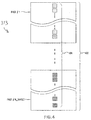
- Fig. 4 illustrates the characterization target 313 as printed on a set of print media sheets 402.
- the printed characterization target 313 includes a set of color fields 404 that span across "N_target" sheets of print media 402, wherein "N_target” represents an integer number of media sheets.
- the color fields 404 are arranged spatially in a column so as to permit the colorimeter 244 to measure each of the printed color fields after exiting the fuser system 243.
- the characterization target 313 may also include registration marks (not shown) that can be sensed by the colorimeter 244. The registration marks may enable the colorimeter/printer controller to determine when a printed color field is at an appropriate location with respect to the colorimeter 244 to permit a color measurement.
- N_Target is a function of the print medium size (e.g., letter or A4) and the printing orientation (e.g., portrait or landscape) that is used to print the characterization target 313. It is noted for the following discussion that this function is known and the host application 220 is able to determine the number of print medium sheets (i.e., N_target) needed to print the target 313 on any given print medium size and print medium orientation.
- Fig. 5 is a flow diagram illustrating an aspect of the host computer 204 operation (as directed by execution of the host application 220) to allow a user 212 to set-up and initiate the printer characterization procedure 205.
- the steps in FIG. 5 are discussed, we will (for illustration purposes) assume that the user 212 desires to define a new color profile for a particular new media type. For ease of discussion, we may refer to this particular new media type as the "target media type".
- the host computer 204 performs some of the steps described below by prompting the user 212 to input certain information or to perform certain other user tasks.
- the host computer 204 may "prompt" a user in any number of ways, such as via a graphical user interface (GUI) or by audio instruction, for example. Additionally, the host computer 204 may enable the user 212 to provide the user input described below in any number of ways including via a GUI or by human voice input, for example.
- GUI graphical user interface
- human voice input for example.
- the host computer 204 receives input from the user 212 that indicates he/she desires a new color profile be created by the printer 206 for a new media type (i.e., the target media type).
- the host computer 204 transmits (over the network 208) a command (off-line command) to the printer 206 to take the printer 206 off line.
- the printer receives and responds to the off-line command by moving to an off-line state (step 508).
- the printer 206 While in an off-line state, the printer 206 does not accept print jobs and waits for a message from the host computer 204 to initiate the characterization procedure 205. Accordingly, after moving into the off-line state and until a message to initiate the characterization procedure 205 is received, the printer 206 will not transport a print medium sheet from the media tray 240. This allows the user 212 to configure the media stack 241 as described below prior to the characterization procedure 205 being initiated.
- the host computer 204 prompts the user to input a name for the target media type (step 510).
- the user 212 responds to this prompt by inputting a custom name (e.g., "Steve's new media") for the target media type (step 512).
- the host computer 204 prompts the user 212 to input certain information with respect to the target media type.
- the host computer 204 prompts the user to input the size of the target media type (e.g., letter or A4) and a preferred printing orientation (e.g., portrait or landscape) for printing the characterization target 313.
- the host computer 204 may also prompt the user to indicate the target media weight and the target media finish at this step.
- the user 212 responds by providing input that specifies the size of the target media type (e.g., letter), the target media weight, the target media finish and a preferred printing orientation (e.g., portrait) for printing the characterization target 313.
- the target media type e.g., letter
- the target media weight e.g., the target media weight
- the target media finish e.g., portrait
- the host computer 204 determines the number (i.e., "N_target") of media sheets of the target media type needed to print the characterization target 313. This determination is based upon the size of the target media type and the preferred printing orientation that was specified (by the user) at step 516. In this example, we will assume that the host computer 204 determines that three media sheets of the target media type are needed to print the characterization target 313.
- the host computer 204 prompts the user to place "N_target” (i.e., three) media sheets of the target media type at the top of the media stack 241.
- the user 212 performs this task and thereby places a set of three media sheets 604 (illustrated below in Fig. 6) of the target media type at the top of the media stack 241.
- the user 212 then provides input to the host computer 204 that indicates he/she has completed this particular task.
- the host computer 204 then prompts the user 212 to select a reference medium type that is listed in the reference media table 222.
- the user 212 selects a reference medium type listed in the table 222 (step 528). In this example, we will assume that the user 212 selects "HP BRIGHT WHITE PAPER" at step 528.
- the host computer 204 prompts the user to place a single sheet (reference sheet) of the user selected reference medium type (i.e. HP BRIGHT WHITE PAPER) at the top of the media stack 241.
- the user 212 performs this task and thereby places a "reference" sheet 602 (illustrated below in Fig. 6) of HP BRIGHT WHITE PAPER at the top of the media stack 241.
- the user 212 then provides input to the host computer 204 that indicates he/she has completed this particular task.
- the host computer 204 At step 536, the host computer 204 generates and then transmits a message 538 to the printer 204 in order to initiate the printer characterization procedure 205.
- the message 538 includes a pre-determined color description (obtained from the reference media table 222) of the selected reference media type.
- the message 538 includes a color description of HP BRIGHT WHITE PAPER.
- the message 538 also includes, in this example, the user specified name of the target media type and the user specified preferred printing orientation of the characterization target 313.
- the message 538 may further include the user specified target media weight and the specified target media finish.
- Shown in Fig. 6 is the media stack 241 configuration at the time when the host computer 204 transmits the message 538 to the printer 206.
- the reference sheet 602 of HP BRIGHT WHITE PAPER is positioned at the top of the media stack 241.
- the set of three sheets 604 are of the target media type and are positioned immediately below the reference sheet 602.
- Fig. 7 is a flow diagram illustrating the operation of the printer 206 to perform the characterization procedure 205 upon receiving the message 538.
- the printer 206 (presently in an off-line state), receives the message 538 from the host computer 204 to initiate the characterization procedure 205. In response to the message 538, the printer 206 operates to first calibrate the colorimeter 244 by performing steps 704-708.
- the printer 206 picks the top sheet (i.e., the reference sheet 602) from the media stack 241 and transports the sheet 602 along the media path 246 to the colorimeter 244.
- the top sheet i.e., the reference sheet 602
- the printer 206 picks the top sheet (i.e., the reference sheet 602) from the media stack 241 and transports the sheet 602 along the media path 246 to the colorimeter 244.
- the printer 206 picks the top sheet (i.e., the reference sheet 602) from the media stack 241 and transports the sheet 602 along the media path 246 to the colorimeter 244.
- the reference sheet 602 passes through the print engine 207.
- the reference sheet 602 is not, however, printed in the present embodiment (although in other embodiments, the reference sheet 602 may indeed be printed).
- the printer 206 uses the colorimeter 244 to measure the color of the reference sheet 602. This results in a color measurement 707 of the reference sheet 602 being generated by the colorimeter 244.
- the color measurement 707 being a set of XYZ tristimulus values.
- the printer 206 calibrates the colorimeter 244 based upon the reference sheet color measurement 707 and the pre-determined color description of HP BRIGHT WHITE PAPER included in the message 538.
- the calibration step may be accomplished, for example, by determining an adjustment to the power applied to the colorimeter illuminant source 302 in order to compensate for drift in the illuminant source output (i.e., " I source (8)").
- the adjusted power is then applied to the colorimeter 244 when subsequent color measurements are performed.
- the colorimeter 244 may be calibrated differently.
- a mathematical normalization may be defined based upon the measured color of the reference sheet 602 and a pre-determined color description of the reference sheet color (e.g., the pre-determined color description of HP BRIGHT WHITE PAPER). The mathematical normalization may then be applied to the subsequent color measurements produced by the colorimeter 244.
- both a power adjustment to the illuminant source 302 and a mathematical normalization is determined and each is applied to subsequent color measurements.
- the printer 206 then proceeds automatically to pick another media sheet (i.e., the first media sheet 606) from the top of the media stack 241 and to transport this sheet along the media path 246 (step 710).
- this sheet is of the target media type.
- the printer 206 prints the first page of color fields in the characterization target 313 onto the first media sheet 606.
- the first page is oriented in accordance with the user specified (characterization target) printing orientation.
- the printer 206 may adjust certain printing parameters based upon the user specified media weight and the user specified media finish that was indicated in the message 538. For example, the printer 206 may set (when printing the characterization target 313) the fusing temperature of the toner fusing system 243 based upon this information.
- the printer 206 measures (using the now calibrated colorimeter 244) the color of each color field printed on the first media sheet 606 and stores these color measurements.
- the printer 206 repeats steps 710-714 so as to:
- the color measurement of each printed color field in the characterization target 313 is used, along with the known intended color of each color field, to define a new color profile 720 for the target media type.
- standard techniques may be used to perform this step.
- "cross-terms” may be used to augment the information included in the color measurements. The use of cross-terms to augment color field measurements is described further in co-pending application number 10/820954, filed April 7, 2004.
- the new color profile 720 is stored in the printer memory 308 under the custom name (e.g., "Steve's new Media") provided by the user 212.
- the printer 206 automatically moves from the off-line state to an on-line state so as to enable users to again use the printer 206 for normal printing.
- the printer 206 defines the color profile 720
- the user 212 can then use the profile to print to the target media type. This can result in improved color reproduction.
- the user 212 may select an option provided by a print driver to use the new color profile 720 when setting up a print job on the host computer 204.
- the host computer 204 In response to the option being selected, the host computer 204 generates a print job that instructs the printer 206 to use the new color profile 720 to map color information included in the job.
- the print job may reference the color profile 720 by the custom name (e.g., Steve's new media) originally provided by the user 212.
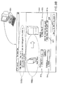
- Fig. 8 shows an example of a computing system 802 according to an embodiment of the invention.
- the computing system 802 includes a host computer 804 operated by a user 805.
- the host computer 804 is connected to a printer 806.
- the printer 806 includes multiple media trays each for holding a supply of print media.
- the printer 806 includes a first media tray (media tray #1) 808 and a second media tray (media tray #2) 810.
- the printer 806 further includes a print engine 812 and a color measurement system 814 for measuring the color of print media after exiting the print engine 812.
- the color measurement system 814 may represent any device capable of measuring print medium color.
- the color measurement system 814 may represent a colorimeter, a densitometer, etc.
- the printer 806 further includes a control system 816 that enables the printer 806 to perform a characterization procedure 817 to define a color profile for a new media type. Similar to the embodiment described above, the characterization procedure 817 uses a reference sheet to calibrate the color measurement system 814 and also involves printing a characterization target 818 on the new media type.
- the host computer 804 includes a computer program (wizard utility 820) that enables the computer 804 to display a wizard graphical user interface (GUI) 830.
- the wizard GUI 830 is for guiding the user 805 through the set-up of the printer characterization procedure 817.
- the wizard GUI 830 enables a user to provide certain input and prompts the user to perform certain tasks associated with the characterization procedure 817.
- FIG. 9A-D shows an example set of dialog boxes according to one embodiment of the wizard GUI 830. Shown in Fig. 9A, for example, is a first dialog box 902 of the Wizard GUI 830.
- the first dialog box 902 includes text 904 that prompts the user to input a custom name for the new media type for which the user wishes to create a profile.
- the user may input the custom name (e.g., Steve's new media) into an input field 906.
- the printer 806 will store the new color profile under this custom name.
- Fig. 9B shows the second dialog box 910 of the Wizard GUI 830.
- the second dialog box 910 includes:
- the second dialog box 910 also prompts the user to place enough sheets (i.e., "N_target") of the new media type in the user selected media tray (e.g., media tray #1) so as to enable the printer 806 to print the characterization target 818 on the new media type.
- N_target is three although in other implementations N_target may be any appropriate value.
- the second dialog box 910 prompts the user to place the new media type in the selected tray via text 918(a) and also by a graphic 918(b).
- the graphic 918(b) conveys graphically (as opposed to textually) the number of sheets that is to be placed in the user selected media tray.
- Fig. 9C shows the third dialog box 930 of the Wizard GUI 830.
- the third dialog box 930 includes:
- the third dialog box 930 also prompts the user to place a single sheet (reference sheet) of the reference media type in the user selected media tray. Note that the third dialog box 930 prompts the user to perform this task by text 942(a) and also by a graphic 942 (b). After the user has performed this task, the user can then select an "Initiate" button 944 to initiate the characterization procedure 817.
- Selecting the initiate button 944 causes the Wizard utility 820 to transmit a message to the printer 806 so as to initiate the characterization procedure 817.
- the message includes the user input specified by the user via the three dialog boxes 902, 910, 930.
- the printer 806 is responsive to the message from the host 804 by performing the characterization procedure 817 in accordance with the user input.
- the printer 806 first calibrates the color measurement system 814 using the top sheet from the media tray selected by the user via input field 934 (dialog box 934).
- this sheet is the reference sheet assuming the user followed the Wizard GUI instructions (i.e., prompt 942(a), 942(b)).
- the printer 806 transports this sheet to the color measurement system 814, measures the color of the sheet and compares the resulting color measurement to a pre-determined reference color description.
- the reference color description being the known color of the reference media type that was selected by the user via input field 932 (dialog box 934). Based upon the comparison, the printer 806 calibrates the color measurement system 814.
- the printer 806 then proceeds to print the characterization target 818 using media sheets obtained from the media tray selected by the user via input field 916 (dialog box 910).
- the reader will note that these sheets are of the new media type assuming the user followed the Wizard GUI instructions (i.e., prompt 918(a), 918(b)).
- the printer 806 uses the calibrated color measurement system 814 to measure each color field printed on these sheets. Based upon these measurements, a new profile is defined for the new media type.
- the present invention may be embodied in the form of a "computer-readable medium".
- computer readable medium can refer to any medium that can contain, store or propagate computer executable instructions.
- computer-readable medium may refer to a medium such as an optical storage device (e.g., a CD ROM) or a magnetic storage device (e.g., a magnetic tape).
- computer-readable medium may also refer to signals that are used to propagate the computer executable instructions over a network or a network system, such as the Public Internet.
- a memory component e.g., the host memory 218 or the printing device memory 308 that stores computer executable instructions (e.g., the set-up utility 220 or the printer control module 312) may represent an embodiment of the invention.
- computer executable instructions e.g., the set-up utility 220 or the printer control module 312
- signals used to propagate the firmware over a communication link e.g. an intranet, Public Internet, etc
- the host computer 204, 804 described above may be moved to another device.
- the reference media table 222 may be located on a remote server or on the printer 206, for example.
- the printer 806 may provide the Wizard GUI (via a local control panel) instead of the host computer 804.
- the host computer (or some other device) may store the characterization target instead of the printer.
Landscapes
- Engineering & Computer Science (AREA)
- Multimedia (AREA)
- Signal Processing (AREA)
- Accessory Devices And Overall Control Thereof (AREA)
- Color Electrophotography (AREA)
- Facsimile Image Signal Circuits (AREA)
- Color Image Communication Systems (AREA)
- Spectrometry And Color Measurement (AREA)
- Color, Gradation (AREA)
Abstract
Description
- There are many different kinds of color input and color output devices. Examples of color input devices include scanners and digital cameras. Examples of color output devices include printers (e.g., inkjet printers, laser printers, offset printers, etc.) and display devices (e.g., CRT devices, video projectors, etc.).
- Because many of these devices can interpret colors differently, device color profiles are often used to enable color information to be accurately shared and reproduced across platforms. A color printer, for example, may make use of a color profile to transform color information into the device's own local color space when printing to a particular target media type. The color profile typically accounts and/or corrects for various characteristics of the color printer as well as the target media type. An example of a standardized color profile format is provided by the International Color Consortium (ICC).
- A characterization procedure is typically performed to define a new color profile for a color printer. A typical characterization procedure, as applied to a color printer, may involve the use of a pre-defined "characterization target" that includes a number of different color fields each having a known intended color value. The printer prints the characterization target onto one or more sheets of a target print media type and the color value of each printed color field is measured. These measurements, along with the known intended color value of each color field, are subsequently used to define a new color profile that corrects for the target print media type. The color profile may be subsequently used by the printer to transform color information into the printer's own local color space when printing to the target media type.
- Unfortunately, performing a characterization procedure to define a new color profile for a printer/media type combination can be both time consuming and complex.
-
- FIG. 1 shows a set of color matching functions;
- Fig. 2 shows an example of a computing system;
- Fig. 3 shows an example of a printer controller;
- Fig. 4 shows an example of a characterization target;
- Fig. 5 is a flow diagram illustrating an aspect of a host computer operation according to one embodiment;
- Fig. 6 shows an example of a media stack;
- Fig. 7 is a flow diagram illustrating an aspect of a printer operation according to one embodiment;
- Fig. 8 shows an example of a computing system; and
- FIG. 9A-C shows an example set of dialog boxes according to one embodiment of a wizard GUI.
- It is understood that a color can be specified by a set of values (typically three or four values) within a defined color space. For purposes of this document a set of values that specify a color within a defined color space may be referred to generally herein as a set of "color components". Thus, for example, a set of RGB values that specifies a color in an RGB color space may alternatively be referred to herein as a set of "color components" or more specifically as a set of "RGB" color components.
- It is also understood that some color spaces can define a color of an object using the following components:
- 1. An illumination I (8) of the object;
- 2. A spectral reflectance R(8) of the object; and
- 3. A set of pre-defined wavelength functions.
- For ease of discussion, a color space that can define a color using these three components may be referred to herein as a "measured color space". The set of pre-defined wavelength functions may generally be referred to herein as the "spectral sensitivity functions" of the color space.
- An example of a measured color space is provided by the Commission International de I'Eclairage (CIE) 1931 standard. This standard defines a color in terms of three color component values that are known as tristimulus values.
- The tristimulus values X, Y and Z may be calculated as follows:



- Wherein the x̅(8), y̅(8) and z̅(8) functions are an example of a set of spectral sensitivity functions. More specifically, these particular functions are known as the CIE 1931 color matching functions or "CMF's".
- For the readers reference, FIG. 1 illustrates the CIE 1931 x̅, y̅, z̅ color matching functions wherein:
-
Curve 102 corresponds to the "x̅ (8)" color matching function; -
Curve 104 corresponds to the "y̅ (8)" color matching function; and -
Curve 106 corresponds to the "z̅ (8)" color matching function. - As used herein, the phrase "printer" refers to any device that includes a printing function. Thus, for example, the phrase "printer" may refer to an inkjet printer, a laser printer, a commercial printing press, a multifunction peripheral (MFP) that includes a printing function, etc. The phrase "color printer" refers to any type of printer that can generate color printed output.
- With reference to Fig. 2, shown is an example of a
computing system 202 according to an embodiment of the present invention. As shown, thecomputing system 202 includes ahost computer 204 and acolor printer 206. Thehost computer 204 and theprinter 206 are connected via acommunication link 208. In this example, thecommunication link 208 is a network, such as an intranet for example. - The
host computer 204 includes a central processing unit (CPU) 210, and one or more user interface devices that allow a user (e.g., a user 212) to interact with thehost computer 204. The one or more user interface devices include, in this example, adisplay monitor 214 and a keyboard/mouse 216. - As shown, the
host computer 204 further includes amemory 218. Stored in thehost memory 218 is asoftware application 220 and a reference media table 222. As discussed further below, thehost software application 220 enables a user of thehost computer 204 to set-up and then initiate acharacterization procedure 205 on theprinter 206. An example embodiment of thehost computer 204 operation while executing thehost software application 220 is described below with reference to Fig. 5. An example embodiment of thecharacterization procedure 205 is described below with reference to Fig. 7. - The reference media table 222 specifies the color of certain preselected "reference" media types that may be used as a "reference medium" in the
characterization procedure 205. As described further below, thecharacterization procedure 205 uses a reference medium to calibrate acolorimeter 244 located within theprinter 206. The colorimeter calibration is accomplished immediately prior to using thecolorimeter 244 to measure color fields in a characterization target. - In this example, the color of each reference media type included in the table 222 is specified by a set of XYZ tristimulus values. The reference media table 222 includes, for example, an entry that specifies the media type known as "HP BRIGHT WHITE PAPER" and a corresponding set of pre-determined XYZ tristimulus values that describe the color of this particular type of print medium. The reference media table 222 may include a number of other entries that specify the color of other reference media types that can be used by the
characterization procedure 205 to calibrate thecolorimeter 244. - The
printer 206 includes various components that enable it to generate printed output. In this example, theprinter 206 includes aprint engine 207 that implements an electro-photographic process to generate color printed output. In this respect, theprint engine 207 includes apparatus to deposit four differently colored toners onto a sheet of print medium traveling along amedia path 246. - In particular, the
print engine 207 includes a set of fourphotoconductive drums 230 one for each color toner employed by theprinter 206. In this example, such colors are Cyan (C), Magenta (M), Yellow (Y) and Black (K). Associated with eachphotoconductive drum 230 is alaser 232, anoptics system 234 and a tonerdeveloper station cartridge 236. - The
printer 206 further includes, in this example, various other components including aprinter controller 238, amedia tray 240 capable of holding a stack ofprint media 241, amedia transport system 242, atoner fusing system 243, and thecolorimeter 244 - The
media transport system 242 enables theprinter 206 to pick a sheet from the top of themedia stack 241 and to advance the picked sheet along thepre-defined media path 246. Accordingly, themedia transport system 242 may include asheet picking device 245 and various other mechanisms (e.g., a transport belt 249) for advancing the picked sheet along themedia path 246. - Generally speaking, in order to print on a sheet of print medium, the
printer controller 238 directs the operation of thelasers 232 to place a latent image onto the respective photoconductive drums 230. Colored toner (e.g., CMY or K) obtained from the respective tonerdeveloper station cartridges 236 is applied to each respective latent image to create toned latent images. - In conjunction with the toned latent images being created, the
media transport system 242 can pick the top sheet from themedia stack 241 and transport the picked sheet through themedia path 246. As the sheet is transported along themedia path 246, the toned latent images are transferred sequentially to the sheet- thereby creating a multi-color image on the sheet. The multi-color image is then fused to the sheet by thefusing system 243. - The configuration described above of the
printer 206 is just one of any number of possible printer configurations and is described only to provide a framework for the following discussion. It is understood that a printer that embodies the invention is not restricted to any particular configuration. For example, a printer that embodies the invention may have more than one media tray. - It is further noted that printers that do not use an electro-photographic process to generate printed output may embody the invention. For example, an inkjet printer and/or a commercial printing press may also embody the invention.
- Fig. 3 illustrates further the
printer controller 238 and thecolorimeter 244 construction according to an embodiment of the invention. Thecolorimeter 244 includes, in this example, an illuminant source 302 (e.g., a light emitting diode) and a light detector 304 (e.g., a photodiode and an optical filter system). - The
colorimeter 244 may be used to measure the color of an area on a sheet of print medium after the area has exited thetoner fusing system 246. Fig. 3 shows, for example, thecolorimeter 244 presently measuring the color of a printedarea 319 on aprint medium 316 after the printedarea 319 has exited thetoner fusing system 243. In this respect, theilluminant source 302 produces illumination energy (Isource (8)) that is reflected (R(•)) from the printedarea 319. - The reflected energy (after passing through the optical filter system of the colorimeter) is detected by the
light detector 304. Thelight detector 304 responds by outputting, to theprinter controller 238, a set of XYZ tristimulus values that describe the measured color of the printedarea 319. - As is appreciated by one skilled in the art, the actual color of the printed
area 319 may depend upon a number of factors, including the reflectance properties of the one or more colorants used to print the printedarea 319 as well as characteristics, such as reflectance characteristics, of theprint medium 316. - For the later discussion, we note that the accuracy of the color measurements produced by the
colorimeter 244 may degrade over time. For example, the output ("/source (8)") of theilluminant source 302 may drift over time thereby introducing error into the color measurements produced by thecolorimeter 244. - As is known in the art, colorimeters can be a relatively low cost color measurement device. Additionally, some colorimeters may include a mechanically accessible white reference tile that is used for self calibration. Typically such a reference tile adds cost and needs to be cleaned on a periodic basis to maintain the desired tile reflectance characteristics. As shown below, the
colorimeter 244 of the present embodiment may be implemented without a reference tile (thereby saving additional cost) as calibration of thecolorimeter 244 can be achieved using a print medium (in place of a mechanical reference tile) as a calibration reference. - As shown in Fig. 3, the
printer controller 238 includes aprocessor circuit 306 and amemory 308 each connected to alocal bus system 310. Stored in thememory 308 and executable by theprocessor 306 to control the operation of theprinter 206, is aprinter control module 312. Theprinter control module 312 enables theprinter 206 to perform thecharacterization procedure 205 described below. - Also stored in the
printer memory 308 is acharacterization target 313. Thecharacterization target 313 is used by theprinter 206 to perform thecharacterization procedure 205 and includes a number of different color fields each having a known intended color value. - Fig. 4 illustrates the
characterization target 313 as printed on a set ofprint media sheets 402. As shown, in this example, the printedcharacterization target 313 includes a set ofcolor fields 404 that span across "N_target" sheets ofprint media 402, wherein "N_target" represents an integer number of media sheets. As is appreciated by a person skilled in the art, the color fields 404 are arranged spatially in a column so as to permit thecolorimeter 244 to measure each of the printed color fields after exiting thefuser system 243. Thecharacterization target 313 may also include registration marks (not shown) that can be sensed by thecolorimeter 244. The registration marks may enable the colorimeter/printer controller to determine when a printed color field is at an appropriate location with respect to thecolorimeter 244 to permit a color measurement. - As is also appreciated by a person skilled in the art, the actual value of "N_Target" is a function of the print medium size (e.g., letter or A4) and the printing orientation (e.g., portrait or landscape) that is used to print the
characterization target 313. It is noted for the following discussion that this function is known and thehost application 220 is able to determine the number of print medium sheets (i.e., N_target) needed to print thetarget 313 on any given print medium size and print medium orientation. - Fig. 5 is a flow diagram illustrating an aspect of the
host computer 204 operation (as directed by execution of the host application 220) to allow auser 212 to set-up and initiate theprinter characterization procedure 205. As the steps in FIG. 5 are discussed, we will (for illustration purposes) assume that theuser 212 desires to define a new color profile for a particular new media type. For ease of discussion, we may refer to this particular new media type as the "target media type". - It is also noted that the
host computer 204 performs some of the steps described below by prompting theuser 212 to input certain information or to perform certain other user tasks. Thehost computer 204 may "prompt" a user in any number of ways, such as via a graphical user interface (GUI) or by audio instruction, for example. Additionally, thehost computer 204 may enable theuser 212 to provide the user input described below in any number of ways including via a GUI or by human voice input, for example. - Beginning at
step 502, thehost computer 204 receives input from theuser 212 that indicates he/she desires a new color profile be created by theprinter 206 for a new media type (i.e., the target media type). - In response to the user input received at
step 502, thehost computer 204 transmits (over the network 208) a command (off-line command) to theprinter 206 to take theprinter 206 off line. The printer receives and responds to the off-line command by moving to an off-line state (step 508). - While in an off-line state, the
printer 206 does not accept print jobs and waits for a message from thehost computer 204 to initiate thecharacterization procedure 205. Accordingly, after moving into the off-line state and until a message to initiate thecharacterization procedure 205 is received, theprinter 206 will not transport a print medium sheet from themedia tray 240. This allows theuser 212 to configure themedia stack 241 as described below prior to thecharacterization procedure 205 being initiated. - In addition to taking the printer off-line, the
host computer 204 prompts the user to input a name for the target media type (step 510). Atstep 512, theuser 212 responds to this prompt by inputting a custom name (e.g., "Steve's new media") for the target media type (step 512). - At
step 514, thehost computer 204 prompts theuser 212 to input certain information with respect to the target media type. In this example, thehost computer 204 prompts the user to input the size of the target media type (e.g., letter or A4) and a preferred printing orientation (e.g., portrait or landscape) for printing thecharacterization target 313. Thehost computer 204 may also prompt the user to indicate the target media weight and the target media finish at this step. - At
step 516, theuser 212 responds by providing input that specifies the size of the target media type (e.g., letter), the target media weight, the target media finish and a preferred printing orientation (e.g., portrait) for printing thecharacterization target 313. - At
step 518, thehost computer 204 determines the number (i.e., "N_target") of media sheets of the target media type needed to print thecharacterization target 313. This determination is based upon the size of the target media type and the preferred printing orientation that was specified (by the user) atstep 516. In this example, we will assume that thehost computer 204 determines that three media sheets of the target media type are needed to print thecharacterization target 313. - At
step 520, thehost computer 204 prompts the user to place "N_target" (i.e., three) media sheets of the target media type at the top of themedia stack 241. Atstep 522, theuser 212 performs this task and thereby places a set of three media sheets 604 (illustrated below in Fig. 6) of the target media type at the top of themedia stack 241. Atstep 524, theuser 212 then provides input to thehost computer 204 that indicates he/she has completed this particular task. - At
step 526, thehost computer 204 then prompts theuser 212 to select a reference medium type that is listed in the reference media table 222. Atstep 528, theuser 212 selects a reference medium type listed in the table 222 (step 528). In this example, we will assume that theuser 212 selects "HP BRIGHT WHITE PAPER" atstep 528. - At
step 530, thehost computer 204 prompts the user to place a single sheet (reference sheet) of the user selected reference medium type (i.e. HP BRIGHT WHITE PAPER) at the top of themedia stack 241. Atstep 532, theuser 212 performs this task and thereby places a "reference" sheet 602 (illustrated below in Fig. 6) of HP BRIGHT WHITE PAPER at the top of themedia stack 241. Atstep 534, theuser 212 then provides input to thehost computer 204 that indicates he/she has completed this particular task. - At
step 536, thehost computer 204 generates and then transmits amessage 538 to theprinter 204 in order to initiate theprinter characterization procedure 205. - The
message 538 includes a pre-determined color description (obtained from the reference media table 222) of the selected reference media type. Thus, in this example, themessage 538 includes a color description of HP BRIGHT WHITE PAPER. Themessage 538 also includes, in this example, the user specified name of the target media type and the user specified preferred printing orientation of thecharacterization target 313. Themessage 538 may further include the user specified target media weight and the specified target media finish. - Shown in Fig. 6 is the
media stack 241 configuration at the time when thehost computer 204 transmits themessage 538 to theprinter 206. As shown, thereference sheet 602 of HP BRIGHT WHITE PAPER is positioned at the top of themedia stack 241. The set of threesheets 604 are of the target media type and are positioned immediately below thereference sheet 602. - Fig. 7 is a flow diagram illustrating the operation of the
printer 206 to perform thecharacterization procedure 205 upon receiving themessage 538. - Beginning at
step 702, the printer 206 (presently in an off-line state), receives themessage 538 from thehost computer 204 to initiate thecharacterization procedure 205. In response to themessage 538, theprinter 206 operates to first calibrate thecolorimeter 244 by performing steps 704-708. - At
step 704, theprinter 206 picks the top sheet (i.e., the reference sheet 602) from themedia stack 241 and transports thesheet 602 along themedia path 246 to thecolorimeter 244. The reader will note that this step leaves the set of threemedia sheets 604 of the target media type now at the top of themedia stack 241. The reader will also note that thereference sheet 602 passes through theprint engine 207. Thereference sheet 602 is not, however, printed in the present embodiment (although in other embodiments, thereference sheet 602 may indeed be printed). - At
step 706, theprinter 206 uses thecolorimeter 244 to measure the color of thereference sheet 602. This results in acolor measurement 707 of thereference sheet 602 being generated by thecolorimeter 244. Thecolor measurement 707 being a set of XYZ tristimulus values. - At
step 708, theprinter 206 calibrates thecolorimeter 244 based upon the referencesheet color measurement 707 and the pre-determined color description of HP BRIGHT WHITE PAPER included in themessage 538. The calibration step may be accomplished, for example, by determining an adjustment to the power applied to thecolorimeter illuminant source 302 in order to compensate for drift in the illuminant source output (i.e., "I source (8)"). The adjusted power is then applied to thecolorimeter 244 when subsequent color measurements are performed. - It is noted that in other embodiments, the
colorimeter 244 may be calibrated differently. For example, according to one embodiment, a mathematical normalization may be defined based upon the measured color of thereference sheet 602 and a pre-determined color description of the reference sheet color (e.g., the pre-determined color description of HP BRIGHT WHITE PAPER). The mathematical normalization may then be applied to the subsequent color measurements produced by thecolorimeter 244. According to yet another embodiment, both a power adjustment to theilluminant source 302 and a mathematical normalization is determined and each is applied to subsequent color measurements. - After the
colorimeter 244 is calibrated, theprinter 206 then proceeds automatically to pick another media sheet (i.e., the first media sheet 606) from the top of themedia stack 241 and to transport this sheet along the media path 246 (step 710). The reader will note that this sheet is of the target media type. - At
step 712, theprinter 206 prints the first page of color fields in thecharacterization target 313 onto thefirst media sheet 606. The first page is oriented in accordance with the user specified (characterization target) printing orientation. Also, theprinter 206 may adjust certain printing parameters based upon the user specified media weight and the user specified media finish that was indicated in themessage 538. For example, theprinter 206 may set (when printing the characterization target 313) the fusing temperature of thetoner fusing system 243 based upon this information. - At
step 714, theprinter 206 measures (using the now calibrated colorimeter 244) the color of each color field printed on thefirst media sheet 606 and stores these color measurements. - The
printer 206 repeats steps 710-714 so as to: - 1. Print the second page of color fields from the
characterization target 313 on thesecond sheet 608. - 2. Measure (using the calibrated colorimeter 244) the color of each color field printed on the
second sheet 608 and to store these color measurements; - 3. Print the third (and final) page of color fields from the
characterization target 313 on thethird media sheet 610; - 4. Measure (using the calibrated colorimeter 244) the color of each color field printed on the
third sheet 610 and to store these color measurements. - At
step 718, the color measurement of each printed color field in thecharacterization target 313 is used, along with the known intended color of each color field, to define anew color profile 720 for the target media type. We note that in some embodiments, standard techniques may be used to perform this step. In other embodiments, "cross-terms" may be used to augment the information included in the color measurements. The use of cross-terms to augment color field measurements is described further in co-pending application number 10/820954, filed April 7, 2004. - At
step 722, thenew color profile 720 is stored in theprinter memory 308 under the custom name (e.g., "Steve's new Media") provided by theuser 212. - At
step 724, after thenew color profile 720 is defined, theprinter 206 automatically moves from the off-line state to an on-line state so as to enable users to again use theprinter 206 for normal printing. - It is noted that after the
printer 206 defines thecolor profile 720, theuser 212 can then use the profile to print to the target media type. This can result in improved color reproduction. - According to one embodiment, the
user 212 may select an option provided by a print driver to use thenew color profile 720 when setting up a print job on thehost computer 204. In response to the option being selected, thehost computer 204 generates a print job that instructs theprinter 206 to use thenew color profile 720 to map color information included in the job. The print job may reference thecolor profile 720 by the custom name (e.g., Steve's new media) originally provided by theuser 212. - Fig. 8 shows an example of a
computing system 802 according to an embodiment of the invention. As shown, thecomputing system 802 includes ahost computer 804 operated by auser 805. Thehost computer 804 is connected to aprinter 806. - The
printer 806 includes multiple media trays each for holding a supply of print media. For example, theprinter 806 includes a first media tray (media tray #1) 808 and a second media tray (media tray #2) 810. - The
printer 806 further includes aprint engine 812 and acolor measurement system 814 for measuring the color of print media after exiting theprint engine 812. Thecolor measurement system 814 may represent any device capable of measuring print medium color. Thus, for example, thecolor measurement system 814 may represent a colorimeter, a densitometer, etc. - The
printer 806 further includes acontrol system 816 that enables theprinter 806 to perform acharacterization procedure 817 to define a color profile for a new media type. Similar to the embodiment described above, thecharacterization procedure 817 uses a reference sheet to calibrate thecolor measurement system 814 and also involves printing acharacterization target 818 on the new media type. - The
host computer 804 includes a computer program (wizard utility 820) that enables thecomputer 804 to display a wizard graphical user interface (GUI) 830. Thewizard GUI 830 is for guiding theuser 805 through the set-up of theprinter characterization procedure 817. In this respect, thewizard GUI 830 enables a user to provide certain input and prompts the user to perform certain tasks associated with thecharacterization procedure 817. - FIG. 9A-D shows an example set of dialog boxes according to one embodiment of the
wizard GUI 830. Shown in Fig. 9A, for example, is afirst dialog box 902 of theWizard GUI 830. Thefirst dialog box 902 includestext 904 that prompts the user to input a custom name for the new media type for which the user wishes to create a profile. The user may input the custom name (e.g., Steve's new media) into aninput field 906. Theprinter 806 will store the new color profile under this custom name. - After the user has typed his/her preferred name for the new media type into the
input field 906, he/she can select a "next"button 908. Selecting the "next"button 908 causes thehost computer 804 to display asecond dialog box 910. - Fig. 9B shows the
second dialog box 910 of theWizard GUI 830. As shown, thesecond dialog box 910 includes: - 1. An
input field 912 that enables a user to specify the size of the new media type (e.g., letter); - 2. An
input field 914 that enables a user to specify a preferred new media type printing orientation (e.g., portrait); - 3. An
input field 916 that enables a user to select a preferred media tray (e.g., media tray #1) to load the new media type for printing of thecharacterization target 818; and - 4. An
input field 917 that allows a user to specify a new media type finish and new media type weight. The reader will note that, in the present embodiment,input field 917 is implemented as a pull down menu. Selecting an arrow 917 (a) results in a pre-determined list of media finish/weight combinations. The user can select the finish/weight combination (e.g., "matte heavy 106-163 g/m2") that he/she believes is closest to the new media type. This information may subsequently be used by theprinter 806 to set various printing parameters when printing thecharacterization target 818. - The
second dialog box 910 also prompts the user to place enough sheets (i.e., "N_target") of the new media type in the user selected media tray (e.g., media tray #1) so as to enable theprinter 806 to print thecharacterization target 818 on the new media type. In the example shown, we again assume N_target is three although in other implementations N_target may be any appropriate value. - The reader will note that the
second dialog box 910 prompts the user to place the new media type in the selected tray via text 918(a) and also by a graphic 918(b). The graphic 918(b) conveys graphically (as opposed to textually) the number of sheets that is to be placed in the user selected media tray. After the user has performed this task, he/she can then select the "next"button 920. Selecting the "next"button 920 causes thehost computer 804 to display athird dialog box 930. - Fig. 9C shows the
third dialog box 930 of theWizard GUI 830. As shown, thethird dialog box 930 includes: - 1. An
input field 932 that enables a user to select a reference media type (e.g., HP BRIGHT WHITE PAPER) from a list of reference types each having a known color; - 2. An
input field 933 that enables a user to specify a size of the selected reference media type (e.g., letter); and - 3. An
input field 934 that enables a user to select the media tray he/she wishes to load a reference sheet of the reference media type. - The
third dialog box 930 also prompts the user to place a single sheet (reference sheet) of the reference media type in the user selected media tray. Note that thethird dialog box 930 prompts the user to perform this task by text 942(a) and also by a graphic 942 (b). After the user has performed this task, the user can then select an "Initiate"button 944 to initiate thecharacterization procedure 817. - Selecting the initiate
button 944 causes theWizard utility 820 to transmit a message to theprinter 806 so as to initiate thecharacterization procedure 817. The message includes the user input specified by the user via the threedialog boxes - The
printer 806 is responsive to the message from thehost 804 by performing thecharacterization procedure 817 in accordance with the user input. In particular, theprinter 806 first calibrates thecolor measurement system 814 using the top sheet from the media tray selected by the user via input field 934 (dialog box 934). The reader will note that this sheet is the reference sheet assuming the user followed the Wizard GUI instructions (i.e., prompt 942(a), 942(b)). Theprinter 806 transports this sheet to thecolor measurement system 814, measures the color of the sheet and compares the resulting color measurement to a pre-determined reference color description. The reference color description being the known color of the reference media type that was selected by the user via input field 932 (dialog box 934). Based upon the comparison, theprinter 806 calibrates thecolor measurement system 814. - The
printer 806 then proceeds to print thecharacterization target 818 using media sheets obtained from the media tray selected by the user via input field 916 (dialog box 910). The reader will note that these sheets are of the new media type assuming the user followed the Wizard GUI instructions (i.e., prompt 918(a), 918(b)). Theprinter 806 uses the calibratedcolor measurement system 814 to measure each color field printed on these sheets. Based upon these measurements, a new profile is defined for the new media type. - It is further noted that the present invention may be embodied in the form of a "computer-readable medium". As used herein, the phrase "computer readable medium" can refer to any medium that can contain, store or propagate computer executable instructions. Thus, in this document, the phrase "computer-readable medium" may refer to a medium such as an optical storage device (e.g., a CD ROM) or a magnetic storage device (e.g., a magnetic tape). The phrase "computer-readable medium" may also refer to signals that are used to propagate the computer executable instructions over a network or a network system, such as the Public Internet.
- Thus, a memory component (e.g., the
host memory 218 or the printing device memory 308) that stores computer executable instructions (e.g., the set-uputility 220 or the printer control module 312) may represent an embodiment of the invention. Furthermore, signals used to propagate the firmware over a communication link (e.g. an intranet, Public Internet, etc) may also represent an embodiment of the invention. - Although several specific embodiments of the invention have been described and illustrated, the invention is not to be limited to specific forms or arrangements of parts so described and illustrated. For example, some or all of the functionality of the
host computer printer 206, for example. Also, theprinter 806 may provide the Wizard GUI (via a local control panel) instead of thehost computer 804. Also, in various implementations, the host computer (or some other device) may store the characterization target instead of the printer. - The invention is limited only by the claims and the equivalents thereof.
Claims (10)
- A method for a printer that includes a color measurement system, the method comprising:picking a reference sheet of a first media type from a stack of media contained in a first media tray (704);transporting the reference sheet to the color measurement system (704);measuring, by use of the color measurement system, a color of the reference sheet (706); andusing the measured color of the reference sheet and a pre-determined description of the reference sheet color to calibrate the color measurement system (708).
- The method of claim 1, further comprising:immediately following the calibration of the color measurement system, automatically performing steps in a characterization procedure to define a color profile for use when printing to a second media type.
- The method of claim 1, further comprising:immediately following the calibration of the color measurement system, automatically printing a set of color fields onto a second sheet of a second media type (712);using the calibrated color measurement system to measure each of the color fields printed on the second sheet so as to generate a set of color field measurements (714);using the set of color field measurements to define a color profile for use when printing to the second media type (718).
- The method of claim 3, wherein the printing step obtains the second sheet of the second media type from the stack of media contained in the first media tray.
- The method of claim 3, wherein the printing step obtains the second sheet of the second media type from a stack of media contained in a second media tray.
- The method according to any of claims 2 to 5, wherein the first media type is different than the second media type.
- The method according to any of the above claims, wherein the method is performed while the printer is in an off-line state (508).
- The method of claim 1, further comprising:after the color measurement system is calibrated, automatically performing a characterization procedure to define a color profile for use when printing to a second media type; andstoring the color profile (722).
- The method of claim 8, wherein performing the characterization procedure includes:picking a second sheet of the second media type from the stack of media contained in the first media tray (710);printing a set of color fields on the second sheet (712); andusing the calibrated color measurement system to measure each of the color fields printed on the second sheet (718).
- The method according to any of the above claims, wherein the color measurement system is a colorimeter (244).
Applications Claiming Priority (1)
| Application Number | Priority Date | Filing Date | Title |
|---|---|---|---|
| US11/046,056 US7619771B2 (en) | 2005-01-28 | 2005-01-28 | Color calibration in a printer |
Publications (3)
| Publication Number | Publication Date |
|---|---|
| EP1699226A2 true EP1699226A2 (en) | 2006-09-06 |
| EP1699226A3 EP1699226A3 (en) | 2007-12-05 |
| EP1699226B1 EP1699226B1 (en) | 2012-05-02 |
Family
ID=36608681
Family Applications (1)
| Application Number | Title | Priority Date | Filing Date |
|---|---|---|---|
| EP06100939A Expired - Lifetime EP1699226B1 (en) | 2005-01-28 | 2006-01-27 | Method for calibrating a printer |
Country Status (3)
| Country | Link |
|---|---|
| US (1) | US7619771B2 (en) |
| EP (1) | EP1699226B1 (en) |
| JP (1) | JP2006211665A (en) |
Families Citing this family (11)
| Publication number | Priority date | Publication date | Assignee | Title |
|---|---|---|---|---|
| JP4766672B2 (en) * | 2005-11-01 | 2011-09-07 | キヤノン株式会社 | Information processing apparatus, printing apparatus, information processing apparatus control method, printing apparatus control method, and program |
| US8203749B2 (en) * | 2006-06-16 | 2012-06-19 | Hewlett-Packard Development Company, L.P. | Printing device, carriage and color measurement method |
| JP4269182B2 (en) * | 2006-10-18 | 2009-05-27 | セイコーエプソン株式会社 | Printing color measurement control device, printing color measurement control method, printing color measurement control program, and printing apparatus |
| US7969624B2 (en) * | 2006-12-11 | 2011-06-28 | Xerox Corporation | Method and system for identifying optimal media for calibration and control |
| JP4420086B2 (en) * | 2007-08-23 | 2010-02-24 | コニカミノルタビジネステクノロジーズ株式会社 | Image forming apparatus and image forming system |
| JP5990093B2 (en) * | 2012-11-29 | 2016-09-07 | キヤノン株式会社 | Image processing apparatus, image processing method, and program |
| US20140178084A1 (en) * | 2012-12-21 | 2014-06-26 | Hewlett-Packard Development Company, L.P. | Machine learning based tone consistency calibration decisions |
| US9195916B1 (en) * | 2014-06-05 | 2015-11-24 | Electronics For Imaging, Inc. | Color prediction for color printing |
| JP6459488B2 (en) | 2014-12-22 | 2019-01-30 | セイコーエプソン株式会社 | Printing device |
| JP2016118468A (en) * | 2014-12-22 | 2016-06-30 | セイコーエプソン株式会社 | Colorimetry device and printer |
| US9868311B2 (en) | 2015-05-18 | 2018-01-16 | The Procter & Gamble Company | In-line case printing system with dynamic sampling frequency and method therefor |
Family Cites Families (14)
| Publication number | Priority date | Publication date | Assignee | Title |
|---|---|---|---|---|
| US5182721A (en) * | 1985-12-10 | 1993-01-26 | Heidelberger Druckmaschinen Aktiengesellschaft | Process and apparatus for controlling the inking process in a printing machine |
| DE69115523T2 (en) * | 1990-03-01 | 1996-06-13 | X Rite Inc | Compensation method for use in color measuring devices |
| US5781206A (en) * | 1995-05-01 | 1998-07-14 | Minnesota Mining And Manufacturing Company | Apparatus and method for recalibrating a multi-color imaging system |
| US7280251B1 (en) * | 1996-02-26 | 2007-10-09 | Rah Color Technologies | System and method for calibrating color printers |
| JP2001045295A (en) | 1999-08-03 | 2001-02-16 | Canon Inc | Image processing apparatus and correction information generation method thereof |
| US7173724B2 (en) * | 2001-02-02 | 2007-02-06 | Sharp Kabushiki Kaisha | Image forming system having display sections with different formats |
| JP2005506911A (en) * | 2001-02-21 | 2005-03-10 | アグフア−ゲヴエルト,ナームローゼ・フエンノートシヤツプ | Method and system for managing color quality of output device |
| US6676316B2 (en) * | 2001-08-28 | 2004-01-13 | Eastman Kodak Company | Media cassette having an identification device for identifying the type of media in the cassette, and an imaging apparatus having said media cassette |
| DE60229338D1 (en) * | 2001-09-07 | 2008-11-27 | Canon Kk | Image processing method and apparatus |
| US7068380B2 (en) * | 2001-12-21 | 2006-06-27 | Microsoft Corporation | Print media catalog service |
| JP3880510B2 (en) * | 2002-01-24 | 2007-02-14 | キヤノン株式会社 | Recording apparatus and recording medium type discrimination method |
| JP4293767B2 (en) * | 2002-08-30 | 2009-07-08 | シャープ株式会社 | Image forming control method and image forming apparatus |
| JP3753126B2 (en) * | 2002-11-29 | 2006-03-08 | ブラザー工業株式会社 | Medium edge detection device and image forming apparatus |
| JP2004320627A (en) * | 2003-04-18 | 2004-11-11 | Seiko Epson Corp | Correspondence definition data creation grid point determination system, correspondence definition data creation grid point request client, correspondence relation definition data creation grid point determination server, method and program |
-
2005
- 2005-01-28 US US11/046,056 patent/US7619771B2/en not_active Expired - Fee Related
-
2006
- 2006-01-25 JP JP2006015932A patent/JP2006211665A/en active Pending
- 2006-01-27 EP EP06100939A patent/EP1699226B1/en not_active Expired - Lifetime
Also Published As
| Publication number | Publication date |
|---|---|
| EP1699226A3 (en) | 2007-12-05 |
| EP1699226B1 (en) | 2012-05-02 |
| US20060170991A1 (en) | 2006-08-03 |
| JP2006211665A (en) | 2006-08-10 |
| US7619771B2 (en) | 2009-11-17 |
Similar Documents
| Publication | Publication Date | Title |
|---|---|---|
| US11831847B2 (en) | Image processing apparatus, image processing method, and program for forming correcting color image data for each paper type | |
| US8743407B2 (en) | Computer readable recording medium stored with color conversion setting program, color conversion setting method, computer readable recording medium stored with color conversion processing program, and color conversion processing apparatus that enables configuration of color conversion profiles when using various types of paper in a print job | |
| US9057646B2 (en) | Image forming apparatus for measuring a color of a measurement image | |
| JP4447887B2 (en) | Color image forming apparatus and color stabilization control method | |
| US10782639B2 (en) | Measurement apparatus, image forming apparatus and image forming system | |
| JP7229782B2 (en) | Measuring device and image forming system | |
| JP6624842B2 (en) | Image forming device | |
| US10148828B2 (en) | Image forming apparatus, image forming system, and non-transitory recording medium storing a computer readable program | |
| EP1699226B1 (en) | Method for calibrating a printer | |
| JP2017039278A (en) | Image forming apparatus | |
| JP2012169888A (en) | Color adjustment method and image forming system | |
| US9229405B2 (en) | Image forming apparatus | |
| US10078012B2 (en) | Measurement apparatus with adjustment for spectral shift | |
| US10401771B2 (en) | Image forming apparatus and control method which generates color processing condition | |
| US8514470B2 (en) | Digital printing control using a spectrophotometer | |
| JP2017041796A (en) | Image forming apparatus | |
| JP2013080181A (en) | Image forming apparatus | |
| JP5253602B2 (en) | Image output apparatus and image output method | |
| JP2020046517A (en) | Measuring device, image forming device, and image forming system | |
| US20070019026A1 (en) | Printer | |
| JP6450444B2 (en) | Measuring apparatus and image forming apparatus | |
| JP2014116694A (en) | Image processing apparatus, image processing method, and program for performing the image processing method |
Legal Events
| Date | Code | Title | Description |
|---|---|---|---|
| PUAI | Public reference made under article 153(3) epc to a published international application that has entered the european phase |
Free format text: ORIGINAL CODE: 0009012 |
|
| AK | Designated contracting states |
Kind code of ref document: A2 Designated state(s): AT BE BG CH CY CZ DE DK EE ES FI FR GB GR HU IE IS IT LI LT LU LV MC NL PL PT RO SE SI SK TR |
|
| AX | Request for extension of the european patent |
Extension state: AL BA HR MK YU |
|
| PUAL | Search report despatched |
Free format text: ORIGINAL CODE: 0009013 |
|
| AK | Designated contracting states |
Kind code of ref document: A3 Designated state(s): AT BE BG CH CY CZ DE DK EE ES FI FR GB GR HU IE IS IT LI LT LU LV MC NL PL PT RO SE SI SK TR |
|
| AX | Request for extension of the european patent |
Extension state: AL BA HR MK YU |
|
| 17P | Request for examination filed |
Effective date: 20080521 |
|
| 17Q | First examination report despatched |
Effective date: 20080623 |
|
| AKX | Designation fees paid |
Designated state(s): DE FR GB |
|
| GRAP | Despatch of communication of intention to grant a patent |
Free format text: ORIGINAL CODE: EPIDOSNIGR1 |
|
| RTI1 | Title (correction) |
Free format text: METHOD FOR CALIBRATING A PRINTER |
|
| GRAS | Grant fee paid |
Free format text: ORIGINAL CODE: EPIDOSNIGR3 |
|
| GRAA | (expected) grant |
Free format text: ORIGINAL CODE: 0009210 |
|
| AK | Designated contracting states |
Kind code of ref document: B1 Designated state(s): DE FR GB |
|
| REG | Reference to a national code |
Ref country code: GB Ref legal event code: FG4D |
|
| REG | Reference to a national code |
Ref country code: DE Ref legal event code: R096 Ref document number: 602006029188 Country of ref document: DE Effective date: 20120712 |
|
| PLBE | No opposition filed within time limit |
Free format text: ORIGINAL CODE: 0009261 |
|
| STAA | Information on the status of an ep patent application or granted ep patent |
Free format text: STATUS: NO OPPOSITION FILED WITHIN TIME LIMIT |
|
| 26N | No opposition filed |
Effective date: 20130205 |
|
| REG | Reference to a national code |
Ref country code: DE Ref legal event code: R097 Ref document number: 602006029188 Country of ref document: DE Effective date: 20130205 |
|
| REG | Reference to a national code |
Ref country code: FR Ref legal event code: PLFP Year of fee payment: 10 |
|
| PGFP | Annual fee paid to national office [announced via postgrant information from national office to epo] |
Ref country code: GB Payment date: 20141219 Year of fee payment: 10 |
|
| PGFP | Annual fee paid to national office [announced via postgrant information from national office to epo] |
Ref country code: DE Payment date: 20141218 Year of fee payment: 10 |
|
| PGFP | Annual fee paid to national office [announced via postgrant information from national office to epo] |
Ref country code: FR Payment date: 20150121 Year of fee payment: 10 |
|
| REG | Reference to a national code |
Ref country code: DE Ref legal event code: R119 Ref document number: 602006029188 Country of ref document: DE |
|
| GBPC | Gb: european patent ceased through non-payment of renewal fee |
Effective date: 20160127 |
|
| REG | Reference to a national code |
Ref country code: FR Ref legal event code: ST Effective date: 20160930 |
|
| PG25 | Lapsed in a contracting state [announced via postgrant information from national office to epo] |
Ref country code: DE Free format text: LAPSE BECAUSE OF NON-PAYMENT OF DUE FEES Effective date: 20160802 Ref country code: GB Free format text: LAPSE BECAUSE OF NON-PAYMENT OF DUE FEES Effective date: 20160127 |
|
| PG25 | Lapsed in a contracting state [announced via postgrant information from national office to epo] |
Ref country code: FR Free format text: LAPSE BECAUSE OF NON-PAYMENT OF DUE FEES Effective date: 20160201 |