EP1698705A2 - Process and installation for the addition of a manganese alloy during steel processing - Google Patents
Process and installation for the addition of a manganese alloy during steel processing Download PDFInfo
- Publication number
- EP1698705A2 EP1698705A2 EP06003578A EP06003578A EP1698705A2 EP 1698705 A2 EP1698705 A2 EP 1698705A2 EP 06003578 A EP06003578 A EP 06003578A EP 06003578 A EP06003578 A EP 06003578A EP 1698705 A2 EP1698705 A2 EP 1698705A2
- Authority
- EP
- European Patent Office
- Prior art keywords
- steel
- manganese
- strand
- ladle
- tube
- Prior art date
- Legal status (The legal status is an assumption and is not a legal conclusion. Google has not performed a legal analysis and makes no representation as to the accuracy of the status listed.)
- Withdrawn
Links
Images

Classifications
-
- C—CHEMISTRY; METALLURGY
- C21—METALLURGY OF IRON
- C21C—PROCESSING OF PIG-IRON, e.g. REFINING, MANUFACTURE OF WROUGHT-IRON OR STEEL; TREATMENT IN MOLTEN STATE OF FERROUS ALLOYS
- C21C7/00—Treating molten ferrous alloys, e.g. steel, not covered by groups C21C1/00 - C21C5/00
- C21C7/0006—Adding metallic additives
-
- B—PERFORMING OPERATIONS; TRANSPORTING
- B22—CASTING; POWDER METALLURGY
- B22D—CASTING OF METALS; CASTING OF OTHER SUBSTANCES BY THE SAME PROCESSES OR DEVICES
- B22D1/00—Treatment of fused masses in the ladle or the supply runners before casting
-
- C—CHEMISTRY; METALLURGY
- C21—METALLURGY OF IRON
- C21C—PROCESSING OF PIG-IRON, e.g. REFINING, MANUFACTURE OF WROUGHT-IRON OR STEEL; TREATMENT IN MOLTEN STATE OF FERROUS ALLOYS
- C21C7/00—Treating molten ferrous alloys, e.g. steel, not covered by groups C21C1/00 - C21C5/00
- C21C7/0037—Treating molten ferrous alloys, e.g. steel, not covered by groups C21C1/00 - C21C5/00 by injecting powdered material
-
- C—CHEMISTRY; METALLURGY
- C21—METALLURGY OF IRON
- C21C—PROCESSING OF PIG-IRON, e.g. REFINING, MANUFACTURE OF WROUGHT-IRON OR STEEL; TREATMENT IN MOLTEN STATE OF FERROUS ALLOYS
- C21C7/00—Treating molten ferrous alloys, e.g. steel, not covered by groups C21C1/00 - C21C5/00
- C21C7/0056—Treating molten ferrous alloys, e.g. steel, not covered by groups C21C1/00 - C21C5/00 using cored wires
-
- F—MECHANICAL ENGINEERING; LIGHTING; HEATING; WEAPONS; BLASTING
- F27—FURNACES; KILNS; OVENS; RETORTS
- F27D—DETAILS OR ACCESSORIES OF FURNACES, KILNS, OVENS OR RETORTS, IN SO FAR AS THEY ARE OF KINDS OCCURRING IN MORE THAN ONE KIND OF FURNACE
- F27D3/00—Charging; Discharging; Manipulation of charge
- F27D3/0033—Charging; Discharging; Manipulation of charge charging of particulate material
Definitions
- the invention relates to a method and a device for feeding, at least one manganese alloy in steel production according to the preamble of claim 1.
- manganese alloys (ferromanganese with high, medium and low carbon content, manganese with normal and low carbon content) containing manganese in the range of 50 to 90% and a carbon content of 0.05 to 7.0% supplied; the manganese alloys serve as deoxidizing and binding agents.
- the process currently used in steel mills to add this material to the primary steel is extremely simple and has been known for a long time. It consists in adding said alloys in the form of blocks of different size with usual dimensions of 5 to 30 mm, 10 to 50 mm, 10 to 60 mm, 20 to 80 mm and 25 to 100 mm.
- the blocks are taken from the transport vehicle in the steelworks and piled up in warehouses. They are then or the like by conveyor belts, forklifts. Transported transport equipment to the feeders and then added before the relevant chemical analysis of the so-called primary steel - in the required amount of a ladle for receiving the primary steel while it is tapped from a thermal container in this. The material is poured into the ladle during the tapping of the primary steel resulting from the steelmaking, regardless of the type of process used to make the primary steel and the subsequent fine tuning.
- the inventor has set the goal to achieve an improvement of the method described above, and in particular to find a method that reduces the addition of the mentioned gases in the addition.
- the enhancements are designed to optimize practical operations, make more efficient use of the technology, and reduce the impact on the environment.
- the amount of manganese required to treat the steel should be able to be added with greater precision.
- the addition of the manganese alloy (s) in the form of high medium and low carbon ferromanganese, normal and low carbon manganese silicon occurs during tapping of the glowing mass of a primary steel containing iron material and melt aggregates into a ladle; preferred is a content of manganese in the range of about 50% to 90% and a carbon content of about 0.05 to 7.0%. It has proved to be beneficial to introduce the manganese alloys in particles of the order of 0 to 5 mm.
- the manganese alloy - a preferred grain size of about 5 mm - in the interior of a tubular container made of a resistant to heat for a certain time material, in particular steel sheet, which gradually introduced into the interior of that glowing mass which is closed and advantageously has a circular cross-section.
- tubular shapes such a tubular container or sleeve strand of sheet steel and introduce with its free end in the primary steel; he should in particular be pushed by a pusher into the ladle, wherein the free end portion of the tube-like sleeve strand is melted at a relatively great distance from the metal mirror.
- the interior of the ladle for the primary steel as a container for at least one granular manganese alloy is associated with a sleeve strand, which consists of a limited flexible steel tube.
- the latter is to consist of a sheet steel strip whose two longitudinal edges are arranged rectified at a sealing fold next to each other, wherein the one cross-sectional end of the sheet steel strip unfolded as a short strip and placed on the outside of the sheet steel strip and the inside is applied to the other cross-sectional end portion.
- the above-mentioned circular cross-section of the steel tube of the sleeve strand offers a diameter of at least 21 mm with a small wall thickness of about 0.3 mm to 1.0 mm.
- the sleeve strand advantageously forms a roller placed around a central axis, from which it is led out by a pulling or pushing device and its free end is introduced into the ladle.
- This pusher contains several pairs of small rolls, between which the pigtail is pulled pulled.
- the large roll from the sleeve strand preferably rests on a bottom frame of a receiving device, to which the central axis of the roll extends parallel or at right angles.
- a scaffold for the role of the sleeve strand which contains according to the invention at one end connected to the bottom frame holding profiles.
- the latter can be connected to one another by at least one transverse arm.
- this scaffold or with this on the floor frame to arrange longitudinal profiles for the roll to be stored on them.
- a sleeve strand 10 is sketched round cross-section of an outer diameter d of slightly more than 21 mm, the wall 12 of small thickness f, for example, 0.3 mm to 1.00 mm of sheet steel is tubular shaped; the two longitudinal edges 16 of the sheet steel strip 14 are arranged to form a fold 18 rectified side by side and may optionally be connected to each other by a binder, such as a weld.
- the one cross-sectional end of the sheet steel strip 14 is unfolded as a short strip 15 and externally placed on the sheet steel strip 14 and the inside applied to the other cross-sectional end portion.
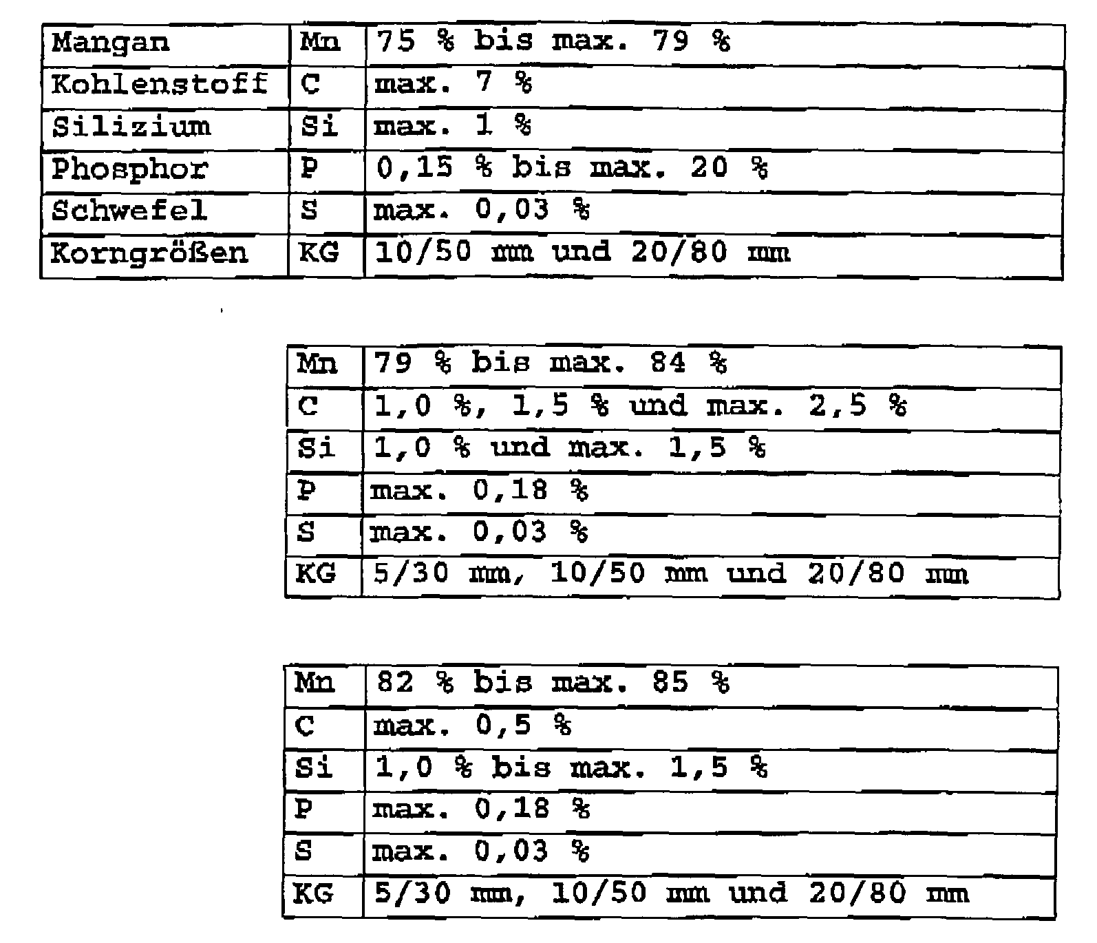
- the sleeve strand 10 receives a milled manganese alloy 20, whose grains offer a grain size e up to 5 mm.
- preferred alloys have the following compositions:
- the plant outlined in Fig. 2 includes a receiving and transporting means 22 for the wound-up tube strand 10, which wound up under determination of a central axis M in this role as R - superimposed and by pairs of small rollers 24 a pusher or Injizierstation 26 in the direction of movement x from the Coil or receiving device 22 is pulled.
- the free strand end 11 of the sleeve strand 10 dives into the interior 28 of a ladle 30. This is supplied in the direction of arrow y, a primary beam Q, which is taken from a converter, not shown; The latter have been abandoned pig iron and Schmelzzudite to produce there by the introduction of oxygen that primary beam Q.
- the free strand end 11 of the immersed sleeve strand 10 melts in a relatively large distance i to the metal mirror 29, which extends below the upper edge 31 of the ladle 30.
- Another method of producing the primary jet Q is realized by the use of electric melting furnaces having three electrodes of graphite material at which electric current is generated in a refractory-lined shaft against the charge of the raw materials; These are generally scrap, sponge iron and smelters.
- the primary jet Q is - as I said - the ladle 30 fed. During this process, the addition of said alloys takes place.
- the pushing device or adding station 26 presses the free end of the sleeve strand 10 filled with the manganese alloy 20 at a controllable speed into the ladle 30, which additionally receives or already contains the liquid primary jet Q from the tapping.
- This arrangement has the advantage that the active length of the sleeve strand 10 can be metered via systems controlled by the operating personnel.
- the latter determines - as soon as one knows the chemical analysis of the primary beam Q to be treated - by calculation the amount of manganese alloy 20 which must be added, expressed in terms of the number of meters of barrel strand 10 fed into the ladle 30. In some cases the system is programmatically and performs that calculation automatically.
- the receiving device 22 here consists of a - metal or wooden profiles 32 containing - bottom frame 34 and one of them towering support frame 36 from the bottom frame 34 on both sides of - resting on longitudinal profiles 35 - R role upstanding retaining profiles 37, which are connected in Fig. 2, 4 by transverse profiles 38 for the roller R of the sleeve strand 10.
- the central axis M of that roller R is horizontal, in the receiving device 22 a of FIG. 5, however vertical; missing here on the support frame 36 a in this application unnecessary cross sections.
- the manganese alloy 20 and other components are thus fed into the primary stream Q during the tapping into the ladle 30 by means of the sleeve strand 10 as a tubular container.
- the latter is made of a material that has a certain resistance to high temperatures due to its intrinsic properties.
- the sleeve strand 10, also referred to as a sleeve is produced on special machines and then brought to the place of use as roll R, as stated.
- the starting material used is strip steel, which is given a U-shape in several successive steps of form-fitting bending.
- the milled manganese alloy 20 is fed to the casing 10 precisely dimensioned with respect to the weight of the alloy now contained, expressed in grams per meter.
- the steel sheet tube is closed from sheet steel strip 14.
- the resulting tubular product is rolled up like a cable in the manner described above.
- the resulting and filled coil or reel R then stored in the receiving device 22, which can accommodate between 1,000 meters and 5,000 meters of the sleeve strand 10 and can be easily transported with mobile hoists for loads of at least 2.5 tons. Storage must take place in covered rooms.
- the casing 10 thanks to its tubular casing of the sheet steel strip 14 for a short time resists the temperatures prevailing inside the ladle 30 without dissolving, allows it to penetrate into the lower zones of the ladle 30. In this way, the addition takes place in the innermost of the amount of liquid steel, which means that the material is used more efficiently in the steel bath and surface reactions are avoided.
Landscapes
- Chemical & Material Sciences (AREA)
- Engineering & Computer Science (AREA)
- Materials Engineering (AREA)
- Metallurgy (AREA)
- Organic Chemistry (AREA)
- Mechanical Engineering (AREA)
- General Engineering & Computer Science (AREA)
- Treatment Of Steel In Its Molten State (AREA)
Abstract
Bei einem Verfahren zur Zuführung von zumindest einer Manganlegierung zu einem Stahlmaterial bei der Stahlerzeugung, werden der glühenden Masse eines Primärstahles (Q) während dessen Abstiches in eine Gießpfanne (30) die Manganlegierungen in Form von Ferromangan einer bevorzugten Korngröße bis etwa 5 mm mit hohem, mittlerem und niedrigem Kohlenstoffanteil, Mangansilizium mit normalem und niedrigem Kohlenstoffgehalt zugegeben. Die Manganlegierung wird in einem röhrenförmigen, schlauchartig aus Stahlblech geformten Behälter (10) aus einem Werkstoff mit Widerstandsfähigkeit gegen hohe Temperaturen zugeführt und dieser Behälter oder Hülsenstrang (10) mit seinem freien Ende in das Innere der glühenden Masse eingeleitet.In a method for supplying at least one manganese alloy to a steel material in steelmaking, the glowing mass of a primary steel (Q) during its tapping into a ladle (30) the manganese alloys in the form of ferromanganese with a preferred grain size up to about 5 mm with high, medium and low carbon content, normal and low carbon manganese silicon added. The manganese alloy is supplied in a tubular tube-shaped steel sheet-shaped container (10) made of a material having high-temperature resistance, and this container or sleeve strand (10) is introduced with its free end into the interior of the glowing mass.
Die Stahlblechröhre des Hülsenstranges (10) besteht aus einem Stahlblechstreifen (14), dessen beide Längskanten (16) an einem dichten Falz (18) gleichgerichtet nebeneinander angeordnet sind.The sheet steel tube of the sleeve strand (10) consists of a steel strip (14), the two longitudinal edges (16) on a tight fold (18) rectified are arranged side by side.
Es wird eine Vorrichtung eingesetzt, bei der dem Innenraum (28) einer Gießpfanne (30) für den Primärstahl (Q) der Hülsenstrang (10) zugeordnet ist. Letzterer bildet eine um eine Mittelachse (M) gelegte Wickelrolle (R), von der aus er durch mehrere Paare (24) von Rollen einer Schubeinrichtung (26) geführt und sein freies Ende (11) in die Gießpfanne (30) eingebracht ist.

Description
Die Erfindung betrifft ein Verfahren sowie eine Vorrichtung zur Zuführung von, zumindest einer Manganlegierung bei der Stahlerzeugung nach dem Oberbegriff des Patentanspruches 1.The invention relates to a method and a device for feeding, at least one manganese alloy in steel production according to the preamble of claim 1.
Bisher wird beim Herstellen von Bau- und Sonderstahl ein Zusatz von Manganlegierungen (Ferromangan mit hohem, mittlerem und niedrigem Kohlenstoffanteil, Mangansilizium mit normalem und niedrigem Kohlenstoffanteil) mit einem Gehalt an Mangan im Bereich von 50 bis 90 % sowie einem Kohlenstoffgehalt von 0,05 bis 7,0 % zugeführt; die Manganlegierungen dienen als Desoxidations- und Bindemittel.So far, in the manufacture of structural and special steel, an addition of manganese alloys (ferromanganese with high, medium and low carbon content, manganese with normal and low carbon content) containing manganese in the range of 50 to 90% and a carbon content of 0.05 to 7.0% supplied; the manganese alloys serve as deoxidizing and binding agents.
Das gegenwärtig in Stahlwerken angewendete Verfahren der Zugabe dieses Materials zur Behandlung des Primärstahls ist äußerst einfach und bereits sehr lange bekannt. Es besteht darin, dass die genannten Legierungen in der Form von Klötzchen unterschiedlichen Formats mit üblichen Abmessungen von 5 bis 30 mm, 10 bis 50 mm, 10 bis 60 mm, 20 bis 80 mm und 25 bis 100 mm zugegeben werden.The process currently used in steel mills to add this material to the primary steel is extremely simple and has been known for a long time. It consists in adding said alloys in the form of blocks of different size with usual dimensions of 5 to 30 mm, 10 to 50 mm, 10 to 60 mm, 20 to 80 mm and 25 to 100 mm.
Die Klötzchen werden im Stahlwerk dem Transportfahrzeug entnommen und in Lagern aufgehäuft. Sie werden dann durch Förderbänder, Gabelstapler od.dgl. Transportgeräte zu den Beschickungsvorrichtungen transportiert und anschließendvor der einschlägigen chemischen Analyse des sogenannten Primärstahls -- in der erforderlichen Menge einer Gießpfanne zur Aufnahme des Primärstahls zugegeben, während er aus einem Thermobehälter in diese abgestochen wird. Das Material wird während des Abstichs des Primärstahls, der aus der Stahlherstellung resultiert, in die Gießpfanne geschüttet und zwar unabhängig von der Art des zur Herstellung des Primärstahls angewendeten Prozesses und der nachfolgenden Feinabstimmung.The blocks are taken from the transport vehicle in the steelworks and piled up in warehouses. They are then or the like by conveyor belts, forklifts. Transported transport equipment to the feeders and then added before the relevant chemical analysis of the so-called primary steel - in the required amount of a ladle for receiving the primary steel while it is tapped from a thermal container in this. The material is poured into the ladle during the tapping of the primary steel resulting from the steelmaking, regardless of the type of process used to make the primary steel and the subsequent fine tuning.
Während das Mangan in der beschriebenen Weise zugegeben wird, erfolgt an der Oberfläche der Gießpfanne die Bildung von Gasen in bedeutenden Mengen. Jüngere Studien in den Vereinigten Staaten von Amerika haben darauf hingewiesen, dass Mangandämpfe beim Menschen den sogenannten Manganismus hervorrufen können, ein der Parkinson'schen Krankheit ähnliches Leiden.As manganese is added in the manner described, the formation of gases in significant quantities occurs at the surface of the ladle. Recent studies in the United States have suggested that human manganese fume can cause what is known as manganism, a condition similar to Parkinson's disease.
In Kenntnis dieser Gegebenheiten hat sich der Erfinder das Ziel gesetzt, eine Verbesserung des eingangs beschriebenen Verfahrens zu erreichen und insbesondere eine Methode zu finden, die bei der Zugabe den Ausstoß der erwähnten Gase mindert. Die Verbesserungen sollen die praktischen Abläufe optimieren, die Technologie effizienter nutzen sowie die Auswirkungen auf die Umwelt reduzieren. Die für die Behandlung des Stahles erforderliche Menge an Mangan soll mit höherer Präzision zugegeben werden können.Knowing these facts, the inventor has set the goal to achieve an improvement of the method described above, and in particular to find a method that reduces the addition of the mentioned gases in the addition. The enhancements are designed to optimize practical operations, make more efficient use of the technology, and reduce the impact on the environment. The amount of manganese required to treat the steel should be able to be added with greater precision.
Zur Lösung dieser Aufgabe führt die Lehre des unabhängigen Anspruches; die Unteransprüche geben günstige Weiterbildungen an. Zudem fallen in den Rahmen der Erfindung alle Kombinationen aus zumindest zwei der in der Beschreibung, der Zeichnung und/oder den Ansprüchen offenbarten Merkmale. Bei angegebenen Benennungsbereichen sollen auch innerhalb der genannten Grenzen liegende Werte als Grenzwerte offenbart und beliebig einsetzbar sein.To achieve this object, the teaching of the independent claim; the dependent claims indicate favorable developments. In addition, all combinations of at least two of the features disclosed in the description, the drawings and / or the claims fall within the scope of the invention. For given designation ranges, values lying within the specified limits should also be disclosed as limit values and used as desired.
Erfindungsgemäß erfolgt die Zugabe der Manganlegierung/en in Form von Ferromangan mit hohem mittlerem und niedrigem Kohlenstoffanteil, Mangansilizium mit normalem und niedrigem Kohlenstoffgehalt während des Abstichs der glühenden Masse eines -- Eisenwerkstoff und Schmelzzuschläge enthaltenden -- Primärstahls in eine Gießpfanne; bevorzugt wird dabei ein Gehalt an Mangan im Bereich von etwa 50 % bis 90 % sowie ein Kohlenstoffgehalt von etwa 0,05 bis 7,0 %. Dabei hat es sich als günstig erwiesen, die Manganlegierungen in Teilchen einer Größenordnung von 0 bis 5 mm einzubringen.According to the invention, the addition of the manganese alloy (s) in the form of high medium and low carbon ferromanganese, normal and low carbon manganese silicon, occurs during tapping of the glowing mass of a primary steel containing iron material and melt aggregates into a ladle; preferred is a content of manganese in the range of about 50% to 90% and a carbon content of about 0.05 to 7.0%. It has proved to be beneficial to introduce the manganese alloys in particles of the order of 0 to 5 mm.
Bekanntlich werden seit langem Ferromangan (mit 25 bis 80 % Mn) oder Spiegeleisen (5 % bis 20 % Mn) als Desoxidationsmittel bei der Stahlerzeugung verwendet. Legierungen mit geringen Mangangehalten -- meist zur Erhöhung der Festigkeit -- sind sehr zahlreich. Am wichtigsten ist die Verwendung von Mangan in Stahl; sog. Manganstähle mit Mangangehalten über 0,8 % Manganhartstähle bis 14 % Mn und in Gusseisen sowie für einige ferromagnetische Legierungen Manganbronzen (12 bis 14 % Mn) werden als Widerstandswerkstoffe verwendet.It is known that ferromanganese (with 25 to 80% Mn) or mirror iron (5% to 20% Mn) has long been used as a deoxidizer in steelmaking. Alloys with low levels of manganese - mostly to increase strength - are very numerous. Most important is the use of manganese in steel; Manganese steels with manganese contents above 0.8% Manganese hard steels up to 14% Mn and in cast iron and for some ferromagnetic alloys Manganese bronzes (12 to 14% Mn) are used as resistance materials.
Nach einem weiteren Merkmal der Erfindung befindet sich die Manganlegierung -- einer bevorzugten Korngröße bei etwa 5 mm -- im Innenraum eines röhrenförmigen Behälters aus einem für eine bestimmte Zeit der Hitze widerstehenden Werkstoff, insbesondere aus Stahlblech, der allmählich in das Innere jener glühenden Masse eingeführt wird, der geschlossen ist und vorteilhafterweise einen kreisförmigen Querschnitt aufweist.According to a further feature of the invention is the manganese alloy - a preferred grain size of about 5 mm - in the interior of a tubular container made of a resistant to heat for a certain time material, in particular steel sheet, which gradually introduced into the interior of that glowing mass which is closed and advantageously has a circular cross-section.
Als günstig hat es sich erwiesen, jenen röhrenförmigen Behälter oder Hülsenstrang aus Stahlblech schlauchartig zu formen und mit seinem freien Ende in den Primärstahl einzuführen; er soll insbesondere durch eine Schubeinrichtung in die Gießpfanne eingeschoben werden, wobei der freie Endbereich des schlauchartigen Hülsenstranges in verhältnismäßig weitem Abstand zum Metallspiegel geschmolzen wird.As low it has been found, tubular shapes such a tubular container or sleeve strand of sheet steel and introduce with its free end in the primary steel; he should in particular be pushed by a pusher into the ladle, wherein the free end portion of the tube-like sleeve strand is melted at a relatively great distance from the metal mirror.
Im Rahmen der Erfindung liegt eine Vorrichtung zur Durchführung des beschriebenen Verfahrens, bei welcher dem Innenraum der Gießpfanne für den Primärstahl als Behälter für zumindest eine gekörnte Manganlegierung ein Hülsenstrang zugeordnet ist, der aus einer begrenzt flexiblen Stahlblechröhre besteht. Letztere soll aus einem Stahlblechstreifen bestehen, dessen beide Längskanten an einem dichtenden Falz gleichgerichtet nebeneinander angeordnet sind, wobei das eine Querschnittsende des Stahlblechstreifens als kurzer Streifen aufgefaltet sowie außenseitig auf den Stahlblechstreifen aufgelegt und innenseitig an den anderen Querschnitts-Endbereich angelegt ist.In the context of the invention is a device for carrying out the described method, in which the interior of the ladle for the primary steel as a container for at least one granular manganese alloy is associated with a sleeve strand, which consists of a limited flexible steel tube. The latter is to consist of a sheet steel strip whose two longitudinal edges are arranged rectified at a sealing fold next to each other, wherein the one cross-sectional end of the sheet steel strip unfolded as a short strip and placed on the outside of the sheet steel strip and the inside is applied to the other cross-sectional end portion.
Erfindungsgemäß bietet der -- oben erwähnte -- kreisförmige Querschnitt der Stahlblechröhre des Hülsenstranges einen Durchmesser von zumindest 21 mm an bei einer geringen Wanddicke von etwa 0,3 mm bis 1,0 mm.According to the invention, the above-mentioned circular cross-section of the steel tube of the sleeve strand offers a diameter of at least 21 mm with a small wall thickness of about 0.3 mm to 1.0 mm.
Der Hülsenstrang bildet günstigerweise eine um eine Mittelachse gelegte Rolle, aus der er durch eine Zug- oder Schubeinrichtung herausgeführt und dabei sein freies Ende in die Gießpfanne eingebracht wird. Diese Schubeinrichtung enthält mehrere Paare kleiner Rollen, zwischen denen der Hülsenstrang gezogen läuft.The sleeve strand advantageously forms a roller placed around a central axis, from which it is led out by a pulling or pushing device and its free end is introduced into the ladle. This pusher contains several pairs of small rolls, between which the pigtail is pulled pulled.
Die große Rolle aus dem Hülsenstrang lagert bevorzugt auf einem Bodengestell einer Aufnahmeeinrichtung, zu dem die Mittelachse der Rolle parallel oder rechtwinkelig verläuft. Als Halterung ragt dabei vom Bodengestell ein Stützgerüst für die Rolle aus dem Hülsenstrang auf, das erfindungsgemäß einends mit dem Bodengestell verbundene Halteprofile enthält. Letztere können durch wenigstens einen Querarm miteinander verbunden sein. Zudem hat es sich als günstig erwiesen, statt dieses Stützgerüstes oder mit diesem auf dem Bodengestell Längsprofile für die auf ihnen lagerbare Rolle anzuordnen.The large roll from the sleeve strand preferably rests on a bottom frame of a receiving device, to which the central axis of the roll extends parallel or at right angles. As a support protrudes from the bottom frame a scaffold for the role of the sleeve strand, which contains according to the invention at one end connected to the bottom frame holding profiles. The latter can be connected to one another by at least one transverse arm. In addition, it has proven to be favorable, instead of this scaffold or with this on the floor frame to arrange longitudinal profiles for the roll to be stored on them.
Mittels dieses Verfahrens und dank der Vorrichtung dazu
- -- lässt sich ein besser handhabbares Produkt erreichen, das es gestattet, die für die Behandlung des Stahls notwendige Menge Mangan mit höherer Präzision zuzugeben und gleichzeitig die potentiellen Probleme der Umweltverschmutzung einzudämmen.
Die Erfindung bietet eine zum Stande der Technik unterschiedliche Lösung für die Zugabe der Manganlegierungen hinsichtlich ihrer Form und Lagerung, der Art ihres Transportes von einem Lager zum Einsatzort sowie der Handhabung an letzterem.
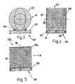
Weitere Vorteile, Merkmale und Einzelheiten der Erfindung ergeben sich aus der nachfolgenden Beschreibung bevorzugter Ausführungsbeispiele sowie anhand der Zeichnung; diese zeigt in:- Fig. 1:
- einen Querschnitt durch einen erfindungsgemäßen Hülsenstrang;
- Fig. 2:
- ein Verfahrensschema, dessen Einzelteile aus Gründen der Übersichtlichkeit nicht in den tatsächlichen Proportionen zueinander skizziert sind;
- Fig. 3:
- eine Frontansicht einer Aufnahmeeinrichtung in Form einer Spule für einen Hülsenstrang;
- Fig. 4 bzw. 5:
- alternative Ausgestaltungen der Spule mit horizontaler bzw. vertikaler Achse.
- - it is possible to achieve a more manageable product which allows the amount of manganese necessary for the treatment of steel to be added with greater precision, while at the same time reducing the potential problems of environmental pollution.
The invention provides a different prior art solution for the addition of manganese alloys in terms of their shape and storage, the nature of their transport from a warehouse to the site and the handling of the latter.
Further advantages, features and details of the invention will become apparent from the following description of preferred embodiments and from the drawing; this shows in:- Fig. 1:
- a cross section through a sleeve strand according to the invention;
- Fig. 2:
- a process scheme whose items are not outlined for the sake of clarity in the actual proportions to each other;
- 3:
- a front view of a receiving device in the form of a coil for a sleeve strand;
- 4 and 5:
- alternative embodiments of the coil with horizontal or vertical axis.
In Fig. 1 ist ein Hülsenstrang 10 runden Querschnittes eines Außendurchmessers d von etwas mehr als 21 mm skizziert, dessen Wandung 12 geringer Dicke f von beispielsweise 0,3 mm bis 1,00 mm aus Stahlblech röhrenartig geformt ist; die beiden Längskanten 16 des Stahlblechstreifens 14 sind unter Bildung eines Falzes 18 gleichgerichtet nebeneinander angeordnet und können gegebenenfalls durch ein Bindemittel, etwa eine Schweißnaht, miteinander verbunden sein. Das eine Querschnittsende des Stahlblechstreifens 14 ist als kurzer Streifen 15 aufgefaltet sowie außenseitig auf den Stahlblechstreifen 14 aufgelegt und innenseitig an den anderen Querschnitts-Endbereich angelegt. Der Hülsenstrang 10 nimmt eine gemahlene Manganlegierung 20 auf, deren Körner eine Korngröße e bis zu 5 mm anbieten.In Fig. 1, a
Bevorzugte Legierungen haben beispielsweise die folgenden Zusammensetzungen:
Die in Fig. 2 skizzierte Anlage enthält eine Aufnahme- und Transporteinrichtung 22 für den aufgespulten Hülsenstrang 10, der unter Bestimmung einer Mittelachse M in dieserals Rolle R aufgewickelt -- lagert sowie durch Paare kleiner Rollen 24 einer Schubeinrichtung oder Injizierstation 26 in Bewegungsrichtung x aus der Spule oder Aufnahmeeinrichtung 22 gezogen wird. Das freie Strangende 11 des Hülsenstranges 10 taucht in den Innenraum 28 einer Gießpfanne 30 ein. Dieser wird in Pfeilrichtung y ein Primärstrahl Q zugeführt, der einem nicht dargestellten Konverter entnommen ist; letzterem sind Roheisen und Schmelzzuschläge aufgegeben worden, um dort mittels Einleitung von Sauerstoff jenen Primärstrahl Q zu erzeugen. In diesem Innenraum 28 schmilzt das freie Strangende 11 des eingetauchten Hülsenstranges 10 in verhältnismäßig großem Abstand i zum Metallspiegel 29, der unterhalb der Oberkante 31 der Gießpfanne 30 verläuft.The plant outlined in Fig. 2 includes a receiving and transporting means 22 for the wound-up
Ein anderes Verfahren zur Herstellung des Primärstrahls Q wird durch den Einsatz von Elektroschmelzöfen realisiert, die drei Elektroden aus Graphitmaterial besitzen, an denen mittels elektrischen Stromes in einem mit feuerfestem Material ausgekleideten Schacht Lichtbogen gegen die Ladung der Rohstoffe erzeugt werden; bei denen handelt es sich im Allgemeinen um Schrott, Eisenschwamm und Schmelzzusätze.Another method of producing the primary jet Q is realized by the use of electric melting furnaces having three electrodes of graphite material at which electric current is generated in a refractory-lined shaft against the charge of the raw materials; These are generally scrap, sponge iron and smelters.
Der Primärstrahl Q wird -- wie gesagt -- der Gießpfanne 30 zugeführt. Während dieses Vorganges erfolgt die Zugabe der genannten Legierungen. Die Schubeinrichtung bzw. Zugabestation 26 drückt das freie Ende des mit der Manganlegierung 20 gefüllten Hülsenstranges 10 mit steuerbarer Geschwindigkeit in die Gießpfanne 30, die zudem den flüssigen Primärstrahl Q aus dem Abstich empfängt bzw. bereits enthält.The primary jet Q is - as I said - the
Diese Anordnung hat den Vorteil, dass sich die aktive Länge des Hülsenstranges 10 über vom Bedienpersonal gesteuerte Systeme dosieren lässt. Letzteres bestimmt -- sobald man die chemische Analyse des zu behandelnden Primärstrahls Q kennt -- durch Berechnung die Menge der Manganlegierung 20, die zugegeben werden muss, dies ausgedrückt in der Meterzahl des in die Gießpfanne 30 geführten Hülsenstranges 10. In einigen Fällen ist das System programmgesteuert und führt jene Berechnung automatisch durch.This arrangement has the advantage that the active length of the
Wie die Fig. 3 und 4 verdeutlichen, besteht die Aufnahmeeinrichtung 22 hier aus einem -- Metall- oder Holzprofile 32 enthaltenden -- Bodengestell 34 und einem davon aufragenden Stützgerüst 36 mit vom Bodengestell 34 beidseits der -- auf Längsprofilen 35 ruhenden -- Rolle R aufragenden Halteprofilen 37, die in Fig. 2, 4 durch Querprofile 38 für die Rolle R des Hülsenstranges 10 verbunden sind. In den Fig. 2, 4 verläuft die Mittelachse M jener Rolle R horizontal, in der Aufnahmeeinrichtung 22a der Fig. 5 hingegen vertikal; hier fehlen am Stützgerüst 36a in dieser Anwendung nicht erforderliche Querprofile.As shown in FIGS. 3 and 4 illustrate, the receiving
Bei der geschilderten Vorgehensweise werden also in den Primärstrahl Q während des Abstichs in die Gießpfanne 30 die Manganlegierung 20 und übrige Komponenten mittels des Hülsenstranges 10 als röhrenförmiges Behältnis zugeführt. Letzteres ist aus einem Werkstoff gefertigt, der aufgrund der ihm innewohnenden Eigenschaften eine bestimmte Widerstandsfähigkeit gegen hohe Temperaturen besitzt. Der auch als Einhülsung bezeichnete Hülsenstrang 10 wird auf Spezialmaschinen hergestellt und dann -- wie gesagt -- als Rolle R zum Einsatzort gebracht. Als Ausgangswerkstoff wird Bandstahl verwendet, dem in mehreren aufeinanderfolgenden Schritten formgerechter Biegung eine U-Form verliehen wird. Zu diesem Zeitpunkt wird mit Hilfe eines automatisierten Beschickungssystems die gemahlene Manganlegierung 20 der Einhülsung 10 zugeführt und zwar präzise bemessen in Bezug auf das Gewicht der nunmehr enthaltenen Legierung, ausgedrückt in Gramm je Meter.In the described procedure, the
In nachfolgenden Schritten der formgerechten Biegung wird -- wie erörtert -- die Stahlblechröhre aus dem Stahlblechstreifen 14 geschlossen. Das sich ergebende röhrenförmige Produkt wird in oben beschriebener Weise ähnlich einem Kabel aufgerollt. Die dabei entstehende und befüllte Spule oder Wickelrolle R lagert dann in der Aufnahmeeinrichtung 22, die zwischen 1.000 Meter und 5.000 Meter des Hülsenstranges 10 aufnehmen kann und sich mit fahrbaren Hebezeugen für Lasten von mindestens 2,5 Tonnen auf einfache Weise transportieren lässt. Die Lagerung hat in überdachten Räumen zu erfolgen.In subsequent steps of conforming bending, as discussed, the steel sheet tube is closed from
Es wird so eine präzisere und rationellere Zugabe der Menge von Manganlegierung 20 als üblich erzielt, da die Meter für Meter gewährleistete Gewichtshomogenität der enthaltenen körnigen Manganlegierung 20 eine bessere Messung ermöglicht.There is thus achieved a more precise and rational addition of the amount of
Die Tatsache, dass die Einhülsung 10 dank ihrer röhrenförmigen Ummantelung aus dem Stahlblechstreifen 14 für kurze Zeit den im Inneren der Gießpfanne 30 herrschenden Temperaturen widersteht, ohne sich aufzulösen, gestattet es, in die tieferen Zonen der Gießpfanne 30 einzudringen. Auf diese Art und Weise erfolgt die Zugabe im Innersten der flüssigen Stahlmenge, was es mit sich bringt, dass das Material im Stahlbad effizienter genutzt wird und Oberflächenreaktionen vermieden werden.The fact that the
Claims (14)
dadurch gekennzeichnet,
dass der glühenden Masse eines Primärstahles (Q) während dessen Abstiches in eine Gießpfanne (30) die Manganlegierungen' (20) in Form von Ferromangan mit hohem, mittlerem und niedrigem Kohlenstoffanteil, Mangansilizium mit normalem und niedrigem Kohlenstoffgehalt zugegeben werden.Method for supplying at least one manganese alloy to a steel material in steelmaking,
characterized,
that a primary steel (Q) during which tapping into a ladle (30), the manganese alloys' (20) are added in the form of ferro-manganese with high, medium and low carbon content, manganese silicon with normal or low carbon content of glowing mass.
Applications Claiming Priority (1)
| Application Number | Priority Date | Filing Date | Title |
|---|---|---|---|
| ARP050100832 | 2005-03-04 |
Publications (2)
| Publication Number | Publication Date |
|---|---|
| EP1698705A2 true EP1698705A2 (en) | 2006-09-06 |
| EP1698705A3 EP1698705A3 (en) | 2007-04-11 |
Family
ID=36944291
Family Applications (1)
| Application Number | Title | Priority Date | Filing Date |
|---|---|---|---|
| EP06003578A Withdrawn EP1698705A3 (en) | 2005-03-04 | 2006-02-22 | Process and installation for the addition of a manganese alloy during steel processing |
Country Status (2)
| Country | Link |
|---|---|
| US (1) | US20060198756A1 (en) |
| EP (1) | EP1698705A3 (en) |
Cited By (1)
| Publication number | Priority date | Publication date | Assignee | Title |
|---|---|---|---|---|
| WO2022117315A1 (en) * | 2020-12-03 | 2022-06-09 | Compagnia Commerciale Srl | Method for melting ferrous metals, non-ferrous metals, machining waste and scrap and steel |
Families Citing this family (2)
| Publication number | Priority date | Publication date | Assignee | Title |
|---|---|---|---|---|
| US8224136B2 (en) * | 2010-04-01 | 2012-07-17 | Furukawa Electric Co., Ltd. | Optical multiplexer/demultiplexer module and prism using for the same |
| US20210340639A1 (en) * | 2020-04-30 | 2021-11-04 | Deere & Company | Nickel magnesium wire injection system and method thereof |
Family Cites Families (7)
| Publication number | Priority date | Publication date | Assignee | Title |
|---|---|---|---|---|
| US3741753A (en) * | 1971-07-26 | 1973-06-26 | Timken Co | Method for adding manganese alloying member to steel |
| JPS5638295B2 (en) * | 1974-05-01 | 1981-09-05 | ||
| DE2632707C3 (en) * | 1976-07-21 | 1983-04-07 | Ernst Dipl.-Ing. 4006 Erkrath Beiersdorf | Charging system on electric arc furnaces for adding alloying agents and aggregates |
| DE3107016C2 (en) * | 1981-02-25 | 1983-09-08 | M.A.N. Maschinenfabrik Augsburg-Nürnberg AG, 4200 Oberhausen | Arc furnace system for melting iron carriers |
| IT1218464B (en) * | 1985-01-17 | 1990-04-19 | Kinglor Ltd | PROCEDURE FOR THE AUTOMATIC FORMING OF A CONTINUOUS METALLIC TUBE FILLED WITH FERROLEGHE AND OTHER POWDERED MATERIALS (ANIMATED WIRE) AND ITS DIRECT INTRODUCTION INTO THE LIQUID METAL OF A LADDER, AND RELATIVE FORMING EQUIPMENT |
| US6346135B1 (en) * | 1998-12-10 | 2002-02-12 | Minerals Technologies Inc. | Cored wire for treating molten metal |
| DE19916234C2 (en) * | 1999-03-01 | 2001-03-08 | Odermath Stahlwerkstechnik | Cored wire for the treatment of melts by wire injection |
-
2006
- 2006-02-22 EP EP06003578A patent/EP1698705A3/en not_active Withdrawn
- 2006-03-03 US US11/367,090 patent/US20060198756A1/en not_active Abandoned
Cited By (1)
| Publication number | Priority date | Publication date | Assignee | Title |
|---|---|---|---|---|
| WO2022117315A1 (en) * | 2020-12-03 | 2022-06-09 | Compagnia Commerciale Srl | Method for melting ferrous metals, non-ferrous metals, machining waste and scrap and steel |
Also Published As
| Publication number | Publication date |
|---|---|
| EP1698705A3 (en) | 2007-04-11 |
| US20060198756A1 (en) | 2006-09-07 |
Similar Documents
| Publication | Publication Date | Title |
|---|---|---|
| DE60110539T2 (en) | Ferritic stainless steel sheet suitable for a fuel tank and a fuel pipe, and a method of manufacturing the same | |
| EP2688691B2 (en) | Apparatus and method for sampling thick strips | |
| DE102005023133B4 (en) | Plant for measuring and controlling the feeding of a furnace with molten metal and scrap and corresponding process | |
| DE69325644T2 (en) | High-strength hot-rolled steel sheet with excellent uniform elongation after cold working and process for its production | |
| EP2557184A1 (en) | Hot-rolled profiled steel reinforcement for reinforced concrete with improved fire resistance and method for producing same | |
| DE102014226384A1 (en) | Charging system and charging process for forging machines | |
| DE112013001401T5 (en) | BAND OF AMORPHER ALLOY | |
| EP3019292B1 (en) | Method for producing a flat product from an iron-based shape memory alloy | |
| DE2522754C3 (en) | Fusible electrode | |
| DE2513763C3 (en) | Process for producing a roller with one or more circumferential grooves | |
| DE4497994C2 (en) | Cold rolled steel sheet and process for its manufacture | |
| WO2006094718A1 (en) | Process and installation for producing a lightweight structural steel with a high manganese content | |
| EP1631691A2 (en) | Method and installation for the production of steel products having an optimum surface quality | |
| EP1698705A2 (en) | Process and installation for the addition of a manganese alloy during steel processing | |
| DE2061122B2 (en) | Process for the controlled decarburization of metal, especially steel melts under reduced pressure in closed vessels | |
| DE102009007470B4 (en) | Cored wire for MSG welding of FeMn steel | |
| DE2900497A1 (en) | METHOD AND DEVICE FOR TRANSPORTING WARM METAL MATERIAL | |
| EP0764063B1 (en) | Method of producing a seamless hot-finished tube | |
| DE1508298A1 (en) | Steel mill | |
| EP3771746A1 (en) | Steel, steel sheet product, method for producing steel sheet product and use thereof | |
| DE19520833A1 (en) | Process for the production of a seamless hot-worked pipe | |
| EP1192401B1 (en) | Method and system for the treatment of liquid metals | |
| DE2519275A1 (en) | METHOD FOR CONTINUOUS STEEL CASTING | |
| DE7611861U1 (en) | COMPOSITE THREAD BASED ON CER AND OTHER RARE EARTH | |
| DE1917449A1 (en) | Device for the production of steel pipes by extrusion |
Legal Events
| Date | Code | Title | Description |
|---|---|---|---|
| PUAI | Public reference made under article 153(3) epc to a published international application that has entered the european phase |
Free format text: ORIGINAL CODE: 0009012 |
|
| AK | Designated contracting states |
Kind code of ref document: A2 Designated state(s): AT BE BG CH CY CZ DE DK EE ES FI FR GB GR HU IE IS IT LI LT LU LV MC NL PL PT RO SE SI SK TR |
|
| AX | Request for extension of the european patent |
Extension state: AL BA HR MK YU |
|
| PUAL | Search report despatched |
Free format text: ORIGINAL CODE: 0009013 |
|
| AK | Designated contracting states |
Kind code of ref document: A3 Designated state(s): AT BE BG CH CY CZ DE DK EE ES FI FR GB GR HU IE IS IT LI LT LU LV MC NL PL PT RO SE SI SK TR |
|
| AX | Request for extension of the european patent |
Extension state: AL BA HR MK YU |
|
| AKX | Designation fees paid | ||
| STAA | Information on the status of an ep patent application or granted ep patent |
Free format text: STATUS: THE APPLICATION IS DEEMED TO BE WITHDRAWN |
|
| 18D | Application deemed to be withdrawn |
Effective date: 20071012 |
|
| REG | Reference to a national code |
Ref country code: DE Ref legal event code: 8566 |