EP1697642B1 - Fasteners and other assemblies - Google Patents
Fasteners and other assemblies Download PDFInfo
- Publication number
- EP1697642B1 EP1697642B1 EP04797029.8A EP04797029A EP1697642B1 EP 1697642 B1 EP1697642 B1 EP 1697642B1 EP 04797029 A EP04797029 A EP 04797029A EP 1697642 B1 EP1697642 B1 EP 1697642B1
- Authority
- EP
- European Patent Office
- Prior art keywords
- fastener
- engagement means
- microprocessor
- shape memory
- memory alloy
- Prior art date
- Legal status (The legal status is an assumption and is not a legal conclusion. Google has not performed a legal analysis and makes no representation as to the accuracy of the status listed.)
- Expired - Lifetime
Links
Images



Classifications
-
- F—MECHANICAL ENGINEERING; LIGHTING; HEATING; WEAPONS; BLASTING
- F16—ENGINEERING ELEMENTS AND UNITS; GENERAL MEASURES FOR PRODUCING AND MAINTAINING EFFECTIVE FUNCTIONING OF MACHINES OR INSTALLATIONS; THERMAL INSULATION IN GENERAL
- F16B—DEVICES FOR FASTENING OR SECURING CONSTRUCTIONAL ELEMENTS OR MACHINE PARTS TOGETHER, e.g. NAILS, BOLTS, CIRCLIPS, CLAMPS, CLIPS OR WEDGES; JOINTS OR JOINTING
- F16B21/00—Means for preventing relative axial movement of a pin, spigot, shaft or the like and a member surrounding it; Stud-and-socket releasable fastenings
- F16B21/10—Means for preventing relative axial movement of a pin, spigot, shaft or the like and a member surrounding it; Stud-and-socket releasable fastenings by separate parts
- F16B21/16—Means for preventing relative axial movement of a pin, spigot, shaft or the like and a member surrounding it; Stud-and-socket releasable fastenings by separate parts with grooves or notches in the pin or shaft
-
- B—PERFORMING OPERATIONS; TRANSPORTING
- B62—LAND VEHICLES FOR TRAVELLING OTHERWISE THAN ON RAILS
- B62D—MOTOR VEHICLES; TRAILERS
- B62D27/00—Connections between superstructure or understructure sub-units
-
- B—PERFORMING OPERATIONS; TRANSPORTING
- B62—LAND VEHICLES FOR TRAVELLING OTHERWISE THAN ON RAILS
- B62D—MOTOR VEHICLES; TRAILERS
- B62D65/00—Designing, manufacturing, e.g. assembling, facilitating disassembly, or structurally modifying motor vehicles or trailers, not otherwise provided for
- B62D65/02—Joining sub-units or components to, or positioning sub-units or components with respect to, body shell or other sub-units or components
-
- B—PERFORMING OPERATIONS; TRANSPORTING
- B62—LAND VEHICLES FOR TRAVELLING OTHERWISE THAN ON RAILS
- B62J—CYCLE SADDLES OR SEATS; AUXILIARY DEVICES OR ACCESSORIES SPECIALLY ADAPTED TO CYCLES AND NOT OTHERWISE PROVIDED FOR, e.g. ARTICLE CARRIERS OR CYCLE PROTECTORS
- B62J17/00—Weather guards for riders; Fairings or stream-lining parts not otherwise provided for
- B62J17/02—Weather guards for riders; Fairings or stream-lining parts not otherwise provided for shielding only the rider's front
- B62J17/04—Windscreens
-
- B—PERFORMING OPERATIONS; TRANSPORTING
- B62—LAND VEHICLES FOR TRAVELLING OTHERWISE THAN ON RAILS
- B62J—CYCLE SADDLES OR SEATS; AUXILIARY DEVICES OR ACCESSORIES SPECIALLY ADAPTED TO CYCLES AND NOT OTHERWISE PROVIDED FOR, e.g. ARTICLE CARRIERS OR CYCLE PROTECTORS
- B62J50/00—Arrangements specially adapted for use on cycles not provided for in main groups B62J1/00 - B62J45/00
- B62J50/20—Information-providing devices
- B62J50/21—Information-providing devices intended to provide information to rider or passenger
- B62J50/225—Mounting arrangements therefor
-
- E—FIXED CONSTRUCTIONS
- E05—LOCKS; KEYS; WINDOW OR DOOR FITTINGS; SAFES
- E05B—LOCKS; ACCESSORIES THEREFOR; HANDCUFFS
- E05B47/00—Operating or controlling locks or other fastening devices by electric or magnetic means
- E05B47/0001—Operating or controlling locks or other fastening devices by electric or magnetic means with electric actuators; Constructional features thereof
- E05B47/0009—Operating or controlling locks or other fastening devices by electric or magnetic means with electric actuators; Constructional features thereof with thermo-electric actuators, e.g. heated bimetals
-
- E—FIXED CONSTRUCTIONS
- E05—LOCKS; KEYS; WINDOW OR DOOR FITTINGS; SAFES
- E05B—LOCKS; ACCESSORIES THEREFOR; HANDCUFFS
- E05B47/00—Operating or controlling locks or other fastening devices by electric or magnetic means
- E05B47/06—Controlling mechanically-operated bolts by electro-magnetically-operated detents
-
- E—FIXED CONSTRUCTIONS
- E05—LOCKS; KEYS; WINDOW OR DOOR FITTINGS; SAFES
- E05B—LOCKS; ACCESSORIES THEREFOR; HANDCUFFS
- E05B81/00—Power-actuated vehicle locks
- E05B81/02—Power-actuated vehicle locks characterised by the type of actuators used
- E05B81/04—Electrical
-
- E—FIXED CONSTRUCTIONS
- E05—LOCKS; KEYS; WINDOW OR DOOR FITTINGS; SAFES
- E05B—LOCKS; ACCESSORIES THEREFOR; HANDCUFFS
- E05B83/00—Vehicle locks specially adapted for particular types of wing or vehicle
- E05B83/28—Locks for glove compartments, console boxes, fuel inlet covers or the like
- E05B83/34—Locks for glove compartments, console boxes, fuel inlet covers or the like for fuel inlet covers essentially flush with the vehicle surface
-
- F—MECHANICAL ENGINEERING; LIGHTING; HEATING; WEAPONS; BLASTING
- F16—ENGINEERING ELEMENTS AND UNITS; GENERAL MEASURES FOR PRODUCING AND MAINTAINING EFFECTIVE FUNCTIONING OF MACHINES OR INSTALLATIONS; THERMAL INSULATION IN GENERAL
- F16B—DEVICES FOR FASTENING OR SECURING CONSTRUCTIONAL ELEMENTS OR MACHINE PARTS TOGETHER, e.g. NAILS, BOLTS, CIRCLIPS, CLAMPS, CLIPS OR WEDGES; JOINTS OR JOINTING
- F16B21/00—Means for preventing relative axial movement of a pin, spigot, shaft or the like and a member surrounding it; Stud-and-socket releasable fastenings
- F16B21/06—Releasable fastening devices with snap-action
-
- F—MECHANICAL ENGINEERING; LIGHTING; HEATING; WEAPONS; BLASTING
- F16—ENGINEERING ELEMENTS AND UNITS; GENERAL MEASURES FOR PRODUCING AND MAINTAINING EFFECTIVE FUNCTIONING OF MACHINES OR INSTALLATIONS; THERMAL INSULATION IN GENERAL
- F16B—DEVICES FOR FASTENING OR SECURING CONSTRUCTIONAL ELEMENTS OR MACHINE PARTS TOGETHER, e.g. NAILS, BOLTS, CIRCLIPS, CLAMPS, CLIPS OR WEDGES; JOINTS OR JOINTING
- F16B21/00—Means for preventing relative axial movement of a pin, spigot, shaft or the like and a member surrounding it; Stud-and-socket releasable fastenings
- F16B21/06—Releasable fastening devices with snap-action
- F16B21/08—Releasable fastening devices with snap-action in which the stud, pin, or spigot has a resilient part
- F16B21/086—Releasable fastening devices with snap-action in which the stud, pin, or spigot has a resilient part the shank of the stud, pin or spigot having elevations, ribs, fins or prongs intended for deformation or tilting predominantly in a direction perpendicular to the direction of insertion
-
- F—MECHANICAL ENGINEERING; LIGHTING; HEATING; WEAPONS; BLASTING
- F16—ENGINEERING ELEMENTS AND UNITS; GENERAL MEASURES FOR PRODUCING AND MAINTAINING EFFECTIVE FUNCTIONING OF MACHINES OR INSTALLATIONS; THERMAL INSULATION IN GENERAL
- F16B—DEVICES FOR FASTENING OR SECURING CONSTRUCTIONAL ELEMENTS OR MACHINE PARTS TOGETHER, e.g. NAILS, BOLTS, CIRCLIPS, CLAMPS, CLIPS OR WEDGES; JOINTS OR JOINTING
- F16B21/00—Means for preventing relative axial movement of a pin, spigot, shaft or the like and a member surrounding it; Stud-and-socket releasable fastenings
- F16B21/10—Means for preventing relative axial movement of a pin, spigot, shaft or the like and a member surrounding it; Stud-and-socket releasable fastenings by separate parts
- F16B21/16—Means for preventing relative axial movement of a pin, spigot, shaft or the like and a member surrounding it; Stud-and-socket releasable fastenings by separate parts with grooves or notches in the pin or shaft
- F16B21/18—Means for preventing relative axial movement of a pin, spigot, shaft or the like and a member surrounding it; Stud-and-socket releasable fastenings by separate parts with grooves or notches in the pin or shaft with circlips or like resilient retaining devices, i.e. resilient in the plane of the ring or the like; Details
- F16B21/183—Means for preventing relative axial movement of a pin, spigot, shaft or the like and a member surrounding it; Stud-and-socket releasable fastenings by separate parts with grooves or notches in the pin or shaft with circlips or like resilient retaining devices, i.e. resilient in the plane of the ring or the like; Details internal, i.e. with spreading action
-
- F—MECHANICAL ENGINEERING; LIGHTING; HEATING; WEAPONS; BLASTING
- F16—ENGINEERING ELEMENTS AND UNITS; GENERAL MEASURES FOR PRODUCING AND MAINTAINING EFFECTIVE FUNCTIONING OF MACHINES OR INSTALLATIONS; THERMAL INSULATION IN GENERAL
- F16B—DEVICES FOR FASTENING OR SECURING CONSTRUCTIONAL ELEMENTS OR MACHINE PARTS TOGETHER, e.g. NAILS, BOLTS, CIRCLIPS, CLAMPS, CLIPS OR WEDGES; JOINTS OR JOINTING
- F16B21/00—Means for preventing relative axial movement of a pin, spigot, shaft or the like and a member surrounding it; Stud-and-socket releasable fastenings
- F16B21/10—Means for preventing relative axial movement of a pin, spigot, shaft or the like and a member surrounding it; Stud-and-socket releasable fastenings by separate parts
- F16B21/16—Means for preventing relative axial movement of a pin, spigot, shaft or the like and a member surrounding it; Stud-and-socket releasable fastenings by separate parts with grooves or notches in the pin or shaft
- F16B21/18—Means for preventing relative axial movement of a pin, spigot, shaft or the like and a member surrounding it; Stud-and-socket releasable fastenings by separate parts with grooves or notches in the pin or shaft with circlips or like resilient retaining devices, i.e. resilient in the plane of the ring or the like; Details
- F16B21/186—Means for preventing relative axial movement of a pin, spigot, shaft or the like and a member surrounding it; Stud-and-socket releasable fastenings by separate parts with grooves or notches in the pin or shaft with circlips or like resilient retaining devices, i.e. resilient in the plane of the ring or the like; Details external, i.e. with contracting action
-
- B—PERFORMING OPERATIONS; TRANSPORTING
- B60—VEHICLES IN GENERAL
- B60K—ARRANGEMENT OR MOUNTING OF PROPULSION UNITS OR OF TRANSMISSIONS IN VEHICLES; ARRANGEMENT OR MOUNTING OF PLURAL DIVERSE PRIME-MOVERS IN VEHICLES; AUXILIARY DRIVES FOR VEHICLES; INSTRUMENTATION OR DASHBOARDS FOR VEHICLES; ARRANGEMENTS IN CONNECTION WITH COOLING, AIR INTAKE, GAS EXHAUST OR FUEL SUPPLY OF PROPULSION UNITS IN VEHICLES
- B60K15/00—Arrangement in connection with fuel supply of combustion engines or other fuel consuming energy converters, e.g. fuel cells; Mounting or construction of fuel tanks
- B60K15/03—Fuel tanks
- B60K15/04—Tank inlets
- B60K15/05—Inlet covers
- B60K2015/0515—Arrangements for closing or opening of inlet cover
- B60K2015/053—Arrangements for closing or opening of inlet cover with hinged connection to the vehicle body
-
- B—PERFORMING OPERATIONS; TRANSPORTING
- B60—VEHICLES IN GENERAL
- B60K—ARRANGEMENT OR MOUNTING OF PROPULSION UNITS OR OF TRANSMISSIONS IN VEHICLES; ARRANGEMENT OR MOUNTING OF PLURAL DIVERSE PRIME-MOVERS IN VEHICLES; AUXILIARY DRIVES FOR VEHICLES; INSTRUMENTATION OR DASHBOARDS FOR VEHICLES; ARRANGEMENTS IN CONNECTION WITH COOLING, AIR INTAKE, GAS EXHAUST OR FUEL SUPPLY OF PROPULSION UNITS IN VEHICLES
- B60K15/00—Arrangement in connection with fuel supply of combustion engines or other fuel consuming energy converters, e.g. fuel cells; Mounting or construction of fuel tanks
- B60K15/03—Fuel tanks
- B60K15/04—Tank inlets
- B60K15/05—Inlet covers
- B60K2015/0561—Locking means for the inlet cover
-
- B—PERFORMING OPERATIONS; TRANSPORTING
- B62—LAND VEHICLES FOR TRAVELLING OTHERWISE THAN ON RAILS
- B62J—CYCLE SADDLES OR SEATS; AUXILIARY DEVICES OR ACCESSORIES SPECIALLY ADAPTED TO CYCLES AND NOT OTHERWISE PROVIDED FOR, e.g. ARTICLE CARRIERS OR CYCLE PROTECTORS
- B62J1/00—Saddles or other seats for cycles; Arrangement thereof; Component parts
- B62J1/08—Frames for saddles; Connections between saddle frames and seat pillars; Seat pillars
-
- B—PERFORMING OPERATIONS; TRANSPORTING
- B62—LAND VEHICLES FOR TRAVELLING OTHERWISE THAN ON RAILS
- B62J—CYCLE SADDLES OR SEATS; AUXILIARY DEVICES OR ACCESSORIES SPECIALLY ADAPTED TO CYCLES AND NOT OTHERWISE PROVIDED FOR, e.g. ARTICLE CARRIERS OR CYCLE PROTECTORS
- B62J9/00—Containers specially adapted for cycles, e.g. panniers or saddle bags
- B62J9/20—Containers specially adapted for cycles, e.g. panniers or saddle bags attached to the cycle as accessories
- B62J9/26—Containers specially adapted for cycles, e.g. panniers or saddle bags attached to the cycle as accessories to the saddle, e.g. saddle bags
-
- E—FIXED CONSTRUCTIONS
- E05—LOCKS; KEYS; WINDOW OR DOOR FITTINGS; SAFES
- E05B—LOCKS; ACCESSORIES THEREFOR; HANDCUFFS
- E05B63/00—Locks or fastenings with special structural characteristics
- E05B2063/0026—Elongated, e.g. stud-like, striker entering into an opening in which movable detent means engage the elongated striker
-
- F—MECHANICAL ENGINEERING; LIGHTING; HEATING; WEAPONS; BLASTING
- F16—ENGINEERING ELEMENTS AND UNITS; GENERAL MEASURES FOR PRODUCING AND MAINTAINING EFFECTIVE FUNCTIONING OF MACHINES OR INSTALLATIONS; THERMAL INSULATION IN GENERAL
- F16B—DEVICES FOR FASTENING OR SECURING CONSTRUCTIONAL ELEMENTS OR MACHINE PARTS TOGETHER, e.g. NAILS, BOLTS, CIRCLIPS, CLAMPS, CLIPS OR WEDGES; JOINTS OR JOINTING
- F16B2200/00—Constructional details of connections not covered for in other groups of this subclass
- F16B2200/77—Use of a shape-memory material
-
- Y—GENERAL TAGGING OF NEW TECHNOLOGICAL DEVELOPMENTS; GENERAL TAGGING OF CROSS-SECTIONAL TECHNOLOGIES SPANNING OVER SEVERAL SECTIONS OF THE IPC; TECHNICAL SUBJECTS COVERED BY FORMER USPC CROSS-REFERENCE ART COLLECTIONS [XRACs] AND DIGESTS
- Y10—TECHNICAL SUBJECTS COVERED BY FORMER USPC
- Y10T—TECHNICAL SUBJECTS COVERED BY FORMER US CLASSIFICATION
- Y10T24/00—Buckles, buttons, clasps, etc.
- Y10T24/45—Separable-fastener or required component thereof [e.g., projection and cavity to complete interlock]
- Y10T24/45225—Separable-fastener or required component thereof [e.g., projection and cavity to complete interlock] including member having distinct formations and mating member selectively interlocking therewith
- Y10T24/45461—Interlocking portion actuated or released responsive to preselected condition [e.g., heat, pressure]
-
- Y—GENERAL TAGGING OF NEW TECHNOLOGICAL DEVELOPMENTS; GENERAL TAGGING OF CROSS-SECTIONAL TECHNOLOGIES SPANNING OVER SEVERAL SECTIONS OF THE IPC; TECHNICAL SUBJECTS COVERED BY FORMER USPC CROSS-REFERENCE ART COLLECTIONS [XRACs] AND DIGESTS
- Y10—TECHNICAL SUBJECTS COVERED BY FORMER USPC
- Y10T—TECHNICAL SUBJECTS COVERED BY FORMER US CLASSIFICATION
- Y10T24/00—Buckles, buttons, clasps, etc.
- Y10T24/45—Separable-fastener or required component thereof [e.g., projection and cavity to complete interlock]
- Y10T24/45225—Separable-fastener or required component thereof [e.g., projection and cavity to complete interlock] including member having distinct formations and mating member selectively interlocking therewith
- Y10T24/45466—Separable-fastener or required component thereof [e.g., projection and cavity to complete interlock] including member having distinct formations and mating member selectively interlocking therewith having electric or fluid powered, actuation or release, of interlock
-
- Y—GENERAL TAGGING OF NEW TECHNOLOGICAL DEVELOPMENTS; GENERAL TAGGING OF CROSS-SECTIONAL TECHNOLOGIES SPANNING OVER SEVERAL SECTIONS OF THE IPC; TECHNICAL SUBJECTS COVERED BY FORMER USPC CROSS-REFERENCE ART COLLECTIONS [XRACs] AND DIGESTS
- Y10—TECHNICAL SUBJECTS COVERED BY FORMER USPC
- Y10T—TECHNICAL SUBJECTS COVERED BY FORMER US CLASSIFICATION
- Y10T24/00—Buckles, buttons, clasps, etc.
- Y10T24/45—Separable-fastener or required component thereof [e.g., projection and cavity to complete interlock]
- Y10T24/45225—Separable-fastener or required component thereof [e.g., projection and cavity to complete interlock] including member having distinct formations and mating member selectively interlocking therewith
- Y10T24/45471—Projection having movable connection between components thereof or variable configuration
-
- Y—GENERAL TAGGING OF NEW TECHNOLOGICAL DEVELOPMENTS; GENERAL TAGGING OF CROSS-SECTIONAL TECHNOLOGIES SPANNING OVER SEVERAL SECTIONS OF THE IPC; TECHNICAL SUBJECTS COVERED BY FORMER USPC CROSS-REFERENCE ART COLLECTIONS [XRACs] AND DIGESTS
- Y10—TECHNICAL SUBJECTS COVERED BY FORMER USPC
- Y10T—TECHNICAL SUBJECTS COVERED BY FORMER US CLASSIFICATION
- Y10T70/00—Locks
- Y10T70/70—Operating mechanism
- Y10T70/7051—Using a powered device [e.g., motor]
- Y10T70/7062—Electrical type [e.g., solenoid]
Definitions
- This invention is concerned with fasteners and other assemblies.
- the invention covers a wide range of fasteners, fastening systems, fastener assemblies and related areas. These represent improvements over prior art fasteners and fastener assemblies, etc.
- the material adapted to contract when activated is preferably shape memory alloy wire.
- Shape memory alloys are known and are usually made predominantly or wholly of titanium and nickel. They may also include other material, such as aluminium, zinc and copper.
- a shape memory alloy is capable of adopting one shape below a predetermined transition temperature and changing to a second shape once its temperature exceeds the transition temperature. Conversely, when the shape memory alloy cools below the transition temperature, it is capable of adopting the first shape again. In connection with the present invention, the shape memory alloy contracts when heated in situ.
- Shape memory alloy wire currently available, such as that sold under the trade mark Nitinol is capable of contracting by about 3% when activated by heating.
- Activation of the material adapted to contract when activated is preferably achieved through electrical resistance heating, with a wire feed to the assembly.
- Activation of the shape memory alloy wire can be initiated from a central location, using the wiring system of, for example, an air craft or automobile. It is also within the scope of this invention that the activation is initiated by remote means, such as a hand held tool operating through the use of any suitable form of energy, including microwave, electric magnetic, sonic, infra-red, radio frequency and so on.
- activation of the shape memory alloy may take place through heating, other means of activation may be suitable and are within the scope of this invention.
- fasteners and fastening systems of the invention may be particularly suitable for use in connection with automobiles and to some extent the description below may focus on this application. However, it is to be understood that the scope of the invention is not limited to this application.
- CAN Controller Area Network
- LIN local interconnect network
- the present invention in some of its aspects is intended to take advantage of the trend towards increased electronic control in vehicles.
- the present invention provides versions of fasteners which may be suitable for use in vehicles and which may provide significant advantages in relation to assembly of vehicles and service of vehicles.
- the fasteners of the present invention may be suitable for connection to a vehicle computer via a CAN or LIN.
- fasteners and fastening systems of the invention can be designed to be activated only by authorised parties, such as those engaged in vehicle assembly or servicing. Others can be designed to be operated by vehicle owners.
- any of the fasteners and the fastening systems of the invention can have primary and secondary functions, the primary function being to attach components to the vehicle body and the secondary function being the control of component switching. It is possible that use of fastening systems according to the invention may reduce the number of sub-network wiring components required in a vehicle, through direct connection into the CAN bus, for example. In effect, each fastener may become its own multiplex module/communications gateway or node on the CAN bus.
- This invention provides a fastener which represents a variation of a fastener disclosed in International Patent Application No. PCT/AU03/00759 ("the original beam fastener").
- the original beam fastener had a flexible beam which was movable between an engagement position and a disengagement position when actuating means were activated.
- the actuating means included a material adapted to contract when activated, such as a shape memory alloy. In the fastener of this invention, it is no longer necessary that the beam is flexible.
- this invention provides a fastener according to Claim 1.
- the fastener of the invention is designed so that, when the shape memory alloy contracts, the fastening element flexes or moves about the flex point and the engagement means is drawn out of the engagement position.
- the fastener may be otherwise as disclosed in International Patent Application No. PCT/AU03/00759 , except that it is not necessary that the beam flexes to enable the engagement means to disengage.
- the fastener of the invention may be made of any suitable material, including plastic or metal.
- the fastener may be made of a combination of materials.
- the tensile strength of the beam should be sufficiently high that the fastener can fasten useful loads.
- the material of the beam has sufficient fatigue strength to accommodate the desired number of locked/unlocked cycles.
- the engagement means preferably takes the form of a projecting wedge which can key into a corresponding recess in a wall of an element.
- the engagement means may be a snap means, a rod for latching over a hook, or an aperture which can latch over a projection such as a peg.
- the engagement means may take the form of a dovetail on the beam fitting into an appropriate recess.
- the fastener of the invention can engage with an identical fastener, for example.
- the shape memory alloy wire takes the form of a titanium-nickel wire which, when sufficient energy in the form of an electrical current is applied, heats to or above a temperature at which the material shrinks by about 4 to 5%.
- the beam can be caused to move away from the engagement position in which a first element is fastened to a second element, thereby releasing the elements.
- the shape memory material is permitted to cool below the transitional temperature, in some embodiments the beam may assume the engagement position and the elements may be fastened again.
- the flex point is preferably located forward of the engagement means so as to improve force geometry and to increase the retaining strength of the fastener. An example of this is illustrated in the attached drawings.
- the shape memory alloy wire which contracts when activated is contained in one or more grooves in the beam. This can provide physical protection for the material as well as decreasing heat up/cool down times. It can also reduce ambient temperature effects and increase beam strength. It can enable the beam to maintained in the disengagement position for a desired length of time. This can be regarded as a "hold" state. Such a hold state may be established using less power (such as electrical current) than that required to move the beam from the engagement position to the disengagement position. This may be achieved by insulating the shape memory alloy wire which contracts when activated by being maintained in grooves in the beam.
- bias means urging the fastener to the engagement position.
- a non-limiting example of such bias means is a leaf spring, preferably of metal. This can urge the material to stretch out once it has cooled and relaxed. It can also greatly reduce any potential for creep deformation in the fastening element when made of plastic.
- the beam does not need to bend, it may be made thicker and can have more strength.
- the beam may be machined, cast, moulded or formed in any desirable way.
- Means intended for engagement by the engagement means may take any suitable form. Some have already been mentioned above, for example part of a snap means, a hook, a peg, a recess or an identical fastener. If the fastener is used for fastening a fuel filler door to a car body, for example, it is preferred that means for engagement by the engagement means is an aperture on the door.
- the actuating means is preferably actuated either through a suitable switch located on the dash board of the vehicle or through a signal generated from the vehicle key.
- a suitable switch located on the dash board of the vehicle or through a signal generated from the vehicle key.
- the fastener of the invention may be "intelligent" or not. It may be addressable. It may be part of a network. It may have a switching capacity and it may include sensors. All of these and other information is contained in international patent application No. PCT/AU03/00759 . All applicable features in PCT/AU03/00759 apply to the fastener of the present invention.
- the fastener includes a microprocessor which can carry out one or more roles.
- Microprocessor can control the energy delivery to the shape memory alloy wire, preferably by a temperature-dependent algorithm. It can control temperature of the shape memory alloy wire. It can sense the state of the fastener and whether it is engaged or not. It can report this, along with secondary sensed information, to a network of which the fastener forms a part.
- the microprocessor carries out all these roles.
- fastener 30 includes fastening element 32 having a beam 34, an engagement means 36 and a flex point 38. As can be seen, flex point 38 is separate from beam 34.
- shape memory alloy wire 40 forms a loop in a groove 44 in the back of beam 34 and is attached at each end to electronic module 42.
- Wire 40 is shown partly in dotted outline in Figures 1 and 2 .
- wire 40 When wire 40 is heated by a current generated through electronic module 42 and wire 40 reaches a pre-determined temperature, it shrinks as shown in Figure 2 .
- Fastening element 32 bends or flexes at flex point 38 and engagement means 36 is drawn out of engagement with an engaging surface (not shown).
- leaf spring 46 As shown in Figure 2 , leaf spring 46 is compressed. If wire 40 is allowed to cool, it relaxes and leaf spring 46 decompresses, urging engagement means 36 back into engagement with the engaging surface (not shown).
- This embodiment can provide an enhanced positive engagement through engagement means 36 and greater strength to fastener 30, since beam 34 is not required to bend.
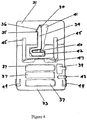
- FIG 4 shows a practical application for fastener 30 illustrated in Figures 1-3 .
- fastener 30 is shown in situ fastening cap 31 to base 33.
- engagement means 36 of fastener 30 engages ledge 35 of cap 31.
- Three batteries 37 provide a power source for electronic module 42, being activated by switch 39.
- Dowels 45 are provided in channels in cap 31 and base 33. These assist in location when cap 31 is being placed on base 33. During release, dowels 45 in conjunction with leaf spring 47 urge cap 31 to separate from base 33.
- Charging contacts 49 can be used to recharge batteries 37 if of the rechargeable type.
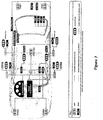
- Figure 5 is an example of integration of the fastening systems of the invention in a typical vehicle CAN network, specifically showing a car door. This illustration is largely self-explanatory. Some of the fasteners of the invention are referred to in Figure 5 as part of the "Intelligent Fastener network". These perform the primary functions of the fastener of the invention, namely to attach components within the vehicle.
- Fastener nodes are performing a secondary function, namely control of the relevant component, such as the window motor, the rear vision mirror, etc. Connection to the CAN bus is also shown.
- FIG 6 is a diagrammatic illustration of part of the system in Figure 5 .
- Some of the fasteners of the invention referred to as "TZ Intelligent Fasteners" are carrying out the primary function discussed above and some are carrying out the secondary function.
- FIG 8 shows how the fasteners of the invention may be arranged to reduce the number of sub-network wiring components through direct connection into the CAN bus.
- Figure 8 should be compared with Figure 6 in this regard.
- each fastener of the invention may be able to act as its own multiplex module/communications gateway or node on the CAN bus.
- This network structure may also enable the fasteners of the invention to extend their function into control of components switching.
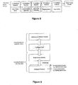
- this illustrates an example of the architecture of a fastening system of the invention in a motor vehicle.
- a fastener of the invention which fastens a component to the vehicle.
- This fastener (the "Intelligent Fastener") is connected to the vehicle computer via the CAN bus.
- the vehicle computer transmits data and/or instructions between the Intelligent Fastener and an "Intelligent Tool” such as a personal digital assistant (hand-held computer).
- the master control resides at the top level of the hierarchy, providing Intelligent Fastener identity and security information to the Intelligent Tool and logging diagnostic and historical fastener function information.
- the Intelligent Fastener may have a primary function of attaching a component to the vehicle and a secondary function of control of switching.
Landscapes
- Engineering & Computer Science (AREA)
- General Engineering & Computer Science (AREA)
- Mechanical Engineering (AREA)
- Chemical & Material Sciences (AREA)
- Combustion & Propulsion (AREA)
- Transportation (AREA)
- Manufacturing & Machinery (AREA)
- Snaps, Bayonet Connections, Set Pins, And Snap Rings (AREA)
- Connection Of Plates (AREA)
- Slide Fasteners, Snap Fasteners, And Hook Fasteners (AREA)
- Clamps And Clips (AREA)
- Lock And Its Accessories (AREA)
Description
- This invention is concerned with fasteners and other assemblies.
- The invention has wide application, as will be apparent from the description below.
- The invention covers a wide range of fasteners, fastening systems, fastener assemblies and related areas. These represent improvements over prior art fasteners and fastener assemblies, etc.
- The document
EP0260132 discloses a fastener according to the preamble of claim 1. - In the invention discussed below, reference is made to material adapted to contract when activated.
- The material adapted to contract when activated is preferably shape memory alloy wire. Shape memory alloys are known and are usually made predominantly or wholly of titanium and nickel. They may also include other material, such as aluminium, zinc and copper. A shape memory alloy is capable of adopting one shape below a predetermined transition temperature and changing to a second shape once its temperature exceeds the transition temperature. Conversely, when the shape memory alloy cools below the transition temperature, it is capable of adopting the first shape again. In connection with the present invention, the shape memory alloy contracts when heated in situ. Shape memory alloy wire currently available, such as that sold under the trade mark Nitinol, is capable of contracting by about 3% when activated by heating.
- Activation of the material adapted to contract when activated is preferably achieved through electrical resistance heating, with a wire feed to the assembly. Activation of the shape memory alloy wire can be initiated from a central location, using the wiring system of, for example, an air craft or automobile. It is also within the scope of this invention that the activation is initiated by remote means, such as a hand held tool operating through the use of any suitable form of energy, including microwave, electric magnetic, sonic, infra-red, radio frequency and so on.
- While activation of the shape memory alloy may take place through heating, other means of activation may be suitable and are within the scope of this invention.
- The fasteners and fastening systems of the invention may be particularly suitable for use in connection with automobiles and to some extent the description below may focus on this application. However, it is to be understood that the scope of the invention is not limited to this application.
- There is a marked trend towards increasing electronic control in motor vehicles. Nowadays, many motor vehicles incorporate computer systems which use a Controller Area Network (CAN) in which modules communicate data to the computer via a bus, or a local interconnect network (LIN) which also enables communication of data via a bus.
- The present invention in some of its aspects is intended to take advantage of the trend towards increased electronic control in vehicles. The present invention provides versions of fasteners which may be suitable for use in vehicles and which may provide significant advantages in relation to assembly of vehicles and service of vehicles. In particular, the fasteners of the present invention may be suitable for connection to a vehicle computer via a CAN or LIN.
- Some fasteners and fastening systems of the invention can be designed to be activated only by authorised parties, such as those engaged in vehicle assembly or servicing. Others can be designed to be operated by vehicle owners.
- In appropriate forms, any of the fasteners and the fastening systems of the invention can have primary and secondary functions, the primary function being to attach components to the vehicle body and the secondary function being the control of component switching. It is possible that use of fastening systems according to the invention may reduce the number of sub-network wiring components required in a vehicle, through direct connection into the CAN bus, for example. In effect, each fastener may become its own multiplex module/communications gateway or node on the CAN bus.
- This invention provides a fastener which represents a variation of a fastener disclosed in International Patent Application No.
PCT/AU03/00759 - Accordingly, this invention provides a fastener according to Claim 1.
- The fastener of the invention is designed so that, when the shape memory alloy contracts, the fastening element flexes or moves about the flex point and the engagement means is drawn out of the engagement position. The fastener may be otherwise as disclosed in International Patent Application No.
PCT/AU03/00759 - The fastener of the invention may be made of any suitable material, including plastic or metal. The fastener may be made of a combination of materials.
- The tensile strength of the beam should be sufficiently high that the fastener can fasten useful loads. Preferably, the material of the beam has sufficient fatigue strength to accommodate the desired number of locked/unlocked cycles.
- The engagement means preferably takes the form of a projecting wedge which can key into a corresponding recess in a wall of an element. Other configurations are possible. For example, the engagement means may be a snap means, a rod for latching over a hook, or an aperture which can latch over a projection such as a peg. The engagement means may take the form of a dovetail on the beam fitting into an appropriate recess.
- The fastener of the invention can engage with an identical fastener, for example.
- Preferably, the shape memory alloy wire takes the form of a titanium-nickel wire which, when sufficient energy in the form of an electrical current is applied, heats to or above a temperature at which the material shrinks by about 4 to 5%. As will be seen from the discussion in connection with the drawings, below, on application of energy such as electrical energy in order to generate heat above a predetermined level, the beam can be caused to move away from the engagement position in which a first element is fastened to a second element, thereby releasing the elements. Conversely, if the shape memory material is permitted to cool below the transitional temperature, in some embodiments the beam may assume the engagement position and the elements may be fastened again.
- The flex point is preferably located forward of the engagement means so as to improve force geometry and to increase the retaining strength of the fastener. An example of this is illustrated in the attached drawings.
- It is preferred that the shape memory alloy wire which contracts when activated is contained in one or more grooves in the beam. This can provide physical protection for the material as well as decreasing heat up/cool down times. It can also reduce ambient temperature effects and increase beam strength. It can enable the beam to maintained in the disengagement position for a desired length of time. This can be regarded as a "hold" state. Such a hold state may be established using less power (such as electrical current) than that required to move the beam from the engagement position to the disengagement position. This may be achieved by insulating the shape memory alloy wire which contracts when activated by being maintained in grooves in the beam.
- It is further preferred that bias means, urging the fastener to the engagement position, is provided. A non-limiting example of such bias means is a leaf spring, preferably of metal. This can urge the material to stretch out once it has cooled and relaxed. It can also greatly reduce any potential for creep deformation in the fastening element when made of plastic.
- Because the beam does not need to bend, it may be made thicker and can have more strength. The beam may be machined, cast, moulded or formed in any desirable way.
- Means intended for engagement by the engagement means may take any suitable form. Some have already been mentioned above, for example part of a snap means, a hook, a peg, a recess or an identical fastener. If the fastener is used for fastening a fuel filler door to a car body, for example, it is preferred that means for engagement by the engagement means is an aperture on the door.
- In this example, the actuating means is preferably actuated either through a suitable switch located on the dash board of the vehicle or through a signal generated from the vehicle key. The latter can be convenient because the driver does not need to remember to actuate the fuel filler door before getting out of the vehicle: the driver needs only to take the vehicle key to the fuel pump and release the fuel filler door while standing next to the vehicle.
- The fastener of the invention may be "intelligent" or not. It may be addressable. It may be part of a network. It may have a switching capacity and it may include sensors. All of these and other information is contained in international patent application No.
PCT/AU03/00759 PCT/AU03/00759 - In an especially preferred embodiment, the fastener includes a microprocessor which can carry out one or more roles. Microprocessor can control the energy delivery to the shape memory alloy wire, preferably by a temperature-dependent algorithm. It can control temperature of the shape memory alloy wire. It can sense the state of the fastener and whether it is engaged or not. It can report this, along with secondary sensed information, to a network of which the fastener forms a part. Preferably, the microprocessor carries out all these roles.
- The invention will now be described in connection with certain non-limiting examples thereof in the accompanying drawings, in which:
-
Figure 1 is a side elevation of the fastener of the invention in the engaged position; -
Figure 2 is the fastener ofFigure 1 in the disengaged position; -
Figure 3 is the fastener ofFigures 1 and 2 in rear elevation; -
Figure 4 shows an embodiment of the fastener ofFigures 1, 2 and 3 in a practical application; -
Figure 5 shows an example of how the fastening systems of the invention may be integrated into a typical vehicle CAN network, in relation to a vehicle door; -
Figure 6 is a diagrammatic illustration of at least part of the system inFigure 5 ; -
Figure 7 shows how the network concept exemplified inFigure 5 and6 may be extended throughout many vehicle components; -
Figure 8 is similar toFigure 6 but gives an example of the extension of the function of fastener system of the invention; -
Figure 9 exemplifies architecture of a fastening system of the invention in a motor vehicle. - Turning to the fastener being an embodiment of the invention and illustrated in
Figures 1 to 3 ,fastener 30 includesfastening element 32 having abeam 34, an engagement means 36 and aflex point 38. As can be seen, flexpoint 38 is separate frombeam 34. - As shown in the rear elevation in
Figure 4 , shapememory alloy wire 40 forms a loop in a groove 44 in the back ofbeam 34 and is attached at each end to electronic module 42.Wire 40 is shown partly in dotted outline inFigures 1 and 2 . - When
wire 40 is heated by a current generated through electronic module 42 andwire 40 reaches a pre-determined temperature, it shrinks as shown inFigure 2 . Fasteningelement 32 bends or flexes atflex point 38 and engagement means 36 is drawn out of engagement with an engaging surface (not shown). As shown inFigure 2 , leaf spring 46 is compressed. Ifwire 40 is allowed to cool, it relaxes and leaf spring 46 decompresses, urging engagement means 36 back into engagement with the engaging surface (not shown). - This embodiment can provide an enhanced positive engagement through engagement means 36 and greater strength to
fastener 30, sincebeam 34 is not required to bend. -
Figure 4 shows a practical application forfastener 30 illustrated inFigures 1-3 . InFigure 4 ,fastener 30 is shown insitu fastening cap 31 tobase 33. As can be seen inFigure 4 , engagement means 36 offastener 30 engagesledge 35 ofcap 31. Threebatteries 37 provide a power source for electronic module 42, being activated byswitch 39. - When
switch 39 is pressed,batteries 37 provide power to electronic module 42, which heats shapememory alloy wire 40 sufficiently to cause shapememory alloy wire 40 to contract. Engagement means 36 is drawn out of contact withledge 35. Cavity 41 is provided incap 31 to allow for this movement ofbeam 34. Whenswitch 39 is pressed,LED 43 lights up to show thatswitch 39 has been activated. -
Dowels 45 are provided in channels incap 31 andbase 33. These assist in location whencap 31 is being placed onbase 33. During release, dowels 45 in conjunction with leaf spring 47urge cap 31 to separate frombase 33. -
Charging contacts 49 can be used to rechargebatteries 37 if of the rechargeable type. -
Figure 5 is an example of integration of the fastening systems of the invention in a typical vehicle CAN network, specifically showing a car door. This illustration is largely self-explanatory. Some of the fasteners of the invention are referred to inFigure 5 as part of the "Intelligent Fastener network". These perform the primary functions of the fastener of the invention, namely to attach components within the vehicle. - Other fasteners referred to in
Figure 5 as "Fastener nodes" are performing a secondary function, namely control of the relevant component, such as the window motor, the rear vision mirror, etc. Connection to the CAN bus is also shown. - It is to be appreciated that the component layout and wiring harness in
Figure 5 is merely an example and not limiting on the scope of the invention. -
Figure 6 is a diagrammatic illustration of part of the system inFigure 5 . Some of the fasteners of the invention, referred to as "TZ Intelligent Fasteners" are carrying out the primary function discussed above and some are carrying out the secondary function. - The primary and secondary functions referred to can be expanded to control or fasten several other vehicle components, such as those shown in
Figure 7 . This Figure is self- explanatory. -
Figure 8 shows how the fasteners of the invention may be arranged to reduce the number of sub-network wiring components through direct connection into the CAN bus.Figure 8 should be compared withFigure 6 in this regard. In effect, each fastener of the invention may be able to act as its own multiplex module/communications gateway or node on the CAN bus. This network structure may also enable the fasteners of the invention to extend their function into control of components switching. - With reference to
Figure 9 , this illustrates an example of the architecture of a fastening system of the invention in a motor vehicle. At the bottom of the chain is a fastener of the invention, which fastens a component to the vehicle. This fastener (the "Intelligent Fastener") is connected to the vehicle computer via the CAN bus. The vehicle computer transmits data and/or instructions between the Intelligent Fastener and an "Intelligent Tool" such as a personal digital assistant (hand-held computer). - The master control resides at the top level of the hierarchy, providing Intelligent Fastener identity and security information to the Intelligent Tool and logging diagnostic and historical fastener function information.
- As before, the Intelligent Fastener may have a primary function of attaching a component to the vehicle and a secondary function of control of switching.
- It will be apparent to one skilled in the art that the invention has wide industrial applicability, providing fasteners, fastening systems and other aspects for a plurality of industries.
Claims (11)
- A fastener (30) which includes:(a) a fastening element (32) having a beam (34), an engagement means (36) disposed at one end of the beam and a base disposed at the other end of the beam; and(b) actuating means attached to the fastening element (32) and including shape memory alloy wire (40) wire formed in a loop in a groove (44) in the back of the beam (34) and attached at each end to an electronic module (42), the wire adapted to contract when activated by the electronic module;characterised in that:the engagement means (36) is located on one side of the beam (34);the beam (34) is movable, upon contraction of the wire, from an engagement position to a disengagement position; andthe base has a first arm and a second arm joined by a flex point (38), separate from the beam, the beam (34) being located at one end of the first arm and the flex point (38) being located at the other end of the first arm, on the same side of the beam (34) as the engagement means (36), and forward of the engagement means, wherein the flex point facilitates movement of the beam without bending the beam, and wherein a leaf spring (46) is located between the first and second arms.
- The fastener (30) of claim 1, wherein the engagement means (36) is located at or towards one end of the beam (34) of the fastening element (32).
- The fastener (30) of claim 2, wherein the engagement means (36) includes a projecting wedge.
- The fastener (30) of claim 3, wherein the one or more grooves are located on one side of the beam (34) and the engagement means (36) is located on the opposite side of the beam (34).
- The fastener (30) of any one of claims 1 to 4, wherein the beam (34) is integral with the base.
- The fastener (30) of any one of claims 1 to 5, which includes a microprocessor.
- The fastener (30) of claim 6, wherein the microprocessor is adapted to control energy delivery to the shape memory alloy wire (40).
- The fastener (30) of claim 6 or claim 7, wherein the microprocessor is adapted to sense whether the engagement means (36) is engaged or disengaged.
- The fastener (30) of any one of claims 6 to 8, wherein the microprocessor is adapted to control temperature of the shape memory alloy wire (40).
- The fastener (30) of claim 8, wherein the microprocessor is adapted to provide a report on whether the engagement means (36) is engaged or disengaged.
- The fastener (30) of claim 10, wherein the microprocessor is adapted to provide the report to a network of which the fastener (30) forms a part.
Priority Applications (2)
| Application Number | Priority Date | Filing Date | Title |
|---|---|---|---|
| EP10196662.0A EP2302229B1 (en) | 2003-11-17 | 2004-11-17 | Shape memory releasable fastening system |
| EP10196668.7A EP2302230B1 (en) | 2003-11-17 | 2004-11-17 | Shape memory fastener assembly |
Applications Claiming Priority (7)
| Application Number | Priority Date | Filing Date | Title |
|---|---|---|---|
| AU2003906324A AU2003906324A0 (en) | 2003-11-17 | Improved framing system | |
| AU2004901371A AU2004901371A0 (en) | 2004-03-16 | Multipoint fasteners and releaseable fastening system | |
| PCT/AU2004/000623 WO2004101216A1 (en) | 2003-05-13 | 2004-05-13 | Improved assembly and disassembly method, system and component |
| AU2004903861A AU2004903861A0 (en) | 2004-07-14 | Inline and other fasteners | |
| AU2004904582A AU2004904582A0 (en) | 2004-08-13 | Further improvements in inline and other fasteners | |
| AU2004905399A AU2004905399A0 (en) | 2004-09-20 | Assembly for partial release, stud fastener and manual override | |
| PCT/AU2004/001580 WO2005047714A1 (en) | 2003-11-17 | 2004-11-17 | Fasteners and other assemblies |
Related Child Applications (4)
| Application Number | Title | Priority Date | Filing Date |
|---|---|---|---|
| EP10196662.0A Division-Into EP2302229B1 (en) | 2003-11-17 | 2004-11-17 | Shape memory releasable fastening system |
| EP10196662.0A Division EP2302229B1 (en) | 2003-11-17 | 2004-11-17 | Shape memory releasable fastening system |
| EP10196668.7A Division-Into EP2302230B1 (en) | 2003-11-17 | 2004-11-17 | Shape memory fastener assembly |
| EP10196668.7A Division EP2302230B1 (en) | 2003-11-17 | 2004-11-17 | Shape memory fastener assembly |
Publications (3)
| Publication Number | Publication Date |
|---|---|
| EP1697642A1 EP1697642A1 (en) | 2006-09-06 |
| EP1697642A4 EP1697642A4 (en) | 2008-04-09 |
| EP1697642B1 true EP1697642B1 (en) | 2018-05-30 |
Family
ID=36791141
Family Applications (3)
| Application Number | Title | Priority Date | Filing Date |
|---|---|---|---|
| EP04797029.8A Expired - Lifetime EP1697642B1 (en) | 2003-11-17 | 2004-11-17 | Fasteners and other assemblies |
| EP10196668.7A Expired - Lifetime EP2302230B1 (en) | 2003-11-17 | 2004-11-17 | Shape memory fastener assembly |
| EP10196662.0A Expired - Lifetime EP2302229B1 (en) | 2003-11-17 | 2004-11-17 | Shape memory releasable fastening system |
Family Applications After (2)
| Application Number | Title | Priority Date | Filing Date |
|---|---|---|---|
| EP10196668.7A Expired - Lifetime EP2302230B1 (en) | 2003-11-17 | 2004-11-17 | Shape memory fastener assembly |
| EP10196662.0A Expired - Lifetime EP2302229B1 (en) | 2003-11-17 | 2004-11-17 | Shape memory releasable fastening system |
Country Status (6)
| Country | Link |
|---|---|
| US (4) | US7610783B2 (en) |
| EP (3) | EP1697642B1 (en) |
| JP (3) | JP5261638B2 (en) |
| CN (3) | CN102400990B (en) |
| AU (1) | AU2004289712A1 (en) |
| WO (1) | WO2005047714A1 (en) |
Families Citing this family (114)
| Publication number | Priority date | Publication date | Assignee | Title |
|---|---|---|---|---|
| JP5261638B2 (en) * | 2003-11-17 | 2013-08-14 | テレズィゴロジー インク. | Fastener |
| EP1787033A1 (en) * | 2004-07-14 | 2007-05-23 | Telezygology Inc. | Release for fastening assembly |
| WO2006072131A1 (en) * | 2005-01-05 | 2006-07-13 | Telezygology Inc | Panel and clamping fasteners |
| EP1841647A1 (en) | 2005-01-14 | 2007-10-10 | Telezygology Inc. | Securing systems |
| CN101107413A (en) * | 2005-01-20 | 2008-01-16 | 远程接合技术公司 | locking system |
| AU2012233060B2 (en) * | 2005-04-04 | 2015-09-24 | Telezygology Inc | Stud fastener and stabilising device |
| US7854580B2 (en) | 2005-04-04 | 2010-12-21 | Telezygology Inc. | Stud fastener and stabilising device |
| US20080226421A1 (en) * | 2005-08-16 | 2008-09-18 | Dickory Rudduck | Locking Assembly |
| TW200720563A (en) | 2005-08-16 | 2007-06-01 | Telezygology Inc | Locking assembly |
| JP2009510365A (en) | 2005-10-04 | 2009-03-12 | テレズィゴロジー インク | Electronic information transmission system |
| NO323808B1 (en) * | 2005-11-16 | 2007-07-09 | Spilka Ind As | Center frame bracket for attaching a window hinge to a window frame. |
| ATE556233T1 (en) * | 2005-12-12 | 2012-05-15 | Telezygology Inc | DEVELOPMENTS IN FASTENING ELEMENTS WITH FLEXIBLE SUPPORTS |
| WO2007068034A1 (en) * | 2005-12-12 | 2007-06-21 | Telezygology Inc. | Instrument panel |
| US8720722B2 (en) * | 2005-12-15 | 2014-05-13 | Cornerstone Research Group, Inc. | Venting mechanism for containers |
| TWI296679B (en) * | 2006-02-20 | 2008-05-11 | Delta Electronics Inc | Disassembly-prevention mechanism |
| WO2008030797A2 (en) * | 2006-09-06 | 2008-03-13 | Telezygology, Inc. | Locking strut |
| US7770959B2 (en) * | 2006-10-30 | 2010-08-10 | Gm Global Technology Operations, Inc. | Door actuation systems using active materials |
| JP5537946B2 (en) | 2006-11-22 | 2014-07-02 | ブリストル−マイヤーズ スクイブ カンパニー | Targeted therapeutic agents based on modified proteins for tyrosine kinase receptors including IGF-IR |
| GB0707756D0 (en) | 2007-04-23 | 2007-05-30 | Rolls Royce Plc | A joint for a shape memory material |
| WO2008134699A1 (en) * | 2007-04-30 | 2008-11-06 | Telezygology, Inc. | Developments in smart memory alloy retention |
| US8282153B2 (en) * | 2007-08-31 | 2012-10-09 | GM Global Technology Operations LLC | Active material based seam concealment device |
| US7905538B2 (en) | 2007-08-31 | 2011-03-15 | Gm Global Technology Operations, Inc. | Active material based concealment devices for seams |
| FR2926343B1 (en) * | 2008-01-14 | 2012-01-13 | Peugeot Citroen Automobiles Sa | ASSEMBLY ASSEMBLY AND DISASSEMBLY OF A REMOVABLE CLIP FOR ATTACHING A WORKPIECE |
| JP2011517314A (en) | 2008-02-14 | 2011-06-02 | ブリストル−マイヤーズ スクイブ カンパニー | Targeted therapeutics based on engineered proteins that bind to EGFR |
| US9253931B2 (en) | 2008-03-31 | 2016-02-02 | Telezygology, Inc. | Computer room security |
| PE20091931A1 (en) | 2008-05-22 | 2009-12-31 | Bristol Myers Squibb Co | MULTIVALENT FIBRONECTIN-BASED FRAME DOMAIN PROTEINS |
| WO2010027822A1 (en) * | 2008-08-25 | 2010-03-11 | Telezygology, Inc. | System for aircraft |
| US20100095493A1 (en) * | 2008-10-16 | 2010-04-22 | Convertible Shoe, Llc | Locking mechanism |
| TWI496582B (en) | 2008-11-24 | 2015-08-21 | 必治妥美雅史谷比公司 | Bispecific egfr/igfir binding molecules |
| US8741464B2 (en) * | 2009-02-27 | 2014-06-03 | Motorola Solutions, Inc. | Inertia enhanced latching system |
| US20120096910A1 (en) * | 2009-04-14 | 2012-04-26 | Cary Maguire | Key Release Stud |
| JP2010284984A (en) * | 2009-06-09 | 2010-12-24 | Fuji Heavy Ind Ltd | Vehicle battery mounting structure |
| CN102056802A (en) * | 2009-09-03 | 2011-05-11 | 斯平玛斯特有限公司 | Biased releasable connection system |
| US8464982B2 (en) * | 2009-10-05 | 2013-06-18 | Jamco America, Inc. | Systems and methods for securing and protecting aircraft line replaceable units with status indicator under a passenger seat |
| US9562089B2 (en) | 2010-05-26 | 2017-02-07 | Bristol-Myers Squibb Company | Fibronectin based scaffold proteins having improved stability |
| US9131742B2 (en) | 2010-05-27 | 2015-09-15 | Christopher D. Gowen | Chinstrap to helmet connector |
| US8801324B2 (en) * | 2010-08-17 | 2014-08-12 | Production Resource Group, L.L.C | Cable slider with symmetric pieces |
| WO2012024739A1 (en) * | 2010-08-27 | 2012-03-01 | Telezygology Inc. | Locking system |
| KR101403026B1 (en) * | 2010-10-29 | 2014-06-03 | 한국전자통신연구원 | Shockless separation device for space application |
| US8708322B2 (en) | 2010-11-05 | 2014-04-29 | Honeywell International Inc. | Payload launch lock mechanism |
| WO2012125360A2 (en) | 2011-03-17 | 2012-09-20 | A. Raymond Et Cie | Smart material actuated fasteners |
| US20130042461A1 (en) * | 2011-08-17 | 2013-02-21 | Composite Technology Development, Inc. | Shape memory polymer devices |
| FI124681B (en) * | 2011-10-28 | 2014-12-15 | Abloy Oy | Padlock |
| US9422958B2 (en) | 2012-01-26 | 2016-08-23 | Empire Technology Development Llc | Sprung latch fastener |
| US9107464B2 (en) * | 2012-10-02 | 2015-08-18 | No Limit Safety, LLC | Quick release device for safety helmet |
| CN102913517B (en) * | 2012-11-01 | 2014-07-30 | 慧明光电(深圳)有限公司 | Coaxial automatic lock capable of being tightened |
| US20140260453A1 (en) * | 2013-03-15 | 2014-09-18 | Dewalch Technologies, Inc. | Electronic locking apparatus and method |
| US10822835B2 (en) | 2013-03-15 | 2020-11-03 | Dewalch Technologies, Inc. | Electronic locking apparatus and method |
| US20140348581A1 (en) * | 2013-05-24 | 2014-11-27 | Soucy International Inc. | Mounting System for a Vehicle and Method of Using the Same |
| JP6103532B2 (en) * | 2013-05-30 | 2017-03-29 | 株式会社Ihiエアロスペース | Flying object launcher |
| CN105378195B (en) | 2013-07-12 | 2018-04-17 | Invue安全产品公司 | For the merchandise security devices being used together with electron key |
| US9496666B2 (en) | 2014-01-09 | 2016-11-15 | Armstrong Aerospace, Inc. | Aircraft power and data distribution system and methods of performing the same |
| US9017092B1 (en) | 2014-05-07 | 2015-04-28 | Microsoft Technology Licensing, Llc | Electronic connector |
| GB2541127A (en) * | 2014-06-30 | 2017-02-08 | Halliburton Energy Services Inc | Shape-memory alloy actuated fastener |
| RU2693970C2 (en) * | 2014-10-20 | 2019-07-08 | Бик-Виолекс Са | Cassette with shaving razors and shaver containing such cassette with razors for shaving |
| US9862115B2 (en) * | 2015-03-27 | 2018-01-09 | Intel Corporation | Hidden feature for accessing or repairing mobile devices |
| US9728915B2 (en) | 2015-05-19 | 2017-08-08 | Microsoft Technology Licensing, Llc | Tapered-fang electronic connector |
| DE102015209320A1 (en) * | 2015-05-21 | 2016-04-21 | Schaeffler Technologies AG & Co. KG | fuse element |
| US9739568B2 (en) | 2015-09-10 | 2017-08-22 | The Boeing Company | Methods of connecting testing equipment to a missile system |
| US9740245B2 (en) | 2015-10-05 | 2017-08-22 | Microsoft Technology Licensing, Llc | Locking mechanism |
| FR3045513B1 (en) * | 2015-12-21 | 2018-01-19 | Psa Automobiles Sa. | ATTACHING AN ACTUATOR TO A HOUSING OF A FUEL HOPPER |
| EP3405063B1 (en) * | 2016-01-21 | 2020-04-29 | Avaitec AB | A fastening device and a fastening system |
| US9660380B1 (en) | 2016-01-22 | 2017-05-23 | Microsoft Technology Licensing, Llc | Alignment tolerant electronic connector |
| CN107465800A (en) * | 2016-06-06 | 2017-12-12 | 华为终端(东莞)有限公司 | The tripper and mobile terminal of a kind of mobile terminal |
| IL247012B (en) * | 2016-07-28 | 2021-05-31 | Marom Dolphin Ltd | Connector |
| CN106037535B (en) * | 2016-08-11 | 2022-03-08 | 广东美的生活电器制造有限公司 | Grinder and its connecting ring and soymilk maker |
| MX387787B (en) * | 2016-09-19 | 2025-03-18 | Panduit Corp | DISPLAY MODULE FOR VOLTAGE INDICATOR. |
| US10914397B2 (en) * | 2016-10-14 | 2021-02-09 | Schneider Electric Buildings, Llc | Self aligning and self latching mechanical shaft connector |
| CN108266069A (en) * | 2016-12-30 | 2018-07-10 | 南京江宁公共交通信息科技有限公司 | Without stake public bicycles smart lock |
| JP7206208B2 (en) | 2017-03-01 | 2023-01-17 | キャリア コーポレイション | collet latch |
| US10511599B2 (en) | 2017-03-13 | 2019-12-17 | Microsoft Technology Licensing, Llc | System to filter impossible user travel indicators |
| EP3615850B1 (en) | 2017-04-23 | 2021-05-19 | Plasan Re'em Ltd. | A system for bonding a windshield to a windshield frame |
| US10455900B2 (en) * | 2017-05-18 | 2019-10-29 | Feinstein Patents, Llc | Bi-stable strap with a snap spring hinge |
| US10794093B2 (en) | 2017-05-19 | 2020-10-06 | Microsoft Technology Licensing, Llc | Method of optimizing memory wire actuator energy output |
| CN107215205B (en) * | 2017-05-24 | 2020-05-12 | 内蒙古北方重型汽车股份有限公司 | Mining automobile oil tank with dustproof, antitheft and anti-drop functions |
| US10445533B2 (en) | 2017-06-30 | 2019-10-15 | Microsoft Technology Licensing, Llc | Method of optimizing memory wire actuator energy output |
| AU2018214004A1 (en) | 2017-08-07 | 2019-02-21 | Telezygology Inc | Lockout/Tagout System |
| CN107575454A (en) * | 2017-09-19 | 2018-01-12 | 珠海格力电器股份有限公司 | Buckle structure and buckle connecting device |
| US10303214B2 (en) | 2017-10-17 | 2019-05-28 | Microsoft Technology Licensing, Llc | Docking mechanisms and methods of restraining two portions of a computing device |
| US10893724B2 (en) * | 2017-11-01 | 2021-01-19 | Microsoft Technology Licensing, Llc | Locking mechanisms in electronic devices |
| DE102017220505B4 (en) * | 2017-11-16 | 2024-03-28 | Te Connectivity Germany Gmbh | Connection element for mechanical and electrical connection to a contact element of an electrical storage cell, in particular a contact lug of a pouch cell, and electrical storage cell module |
| CN107816474B (en) * | 2017-11-27 | 2023-05-23 | 长春理工大学 | Locking device of space rotating mechanism based on memory alloy wire |
| US10511127B2 (en) | 2018-03-20 | 2019-12-17 | Microsoft Technology Licensing, Llc | High-speed electronic connector |
| CN110638204B (en) * | 2018-06-27 | 2023-01-03 | 浙江新益申高机械传动有限公司 | Table top support member and locking member for the same |
| US12012983B2 (en) * | 2018-07-12 | 2024-06-18 | Leonardo S.R.L. | Actuation and blocking system of a joint between a shoulder and a shelf of furniture or other furnishing items |
| CN111322292B (en) * | 2018-12-14 | 2021-05-11 | 盟倍力股份有限公司 | snap mechanism |
| CN109519050A (en) * | 2018-12-31 | 2019-03-26 | 杭州天启钛智能科技有限公司 | A kind of smart lock and lock control system |
| FR3091909B1 (en) * | 2019-01-21 | 2021-02-26 | A Raymond Et Cie | MULTI-STUD FIXING DEVICE GENERATING A TENSIONING, AND FIXING METHOD OF SUCH A DEVICE |
| US11015736B1 (en) * | 2019-01-24 | 2021-05-25 | Vector Ring LLC | Clamp utilizing a shape memory alloy actuator to shutoff, squeeze off, plastic pipe and tubing used in the pressurized transmission of gas or fluid |
| CN109881991B (en) * | 2019-04-12 | 2024-06-07 | 深圳芯邦科技股份有限公司 | Lock |
| US11236884B2 (en) * | 2019-09-05 | 2022-02-01 | Aptiv Limited Technologies | Vehicle lighting assembly with lens heating device and receptacle connector assembly for same |
| EP4028136A4 (en) | 2019-09-10 | 2023-10-04 | Vitruvian Investments Pty Ltd | Fitness training apparatus and system |
| US12152628B1 (en) * | 2019-10-03 | 2024-11-26 | Cornerstone Research Group, Inc. | Reversible joining device and method |
| US11283228B2 (en) | 2019-11-12 | 2022-03-22 | Toyota Motor Engineering And Manufacturing North America, Inc. | Universal adapter for sensors |
| CN111021851B (en) * | 2019-12-27 | 2024-11-08 | 宁波岚骐智能科技有限公司 | Locking device |
| US20210220813A1 (en) * | 2020-01-16 | 2021-07-22 | Johnson Matthey Public Limited Company | Pallet for supporting a catalyst monolith during coating |
| WO2021194508A1 (en) * | 2020-03-27 | 2021-09-30 | Hewlett-Packard Development Company, L.P. | Accessibility within enclosures of computing devices background |
| CN111894954B (en) * | 2020-06-28 | 2022-03-04 | 航天东方红卫星有限公司 | A memory alloy spring pin |
| US11618521B2 (en) * | 2020-07-09 | 2023-04-04 | Zhejiang CFMOTO Power Co., Ltd. | Quick connect and disconnect latch mechanism for mounting accessories on offroad vehicles |
| CN112109535B (en) * | 2020-08-25 | 2022-02-01 | 东风汽车集团有限公司 | Battery locking mechanism |
| CN113007188B (en) * | 2021-03-24 | 2022-05-31 | 联想(北京)有限公司 | Connection structure and electronic equipment |
| CN113386161B (en) * | 2021-07-05 | 2022-08-30 | 四川中科彭成机器人技术有限公司 | Creep-resistant rope-driven mechanical finger |
| CN113560843B (en) * | 2021-08-23 | 2022-05-20 | 江西晶浩光学有限公司 | Circuit board mounting structure, periscopic camera module and assembling method thereof |
| US11871550B2 (en) | 2021-10-22 | 2024-01-09 | International Business Machines Corporation | Motor controlled retractable EMC protection |
| US11751362B2 (en) | 2021-10-22 | 2023-09-05 | International Business Machines Corporation | Thermally activated retractable EMC protection |
| US11695240B2 (en) | 2021-10-22 | 2023-07-04 | International Business Machines Corporation | Retractable EMC protection |
| WO2023087059A1 (en) * | 2021-11-16 | 2023-05-25 | Vitruvian Investments Pty Ltd | Fitness training apparatus, and computer-implemented method and system of fitness training |
| US12100910B2 (en) | 2021-12-06 | 2024-09-24 | International Business Machines Corporation | Shape-memory alloy lock for connectors |
| USD1037033S1 (en) | 2021-12-10 | 2024-07-30 | Panduit Corp. | Absence of voltage display device |
| CN114800441B (en) * | 2022-03-19 | 2023-07-07 | 中国人民解放军空军军医大学 | Heterogeneous knee joint of lower extremity exoskeleton based on parallel elastomers |
| US12168892B2 (en) * | 2022-03-21 | 2024-12-17 | Sunshine Enclosures LLC | Pressure sensitive flexible button lock and retractable package thereof |
| US12134355B2 (en) * | 2022-06-23 | 2024-11-05 | GM Global Technology Operations LLC | Energy attenuating display mount for dash mounted vehicle display |
| TWI857422B (en) * | 2022-12-15 | 2024-10-01 | 宏碁股份有限公司 | Socket connector |
| EP4494986A1 (en) * | 2023-07-18 | 2025-01-22 | SKS metaplast Scheffer-Klute GmbH | Holding device |
Citations (1)
| Publication number | Priority date | Publication date | Assignee | Title |
|---|---|---|---|---|
| EP0260132A2 (en) * | 1986-09-10 | 1988-03-16 | The Furukawa Electric Co., Ltd. | Electronic connector |
Family Cites Families (108)
| Publication number | Priority date | Publication date | Assignee | Title |
|---|---|---|---|---|
| US968036A (en) * | 1909-05-12 | 1910-08-23 | Edward Erickson | Fastening device. |
| US1268278A (en) * | 1916-06-03 | 1918-06-04 | Charles Read | Garment-fastener. |
| US1300337A (en) * | 1918-04-11 | 1919-04-15 | G W J Murphy Company | Stud-and-socket fastener. |
| US1513710A (en) * | 1924-01-28 | 1924-10-28 | Autoyre Company | Separable fastener |
| US1804387A (en) * | 1928-08-11 | 1931-05-12 | Ingersoll Magnetic Lock Compan | Automobile hood lock |
| US1747092A (en) * | 1928-12-13 | 1930-02-11 | Arthur Ambrose Van Note | Automobile hood fastener |
| US2200346A (en) * | 1937-04-14 | 1940-05-14 | Gustave H Sepull | Engine hand latch |
| US2380568A (en) * | 1944-01-21 | 1945-07-31 | Arthur R Adams | Fastener |
| US2401981A (en) * | 1944-08-17 | 1946-06-11 | Metal Textile Corp | Self-acting friction clutch |
| US2526790A (en) * | 1945-04-25 | 1950-10-24 | Frederick Archibald Pillet | Fastening device |
| US2614781A (en) * | 1949-06-16 | 1952-10-21 | William A Engel | Aircraft seat leg release means |
| US2817551A (en) * | 1953-08-03 | 1957-12-24 | Claude Sintz Inc | Ball joint assembly |
| US2749165A (en) * | 1954-05-10 | 1956-06-05 | Albert L Coulter | Hood latch adapter |
| US2841430A (en) * | 1955-07-21 | 1958-07-01 | Chicago Forging & Mfg Co | Hood latch |
| US2863690A (en) * | 1955-11-04 | 1958-12-09 | Atvidabergs Butiksingredningar | Fittings for coupled windows |
| US3235299A (en) * | 1962-02-02 | 1966-02-15 | Murray Mfg Corp | Wire spring catch for doors |
| DE1450910A1 (en) | 1965-08-16 | 1969-08-28 | Auer Ulrich Wolfgang | Shrinking connector |
| DE1815720C3 (en) * | 1968-12-13 | 1980-06-12 | Bosch-Siemens Hausgeraete Gmbh, 7000 Stuttgart | Locking device for the loading door of a washing machine |
| US3601434A (en) * | 1969-11-24 | 1971-08-24 | Gen Motors Corp | Hood latching arrangement |
| GB1312557A (en) * | 1971-02-19 | 1973-04-04 | Anderton Springs Ltd | Circlip |
| DE2256744A1 (en) * | 1972-11-18 | 1974-06-06 | Messerschmitt Boelkow Blohm | DEVICE FOR FIXING FLEXIBLE FUEL TANK IN THE PLANE |
| US4117701A (en) * | 1977-01-20 | 1978-10-03 | Luigi Giovanni Del Mei | Electro-thermal lock |
| DE2829925A1 (en) * | 1978-07-07 | 1980-01-24 | Fichtel & Sachs Ag | LOCKING AND / OR LOCKING DEVICE WITH VEHICLE DOORS |
| FR2480342A1 (en) * | 1980-04-14 | 1981-10-16 | Renault | ELECTRIC LOCK MECHANISM FOR THE TRUNK DOOR OF A MOTOR VEHICLE |
| JPS606652Y2 (en) * | 1982-09-01 | 1985-03-04 | 戌 中川 | Fastener |
| JPS59144645A (en) * | 1983-02-04 | 1984-08-18 | 村田機械株式会社 | Controller of holding hook of dobby machine |
| US4772112A (en) * | 1984-11-30 | 1988-09-20 | Cvi/Beta Ventures, Inc. | Eyeglass frame including shape-memory elements |
| JPH0670429B2 (en) * | 1985-04-03 | 1994-09-07 | 時枝 直満 | Linear motion type actuator |
| US4753465A (en) * | 1986-04-11 | 1988-06-28 | James F. Dalby | Remotely operable locking mechanism |
| JPH053065Y2 (en) * | 1986-12-18 | 1993-01-26 | ||
| JPS63195022A (en) * | 1987-02-09 | 1988-08-12 | Aisan Ind Co Ltd | Evaporated fuel conducting device in fuel tank |
| JPH082351Y2 (en) * | 1987-12-02 | 1996-01-24 | 富士重工業株式会社 | Automatic lid locking system for automobiles |
| JPH079339B2 (en) * | 1988-03-11 | 1995-02-01 | 株式会社東芝 | Control device for refrigerator door lock mechanism |
| JPH0238706A (en) * | 1988-07-29 | 1990-02-08 | Hitachi Metals Ltd | Method of connecting axis body |
| US5119555A (en) * | 1988-09-19 | 1992-06-09 | Tini Alloy Company | Non-explosive separation device |
| FR2639106B1 (en) * | 1988-11-15 | 1990-12-21 | Thomson Brandt Armements | DEVICE FOR LOCKING AND UNLOCKING TWO ELEMENTS OF A PROJECTILE, PARTICULARLY A PARACHUTE POT |
| FR2648199B1 (en) | 1989-06-09 | 1991-09-27 | Aerospatiale | TEMPORARY LINK DEVICE, PARTICULARLY FOR ARTIFICIAL SATELLITE APPENDIX, AND METHOD FOR RELEASING SUCH A LINK |
| US4974885A (en) * | 1989-10-31 | 1990-12-04 | Fuji Jukogyo Kabushiki Kaisha | Device for locking trunk lid of motor vehicle |
| US5129753A (en) | 1990-11-13 | 1992-07-14 | Trw Inc. | Shape memory wire latch mechanism |
| GB9102006D0 (en) | 1991-01-30 | 1991-03-13 | Lucas Ind Plc | Screening arrangement for connectors |
| US5120175A (en) * | 1991-07-15 | 1992-06-09 | Arbegast William J | Shape memory alloy fastener |
| US5192147A (en) * | 1991-09-03 | 1993-03-09 | Lockheed Missiles & Space Company, Inc. | Non-pyrotechnic release system |
| US5312152A (en) | 1991-10-23 | 1994-05-17 | Martin Marietta Corporation | Shape memory metal actuated separation device |
| FR2684141B1 (en) | 1991-11-26 | 1995-06-16 | Creusot Loire | DEVICE FOR DRIVING A ROTATING GAS BREWING TURBINE INSIDE AN OVEN. |
| US5160233A (en) | 1992-05-13 | 1992-11-03 | The United State Of America As Representd By The Administrator Of The National Aeronautics And Space Administration | Fastening apparatus having shape memory alloy actuator |
| US5193929A (en) | 1992-06-01 | 1993-03-16 | The United States Of America As Represented By The Administrator Of The National Aeronautics And Space Administration | Method and apparatus for preloading a joint by remotely operable means |
| US5456243A (en) | 1992-07-30 | 1995-10-10 | Jones; Robert F. | Thermal block for door assembly |
| US5248233A (en) | 1992-09-25 | 1993-09-28 | Webster Richard G | No-shock separation mechanism |
| US5536126A (en) | 1994-06-10 | 1996-07-16 | Hughes Aircraft Company | Assembly with solid state, phase transformable locking fastener |
| US5630671A (en) | 1995-08-31 | 1997-05-20 | The Torrington Company | Locking device for a bearing assembly |
| US5771742A (en) | 1995-09-11 | 1998-06-30 | Tini Alloy Company | Release device for retaining pin |
| US5618066A (en) * | 1995-11-13 | 1997-04-08 | Fu-Hsiang; Chen | Automatic latch device |
| US6543976B1 (en) | 1996-05-03 | 2003-04-08 | Senco Products, Inc. | Fastening device |
| FR2748987B1 (en) | 1996-05-22 | 1998-11-06 | Aerospatiale | TEMPORARY LOCKING SYSTEM FOR MOVING TWO BODIES IN RELATION TO ONE ANOTHER, AT LEAST ONE SENSE OF A PREDETERMINED DIRECTION |
| US5722709A (en) | 1996-10-30 | 1998-03-03 | Hughes Electronics | Separation device using a shape memory alloy retainer |
| DE19649739C2 (en) | 1996-11-30 | 1998-11-12 | Daimler Benz Aerospace Ag | Release device for hold-down z. B. on solar generators |
| GB2320277B (en) | 1996-12-09 | 2001-10-10 | Univ Brunel | Improvements relating to product disassembly |
| US6126115A (en) | 1997-01-21 | 2000-10-03 | Lockheed Martin Corporation | Apparatus for retaining and releasing a payload |
| JPH11111407A (en) * | 1997-10-03 | 1999-04-23 | Fujitsu Ltd | Connector surface mounting method and connector |
| JPH11224455A (en) * | 1998-02-05 | 1999-08-17 | Nec Corp | Locking device |
| AUPP247798A0 (en) | 1998-03-18 | 1998-04-23 | Rudduck, Dickory | Fixing and release systems |
| US6349767B2 (en) | 1998-05-13 | 2002-02-26 | Halliburton Energy Services, Inc. | Disconnect tool |
| US6175989B1 (en) | 1998-05-26 | 2001-01-23 | Lockheed Corp | Shape memory alloy controllable hinge apparatus |
| DE19826539A1 (en) | 1998-06-15 | 1999-12-16 | Esselte Nv | Binding element for binding a stack of documents consisting of loose sheets |
| GB9818052D0 (en) | 1998-08-20 | 1998-10-14 | British Aerospace | Fastening arrangements |
| DE19843965C2 (en) | 1998-09-24 | 2000-07-13 | Daimler Chrysler Ag | Hold and release mechanism with a shape memory actuator |
| US6467987B1 (en) | 1999-03-29 | 2002-10-22 | Honeywell International Inc. | Resettable non-explosive actuator |
| US6310411B1 (en) * | 1999-04-21 | 2001-10-30 | Hewlett-Packard Company | Lock assembly for a personal computer enclosure |
| US6450064B1 (en) | 1999-05-20 | 2002-09-17 | Starsys Research Corporation | Resettable separation mechanism with anti-friction bearings |
| JP2001015956A (en) * | 1999-06-30 | 2001-01-19 | Nec Corp | Method for disconnecting mounted component from enclosure of electronic device, connecting structure, and electronic device |
| US6451239B1 (en) * | 1999-08-23 | 2002-09-17 | Robert B. Wilson | Process of making a hook fastener using radio frequency heating |
| US6474987B1 (en) * | 1999-09-03 | 2002-11-05 | Mitsubishi Materials Silicon Corporation | Wafer holder |
| US6321654B1 (en) | 2000-02-22 | 2001-11-27 | The United States Of America As Represented By The Secretary Of The Army | Microelectromechanical systems (MEMS) -type devices having latch release and output mechanisms |
| AU2001257630A1 (en) * | 2000-05-03 | 2001-11-12 | The Regents Of The University Of Michigan | Attachment mechanism |
| US6769830B1 (en) | 2000-07-05 | 2004-08-03 | Lockheed Martin Corporation | Connector assembly |
| AUPQ885500A0 (en) * | 2000-07-19 | 2000-08-10 | Telezygology Pty Limited | Enhancement of products |
| AUPQ902900A0 (en) * | 2000-07-27 | 2000-08-17 | Stephen-Daly, Paul | Deterrent device for theft or unauthorised use of appliances |
| US6780042B1 (en) | 2000-08-03 | 2004-08-24 | Rutgers, The State University Of New Jersey | Active quick connecting/disconnecting connector |
| EP1180569A3 (en) * | 2000-08-09 | 2003-08-06 | ITW Limited | Locking or latching mechanism |
| US6474702B1 (en) | 2000-08-16 | 2002-11-05 | France/Scott Fetzer Company | Range door lock with nuisance latch |
| US6494822B1 (en) | 2000-09-01 | 2002-12-17 | Unova Ip Corp | Tool retention mechanism |
| ES2188331B1 (en) | 2000-09-20 | 2004-06-16 | Sener, Ingenieria Y Sistemas, S.A. | MECHANISM OF LOOP AND RELEASE OF EQUIPMENT WITH REMOTE ACTION. |
| GB2370322B (en) * | 2000-12-20 | 2003-03-12 | Fmc Corp | Metallic seal components |
| US6530718B2 (en) | 2001-01-30 | 2003-03-11 | Lockheed Martin Corporation | Connector assembly |
| AUPR385101A0 (en) * | 2001-03-20 | 2001-04-12 | Telezygology Pty Limited | Internal jigging |
| EP1245762B1 (en) * | 2001-03-27 | 2004-01-28 | C.R.F. Società Consortile per Azioni | Door latch |
| US6779955B2 (en) | 2001-05-31 | 2004-08-24 | Evgeny I. Rivin | Mechanical contact connection |
| EP1279784A1 (en) * | 2001-07-27 | 2003-01-29 | Oxford Automotive Italia di Gessaroli S.r.l. | Motor-vehicle door lock, particularly for a rear door or a bonnet, having shape memory actuating means |
| FR2833543B1 (en) * | 2001-12-17 | 2004-05-07 | Renault | DEVICE FOR REMOVABLE FIXING OF A SEAT AND ASSOCIATED LOCKING METHOD |
| US6712542B2 (en) | 2002-01-15 | 2004-03-30 | The Boeing Company | Apparatus and method for altering the tension of a clampband |
| US6508437B1 (en) | 2002-01-15 | 2003-01-21 | Honeywell International Inc. | Launch lock for spacecraft payloads |
| ATE449227T1 (en) | 2002-02-27 | 2009-12-15 | Emz Hanauer Gmbh & Co Kgaa | UNIT WITH MEMORY METAL ACTUATOR FOR DOOR LOCKS OF HOUSEHOLD APPLIANCES |
| US6598274B1 (en) * | 2002-04-11 | 2003-07-29 | Koninklijke Philips Electronics N.V. | Electrically releasable hook and loop fastener |
| KR20040106495A (en) * | 2002-05-06 | 2004-12-17 | 나노머슬, 인크. | High stroke, highly integrated sma actuators |
| AUPS312302A0 (en) * | 2002-06-19 | 2002-07-18 | Telezygology Inc | Further improvements in fixing and release systems |
| CA2493009A1 (en) | 2002-07-22 | 2004-01-29 | Telezygology Inc. | Fastener for assembly and disassembly |
| EP1576297A4 (en) | 2002-11-19 | 2006-11-22 | Telezygology Inc | BOLT ASSEMBLY, METHOD AND DEVICE FOR RELEASE AND COMPUTER SYSTEM |
| JP2004239317A (en) * | 2003-02-04 | 2004-08-26 | Sharp Corp | Joining parts and housing |
| AU2003901194A0 (en) | 2003-03-17 | 2003-04-03 | Telezygology Inc. | Closure for a compartment |
| JP2006520876A (en) * | 2003-03-24 | 2006-09-14 | テレズィゴロジー インク | Fasteners for airbags and other applications |
| ITTO20030262A1 (en) * | 2003-04-04 | 2004-10-05 | Fiat Ricerche | LOCKING DEVICE WITH SHAPE MEMORY ACTUATORS. |
| AU2003902259A0 (en) * | 2003-05-13 | 2003-05-29 | Telezygology Inc. | Improved assembly system |
| JP4328229B2 (en) | 2003-06-04 | 2009-09-09 | 株式会社ユニオン精密 | Fastening structure using screw accessories and disassembly method using screw accessories |
| KR200336123Y1 (en) | 2003-07-23 | 2003-12-18 | 최영철 | a sterilization water tank |
| JP5261638B2 (en) * | 2003-11-17 | 2013-08-14 | テレズィゴロジー インク. | Fastener |
| CN100547213C (en) * | 2004-05-12 | 2009-10-07 | 朱韵成 | Electromechanical lock using memory wire and method of use thereof |
| US7331616B2 (en) * | 2004-07-15 | 2008-02-19 | General Motors Corporation | Hood latch assemblies utilizing active materials and methods of use |
| US7854580B2 (en) * | 2005-04-04 | 2010-12-21 | Telezygology Inc. | Stud fastener and stabilising device |
-
2004
- 2004-11-17 JP JP2006538607A patent/JP5261638B2/en not_active Expired - Fee Related
- 2004-11-17 EP EP04797029.8A patent/EP1697642B1/en not_active Expired - Lifetime
- 2004-11-17 CN CN201110266337.3A patent/CN102400990B/en not_active Expired - Fee Related
- 2004-11-17 US US10/579,583 patent/US7610783B2/en not_active Expired - Lifetime
- 2004-11-17 CN CN201410342316.9A patent/CN104132043B/en not_active Expired - Fee Related
- 2004-11-17 EP EP10196668.7A patent/EP2302230B1/en not_active Expired - Lifetime
- 2004-11-17 EP EP10196662.0A patent/EP2302229B1/en not_active Expired - Lifetime
- 2004-11-17 CN CN2004800392036A patent/CN1926344B/en not_active Expired - Fee Related
- 2004-11-17 AU AU2004289712A patent/AU2004289712A1/en not_active Abandoned
- 2004-11-17 WO PCT/AU2004/001580 patent/WO2005047714A1/en not_active Ceased
-
2009
- 2009-07-09 US US12/500,045 patent/US20100011548A1/en not_active Abandoned
-
2012
- 2012-06-14 JP JP2012134425A patent/JP5519732B2/en not_active Expired - Fee Related
-
2013
- 2013-04-08 US US13/858,894 patent/US20160298669A9/en not_active Abandoned
- 2013-09-04 JP JP2013183419A patent/JP5775127B2/en not_active Expired - Fee Related
-
2016
- 2016-11-02 US US15/341,745 patent/US20170234350A1/en not_active Abandoned
Patent Citations (1)
| Publication number | Priority date | Publication date | Assignee | Title |
|---|---|---|---|---|
| EP0260132A2 (en) * | 1986-09-10 | 1988-03-16 | The Furukawa Electric Co., Ltd. | Electronic connector |
Also Published As
| Publication number | Publication date |
|---|---|
| JP5775127B2 (en) | 2015-09-09 |
| EP1697642A1 (en) | 2006-09-06 |
| JP2014016038A (en) | 2014-01-30 |
| US20070071575A1 (en) | 2007-03-29 |
| US20140130316A1 (en) | 2014-05-15 |
| EP2302229A3 (en) | 2012-06-20 |
| EP2302229A2 (en) | 2011-03-30 |
| CN1926344A (en) | 2007-03-07 |
| US20160298669A9 (en) | 2016-10-13 |
| JP5519732B2 (en) | 2014-06-11 |
| CN102400990B (en) | 2014-08-20 |
| JP5261638B2 (en) | 2013-08-14 |
| WO2005047714A1 (en) | 2005-05-26 |
| CN104132043B (en) | 2017-04-12 |
| JP2012229808A (en) | 2012-11-22 |
| JP2007511714A (en) | 2007-05-10 |
| CN102400990A (en) | 2012-04-04 |
| AU2004289712A1 (en) | 2005-05-26 |
| CN1926344B (en) | 2011-11-30 |
| EP2302230A3 (en) | 2012-06-20 |
| US7610783B2 (en) | 2009-11-03 |
| EP1697642A4 (en) | 2008-04-09 |
| EP2302229B1 (en) | 2016-06-08 |
| US20100011548A1 (en) | 2010-01-21 |
| US20170234350A1 (en) | 2017-08-17 |
| EP2302230B1 (en) | 2017-01-11 |
| CN104132043A (en) | 2014-11-05 |
| EP2302230A2 (en) | 2011-03-30 |
Similar Documents
| Publication | Publication Date | Title |
|---|---|---|
| US7610783B2 (en) | Fasteners and other assemblies | |
| EP1245762B1 (en) | Door latch | |
| JP3566693B2 (en) | Steering wheel | |
| US7806427B2 (en) | Fastener for air bags and other uses | |
| EP2792825B1 (en) | Shaped memory alloy actuator | |
| US6276711B1 (en) | Quick disconnect feature for snap-in driver air bag module | |
| US20030173863A1 (en) | Actuator device with a flexible cable incorporating a shape-memory element | |
| CN102506040A (en) | Fixing and release systems | |
| JP2005217399A (en) | Control unit having thermal protection device and electric heating device comprising the control unit | |
| JP2006506595A (en) | Bolt assembly, releasing method and apparatus, and computer system | |
| EP3079348B1 (en) | Camera for a motor vehicle with thermal connecting device, driver assistance system, motor vehicle as well as method | |
| AU2011235991A1 (en) | Fasteners and other assemblies | |
| US6283497B1 (en) | Airbag module and a method for its manufacture | |
| US12152417B2 (en) | Vehicle storage compartment latch assemblies with shape memory alloy actuator | |
| WO2006122350A1 (en) | Roof rack | |
| EP1931885B1 (en) | Electronic communication system | |
| AU2005200229A1 (en) | Fixing and release systems and fastener networks |
Legal Events
| Date | Code | Title | Description |
|---|---|---|---|
| PUAI | Public reference made under article 153(3) epc to a published international application that has entered the european phase |
Free format text: ORIGINAL CODE: 0009012 |
|
| 17P | Request for examination filed |
Effective date: 20060609 |
|
| AK | Designated contracting states |
Kind code of ref document: A1 Designated state(s): AT BE BG CH CY CZ DE DK EE ES FI FR GB GR HU IE IS IT LI LU MC NL PL PT RO SE SI SK TR |
|
| DAX | Request for extension of the european patent (deleted) | ||
| A4 | Supplementary search report drawn up and despatched |
Effective date: 20080306 |
|
| 17Q | First examination report despatched |
Effective date: 20081222 |
|
| GRAP | Despatch of communication of intention to grant a patent |
Free format text: ORIGINAL CODE: EPIDOSNIGR1 |
|
| INTG | Intention to grant announced |
Effective date: 20170503 |
|
| GRAJ | Information related to disapproval of communication of intention to grant by the applicant or resumption of examination proceedings by the epo deleted |
Free format text: ORIGINAL CODE: EPIDOSDIGR1 |
|
| INTC | Intention to grant announced (deleted) | ||
| GRAP | Despatch of communication of intention to grant a patent |
Free format text: ORIGINAL CODE: EPIDOSNIGR1 |
|
| INTG | Intention to grant announced |
Effective date: 20170724 |
|
| GRAJ | Information related to disapproval of communication of intention to grant by the applicant or resumption of examination proceedings by the epo deleted |
Free format text: ORIGINAL CODE: EPIDOSDIGR1 |
|
| REG | Reference to a national code |
Ref country code: DE Ref legal event code: R079 Ref document number: 602004052777 Country of ref document: DE Free format text: PREVIOUS MAIN CLASS: F16B0019020000 Ipc: B62D0027000000 |
|
| GRAP | Despatch of communication of intention to grant a patent |
Free format text: ORIGINAL CODE: EPIDOSNIGR1 |
|
| INTC | Intention to grant announced (deleted) | ||
| RIC1 | Information provided on ipc code assigned before grant |
Ipc: E05B 81/04 20140101ALI20171129BHEP Ipc: B62D 27/00 20060101AFI20171129BHEP Ipc: B60K 15/05 20060101ALI20171129BHEP Ipc: E05B 47/00 20060101ALI20171129BHEP Ipc: B62D 65/02 20060101ALI20171129BHEP Ipc: B62J 17/04 20060101ALI20171129BHEP Ipc: F16B 21/06 20060101ALI20171129BHEP Ipc: F16B 21/08 20060101ALI20171129BHEP Ipc: B62J 11/00 20060101ALI20171129BHEP Ipc: B62J 9/00 20060101ALI20171129BHEP Ipc: F16B 21/16 20060101ALI20171129BHEP Ipc: E05B 63/00 20060101ALI20171129BHEP Ipc: B62J 99/00 20090101ALI20171129BHEP Ipc: E05B 83/34 20140101ALI20171129BHEP Ipc: F16B 1/00 20060101ALI20171129BHEP Ipc: F16B 21/18 20060101ALI20171129BHEP Ipc: F16B 19/02 20060101ALI20171129BHEP |
|
| INTG | Intention to grant announced |
Effective date: 20171212 |
|
| GRAS | Grant fee paid |
Free format text: ORIGINAL CODE: EPIDOSNIGR3 |
|
| GRAA | (expected) grant |
Free format text: ORIGINAL CODE: 0009210 |
|
| AK | Designated contracting states |
Kind code of ref document: B1 Designated state(s): AT BE BG CH CY CZ DE DK EE ES FI FR GB GR HU IE IS IT LI LU MC NL PL PT RO SE SI SK TR |
|
| REG | Reference to a national code |
Ref country code: GB Ref legal event code: FG4D |
|
| REG | Reference to a national code |
Ref country code: CH Ref legal event code: EP |
|
| REG | Reference to a national code |
Ref country code: AT Ref legal event code: REF Ref document number: 1003325 Country of ref document: AT Kind code of ref document: T Effective date: 20180615 |
|
| REG | Reference to a national code |
Ref country code: IE Ref legal event code: FG4D |
|
| REG | Reference to a national code |
Ref country code: DE Ref legal event code: R096 Ref document number: 602004052777 Country of ref document: DE |
|
| REG | Reference to a national code |
Ref country code: SE Ref legal event code: TRGR |
|
| REG | Reference to a national code |
Ref country code: NL Ref legal event code: MP Effective date: 20180530 |
|
| PG25 | Lapsed in a contracting state [announced via postgrant information from national office to epo] |
Ref country code: ES Free format text: LAPSE BECAUSE OF FAILURE TO SUBMIT A TRANSLATION OF THE DESCRIPTION OR TO PAY THE FEE WITHIN THE PRESCRIBED TIME-LIMIT Effective date: 20180530 Ref country code: FI Free format text: LAPSE BECAUSE OF FAILURE TO SUBMIT A TRANSLATION OF THE DESCRIPTION OR TO PAY THE FEE WITHIN THE PRESCRIBED TIME-LIMIT Effective date: 20180530 Ref country code: BG Free format text: LAPSE BECAUSE OF FAILURE TO SUBMIT A TRANSLATION OF THE DESCRIPTION OR TO PAY THE FEE WITHIN THE PRESCRIBED TIME-LIMIT Effective date: 20180830 Ref country code: CY Free format text: LAPSE BECAUSE OF FAILURE TO SUBMIT A TRANSLATION OF THE DESCRIPTION OR TO PAY THE FEE WITHIN THE PRESCRIBED TIME-LIMIT Effective date: 20180530 |
|
| PG25 | Lapsed in a contracting state [announced via postgrant information from national office to epo] |
Ref country code: GR Free format text: LAPSE BECAUSE OF FAILURE TO SUBMIT A TRANSLATION OF THE DESCRIPTION OR TO PAY THE FEE WITHIN THE PRESCRIBED TIME-LIMIT Effective date: 20180831 |
|
| REG | Reference to a national code |
Ref country code: AT Ref legal event code: MK05 Ref document number: 1003325 Country of ref document: AT Kind code of ref document: T Effective date: 20180530 |
|
| PG25 | Lapsed in a contracting state [announced via postgrant information from national office to epo] |
Ref country code: NL Free format text: LAPSE BECAUSE OF FAILURE TO SUBMIT A TRANSLATION OF THE DESCRIPTION OR TO PAY THE FEE WITHIN THE PRESCRIBED TIME-LIMIT Effective date: 20180530 |
|
| PG25 | Lapsed in a contracting state [announced via postgrant information from national office to epo] |
Ref country code: CZ Free format text: LAPSE BECAUSE OF FAILURE TO SUBMIT A TRANSLATION OF THE DESCRIPTION OR TO PAY THE FEE WITHIN THE PRESCRIBED TIME-LIMIT Effective date: 20180530 Ref country code: SK Free format text: LAPSE BECAUSE OF FAILURE TO SUBMIT A TRANSLATION OF THE DESCRIPTION OR TO PAY THE FEE WITHIN THE PRESCRIBED TIME-LIMIT Effective date: 20180530 Ref country code: RO Free format text: LAPSE BECAUSE OF FAILURE TO SUBMIT A TRANSLATION OF THE DESCRIPTION OR TO PAY THE FEE WITHIN THE PRESCRIBED TIME-LIMIT Effective date: 20180530 Ref country code: AT Free format text: LAPSE BECAUSE OF FAILURE TO SUBMIT A TRANSLATION OF THE DESCRIPTION OR TO PAY THE FEE WITHIN THE PRESCRIBED TIME-LIMIT Effective date: 20180530 Ref country code: EE Free format text: LAPSE BECAUSE OF FAILURE TO SUBMIT A TRANSLATION OF THE DESCRIPTION OR TO PAY THE FEE WITHIN THE PRESCRIBED TIME-LIMIT Effective date: 20180530 Ref country code: DK Free format text: LAPSE BECAUSE OF FAILURE TO SUBMIT A TRANSLATION OF THE DESCRIPTION OR TO PAY THE FEE WITHIN THE PRESCRIBED TIME-LIMIT Effective date: 20180530 Ref country code: PL Free format text: LAPSE BECAUSE OF FAILURE TO SUBMIT A TRANSLATION OF THE DESCRIPTION OR TO PAY THE FEE WITHIN THE PRESCRIBED TIME-LIMIT Effective date: 20180530 |
|
| REG | Reference to a national code |
Ref country code: CH Ref legal event code: PK Free format text: BERICHTIGUNGEN |
|
| RIC2 | Information provided on ipc code assigned after grant |
Ipc: B62D 27/00 20060101AFI20171129BHEP Ipc: B62J 17/04 20060101ALI20171129BHEP Ipc: B62J 9/00 20060101ALI20171129BHEP Ipc: F16B 21/06 20060101ALI20171129BHEP Ipc: F16B 19/02 20060101ALI20171129BHEP Ipc: E05B 63/00 20060101ALI20171129BHEP Ipc: E05B 81/04 20140101ALI20171129BHEP Ipc: B62J 11/00 20060101ALI20171129BHEP Ipc: E05B 47/00 20060101ALI20171129BHEP Ipc: F16B 1/00 20060101ALI20171129BHEP Ipc: B62J 99/00 20090101ALI20171129BHEP Ipc: B60K 15/05 20060101ALI20171129BHEP Ipc: F16B 21/18 20060101ALI20171129BHEP Ipc: B62D 65/02 20060101ALI20171129BHEP Ipc: F16B 21/16 20060101ALI20171129BHEP Ipc: E05B 83/34 20140101ALI20171129BHEP Ipc: F16B 21/08 20060101ALI20171129BHEP |
|
| REG | Reference to a national code |
Ref country code: DE Ref legal event code: R097 Ref document number: 602004052777 Country of ref document: DE |
|
| PLBE | No opposition filed within time limit |
Free format text: ORIGINAL CODE: 0009261 |
|
| STAA | Information on the status of an ep patent application or granted ep patent |
Free format text: STATUS: NO OPPOSITION FILED WITHIN TIME LIMIT |
|
| 26N | No opposition filed |
Effective date: 20190301 |
|
| PG25 | Lapsed in a contracting state [announced via postgrant information from national office to epo] |
Ref country code: SI Free format text: LAPSE BECAUSE OF FAILURE TO SUBMIT A TRANSLATION OF THE DESCRIPTION OR TO PAY THE FEE WITHIN THE PRESCRIBED TIME-LIMIT Effective date: 20180530 |
|
| REG | Reference to a national code |
Ref country code: CH Ref legal event code: PL |
|
| PG25 | Lapsed in a contracting state [announced via postgrant information from national office to epo] |
Ref country code: LU Free format text: LAPSE BECAUSE OF NON-PAYMENT OF DUE FEES Effective date: 20181117 Ref country code: MC Free format text: LAPSE BECAUSE OF FAILURE TO SUBMIT A TRANSLATION OF THE DESCRIPTION OR TO PAY THE FEE WITHIN THE PRESCRIBED TIME-LIMIT Effective date: 20180530 |
|
| REG | Reference to a national code |
Ref country code: BE Ref legal event code: MM Effective date: 20181130 |
|
| REG | Reference to a national code |
Ref country code: IE Ref legal event code: MM4A |
|
| PG25 | Lapsed in a contracting state [announced via postgrant information from national office to epo] |
Ref country code: LI Free format text: LAPSE BECAUSE OF NON-PAYMENT OF DUE FEES Effective date: 20181130 Ref country code: CH Free format text: LAPSE BECAUSE OF NON-PAYMENT OF DUE FEES Effective date: 20181130 |
|
| PG25 | Lapsed in a contracting state [announced via postgrant information from national office to epo] |
Ref country code: IE Free format text: LAPSE BECAUSE OF NON-PAYMENT OF DUE FEES Effective date: 20181117 |
|
| PG25 | Lapsed in a contracting state [announced via postgrant information from national office to epo] |
Ref country code: BE Free format text: LAPSE BECAUSE OF NON-PAYMENT OF DUE FEES Effective date: 20181130 |
|
| PG25 | Lapsed in a contracting state [announced via postgrant information from national office to epo] |
Ref country code: TR Free format text: LAPSE BECAUSE OF FAILURE TO SUBMIT A TRANSLATION OF THE DESCRIPTION OR TO PAY THE FEE WITHIN THE PRESCRIBED TIME-LIMIT Effective date: 20180530 |
|
| PG25 | Lapsed in a contracting state [announced via postgrant information from national office to epo] |
Ref country code: PT Free format text: LAPSE BECAUSE OF FAILURE TO SUBMIT A TRANSLATION OF THE DESCRIPTION OR TO PAY THE FEE WITHIN THE PRESCRIBED TIME-LIMIT Effective date: 20180530 |
|
| PG25 | Lapsed in a contracting state [announced via postgrant information from national office to epo] |
Ref country code: HU Free format text: LAPSE BECAUSE OF FAILURE TO SUBMIT A TRANSLATION OF THE DESCRIPTION OR TO PAY THE FEE WITHIN THE PRESCRIBED TIME-LIMIT; INVALID AB INITIO Effective date: 20041117 |
|
| PG25 | Lapsed in a contracting state [announced via postgrant information from national office to epo] |
Ref country code: IS Free format text: LAPSE BECAUSE OF FAILURE TO SUBMIT A TRANSLATION OF THE DESCRIPTION OR TO PAY THE FEE WITHIN THE PRESCRIBED TIME-LIMIT Effective date: 20180930 |
|
| PGFP | Annual fee paid to national office [announced via postgrant information from national office to epo] |
Ref country code: FR Payment date: 20201126 Year of fee payment: 17 Ref country code: IT Payment date: 20201120 Year of fee payment: 17 Ref country code: GB Payment date: 20201126 Year of fee payment: 17 Ref country code: SE Payment date: 20201123 Year of fee payment: 17 |
|
| PGFP | Annual fee paid to national office [announced via postgrant information from national office to epo] |
Ref country code: DE Payment date: 20210128 Year of fee payment: 17 |
|
| REG | Reference to a national code |
Ref country code: DE Ref legal event code: R119 Ref document number: 602004052777 Country of ref document: DE |
|
| GBPC | Gb: european patent ceased through non-payment of renewal fee |
Effective date: 20211117 |
|
| PG25 | Lapsed in a contracting state [announced via postgrant information from national office to epo] |
Ref country code: SE Free format text: LAPSE BECAUSE OF NON-PAYMENT OF DUE FEES Effective date: 20211118 |
|
| PG25 | Lapsed in a contracting state [announced via postgrant information from national office to epo] |
Ref country code: GB Free format text: LAPSE BECAUSE OF NON-PAYMENT OF DUE FEES Effective date: 20211117 Ref country code: DE Free format text: LAPSE BECAUSE OF NON-PAYMENT OF DUE FEES Effective date: 20220601 |
|
| PG25 | Lapsed in a contracting state [announced via postgrant information from national office to epo] |
Ref country code: FR Free format text: LAPSE BECAUSE OF NON-PAYMENT OF DUE FEES Effective date: 20211130 |
|
| PG25 | Lapsed in a contracting state [announced via postgrant information from national office to epo] |
Ref country code: IT Free format text: LAPSE BECAUSE OF NON-PAYMENT OF DUE FEES Effective date: 20211117 |