EP1696255A1 - Automatic focusing device - Google Patents
Automatic focusing device Download PDFInfo
- Publication number
- EP1696255A1 EP1696255A1 EP03780859A EP03780859A EP1696255A1 EP 1696255 A1 EP1696255 A1 EP 1696255A1 EP 03780859 A EP03780859 A EP 03780859A EP 03780859 A EP03780859 A EP 03780859A EP 1696255 A1 EP1696255 A1 EP 1696255A1
- Authority
- EP
- European Patent Office
- Prior art keywords
- piezo actuator
- camera
- lenses
- autofocus system
- camera lens
- Prior art date
- Legal status (The legal status is an assumption and is not a legal conclusion. Google has not performed a legal analysis and makes no representation as to the accuracy of the status listed.)
- Withdrawn
Links
- 238000005259 measurement Methods 0.000 abstract description 3
- 230000006872 improvement Effects 0.000 abstract description 2
- 230000001413 cellular effect Effects 0.000 description 5
- 238000000034 method Methods 0.000 description 4
- 230000008859 change Effects 0.000 description 3
- 238000010586 diagram Methods 0.000 description 3
- 230000008901 benefit Effects 0.000 description 2
- 238000001514 detection method Methods 0.000 description 2
- 230000009467 reduction Effects 0.000 description 2
- 230000007613 environmental effect Effects 0.000 description 1
- 238000009434 installation Methods 0.000 description 1
Images
Classifications
-
- G—PHYSICS
- G02—OPTICS
- G02B—OPTICAL ELEMENTS, SYSTEMS OR APPARATUS
- G02B7/00—Mountings, adjusting means, or light-tight connections, for optical elements
- G02B7/02—Mountings, adjusting means, or light-tight connections, for optical elements for lenses
- G02B7/04—Mountings, adjusting means, or light-tight connections, for optical elements for lenses with mechanism for focusing or varying magnification
-
- G—PHYSICS
- G02—OPTICS
- G02B—OPTICAL ELEMENTS, SYSTEMS OR APPARATUS
- G02B7/00—Mountings, adjusting means, or light-tight connections, for optical elements
- G02B7/02—Mountings, adjusting means, or light-tight connections, for optical elements for lenses
- G02B7/023—Mountings, adjusting means, or light-tight connections, for optical elements for lenses permitting adjustment
-
- G—PHYSICS
- G02—OPTICS
- G02B—OPTICAL ELEMENTS, SYSTEMS OR APPARATUS
- G02B7/00—Mountings, adjusting means, or light-tight connections, for optical elements
- G02B7/02—Mountings, adjusting means, or light-tight connections, for optical elements for lenses
- G02B7/04—Mountings, adjusting means, or light-tight connections, for optical elements for lenses with mechanism for focusing or varying magnification
- G02B7/08—Mountings, adjusting means, or light-tight connections, for optical elements for lenses with mechanism for focusing or varying magnification adapted to co-operate with a remote control mechanism
-
- G—PHYSICS
- G02—OPTICS
- G02B—OPTICAL ELEMENTS, SYSTEMS OR APPARATUS
- G02B7/00—Mountings, adjusting means, or light-tight connections, for optical elements
- G02B7/28—Systems for automatic generation of focusing signals
- G02B7/285—Systems for automatic generation of focusing signals including two or more different focus detection devices, e.g. both an active and a passive focus detecting device
Definitions
- the present invention relates to an autofocus system, especially, to an autofocus system using a piezo actuator.
- An advantage of using the stepping motor consists in accurate pulse control.
- the moving distance (moving distance per pulse) of a lens by the stepping motor is highly accurate.
- the stepping motor is forced to be a relatively large device (generally, its diameter is 6 to 8 mm and its length is 6 to 10 mm) because it requires driving parts such as a lead screw and gears, an electrical circuit and a sensor so as to move the lens. Further, it consumes a very large amount of power (generally, 150 mA or higher) due to mechanical driving thereof.
- the piezo actuator (actuator using a piezoelectric element) has such advantages that it is smaller than the stepping motor and thin, has high impact resistance and consumes a small amount of power.
- the piezo actuator is also not used in small apparatuses such as a camera-equipped cellular phone at present. The reason consists in insecure pulse control of the piezo actuator. In other words, the moving distance of a lens by the piezo actuator is readily changed by an environmental change or a mechanical change (such as a change in load). Because of having such a problem, although the piezo actuator has been used for continuous focusing on a moving subject in an apparatus such as a video camera as disclosed in, e.g. Japanese Patent Application Laid-Open No.
- An object of the present invention is to provide an autofocus system which can be applied even to small apparatuses. Another object of the present invention is to achieve an improvement in accuracy of measurement of the positions of lenses when a piezo actuator is used to control the positions of the lenses.
- the present invention makes a piezo actuator usable as an actuator for controlling the positions of lenses by adding pressure sensors to a camera module.
- An autofocus system of the present invention comprises:
- the pressure sensors are disposed at a macro position and an infinite position and can detect whether the camera lens is present at the macro position, the infinite position or a position between the macro and infinite positions.
- the above autofocus system can be installed in a variety of portable electronic devices.
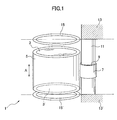
- FIG. 1 is a schematic diagram illustrating an autofocus system according to the present invention.
- the autofocus system of the present invention can be applied to a wide variety of electronic devices having a photograph function, such as a digital camera, a camera-equipped telephone, a camera-equipped PDA, a camera-equipped watch and a camera-equipped computer.
- a photograph function such as a digital camera, a camera-equipped telephone, a camera-equipped PDA, a camera-equipped watch and a camera-equipped computer.
- the autofocus system of the present invention is particularly well-suited to small, portable electronic devices.
- An important characteristic of the present invention is that pressure sensors which detect collision with camera lenses (focusing lenses) are disposed at positions where the camera lenses stop to improve the accuracy of measurement of the positions of the lenses.
- camera lenses 3 and 3' are supported on both ends of a cylindrical camera lens support 5.
- a ring-shaped slide member 7 is provided at the middle of the side face of the camera lens support 5.
- a support shaft 11 penetrates through a through hole 9 of the slide member.
- the camera lenses 3 and 3' are slid along the support shaft 11 in the direction indicated by the arrow A shown in Fig. 1, for example.
- the lenses are slid by a piezo actuator (not shown). That is, the piezo actuator is used as an actuator for moving lenses. However, control of the positions of lenses by the piezo actuator is inaccurate, as described above.
- mechanical stoppers 13 and 13' are provided at opposing positions at which the stoppers can collide with the camera lenses 3 and 3' moved by the piezo actuator. Further, in the vicinities of these stoppers 13 and 13', e.g. on these stoppers, thin pressure sensors 15 and 15' are fixed, respectively, so that the positions of the lenses can be measured with high accuracy.
- These pressure sensors 15 and 15' are not of special configuration, and ordinary, commercially available pressure sensors which are used in video game controllers as well can be used as the pressure sensors 15 and 15'. Therefore, the pressure sensors can be obtained at low cost.
- the autofocus system of the present invention can measure the positions of the camera lenses with high accuracy. For instance, as in the example illustrated in Fig. 1, when the stopper 13 is positioned at a macro position of the camera lens 3, i.e.
- the stopper 13' is positioned at an infinite position of the camera lens 3', i.e. a position for photographing a farther subject, it can be readily detected through the pressure detection whether the camera lens is present at the macro position, the infinite position or a position between the macro position and the infinite position. Accordingly, even if control of the positions of the lenses by the piezo actuator is somewhat inaccurate, the inaccuracy is compensated by the actions of these pressure sensors 15 and 15', whereby it can be securely detected whether the camera lens is present at the position of the stopper 13 or 13'. Therefore, according to the present invention, the positions of lenses can be defined accurately at at least two points and can be used for autofocusing or macrophotography. As described above, according to the constitution of the present invention, the piezo actuator can be used as an actuator for controlling the positions of lenses by adding the pressure sensors to a camera module.
- a method of counting time is also conceivable, in addition to the method of the present invention.
- a time counting method is not practical because the lens moving distance (time) of the piezo actuator is insecure and it takes long time to implement autofocusing.
- the piezo actuator as an actuator for controlling the positions of the lenses
- an autofocus system which can be applied even to small apparatuses can be provided.
- a reduction in the size of the system simplification of the structure of the system and reductions in cost and power consumption can be achieved.
- the present invention can be applied to a wide variety of relatively small apparatuses incorporating an autofocus system.
Landscapes
- Physics & Mathematics (AREA)
- General Physics & Mathematics (AREA)
- Optics & Photonics (AREA)
- Automatic Focus Adjustment (AREA)
- Lens Barrels (AREA)
- Focusing (AREA)
- Studio Devices (AREA)
Abstract
An autofocus system which can be applied even to small apparatuses is provided, and an improvement in accuracy of measurement of the positions of lenses when a piezo actuator is used to control the positions of the lenses is achieved. An autofocus system comprises a camera lens support, a piezo actuator, stoppers, and pressure sensors, wherein the camera lens support supports camera lenses, the piezo actuator moves the camera lens support for autofocusing, the stoppers prevent excessive movement of the camera lenses moved by the piezo actuator, and the pressure sensors are situated in the vicinities of the stoppers and detect collision with the camera lenses moved by the piezo actuator.
Description
- The present invention relates to an autofocus system, especially, to an autofocus system using a piezo actuator.
- Most of relatively large apparatuses such as a video camera are equipped with an autofocus system as a standard system. In recent years, an attempt to apply this autofocus system to relatively small apparatuses such as a camera-equipped cellular phone and a PDA has started. To implement autofocusing in the autofocus system, such a device as a stepping motor or a piezo actuator is generally used as a device that is currently available as an actuator for moving a camera lens.
- An advantage of using the stepping motor consists in accurate pulse control. In other words, the moving distance (moving distance per pulse) of a lens by the stepping motor is highly accurate. However, the stepping motor is forced to be a relatively large device (generally, its diameter is 6 to 8 mm and its length is 6 to 10 mm) because it requires driving parts such as a lead screw and gears, an electrical circuit and a sensor so as to move the lens. Further, it consumes a very large amount of power (generally, 150 mA or higher) due to mechanical driving thereof.
- Meanwhile, the piezo actuator (actuator using a piezoelectric element) has such advantages that it is smaller than the stepping motor and thin, has high impact resistance and consumes a small amount of power. However, the piezo actuator is also not used in small apparatuses such as a camera-equipped cellular phone at present. The reason consists in insecure pulse control of the piezo actuator. In other words, the moving distance of a lens by the piezo actuator is readily changed by an environmental change or a mechanical change (such as a change in load). Because of having such a problem, although the piezo actuator has been used for continuous focusing on a moving subject in an apparatus such as a video camera as disclosed in, e.g. Japanese Patent Application Laid-Open No. 97379/1991, it has never been used in cameras for still images which require highly accurate focusing. However, if there exists an absolute position sensor which can compensate control of the position of a lens when the piezo actuator is used, it is considered possible to use the piezo actuator in cameras for still images. However, in camera modules used in small apparatuses such as cellular phones, an autofocus system having such a sensor has not yet existed. Accordingly, it is considered inappropriate to use the piezo actuator in small apparatuses.
- Meanwhile, in the field of camera-equipped cellular phones, for example, an increase in resolution has been proceeding rapidly, and it has been increasingly required to implement higher-precision focusing. As a result, standard installation of autofocus system in camera-equipped cellular phones as well as video cameras is desired.
- An object of the present invention is to provide an autofocus system which can be applied even to small apparatuses. Another object of the present invention is to achieve an improvement in accuracy of measurement of the positions of lenses when a piezo actuator is used to control the positions of the lenses.
- The present invention makes a piezo actuator usable as an actuator for controlling the positions of lenses by adding pressure sensors to a camera module.
- An autofocus system of the present invention comprises:
- a camera lens support,
- a piezo actuator,
- stoppers, and
- pressure sensors,
- wherein
- the camera lens support supports a camera lens,
- the piezo actuator moves the camera lens support for autofocusing, the stoppers prevent excessive movement of the camera lenses moved by the piezo actuator, and
- the pressure sensors are situated in the vicinities of the stoppers and detect collision with the camera lenses moved by the piezo actuator.
- In the above autofocus system, the pressure sensors are disposed at a macro position and an infinite position and can detect whether the camera lens is present at the macro position, the infinite position or a position between the macro and infinite positions. The above autofocus system can be installed in a variety of portable electronic devices.
-
- Fig. 1 is a schematic diagram illustrating an autofocus system according to the present invention.
- An example of an autofocus system according to a suitable embodiment of the present invention will be described with reference to Fig. 1. This diagram is a schematic diagram illustrating an autofocus system according to the present invention. The autofocus system of the present invention can be applied to a wide variety of electronic devices having a photograph function, such as a digital camera, a camera-equipped telephone, a camera-equipped PDA, a camera-equipped watch and a camera-equipped computer. However, it is considered that the autofocus system of the present invention is particularly well-suited to small, portable electronic devices.
- An important characteristic of the present invention is that pressure sensors which detect collision with camera lenses (focusing lenses) are disposed at positions where the camera lenses stop to improve the accuracy of measurement of the positions of the lenses.
- As is obvious from Fig. 1,
camera lenses 3 and 3' are supported on both ends of a cylindricalcamera lens support 5. At the middle of the side face of thecamera lens support 5, a ring-shaped slide member 7 is provided. Asupport shaft 11 penetrates through a throughhole 9 of the slide member. Thecamera lenses 3 and 3' are slid along thesupport shaft 11 in the direction indicated by the arrow A shown in Fig. 1, for example. The lenses are slid by a piezo actuator (not shown). That is, the piezo actuator is used as an actuator for moving lenses. However, control of the positions of lenses by the piezo actuator is inaccurate, as described above. For this reason, in the present invention, especially for preventing excessive movement of the camera lenses,mechanical stoppers 13 and 13' are provided at opposing positions at which the stoppers can collide with thecamera lenses 3 and 3' moved by the piezo actuator. Further, in the vicinities of thesestoppers 13 and 13', e.g. on these stoppers,thin pressure sensors 15 and 15' are fixed, respectively, so that the positions of the lenses can be measured with high accuracy. Thesepressure sensors 15 and 15' are not of special configuration, and ordinary, commercially available pressure sensors which are used in video game controllers as well can be used as thepressure sensors 15 and 15'. Therefore, the pressure sensors can be obtained at low cost. - In the above constitution, even if the
camera lenses 3 and 3' are moved by the piezo actuator and collide with thestopper 13 or 13', no means for detecting whether thecamera lenses 3 and 3' are situated at the position of thestopper 13 or 13' has so far been available. However, in the present invention, when thecamera lenses 3 and 3' are moved by the piezo actuator and contact thepressure sensor 15 or 15', pressure produced by the contact is detected by the pressure sensor. By this pressure detection, the autofocus system of the present invention can measure the positions of the camera lenses with high accuracy. For instance, as in the example illustrated in Fig. 1, when thestopper 13 is positioned at a macro position of thecamera lens 3, i.e. a position for photographing a closer subject, and the stopper 13' is positioned at an infinite position of the camera lens 3', i.e. a position for photographing a farther subject, it can be readily detected through the pressure detection whether the camera lens is present at the macro position, the infinite position or a position between the macro position and the infinite position. Accordingly, even if control of the positions of the lenses by the piezo actuator is somewhat inaccurate, the inaccuracy is compensated by the actions of thesepressure sensors 15 and 15', whereby it can be securely detected whether the camera lens is present at the position of thestopper 13 or 13'. Therefore, according to the present invention, the positions of lenses can be defined accurately at at least two points and can be used for autofocusing or macrophotography. As described above, according to the constitution of the present invention, the piezo actuator can be used as an actuator for controlling the positions of lenses by adding the pressure sensors to a camera module. - As a method of measuring the position of a camera lens, a method of counting time is also conceivable, in addition to the method of the present invention. However, such a time counting method is not practical because the lens moving distance (time) of the piezo actuator is insecure and it takes long time to implement autofocusing.
- According to the above present invention, since the positions of lenses can be detected with high accuracy despite use of the piezo actuator as an actuator for controlling the positions of the lenses, an autofocus system which can be applied even to small apparatuses can be provided. Further, by use of the piezo actuator, a reduction in the size of the system, simplification of the structure of the system and reductions in cost and power consumption can be achieved. The present invention can be applied to a wide variety of relatively small apparatuses incorporating an autofocus system.
Claims (3)
- An autofocus system comprising:a camera lens support,a piezo actuator,stoppers, andpressure sensors,whereinthe camera lens support supports camera lenses,the piezo actuator moves the camera lens support for autofocusing,the stoppers prevent excessive movement of the camera lenses moved by the piezo actuator, andthe pressure sensors are situated in the vicinities of the stoppers and detect collision with the camera lenses moved by the piezo actuator.
- The autofocus system of 1, wherein the pressure sensors are disposed at a macro position and an infinite position and can detect whether the camera lens is present at the macro position, the infinite position or a position between the macro and infinite positions.
- A portable electronic device comprising the autofocus system of claim 1 or 2.
Applications Claiming Priority (1)
| Application Number | Priority Date | Filing Date | Title |
|---|---|---|---|
| PCT/JP2003/016193 WO2005059615A1 (en) | 2003-12-17 | 2003-12-17 | Automatic focusing device |
Publications (1)
| Publication Number | Publication Date |
|---|---|
| EP1696255A1 true EP1696255A1 (en) | 2006-08-30 |
Family
ID=34685702
Family Applications (1)
| Application Number | Title | Priority Date | Filing Date |
|---|---|---|---|
| EP03780859A Withdrawn EP1696255A1 (en) | 2003-12-17 | 2003-12-17 | Automatic focusing device |
Country Status (6)
| Country | Link |
|---|---|
| US (1) | US20070031135A1 (en) |
| EP (1) | EP1696255A1 (en) |
| JP (1) | JPWO2005059615A1 (en) |
| CN (1) | CN100412594C (en) |
| AU (1) | AU2003289405A1 (en) |
| WO (1) | WO2005059615A1 (en) |
Cited By (1)
| Publication number | Priority date | Publication date | Assignee | Title |
|---|---|---|---|---|
| US9716847B1 (en) | 2012-09-25 | 2017-07-25 | Google Inc. | Image capture device with angled image sensor |
Families Citing this family (10)
| Publication number | Priority date | Publication date | Assignee | Title |
|---|---|---|---|---|
| JP4679349B2 (en) * | 2005-11-22 | 2011-04-27 | Necカシオモバイルコミュニケーションズ株式会社 | Imaging apparatus and lens movement control method |
| JP2009151124A (en) * | 2007-12-20 | 2009-07-09 | Sharp Corp | Sensor module, electronic information device, autofocus control method, control program, and readable storage medium |
| JP5433991B2 (en) * | 2008-06-24 | 2014-03-05 | 株式会社ニコン | Vibration actuator, lens barrel and camera |
| CN101726820B (en) * | 2008-10-22 | 2013-04-24 | 鸿富锦精密工业(深圳)有限公司 | Wafer-level lens module |
| CN101738823B (en) * | 2008-11-25 | 2011-11-30 | 华晶科技股份有限公司 | Focus adjustment mechanism and camera device with the focus adjustment mechanism |
| CN103584831A (en) * | 2013-11-14 | 2014-02-19 | 南京航空航天大学 | Focusing-type endoscopic capsule and system |
| CN108650506A (en) * | 2018-08-17 | 2018-10-12 | 深圳市东旭发自动化有限公司 | Camera module testing device |
| CN112393680B (en) * | 2019-08-16 | 2022-09-30 | 深圳中科飞测科技股份有限公司 | Detection device, control method thereof, detection lens assembly and controller |
| US12422693B2 (en) * | 2020-11-10 | 2025-09-23 | Beijing Xiaomi Mobile Software Co., Ltd. | Optical imaging system, method for performing optical image stabilization |
| CN116699796B (en) * | 2023-08-07 | 2023-10-13 | 西安信飞特信息科技有限公司 | Lens and method capable of feeding back focal length position |
Family Cites Families (19)
| Publication number | Priority date | Publication date | Assignee | Title |
|---|---|---|---|---|
| US5239331A (en) * | 1985-12-11 | 1993-08-24 | Canon Kabushiki Kaisha | Brake device for motor in camera |
| JPS62166879A (en) * | 1986-01-16 | 1987-07-23 | Sumitomo Electric Ind Ltd | Culture device with automatic focusing mechanism for specimen visual inspection device |
| JP2776482B2 (en) * | 1988-08-23 | 1998-07-16 | 株式会社リコー | Lens control device |
| JP2625567B2 (en) * | 1990-07-03 | 1997-07-02 | キヤノン株式会社 | Drive |
| JP3277386B2 (en) * | 1992-06-26 | 2002-04-22 | ソニー株式会社 | Lens position control device |
| US5376785A (en) * | 1992-10-02 | 1994-12-27 | Chin; Philip K. | Optical displacement sensor utilizing optical diffusion |
| JP3334921B2 (en) * | 1992-12-28 | 2002-10-15 | キヤノン株式会社 | Optical equipment |
| JPH07288988A (en) * | 1994-04-12 | 1995-10-31 | Canon Inc | Mobile device |
| US5784653A (en) * | 1996-01-26 | 1998-07-21 | Asahi Kogaku Kogyo Kabushiki Kaisha | Electronically controlled camera |
| JPH11265212A (en) * | 1998-03-17 | 1999-09-28 | Minolta Co Ltd | Driving device |
| JP3661138B2 (en) * | 1998-04-04 | 2005-06-15 | 東京エレクトロン株式会社 | High-speed alignment mechanism |
| JP2000028895A (en) * | 1998-07-09 | 2000-01-28 | Minolta Co Ltd | Driving device |
| DE19927129C1 (en) * | 1999-06-15 | 2001-01-04 | Wolf Gmbh Richard | Focusing and focal width adjuster for video camera with zoom lens produces time window which is supplied to focusing circuit and zoom control circuit to provide vertical scanning gap of video signal |
| JP2002107612A (en) * | 2000-09-28 | 2002-04-10 | Minolta Co Ltd | Portable terminal and method for driving lens unit |
| JP2002303779A (en) * | 2001-04-04 | 2002-10-18 | Olympus Optical Co Ltd | Position controller for zoom lens |
| JP2002341227A (en) * | 2001-05-16 | 2002-11-27 | Matsushita Electric Ind Co Ltd | Lens barrel |
| JP2003280076A (en) * | 2002-03-20 | 2003-10-02 | Ricoh Co Ltd | Imaging equipment |
| JP4069681B2 (en) * | 2002-05-29 | 2008-04-02 | 京セラ株式会社 | Mobile terminal and notification method thereof |
| JP2004004326A (en) * | 2002-05-31 | 2004-01-08 | Fuji Photo Film Co Ltd | Lens driving mechanism |
-
2003
- 2003-12-17 EP EP03780859A patent/EP1696255A1/en not_active Withdrawn
- 2003-12-17 CN CNB2003801110210A patent/CN100412594C/en not_active Expired - Fee Related
- 2003-12-17 JP JP2005512199A patent/JPWO2005059615A1/en active Pending
- 2003-12-17 WO PCT/JP2003/016193 patent/WO2005059615A1/en not_active Ceased
- 2003-12-17 AU AU2003289405A patent/AU2003289405A1/en not_active Abandoned
-
2006
- 2006-06-19 US US11/455,893 patent/US20070031135A1/en not_active Abandoned
Non-Patent Citations (1)
| Title |
|---|
| See references of WO2005059615A1 * |
Cited By (1)
| Publication number | Priority date | Publication date | Assignee | Title |
|---|---|---|---|---|
| US9716847B1 (en) | 2012-09-25 | 2017-07-25 | Google Inc. | Image capture device with angled image sensor |
Also Published As
| Publication number | Publication date |
|---|---|
| JPWO2005059615A1 (en) | 2007-07-12 |
| CN1910490A (en) | 2007-02-07 |
| AU2003289405A1 (en) | 2005-07-05 |
| US20070031135A1 (en) | 2007-02-08 |
| WO2005059615A1 (en) | 2005-06-30 |
| CN100412594C (en) | 2008-08-20 |
Similar Documents
| Publication | Publication Date | Title |
|---|---|---|
| US8090252B1 (en) | Lens barrel assembly for a camera | |
| US8014091B2 (en) | Camera module | |
| KR101912277B1 (en) | Actuator driving apparatus and camera module including the same | |
| EP1696255A1 (en) | Automatic focusing device | |
| KR20060028648A (en) | Camera lens positioning device using shape memory alloy and camera using this positioning device | |
| KR20070005946A (en) | Device for detecting position of camera lens for mobile terminal | |
| CN103176331A (en) | Optical image stabilizer | |
| KR101859377B1 (en) | Actuator driving apparatus and camera module including the same | |
| EP1914592A1 (en) | Vibration reduction mechanism and optical device | |
| CN102123245A (en) | Optical device, control method thereof, and imaging device | |
| US20250028147A1 (en) | Driving mechanism | |
| US7425823B2 (en) | Position detecting device and method of adjusting position | |
| EP2075612A1 (en) | Lens position control apparatus, imaging apparatus, and control method | |
| KR20060102497A (en) | Lens drive mechanism, lens unit and imaging device | |
| US8031257B2 (en) | Zoom lens control apparatus and optical instrument | |
| US20110142433A1 (en) | Drop detection using lens position sensing of camera module | |
| EP2637054B1 (en) | Image pickup lens, image pickup apparatus, and lens controlling method | |
| US20090185285A1 (en) | Lens barrel and imaging device | |
| EP4134722A1 (en) | Sma wire driving structure and closed-loop control method therefor, and electronic device | |
| KR20180012839A (en) | Actuator driving apparatus and camera module including the same | |
| KR100713547B1 (en) | Displacement Sensor in Small Camera Module | |
| KR20210083788A (en) | Driver ic and actuator of camera module including the same | |
| KR20060097061A (en) | Auto focus | |
| JP7553205B2 (en) | Link device, camera module, and electronic device | |
| KR20180054542A (en) | Actuator driving apparatus and camera module including the same |
Legal Events
| Date | Code | Title | Description |
|---|---|---|---|
| PUAI | Public reference made under article 153(3) epc to a published international application that has entered the european phase |
Free format text: ORIGINAL CODE: 0009012 |
|
| 17P | Request for examination filed |
Effective date: 20060627 |
|
| AK | Designated contracting states |
Kind code of ref document: A1 Designated state(s): DE FI FR GB NL |
|
| DAX | Request for extension of the european patent (deleted) | ||
| RBV | Designated contracting states (corrected) |
Designated state(s): DE FI FR GB NL |
|
| STAA | Information on the status of an ep patent application or granted ep patent |
Free format text: STATUS: THE APPLICATION HAS BEEN WITHDRAWN |
|
| 18W | Application withdrawn |
Effective date: 20091012 |