EP1696143A2 - Double split bearing - Google Patents
Double split bearing Download PDFInfo
- Publication number
- EP1696143A2 EP1696143A2 EP06003737A EP06003737A EP1696143A2 EP 1696143 A2 EP1696143 A2 EP 1696143A2 EP 06003737 A EP06003737 A EP 06003737A EP 06003737 A EP06003737 A EP 06003737A EP 1696143 A2 EP1696143 A2 EP 1696143A2
- Authority
- EP
- European Patent Office
- Prior art keywords
- pieces
- outer race
- cage
- roller
- rollers
- Prior art date
- Legal status (The legal status is an assumption and is not a legal conclusion. Google has not performed a legal analysis and makes no representation as to the accuracy of the status listed.)
- Granted
Links
Images

Classifications
-
- F—MECHANICAL ENGINEERING; LIGHTING; HEATING; WEAPONS; BLASTING
- F16—ENGINEERING ELEMENTS AND UNITS; GENERAL MEASURES FOR PRODUCING AND MAINTAINING EFFECTIVE FUNCTIONING OF MACHINES OR INSTALLATIONS; THERMAL INSULATION IN GENERAL
- F16C—SHAFTS; FLEXIBLE SHAFTS; ELEMENTS OR CRANKSHAFT MECHANISMS; ROTARY BODIES OTHER THAN GEARING ELEMENTS; BEARINGS
- F16C33/00—Parts of bearings; Special methods for making bearings or parts thereof
- F16C33/30—Parts of ball or roller bearings
- F16C33/58—Raceways; Race rings
- F16C33/60—Raceways; Race rings divided or split, e.g. comprising two juxtaposed rings
-
- F—MECHANICAL ENGINEERING; LIGHTING; HEATING; WEAPONS; BLASTING
- F16—ENGINEERING ELEMENTS AND UNITS; GENERAL MEASURES FOR PRODUCING AND MAINTAINING EFFECTIVE FUNCTIONING OF MACHINES OR INSTALLATIONS; THERMAL INSULATION IN GENERAL
- F16C—SHAFTS; FLEXIBLE SHAFTS; ELEMENTS OR CRANKSHAFT MECHANISMS; ROTARY BODIES OTHER THAN GEARING ELEMENTS; BEARINGS
- F16C33/00—Parts of bearings; Special methods for making bearings or parts thereof
- F16C33/30—Parts of ball or roller bearings
- F16C33/46—Cages for rollers or needles
- F16C33/51—Cages for rollers or needles formed of unconnected members
- F16C33/513—Cages for rollers or needles formed of unconnected members formed of arcuate segments for carrying one or more rollers
- F16C33/516—Cages for rollers or needles formed of unconnected members formed of arcuate segments for carrying one or more rollers with two segments, e.g. double-split cages with two semicircular parts
-
- F—MECHANICAL ENGINEERING; LIGHTING; HEATING; WEAPONS; BLASTING
- F16—ENGINEERING ELEMENTS AND UNITS; GENERAL MEASURES FOR PRODUCING AND MAINTAINING EFFECTIVE FUNCTIONING OF MACHINES OR INSTALLATIONS; THERMAL INSULATION IN GENERAL
- F16C—SHAFTS; FLEXIBLE SHAFTS; ELEMENTS OR CRANKSHAFT MECHANISMS; ROTARY BODIES OTHER THAN GEARING ELEMENTS; BEARINGS
- F16C9/00—Bearings for crankshafts or connecting-rods; Attachment of connecting-rods
Definitions
- the present invention is related to a double split bearing that rotatably supports a crankshaft and a cam shaft of an engine, for example.
- the bearing is split into two pieces and is interposed between semicircle recess portions opposed to a cylinder block and a crankcase which are housing, and a support shaft portion of the crank shaft.
- the bearing is split into two pieces and is interposed between semicircle recess portions opposed to a cylinder block and a crankcase which are housing, and a support shaft portion of the crank shaft.
- a step (for example, several micro meters to several tens of micro meters) occurs at an inner surface (raceway surface) of the parting surfaces, which causes vibration and noise and crack which leads early breakage at the time rollers roll in accordance with rotation of the crank shaft.
- Japanese Examined Patent Publication S63-29129 proposes to provide a groove having V shape at the raceway surface of the split races over the entire length in an axial direction. Since the V shape groove has a chamfering effect, sharp edge is prevented to be formed even if the step is formed at the parting surfaces.
- Japanese Utility Publication H1-102514 proposes to form a flat relief surface at an outer surface portion of an inner race, so that a load of rollers becomes zero when the rollers roll on the split surfaces.
- an object of the present invention is to provide a double split bearing having a structure in which rollers do not contact a step portion which may occurs at parting surfaces of half outer race pieces constituting an outer race due to a displacement error in a radial direction of the half outer race pieces, thereby the occurrence of the vibration and noise and the breakage of the roller is eliminated and a long life period is realized.
- the double split bearing according to the present invention comprises:
- the rollers do not collide with the V shape groove provided at the parting surfaces of the half outer races, vibration and noise do not occur and the rollers are not damaged, thereby long life period can be realized.
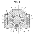
- Fig. 1 is an explanatory drawing showing a state in which a double split bearing according to an embodiment of the present invention is installed in a housing of an engine.
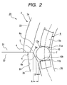
- Fig. 2 is an enlarged view showing a main portion of the double split bearing shown in Fig. 1. Incidentally, a part of drawing is emphasized to make the explanation of the present invention clear.
- a reference number 21 denotes a cylinder block that constitutes a housing 20 of an engine
- a reference number 22 denotes a crankcase coupled integrally with the cylinder block 21.
- Semicircle recess 23, 24 are formed on the cylinder block 21 and the crankcase 22, respectively, so as to be opposed to each other.
- a reference number 25 denotes a fixing bolt for fixing the cylinder block 21 to the crankcase 22.
- a reference numeral 26 is a support shaft of a crankshaft.
- a reference number 1 denotes a double split bearing according to the present invention which comprises an outer race 2, a cage 8 and rollers 7 held by the cage.
- the outer race includes half outer race pieces 3a, 3b which are respectively fitted to the recess portions 22, 24 of the cylinder block 21 and the crankcase 22, and have parting surfaces 4. When parting surfaces 4 of the half outer race pieces 3a, 3b are abutted to each other, the half outer race pieces 3a, 3b form a circle.
- the cage 8 includes half cage pieces 9a, 9b arranged at an outer periphery of the support shaft 26 of the crankshaft.
- the half outer race pieces 3a, 3b constituting the outer race 2 are formed with inclined surfaces 6, 6b which are expanded and inclined radially and outwardly toward the parting surfaces 4 from the inner surfaces thereof (raceway surfaces) over entire length in the axial direction.
- substantially V-shape groove 5 is formed by the opposed inclined surfaces 6a, 6b.
- the outer race pieces 3a, 3b are formed with high hardness (for example, Hv550 or higher) by induction quenching, carburizing treatment, nitriding treatment, etc.
- the cage 8 is provided with a plurality of pockets 10 for accommodating the roller 7 at a predetermined interval.
- Inner roller retainers 11a, 11b and outer roller retainers 12a, 12b for restricting movement of the rollers 7 are provided at the inner side and the outer side of both side walls of the pockets 10.
- the cylinder block is put up side down to orient the recess portion 23 upward, and the half outer race piece 3a and the half cage piece 9a are assembled into the recess portion 23, and the support shaft 26 of the crankshaft is put on it.
- the half cage piece 9b and the half outer race piece 3b are assembled to the support shaft 26, and the crankcase 22 is mounted thereon so that the recess portion 24 is fitted to the outer race 3b.
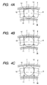
- Fig. 4A shows a state that the roller rolls while contacting with both raceway surfaces of the outer race 2 and the support shaft 26 of the crankshaft (or inner race) .
- the roller 7 is positioned at substantially center portion of the pocket 10.
- Fig. 4Bb shows a state that little clearance exists between the cage 8 and the outer race 2, and clearance exists between the cage 8 and the support shaft 26. In this state, the roller 7 moves toward the center portion and abuts against the support shaft 26.
- FIG. 4C shows a state that a clearance between the cage 8 and the support shaft 26 is small, and a clearance exists between the cage 8 and the outer race 2.
- the roller 7 is projected from the pocket 10 by centrifugal force generated by the rotation of the cage 8, and abutted against the raceway surface of the outer race 2.
- a projecting amount (displacement amount) of the roller 7 is restricted by the roller retainers 12.
- the roller retainers 12a, 12b restrict the projecting amount of the roller. That is, as shown in Fig. 2, the roller retainers 12a, 12b are formed at the outer periphery of the pockets 10 so as to satisfy condition A > B where A represent a height (step) from a start point of the inclined surfaces 6a, 6b provided at the parting surfaces 4 of the half outer race pieces 3a, 3b to an end point of the parting surfaces 4 and B represent a projecting amount of the roller 7 from the outer periphery of the cage 8.
- the double split bearing 1 according to the present invention supports the crankshaft of the engine.
- the present invention is not limited thereto, and can be applied to the bearing for supporting the rotating portion of other devices.
- the cage 8 is attached to the outer periphery of the support shaft 26 of the crankshaft.
- the inner race may be provided at an inner periphery of the cage 8.
Landscapes
- Engineering & Computer Science (AREA)
- General Engineering & Computer Science (AREA)
- Mechanical Engineering (AREA)
- Rolling Contact Bearings (AREA)
- Shafts, Cranks, Connecting Bars, And Related Bearings (AREA)
Abstract
Description
- The present invention is related to a double split bearing that rotatably supports a crankshaft and a cam shaft of an engine, for example.
- For example, as to a bearing for supporting a crankshaft of.an engine, due to the structural limitation, the bearing is split into two pieces and is interposed between semicircle recess portions opposed to a cylinder block and a crankcase which are housing, and a support shaft portion of the crank shaft.
To assemble such a double split bearing into the housing, since precision of the housing is not high as compared with the double split bearing, in the case that half outer race pieces which constitute an outer race of the double split bearing is to be assembled to the recessed portion of the housing, displacement error in the radial direction may occur at parting surfaces thereof. Thus, a step (for example, several micro meters to several tens of micro meters) occurs at an inner surface (raceway surface) of the parting surfaces, which causes vibration and noise and crack which leads early breakage at the time rollers roll in accordance with rotation of the crank shaft. - To solve the problem, Japanese Examined Patent Publication S63-29129 proposes to provide a groove having V shape at the raceway surface of the split races over the entire length in an axial direction. Since the V shape groove has a chamfering effect, sharp edge is prevented to be formed even if the step is formed at the parting surfaces.
- Japanese Utility Publication H1-102514 proposes to form a flat relief surface at an outer surface portion of an inner race, so that a load of rollers becomes zero when the rollers roll on the split surfaces.
- In the split bearing disclosed in S63-29129B, although the formation of the sharp edge is suppressed by forming the V shape groove on the raceway surface of the split races, since the V shape groove still exist on the raceway surface even if the formation of the sharp edge is suppressed, vibration and noise due to the rolling of the roller cannot sufficiently suppressed and the breakage of the roller cannot prevented.
- As to the double split bearing disclosed in JP1-102514U, although the measurement for the split surface of the inner race has been tanked, a measurement for the split surface of the outer race is not taken. Thus, if the step portion at the split surfaces occurs due to the displacement error of the half outer race pieces in the radial direction, life period of the bearing is shorten due to the occurrence of the vibration and noise and the breakage of the rollers.
- To solve the above problem, an object of the present invention is to provide a double split bearing having a structure in which rollers do not contact a step portion which may occurs at parting surfaces of half outer race pieces constituting an outer race due to a displacement error in a radial direction of the half outer race pieces, thereby the occurrence of the vibration and noise and the breakage of the roller is eliminated and a long life period is realized.
The double split bearing according to the present invention comprises: - a pair of half outer race pieces, each of which include a parting surface and includes an inclined surface that is radially and outwardly expanded from an inner periphery surface thereof toward the parting surface;
- a plurality of rollers arranged at the inner periphery surfaces of the half outer race pieces;
- a pair of half cage pieces arranged at the inner periphery surfaces of the half outer race pieces, each of which is provided with a plurality of pockets that accommodate the rollers and include roller retainers for restricting a displacement amount of the rollers in a radial direction,
- According to the double split bearing of the invention, since the rollers do not collide with the V shape groove provided at the parting surfaces of the half outer races, vibration and noise do not occur and the rollers are not damaged, thereby long life period can be realized.
-
- Fig. 1 is an explanatory drawing showing a state in which a double split bearing according to an embodiment of the present invention is installed in a housing of an engine.
- Fig. 2 is an enlarged view showing a main portion of the double split bearing shown in Fig. 1.
- Fig. 3 is an explanatory drawing showing an effect of the present invention.
- Fig. 4 is an explanatory drawing showing an effect of a general double split bearing.
- Fig. 1 is an explanatory drawing showing a state in which a double split bearing according to an embodiment of the present invention is installed in a housing of an engine. Fig. 2 is an enlarged view showing a main portion of the double split bearing shown in Fig. 1. Incidentally, a part of drawing is emphasized to make the explanation of the present invention clear.
- As shown in Figs. 1 and 2, a
reference number 21 denotes a cylinder block that constitutes ahousing 20 of an engine, areference number 22 denotes a crankcase coupled integrally with thecylinder block 21. Semicircle recess 23, 24 are formed on thecylinder block 21 and thecrankcase 22, respectively, so as to be opposed to each other. Areference number 25 denotes a fixing bolt for fixing thecylinder block 21 to thecrankcase 22. Areference numeral 26 is a support shaft of a crankshaft. - A reference number 1 denotes a double split bearing according to the present invention which comprises an
outer race 2, acage 8 androllers 7 held by the cage. The outer race includes halfouter race pieces recess portions cylinder block 21 and thecrankcase 22, and have partingsurfaces 4. When partingsurfaces 4 of the halfouter race pieces outer race pieces cage 8 includeshalf cage pieces support shaft 26 of the crankshaft. - As shown in Fig. 2, the half
outer race pieces outer race 2 are formed withinclined surfaces 6, 6b which are expanded and inclined radially and outwardly toward theparting surfaces 4 from the inner surfaces thereof (raceway surfaces) over entire length in the axial direction. When theparting surfaces 4 abutted to each other, substantially V-shape groove 5 is formed by the opposedinclined surfaces outer race pieces - The
cage 8 is provided with a plurality ofpockets 10 for accommodating theroller 7 at a predetermined interval.Inner roller retainers outer roller retainers rollers 7 are provided at the inner side and the outer side of both side walls of thepockets 10. - To assemble the double split bearing 1 into the
housing 20 and support thesupport shaft 26 of the crankshaft, firstly, the cylinder block is put up side down to orient therecess portion 23 upward, and the halfouter race piece 3a and thehalf cage piece 9a are assembled into therecess portion 23, and thesupport shaft 26 of the crankshaft is put on it. Next, thehalf cage piece 9b and the halfouter race piece 3b are assembled to thesupport shaft 26, and thecrankcase 22 is mounted thereon so that therecess portion 24 is fitted to theouter race 3b. - With this assembly, the
parting surfaces 4 of the upper and lower half outer race pieces are abutted to each other. However, if center portions of therecess portions cylinder block 21 and thecrankcase 22 are slightly displaced from each other, displacement error in the radial direction occurs at theparting surfaces 4 of the halfouter race pieces recess portions step portion 5a occurs between them.
In this state, as shown in Fig. 1, thecylinder block 21 and thecrankcase 22 are integrally fixed by screwing thefixing bolt 25. - Next, effect of the
general rollers 7 accommodated in thepockets 10 of thecage 8 will be described with reference to Figs. 4A to 4C.
Fig. 4A shows a state that the roller rolls while contacting with both raceway surfaces of theouter race 2 and thesupport shaft 26 of the crankshaft (or inner race) . In this state, theroller 7 is positioned at substantially center portion of thepocket 10. Fig. 4Bb shows a state that little clearance exists between thecage 8 and theouter race 2, and clearance exists between thecage 8 and thesupport shaft 26. In this state, theroller 7 moves toward the center portion and abuts against thesupport shaft 26. Fig. 4C shows a state that a clearance between thecage 8 and thesupport shaft 26 is small, and a clearance exists between thecage 8 and theouter race 2. In this state, theroller 7 is projected from thepocket 10 by centrifugal force generated by the rotation of thecage 8, and abutted against the raceway surface of theouter race 2. At this time, a projecting amount (displacement amount) of theroller 7 is restricted by theroller retainers 12. - As described above, clearances between the
cage 8 and theouter race 2 and between thecage 8 and thesupport shaft 26 always vary in response to the rotation of thesupport shaft 26, and therollers 7 move in the radial direction accordingly.
As shown in Fig. 3, when thesupport shaft 26 rotates in a direction of an arrow as shown in Fig. 1, thecage 8 attached thereto also rotates in the same direction. When therollers 7 that have contacted theouter race 2 and thesupport shaft 26 reach the V-shape groove 5 provide at theparting surfaces 4 of the halfouter race pieces cage 8 and theouter race 2 become sharply large, therollers 7 collide with thestep portion 5a of the V-shape groove 5. Therefore, as described above, the vibration and noise occur and therollers 7 are damaged. - According to the present invention, the
roller retainers roller retainers pockets 10 so as to satisfy condition A > B where A represent a height (step) from a start point of theinclined surfaces parting surfaces 4 of the halfouter race pieces parting surfaces 4 and B represent a projecting amount of theroller 7 from the outer periphery of thecage 8. - In the arrangement described above, as shown in Fig. 3, when the
support shaft 26 rotates in a direction of an arrow as shown in Fig. 1, thecage 8 attached thereto also rotates in the same direction. When theroller 7 that has rolled while contacting theouter race 2 and thesupport shaft 26 at the upstream side of the V-shape groove 5 rolls toward theV shape groove 5 and reach theinclined surface 6b, theroller 7 is projected by the centrifugal force since the clearance between theouter race 2 and thecage 8 becomes large. However, the projecting amount of the roller is restricted by theroller retainers roller 7 moves slight toward theinclined surface 6b and then is separated from theinclined surface 6b without collision with thestep 5a. Therefore, vibration and noise do not occur and the roller is not damaged. - As described above, it is described the case in which the double split bearing 1 according to the present invention supports the crankshaft of the engine. However, the present invention is not limited thereto, and can be applied to the bearing for supporting the rotating portion of other devices.
In the above embodiment, thecage 8 is attached to the outer periphery of thesupport shaft 26 of the crankshaft. However, the inner race may be provided at an inner periphery of thecage 8.
Claims (1)
- A double split bearing comprising:a pair of half outer race pieces, each of which include a parting surface and includes an inclined surface that is radially and outwardly expanded from an inner periphery surface thereof toward the parting surface;a plurality of rollers arranged at the inner periphery surfaces of the half outer race pieces;a pair of half cage pieces arranged at the inner periphery surfaces of the half outer race pieces, each of which is provided with a plurality of pockets that accommodate the rollers and include roller retainers for restricting a displacement amount of the rollers in a radial direction,wherein the roller retainers are formed at an outer periphery of the pockets so as to satisfy condition A > B where A represent a height from a start point of the inclined surfaces provided at the parting surfaces of the half outer races pieces to an end point of the parting surfaces and B represent a projecting amount of the roller from the outer periphery of the cage.
Applications Claiming Priority (1)
| Application Number | Priority Date | Filing Date | Title |
|---|---|---|---|
| JP2005049968A JP4507915B2 (en) | 2005-02-25 | 2005-02-25 | Split bearing |
Publications (3)
| Publication Number | Publication Date |
|---|---|
| EP1696143A2 true EP1696143A2 (en) | 2006-08-30 |
| EP1696143A3 EP1696143A3 (en) | 2008-10-15 |
| EP1696143B1 EP1696143B1 (en) | 2010-08-11 |
Family
ID=36337406
Family Applications (1)
| Application Number | Title | Priority Date | Filing Date |
|---|---|---|---|
| EP20060003737 Expired - Fee Related EP1696143B1 (en) | 2005-02-25 | 2006-02-23 | Double split bearing |
Country Status (3)
| Country | Link |
|---|---|
| EP (1) | EP1696143B1 (en) |
| JP (1) | JP4507915B2 (en) |
| DE (1) | DE602006016032D1 (en) |
Cited By (4)
| Publication number | Priority date | Publication date | Assignee | Title |
|---|---|---|---|---|
| US8136998B2 (en) | 2007-12-13 | 2012-03-20 | Jtekt Corporation | Bearing apparatus |
| US20150131935A1 (en) * | 2012-05-21 | 2015-05-14 | Ntn Corporation | Roller bearing and shaft support structure |
| US20150147015A1 (en) * | 2013-11-25 | 2015-05-28 | Jtekt Corporation | Split cage and roller bearing |
| CN108869550A (en) * | 2018-08-10 | 2018-11-23 | 镇江鑫可轴承有限公司 | A kind of combined retainer type roller bearing |
Families Citing this family (3)
| Publication number | Priority date | Publication date | Assignee | Title |
|---|---|---|---|---|
| JP2009144795A (en) * | 2007-12-13 | 2009-07-02 | Jtekt Corp | Bearing structure |
| JP2009144793A (en) * | 2007-12-13 | 2009-07-02 | Jtekt Corp | Bearing structure |
| JP5333718B2 (en) * | 2008-05-28 | 2013-11-06 | 横浜ゴム株式会社 | Pipe fitting |
Family Cites Families (9)
| Publication number | Priority date | Publication date | Assignee | Title |
|---|---|---|---|---|
| FR501092A (en) * | 1918-06-12 | 1920-04-01 | Skf Svenska Kullagerfab Ab | Improvements to ball bearings fitted with sectional raceways |
| JPS5563009A (en) * | 1978-11-02 | 1980-05-12 | Ntn Toyo Bearing Co Ltd | Divided bearing |
| JPS55149418A (en) * | 1979-04-28 | 1980-11-20 | Nachi Fujikoshi Corp | Split roller bearing |
| JPS5672924U (en) * | 1979-11-12 | 1981-06-15 | ||
| JPS5865318A (en) * | 1981-10-13 | 1983-04-19 | Sanshin Ind Co Ltd | Needle bearing |
| JPS5913123A (en) * | 1982-07-13 | 1984-01-23 | Michio Yoshikawa | Half-split rolling bearing |
| JPH01102514U (en) * | 1987-12-28 | 1989-07-11 | ||
| DE3920689A1 (en) * | 1989-06-21 | 1991-01-10 | Mannesmann Ag | ROLLER BEARING |
| DE20306899U1 (en) * | 2003-05-05 | 2004-09-09 | Ab Skf | Rolling bearing for wind power plant, for example, has segmented flange with run-on face which for each bearing segment in proximity of end faces assumes form of transition profile |
-
2005
- 2005-02-25 JP JP2005049968A patent/JP4507915B2/en not_active Expired - Fee Related
-
2006
- 2006-02-23 EP EP20060003737 patent/EP1696143B1/en not_active Expired - Fee Related
- 2006-02-23 DE DE200660016032 patent/DE602006016032D1/en not_active Expired - Lifetime
Cited By (8)
| Publication number | Priority date | Publication date | Assignee | Title |
|---|---|---|---|---|
| US8136998B2 (en) | 2007-12-13 | 2012-03-20 | Jtekt Corporation | Bearing apparatus |
| US20150131935A1 (en) * | 2012-05-21 | 2015-05-14 | Ntn Corporation | Roller bearing and shaft support structure |
| EP2853758A4 (en) * | 2012-05-21 | 2016-04-06 | Ntn Toyo Bearing Co Ltd | ROLLER BEARING AND TREE SUPPORT STRUCTURE |
| US9512881B2 (en) * | 2012-05-21 | 2016-12-06 | Ntn Corporation | Roller bearing and shaft support structure |
| US20150147015A1 (en) * | 2013-11-25 | 2015-05-28 | Jtekt Corporation | Split cage and roller bearing |
| US9194430B2 (en) * | 2013-11-25 | 2015-11-24 | Jtekt Corporation | Split cage and roller bearing |
| CN108869550A (en) * | 2018-08-10 | 2018-11-23 | 镇江鑫可轴承有限公司 | A kind of combined retainer type roller bearing |
| CN108869550B (en) * | 2018-08-10 | 2023-09-26 | 镇江鑫可轴承有限公司 | Combined retainer type roller bearing |
Also Published As
| Publication number | Publication date |
|---|---|
| JP2006234074A (en) | 2006-09-07 |
| EP1696143B1 (en) | 2010-08-11 |
| EP1696143A3 (en) | 2008-10-15 |
| DE602006016032D1 (en) | 2010-09-23 |
| JP4507915B2 (en) | 2010-07-21 |
Similar Documents
| Publication | Publication Date | Title |
|---|---|---|
| US20090126195A1 (en) | Roller bearing | |
| JP5303240B2 (en) | Rolling bearing and rotating shaft support structure | |
| WO2012099120A1 (en) | Roller bearing | |
| WO2009157155A1 (en) | Cylindrical roller bearing | |
| JP4790341B2 (en) | Needle roller bearing and bearing structure | |
| EP1696143B1 (en) | Double split bearing | |
| WO2011055630A1 (en) | Camshaft apparatus | |
| JP2019173919A (en) | Cage for self-aligning roller bearing | |
| JP2009014078A (en) | Needle roller bearing and crankshaft supporting structure | |
| JP2020070857A (en) | Slewing bearing | |
| JP2000320558A (en) | Synthetic resin cage for roller bearings | |
| JP2004301314A (en) | Rolling bearing | |
| JP2019183888A (en) | Bearing support structure of rotational shaft | |
| JP5499327B2 (en) | Rolling bearing | |
| JP5095630B2 (en) | Bearing race | |
| JPH09264156A (en) | Crankshaft supporting structure for 2-cycle engine | |
| JP2513590Y2 (en) | Double row spherical roller bearing | |
| JP4480639B2 (en) | Needle roller bearing and outer ring manufacturing method | |
| JP2587897Y2 (en) | Rolling bearing | |
| JP2020070814A (en) | Ball bearing | |
| JP5012265B2 (en) | Crankshaft support structure and crankshaft bearing | |
| JP2012154428A (en) | Split type rolling bearing | |
| JP4563885B2 (en) | Needle roller bearing | |
| JP5061796B2 (en) | Bearing structure | |
| JP2007010012A (en) | Needle roller bearing |
Legal Events
| Date | Code | Title | Description |
|---|---|---|---|
| PUAI | Public reference made under article 153(3) epc to a published international application that has entered the european phase |
Free format text: ORIGINAL CODE: 0009012 |
|
| AK | Designated contracting states |
Kind code of ref document: A2 Designated state(s): AT BE BG CH CY CZ DE DK EE ES FI FR GB GR HU IE IS IT LI LT LU LV MC NL PL PT RO SE SI SK TR |
|
| AX | Request for extension of the european patent |
Extension state: AL BA HR MK YU |
|
| PUAL | Search report despatched |
Free format text: ORIGINAL CODE: 0009013 |
|
| AK | Designated contracting states |
Kind code of ref document: A3 Designated state(s): AT BE BG CH CY CZ DE DK EE ES FI FR GB GR HU IE IS IT LI LT LU LV MC NL PL PT RO SE SI SK TR |
|
| AX | Request for extension of the european patent |
Extension state: AL BA HR MK YU |
|
| 17P | Request for examination filed |
Effective date: 20090108 |
|
| AKX | Designation fees paid |
Designated state(s): DE FR |
|
| GRAP | Despatch of communication of intention to grant a patent |
Free format text: ORIGINAL CODE: EPIDOSNIGR1 |
|
| GRAC | Information related to communication of intention to grant a patent modified |
Free format text: ORIGINAL CODE: EPIDOSCIGR1 |
|
| GRAS | Grant fee paid |
Free format text: ORIGINAL CODE: EPIDOSNIGR3 |
|
| GRAA | (expected) grant |
Free format text: ORIGINAL CODE: 0009210 |
|
| AK | Designated contracting states |
Kind code of ref document: B1 Designated state(s): DE FR |
|
| REF | Corresponds to: |
Ref document number: 602006016032 Country of ref document: DE Date of ref document: 20100923 Kind code of ref document: P |
|
| PLBE | No opposition filed within time limit |
Free format text: ORIGINAL CODE: 0009261 |
|
| STAA | Information on the status of an ep patent application or granted ep patent |
Free format text: STATUS: NO OPPOSITION FILED WITHIN TIME LIMIT |
|
| 26N | No opposition filed |
Effective date: 20110512 |
|
| REG | Reference to a national code |
Ref country code: DE Ref legal event code: R097 Ref document number: 602006016032 Country of ref document: DE Effective date: 20110512 |
|
| REG | Reference to a national code |
Ref country code: FR Ref legal event code: PLFP Year of fee payment: 10 |
|
| PGFP | Annual fee paid to national office [announced via postgrant information from national office to epo] |
Ref country code: DE Payment date: 20150218 Year of fee payment: 10 |
|
| PGFP | Annual fee paid to national office [announced via postgrant information from national office to epo] |
Ref country code: FR Payment date: 20150210 Year of fee payment: 10 |
|
| REG | Reference to a national code |
Ref country code: DE Ref legal event code: R119 Ref document number: 602006016032 Country of ref document: DE |
|
| REG | Reference to a national code |
Ref country code: FR Ref legal event code: ST Effective date: 20161028 |
|
| PG25 | Lapsed in a contracting state [announced via postgrant information from national office to epo] |
Ref country code: DE Free format text: LAPSE BECAUSE OF NON-PAYMENT OF DUE FEES Effective date: 20160901 Ref country code: FR Free format text: LAPSE BECAUSE OF NON-PAYMENT OF DUE FEES Effective date: 20160229 |