EP1696141A1 - Tethered retainer assembly - Google Patents
Tethered retainer assembly Download PDFInfo
- Publication number
- EP1696141A1 EP1696141A1 EP20060001166 EP06001166A EP1696141A1 EP 1696141 A1 EP1696141 A1 EP 1696141A1 EP 20060001166 EP20060001166 EP 20060001166 EP 06001166 A EP06001166 A EP 06001166A EP 1696141 A1 EP1696141 A1 EP 1696141A1
- Authority
- EP
- European Patent Office
- Prior art keywords
- retainer
- blocking element
- component
- tether
- Prior art date
- Legal status (The legal status is an assumption and is not a legal conclusion. Google has not performed a legal analysis and makes no representation as to the accuracy of the status listed.)
- Granted
Links
- 230000000903 blocking effect Effects 0.000 claims abstract description 60
- 238000005452 bending Methods 0.000 claims description 4
- 229920003023 plastic Polymers 0.000 claims description 4
- 239000004033 plastic Substances 0.000 claims description 4
- 230000000452 restraining effect Effects 0.000 claims description 2
- 238000003780 insertion Methods 0.000 abstract description 7
- 230000037431 insertion Effects 0.000 abstract description 7
- 230000014759 maintenance of location Effects 0.000 description 3
- 239000000463 material Substances 0.000 description 3
- 238000000429 assembly Methods 0.000 description 2
- 230000000712 assembly Effects 0.000 description 2
- 238000010276 construction Methods 0.000 description 2
- 238000013461 design Methods 0.000 description 2
- 238000013459 approach Methods 0.000 description 1
- 230000000295 complement effect Effects 0.000 description 1
- 238000000605 extraction Methods 0.000 description 1
- 238000000034 method Methods 0.000 description 1
- 238000012986 modification Methods 0.000 description 1
- 230000004048 modification Effects 0.000 description 1
- 230000000717 retained effect Effects 0.000 description 1
- 238000012552 review Methods 0.000 description 1
Images

Classifications
-
- F—MECHANICAL ENGINEERING; LIGHTING; HEATING; WEAPONS; BLASTING
- F16—ENGINEERING ELEMENTS AND UNITS; GENERAL MEASURES FOR PRODUCING AND MAINTAINING EFFECTIVE FUNCTIONING OF MACHINES OR INSTALLATIONS; THERMAL INSULATION IN GENERAL
- F16B—DEVICES FOR FASTENING OR SECURING CONSTRUCTIONAL ELEMENTS OR MACHINE PARTS TOGETHER, e.g. NAILS, BOLTS, CIRCLIPS, CLAMPS, CLIPS OR WEDGES; JOINTS OR JOINTING
- F16B41/00—Measures against loss of bolts, nuts, or pins; Measures against unauthorised operation of bolts, nuts or pins
- F16B41/002—Measures against loss of bolts, nuts or pins
-
- Y—GENERAL TAGGING OF NEW TECHNOLOGICAL DEVELOPMENTS; GENERAL TAGGING OF CROSS-SECTIONAL TECHNOLOGIES SPANNING OVER SEVERAL SECTIONS OF THE IPC; TECHNICAL SUBJECTS COVERED BY FORMER USPC CROSS-REFERENCE ART COLLECTIONS [XRACs] AND DIGESTS
- Y10—TECHNICAL SUBJECTS COVERED BY FORMER USPC
- Y10T—TECHNICAL SUBJECTS COVERED BY FORMER US CLASSIFICATION
- Y10T24/00—Buckles, buttons, clasps, etc.
- Y10T24/45—Separable-fastener or required component thereof [e.g., projection and cavity to complete interlock]
- Y10T24/45225—Separable-fastener or required component thereof [e.g., projection and cavity to complete interlock] including member having distinct formations and mating member selectively interlocking therewith
- Y10T24/45602—Receiving member includes either movable connection between interlocking components or variable configuration cavity
- Y10T24/45775—Receiving member includes either movable connection between interlocking components or variable configuration cavity having resiliently biased interlocking component or segment
- Y10T24/45812—Receiving member includes either movable connection between interlocking components or variable configuration cavity having resiliently biased interlocking component or segment and access opening with gapped perimeter for allowing movement of noninserted projection support therepast
-
- Y—GENERAL TAGGING OF NEW TECHNOLOGICAL DEVELOPMENTS; GENERAL TAGGING OF CROSS-SECTIONAL TECHNOLOGIES SPANNING OVER SEVERAL SECTIONS OF THE IPC; TECHNICAL SUBJECTS COVERED BY FORMER USPC CROSS-REFERENCE ART COLLECTIONS [XRACs] AND DIGESTS
- Y10—TECHNICAL SUBJECTS COVERED BY FORMER USPC
- Y10T—TECHNICAL SUBJECTS COVERED BY FORMER US CLASSIFICATION
- Y10T292/00—Closure fasteners
- Y10T292/68—Keepers
Landscapes
- Engineering & Computer Science (AREA)
- General Engineering & Computer Science (AREA)
- Mechanical Engineering (AREA)
- Clamps And Clips (AREA)
- Connection Of Plates (AREA)
- Insertion Pins And Rivets (AREA)
- Electrical Discharge Machining, Electrochemical Machining, And Combined Machining (AREA)
- Paper (AREA)
Abstract
Description
- The present invention relates generally to retainers for securing components and, more particularly, to retainers configured for holding a component of a fastener system.
- Simple fastening systems including a threaded male fastener component, such as a bolt, and a threaded female component, such as a nut, are used commonly in assemblies and constructions. Two or more items can be held together by providing aligned openings through the items and inserting and positioning the fastener system components from opposite sides of the items. A simple fastener system of this type is easy to use when both sides of the items being fastened together are readily accessible.
- In many assemblies, such as automobiles, appliances and the like, fastener systems are used in situations where only one side is easily accessed when the fastener is being secured. The opposite side may have been exposed at an early stage during the assembly, but becomes enclosed as assembly progresses. In these situations it is known to use a holding fixture, referred to as a "clip", which is affixed to the structure and is configured to hold one of the fastener system components, either the male component or the female component. With the first component securely positioned, the second component can be connected thereto even when the first component is no longer readily accessible. It is known also to use such clips to improve assembly efficiency by preassembling fastener components in proper position, and thereby eliminating the somewhat cumbersome step of aligning and securing several individual components for connection. However, it is often critical to overall assembly efficiency that the components are held securely and in a fixed, accurate position. Missing or misaligned fasteners or other components can significantly disrupt an assembly process.
- A simple design of a fastener retention clip includes an anchor structure by which the clip is attached to an item and a retainer structure for holding the fastener system component. It is known to use a channel or other limited access retainer structure having an opening through which the fastener component is inserted. It is known to close the opening after the fastener component is inserted so that the component is captured in the retainer structure. Closing the opening can be completed by attaching a closing piece, by deforming the entrance opening or structures near the entrance opening, or by other means. It is also known to use deflectable elements at the entrance opening that yield to the force of the fastener component being inserted and spring back to block the opening once the component is fully inserted into the retainer.
- To facilitate assembly efficiency, it is desirable to minimize steps. Hence, clip designs requiring additional steps for closing the retainer opening and capturing the component held therein can be less efficient. Clips having deflectable elements require fewer steps, but are not without drawbacks. Elements that are easy to deflect, thereby facilitating assembly with the fastener component to be held thereby, also can be easy to deflect or break if the captured component is pulled outward through the entrance opening. If the elements are made more rigid to provide increased resistance to pull out, the act of inserting the component to be captured can be difficult, requiring high insertion force.
- What is needed is a retainer for holding nuts, bolts and other components, which captures the component easily, yet holds it securely and resists withdrawal of the component from the retainer.
- The present invention provides a retainer with a blocking element at an entrance of the retainer, and a tether connected to the blocking element to resist pullout of a component held by the retainer.
- In one aspect thereof, the present invention provides a retainer for holding a component with a pocket configured for capturing at least a portion of the component therein. The pocket defines an entrance opening through which the component is inserted into the pocket. A blocking element has a fixed end and a distal end in the opening. The blocking element can be deflected to allow entrance to the pocket. A tether has an anchored end and a second end, the second end being connected to the blocking element near the distal end.
- In a further aspect thereof, the present invention provides a clip for holding a component, with an anchor for connecting the clip to an article and a retainer connected to the anchor. The retainer is configured for holding the component, and includes a pocket configured for capturing at least a portion of the component therein. The pocket defines an entrance opening through which the component is inserted into the pocket. A blocking element has a fixed end and a distal end in the opening. The blocking element is deflected to allow entrance to the pocket. A tether has an anchored end and a second end, the second end being connected to the blocking element near the distal end.
- In another aspect thereof, the present invention provides a retainer for holding a component. The retainer has a pocket with an entrance opening through which the component is inserted. A blocking element in the entrance opening is deflectable into the pocket. A tether restrains the blocking element from deflection in a direction away from the pocket.
- An advantage of the present invention is providing a retainer for fastener components that is easy to assembly with the fastener component, yet holds the fastener component securely, resisting pullout of the component.
- Another advantage of the present invention is providing a retainer that can be used for holding nuts, bolts or other items and is easy to assemble.
- Another advantage of the present invention is providing a retainer clip that holds an item securely yet can be manufactured inexpensively from plastic and other inexpensive materials.
- Other features and advantages of the invention will become apparent to those skilled in the art upon review of the following detailed description, claims and drawings in which like numerals are used to designate like features.
- Fig. 1 is a plan view of a clip having a tethered retainer assembly in accordance with the present invention;
- Fig. 2 a cross-sectional view of the tethered retainer shown in Fig. 1;
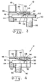
- Fig. 3 is a fragmentary cross-sectional view similar to that of Fig. 2, but illustrating a fastener component being inserted into the retainer; and
- Fig. 4 is a fragmentary cross-sectional view similar to Fig. 3, but illustrating the fastener component fully inserted into the retainer.
- Before the embodiments of the invention are explained in detail, it is to be understood that the invention is not limited in its application to the details of construction and the arrangements of the components set forth in the following description or illustrated in the drawings. The invention is capable of other embodiments and of being practiced or being carried out in various ways. Also, it is understood that the phraseology and terminology used herein are for the purpose of description and should not be regarded as limiting. The use herein of "including", "comprising" and variations thereof is meant to encompass the items listed thereafter and equivalents thereof, as well as additional items and equivalents thereof.
- Referring now more specifically to the drawings and to Figs. 1 and 2 in particular,
numeral 10 designates a clip having aretainer 12 in accordance with the present invention.Clip 10 further includes ananchor portion 14 by whichclip 10 can be secured to an item or article.Clip 10, includingretainer 12 andanchor portion 14 is a monolithic body of suitable material. Plastics commonly are suitable for use asclip 10, although other materials also can be used for at least parts ofclip 10. -
Anchor portion 14 as illustrated in Fig. 1 is merely one suitable configuration. Those skilled in the art will readily understand thatanchor portion 14 can be of any suitable configuration for installing and securingclip 10 to an article or item on which it is used. Thus,clip 10 can include a variety ofwalls 16 defining snap fit locking structures for surrounding or being inserted into portions of the item or article onto whichclip 10 is installed. Further,anchor portion 14 can define holes (not shown) or other suitable structure for receiving other fasteners to secureclip 10 in the desired position. Still other interference or snapfit configurations foranchor portion 14 can be used to secureclip 10 in a desired location and orientation. -
Retainer 12 defines apocket 18 includingchannels back 24 and anentrance opening 26. In the embodiment ofretainer 12 illustrated, entrance opening 26 is disposed at ends ofchannels open space 28 frompocket 18 is provided betweenchannels retainer 12 can be secured inpocket 12, with a portion of the component projecting frompocket 12, throughopen space 28. - A blocking
element 30 is provided atentrance opening 26 and includes afixed end 32 and adistal end 34 having anoutermost tip 36. Blockingelement 30 is deflectable in a direction inwardly towardpocket 18. - A
tether 40 includes ananchored end 42 and asecond end 44 affixed to blockingelement 30. As will be described in further detail,tether 40 is configured and arranged with respect to blockingelement 30 to restrain blockingelement 30 from deflection in a direction away frompocket 18 and to cooperate with deflection of blockingelement 30 in a direction into or towardpocket 18. - As thus far described,
retainer 12 is configured for receiving and retaining abolt 50 having ahead 52, ashank 54 and threads 56 (Figs. 3 & 4).Head 52 is held inpocket 18, withshank 54 projecting throughopen space 28 such that at least a portion ofthread 56 is exposed for attachment with a complementary female fastener component (not shown). - Accordingly,
channels pocket 18, as can be seen most clearly in Fig. 1.Channels head 52 ofbolt 50 therein, with minimal free lateral movement ofhead 52 allowed. Back 24 defines a lip for engaging the end ofhead 52 opposite the end nearestentrance opening 26.Head 52 is thereby securely retained inpocket 18 withshank 54 projecting outwardly throughopening 28 and exposingthreads 56 thereon. To facilitate insertion ofhead 52, as illustrated in the drawings, the widths and depths ofchannels head 52 is easily aligned withchannels bolt 50 withclip 10. -
Tether 40, and specificallysecond end 44 thereof is joined to blockingelement 30 slightly inwardly ondistal end 34, thereby leavingoutermost tip 36 exposed. As illustrated in Fig. 4, withhead 52 fully inserted intopocket 18,outermost tip 36 is held against the side ofhead 52 opposite the side disposed against back 24. Thus,head 52 is securely held not only betweenchannels outermost tip 36 on two other opposite sides thereof. Accordingly,head 52 is held inpocket 18 in substantially fixed position. -
Tether 40, and specifically anchor end 42 thereof is secured to apanel 58 inwardly withinpocket 18 from entrance opening 26 relative to blockingelement 30 and specifically fixedend 32 of blockingelement 30. Thus, as illustrated in Fig. 3, asbolt 50 is being inserted intopocket 18,head 52 is pushed against and deflects blockingelement 30 andtether 40 away from opening 28, thereby allowinghead 52 to be pushed intopocket 18. Blockingelement 30 andtether 40 are flattened towardpanel 58, andoutermost tip 36 slides all an end surface ofhead 52 asbolt 50 is inserted intopocket 18. Ashead 52 approaches back 24, an outermost edge thereof has passedoutermost tip 36 of blockingelement 30, and blockingelement 30 rebounds as shown in Fig. 4. In the rebounded position of blockingelement 30,outermost tip 36 is provided on a side ofhead 52 and the juncture of blockingelement 30 andtether 40 engages an outer end edge ofhead 52. Thus,head 52 is held also biased towardsopening 28. - Blocking
element 30 is easily deflected along withtether 40 upon insertion ofbolt 50. However, afterhead 52 is fully inserted inpocket 18 and blockingelement 30 has rebounded, if withdrawal force is applied to bolt 50 in a direction attempting to pullhead 52 frompocket 18,tether 40 securesdistal end 34 such that it is not easily pulled outwardly relative toentrance opening 26. Deflection of blockingelement 30 in a direction away frompocket 18places tether 40 in tension, restraining blockingelement 30 from outward deflection. Accordingly, while insertion force necessary to deflect blockingelement 30 inwardly is minimal, the withdrawal or extraction force necessary to pullbolt 50 frompocket 18 is significantly higher. Accordingly, assembly ofbolt 50 inretainer 12 is easily performed, yetretainer 12 provides a strong, secure retention ofbolt 50 inclip 10. - To further facilitate insertion of
bolt 50 intopocket 18, a flex zone orbreakpoint 60 can be provided such as near the juncture of blockingelement 30 andtether 40.Breakpoint 60 predisposes bending at a desired location in response to the compressive forces applied ashead 52 is inserted, further reducing force required to inserthead 52. However,breakpoint 60 is not of significance in responses to forces in tension that occur ifbolt 50 is forced outwardly relative topocket 18. Accordingly, the use ofbreakpoint 60 can increase the difference between the force required to installbolt 50 inpocket 18, and the resistance applied by blockingelement 30 to withdrawal ofbolt 50. - It should be understood that although
retainer 12 is illustrated holdingbolt 50,retainer 12 also can be configured as necessary to secure and hold other things. Accordingly,retainer 12 in accordance with the present invention can be configured to hold a nut, washer or other item, article or component. The size, shape andstructures forming pocket 18 can be selected to hold the particular component desired. A variety of configurations forretainer 12 andpocket 18 can utilize features of the present invention, including blockingelement 30 at anentrance opening 26 andtether 40 to provide improved retention of the item, article or component held in the pocket. - Further, blocking
element 30 can take a variety of configurations and shapes as necessary to properly close entrance opening 26 after the item, article or component has been inserted intopocket 18. Further, while a single, substantiallyU-shaped blocking element 30 is shown in the exemplary embodiment, other shapes and configurations can be used. Two or more blocking elements also can be used. When two or more blocking elements are used,individual tethers 40 can be provided for each blocking element. - Variations and modifications of the foregoing are within the scope of the present invention. It is understood that the invention disclosed and defined herein extends to all alternative combinations of two or more of the individual features mentioned or evident from the text and/or drawings. All of these different combinations constitute various alternative aspects of the present invention. The embodiments described herein explain the best modes known for practicing the invention and will enable others skilled in the art to utilize the invention. The claims are to be construed to include alternative embodiments to the extent permitted by the prior art.
- Various features of the invention are set forth in the following claims.
Claims (20)
- A retainer for holding a component, said retainer comprising:a pocket configured for capturing at least a portion of the component therein, said pocket defining an entrance opening through which the component is inserted into the pocket;a blocking element having a fixed end and a distal end in said opening, said blocking element being deflected to allow entrance to said pocket; anda tether having an anchored end and a second end, said second end being connected to said blocking element near said distal end.
- The retainer of claim 1, said anchored end of said tether being inwardly in said pocket from said entrance opening relative to said fixed end of said blocking element.
- The retainer of claim 1, said blocking element having an outermost tip, and said tether being connected to said blocking element in spaced relation to said outermost tip.
- The retainer of claim 3, said anchored end of said tether being inwardly in said pocket from said entrance opening relative to said fixed end of said blocking element.
- The retainer of claim 4, including a breakpoint in said tether for directed bending in response to deflection of said blocking element.
- The retainer of claim 4, said pocket having opposed channels in spaced relation, and said entrance opening being at ends of said channels.
- The retainer of claim 6, said blocking element being substantially centrally located between said channels.
- The retainer of claim 7, said retainer being made of plastic.
- The retainer of claim 1, said pocket having opposed channels in spaced relation, and said entrance opening being at ends of said channels.
- The retainer of claim 1, including a breakpoint in said tether for directed bending in response to deflection of said blocking element.
- A clip for holding a component, said clip comprising:an anchor portion configured for connecting said clip to an article;a retainer connected to said anchor portion, said retainer being configured for holding the component, said retainer including:a pocket configured for capturing at least a portion of the component therein, said pocket defining an entrance opening through which the component is inserted into the pocket;a blocking element having a fixed end and a distal end in said opening, said blocking element being deflected to allow entrance to said pocket; anda tether having an anchored end and a second end, said second end being connected to said blocking element near said distal end.
- The clip of claim 11, said anchor end of said tether being inwardly in said pocket from said entrance opening relative to said fixed end of said blocking element.
- The clip of claim 11, said blocking element having an outermost tip and said tether being connected to said blocking element away from said outermost tip.
- The clip of claim 11, including a breakpoint in said tether for directed bending in response to deflection of said blocking element.
- The clip of claim 11, said anchor and said retainer being portions of a monolithic body of plastic.
- The clip of claim 11, said retainer defining opposed channels in spaced relation and said entrance opening being at ends of said channels.
- A retainer for holding a component, said retainer comprising:a pocket having an entrance opening through which the component is inserted;a blocking element in said entrance opening deflectable into said pocket; anda tether restraining said blocking element from deflection in a direction away from said pocket.
- The retainer of claim 17, said pocket having a back opposite said opening and opposed channels extending from said opening to said back.
- The retainer of claim 18, said channels being deeper at said opening than at said back.
- The retainer of claim 18, said channels being wider at said opening than at said back.
Applications Claiming Priority (1)
| Application Number | Priority Date | Filing Date | Title |
|---|---|---|---|
| US11/067,195 US7189043B2 (en) | 2005-02-25 | 2005-02-25 | Tethered retainer assembly |
Publications (2)
| Publication Number | Publication Date |
|---|---|
| EP1696141A1 true EP1696141A1 (en) | 2006-08-30 |
| EP1696141B1 EP1696141B1 (en) | 2007-07-04 |
Family
ID=36499328
Family Applications (1)
| Application Number | Title | Priority Date | Filing Date |
|---|---|---|---|
| EP20060001166 Not-in-force EP1696141B1 (en) | 2005-02-25 | 2006-01-20 | Tethered retainer assembly |
Country Status (6)
| Country | Link |
|---|---|
| US (1) | US7189043B2 (en) |
| EP (1) | EP1696141B1 (en) |
| JP (1) | JP5095947B2 (en) |
| CN (1) | CN100476220C (en) |
| AT (1) | ATE366376T1 (en) |
| DE (1) | DE602006000032T2 (en) |
Cited By (1)
| Publication number | Priority date | Publication date | Assignee | Title |
|---|---|---|---|---|
| CN102910375A (en) * | 2011-08-05 | 2013-02-06 | 永硕联合国际股份有限公司 | Display packing set |
Families Citing this family (13)
| Publication number | Priority date | Publication date | Assignee | Title |
|---|---|---|---|---|
| DE102004006204B3 (en) * | 2004-02-09 | 2005-09-22 | Hilti Ag | carrier connection |
| US20070107174A1 (en) * | 2005-11-17 | 2007-05-17 | Faurecia Interior Systems U.S.A., Inc. | Methods and apparatus for fastening panels |
| US7784857B2 (en) * | 2007-01-29 | 2010-08-31 | Toyota Motor Engineering & Manufacturing North America, Inc. | Fastener assembly |
| US8480341B2 (en) * | 2008-03-05 | 2013-07-09 | Lockheed Martin Corporation | Nut retainer cage |
| US7648319B1 (en) * | 2008-11-12 | 2010-01-19 | Orlando Ochoa | Clip nut fastener |
| JP5205444B2 (en) * | 2010-12-09 | 2013-06-05 | 株式会社ホンダアクセス | Exterior product mounting method |
| TWI417032B (en) * | 2011-03-25 | 2013-11-21 | Wistron Corp | Fixing mechanism for fixing a component |
| WO2013112166A2 (en) * | 2012-01-26 | 2013-08-01 | Empire Technology Development Llc | Sprung latch fastener |
| JP6161873B2 (en) * | 2012-04-10 | 2017-07-12 | 株式会社アルファ | Vehicle handle device |
| CN102852915A (en) * | 2012-07-31 | 2013-01-02 | 苏州柏德纳科技有限公司 | Part for bending mounting plate |
| EP3219995B1 (en) | 2016-03-18 | 2019-01-02 | International Automotive Components Group North America, Inc. | Panel fastening system |
| CN112449522A (en) * | 2019-09-05 | 2021-03-05 | 英业达科技有限公司 | Fixing frame |
| EP3904705A1 (en) * | 2020-05-01 | 2021-11-03 | HellermannTyton s.a.s. | Holder for insert and assembly comprising the holder and insert |
Citations (4)
| Publication number | Priority date | Publication date | Assignee | Title |
|---|---|---|---|---|
| US5851097A (en) * | 1997-06-03 | 1998-12-22 | Illinois Tool Works Inc. | Article with tethered prong fastener |
| DE19737159A1 (en) * | 1997-08-26 | 1999-03-04 | Ejot Kunststofftech Gmbh | Plastics holder for mounting pipes on objects |
| EP1363030A2 (en) * | 2002-05-15 | 2003-11-19 | Tyco Electronics AMP GmbH | Holder for a securing element |
| DE10259976A1 (en) * | 2002-12-19 | 2004-07-15 | Daimlerchrysler Ag | Holder for locating of screw in through-hole has sleeve with spring arms located on one end face, and sleeve on this end face has radial projections as contact face for head of screw in held position |
Family Cites Families (15)
| Publication number | Priority date | Publication date | Assignee | Title |
|---|---|---|---|---|
| US2986791A (en) * | 1958-04-07 | 1961-06-06 | Mary A Strehlein | Fastener |
| US4138151A (en) * | 1976-07-30 | 1979-02-06 | Olympus Optical Company Limited | Detent device for locking the lid of a cassette receiving compartment of a tape recorder |
| DE8013284U1 (en) * | 1980-05-16 | 1980-10-02 | Fa. A. Raymond, 7850 Loerrach | Fastening clamp for attaching door panel clips or the like. on unperforated cover plates made of hard fiber |
| JPS633967Y2 (en) * | 1981-01-12 | 1988-02-01 | ||
| US4436201A (en) * | 1981-11-11 | 1984-03-13 | Victor Company Of Japan Limited | Disc cartridge having a detachable lid |
| US4550230A (en) * | 1982-10-18 | 1985-10-29 | International Jensen Incorporated | Speaker grille with snap-in fastener system |
| JPH0238708A (en) * | 1988-07-29 | 1990-02-08 | Nifco Inc | Nut-type plastic fastener |
| US5201858A (en) * | 1992-08-07 | 1993-04-13 | Otrusina Edward C | Quick-release connector |
| US5598994A (en) * | 1995-06-29 | 1997-02-04 | Panduit Corp. | Stud engaging device |
| USD380667S (en) * | 1995-09-08 | 1997-07-08 | Nifco Inc. | Clip for attaching a material to a panel |
| JPH09296815A (en) * | 1996-04-30 | 1997-11-18 | Yazaki Corp | Resin molding with nut storage part |
| US5816762A (en) * | 1996-07-09 | 1998-10-06 | Illinois Tool Works Inc. | Stud clip having different insertion/withdrawal forces |
| US6719337B1 (en) * | 2000-11-03 | 2004-04-13 | Southco, Inc. | Push-push latch |
| JP2003329016A (en) * | 2002-05-13 | 2003-11-19 | Ryosei Electro-Circuit Systems Ltd | Connection mechanism |
| US6796760B1 (en) * | 2003-03-21 | 2004-09-28 | Intier Automotive Inc. | Retention structure for a fastener |
-
2005
- 2005-02-25 US US11/067,195 patent/US7189043B2/en active Active
-
2006
- 2006-01-20 AT AT06001166T patent/ATE366376T1/en not_active IP Right Cessation
- 2006-01-20 EP EP20060001166 patent/EP1696141B1/en not_active Not-in-force
- 2006-01-20 DE DE200660000032 patent/DE602006000032T2/en not_active Expired - Fee Related
- 2006-02-17 CN CNB2006100083476A patent/CN100476220C/en not_active Expired - Fee Related
- 2006-02-20 JP JP2006042624A patent/JP5095947B2/en not_active Expired - Fee Related
Patent Citations (4)
| Publication number | Priority date | Publication date | Assignee | Title |
|---|---|---|---|---|
| US5851097A (en) * | 1997-06-03 | 1998-12-22 | Illinois Tool Works Inc. | Article with tethered prong fastener |
| DE19737159A1 (en) * | 1997-08-26 | 1999-03-04 | Ejot Kunststofftech Gmbh | Plastics holder for mounting pipes on objects |
| EP1363030A2 (en) * | 2002-05-15 | 2003-11-19 | Tyco Electronics AMP GmbH | Holder for a securing element |
| DE10259976A1 (en) * | 2002-12-19 | 2004-07-15 | Daimlerchrysler Ag | Holder for locating of screw in through-hole has sleeve with spring arms located on one end face, and sleeve on this end face has radial projections as contact face for head of screw in held position |
Cited By (1)
| Publication number | Priority date | Publication date | Assignee | Title |
|---|---|---|---|---|
| CN102910375A (en) * | 2011-08-05 | 2013-02-06 | 永硕联合国际股份有限公司 | Display packing set |
Also Published As
| Publication number | Publication date |
|---|---|
| CN1831344A (en) | 2006-09-13 |
| JP5095947B2 (en) | 2012-12-12 |
| EP1696141B1 (en) | 2007-07-04 |
| DE602006000032T2 (en) | 2008-03-13 |
| CN100476220C (en) | 2009-04-08 |
| JP2006234166A (en) | 2006-09-07 |
| DE602006000032D1 (en) | 2007-08-16 |
| US7189043B2 (en) | 2007-03-13 |
| ATE366376T1 (en) | 2007-07-15 |
| US20060193710A1 (en) | 2006-08-31 |
Similar Documents
| Publication | Publication Date | Title |
|---|---|---|
| EP1696141B1 (en) | Tethered retainer assembly | |
| US7549830B2 (en) | Serviceable w-base fastener | |
| EP1957323B1 (en) | Fastener | |
| US8613414B2 (en) | Fastening clip and associated fastener | |
| US7219400B2 (en) | Clip and airbag body installation structure | |
| US6652206B2 (en) | Self-locking rivet fastener | |
| EP1155918A2 (en) | Molding fastening assembly | |
| US6176660B1 (en) | Releasable fastener with lateral stabilizing brace members and latch legs carrying fastener insertion guide | |
| US20080181748A1 (en) | Fastener For Application to a Threaded Stud | |
| KR20080110641A (en) | Turnlock fastener | |
| US20170114809A1 (en) | Self-locking edge clip fastener | |
| US7188815B2 (en) | Fastener with tethered members | |
| JP2008530479A (en) | Connecting device | |
| US20110219588A1 (en) | Attachment structure of clip and mounting-subject member | |
| US20060099049A1 (en) | Fastener/stud retainer | |
| US7134170B2 (en) | Plastic retaining clip for rib attachment | |
| KR20190039711A (en) | Rivet fastener assembly | |
| US8622680B1 (en) | Grommet | |
| GB2082668A (en) | Two part fastener | |
| KR101455203B1 (en) | Undetachable plastic anchor | |
| US20030159255A1 (en) | Clamp retention device | |
| CN112664523B (en) | Quick release fastening device retaining clip, quick release fastening device and assembly connection with the quick release fastening device | |
| US20050071959A1 (en) | Tether clip | |
| EP1484513B1 (en) | Resilient fastener with means for preventing rotation | |
| JP2010052731A (en) | Fastener for fixing arrester strap of airbag device |
Legal Events
| Date | Code | Title | Description |
|---|---|---|---|
| PUAI | Public reference made under article 153(3) epc to a published international application that has entered the european phase |
Free format text: ORIGINAL CODE: 0009012 |
|
| 17P | Request for examination filed |
Effective date: 20060120 |
|
| AK | Designated contracting states |
Kind code of ref document: A1 Designated state(s): AT BE BG CH CY CZ DE DK EE ES FI FR GB GR HU IE IS IT LI LT LU LV MC NL PL PT RO SE SI SK TR |
|
| AX | Request for extension of the european patent |
Extension state: AL BA HR MK YU |
|
| 17Q | First examination report despatched |
Effective date: 20061016 |
|
| GRAP | Despatch of communication of intention to grant a patent |
Free format text: ORIGINAL CODE: EPIDOSNIGR1 |
|
| GRAS | Grant fee paid |
Free format text: ORIGINAL CODE: EPIDOSNIGR3 |
|
| AKX | Designation fees paid |
Designated state(s): AT BE BG CH CY CZ DE DK EE ES FI FR GB GR HU IE IS IT LI LT LU LV MC NL PL PT RO SE SI SK TR |
|
| GRAA | (expected) grant |
Free format text: ORIGINAL CODE: 0009210 |
|
| AK | Designated contracting states |
Kind code of ref document: B1 Designated state(s): AT BE BG CH CY CZ DE DK EE ES FI FR GB GR HU IE IS IT LI LT LU LV MC NL PL PT RO SE SI SK TR |
|
| REG | Reference to a national code |
Ref country code: GB Ref legal event code: FG4D |
|
| REG | Reference to a national code |
Ref country code: CH Ref legal event code: EP |
|
| REG | Reference to a national code |
Ref country code: IE Ref legal event code: FG4D |
|
| REF | Corresponds to: |
Ref document number: 602006000032 Country of ref document: DE Date of ref document: 20070816 Kind code of ref document: P |
|
| NLV1 | Nl: lapsed or annulled due to failure to fulfill the requirements of art. 29p and 29m of the patents act | ||
| REG | Reference to a national code |
Ref country code: CH Ref legal event code: PL |
|
| PG25 | Lapsed in a contracting state [announced via postgrant information from national office to epo] |
Ref country code: NL Free format text: LAPSE BECAUSE OF FAILURE TO SUBMIT A TRANSLATION OF THE DESCRIPTION OR TO PAY THE FEE WITHIN THE PRESCRIBED TIME-LIMIT Effective date: 20070704 Ref country code: BG Free format text: LAPSE BECAUSE OF FAILURE TO SUBMIT A TRANSLATION OF THE DESCRIPTION OR TO PAY THE FEE WITHIN THE PRESCRIBED TIME-LIMIT Effective date: 20071004 Ref country code: ES Free format text: LAPSE BECAUSE OF FAILURE TO SUBMIT A TRANSLATION OF THE DESCRIPTION OR TO PAY THE FEE WITHIN THE PRESCRIBED TIME-LIMIT Effective date: 20071015 Ref country code: LT Free format text: LAPSE BECAUSE OF FAILURE TO SUBMIT A TRANSLATION OF THE DESCRIPTION OR TO PAY THE FEE WITHIN THE PRESCRIBED TIME-LIMIT Effective date: 20070704 Ref country code: PT Free format text: LAPSE BECAUSE OF FAILURE TO SUBMIT A TRANSLATION OF THE DESCRIPTION OR TO PAY THE FEE WITHIN THE PRESCRIBED TIME-LIMIT Effective date: 20071204 Ref country code: IS Free format text: LAPSE BECAUSE OF FAILURE TO SUBMIT A TRANSLATION OF THE DESCRIPTION OR TO PAY THE FEE WITHIN THE PRESCRIBED TIME-LIMIT Effective date: 20071104 Ref country code: FI Free format text: LAPSE BECAUSE OF FAILURE TO SUBMIT A TRANSLATION OF THE DESCRIPTION OR TO PAY THE FEE WITHIN THE PRESCRIBED TIME-LIMIT Effective date: 20070704 Ref country code: SI Free format text: LAPSE BECAUSE OF FAILURE TO SUBMIT A TRANSLATION OF THE DESCRIPTION OR TO PAY THE FEE WITHIN THE PRESCRIBED TIME-LIMIT Effective date: 20070704 |
|
| EN | Fr: translation not filed | ||
| PG25 | Lapsed in a contracting state [announced via postgrant information from national office to epo] |
Ref country code: AT Free format text: LAPSE BECAUSE OF FAILURE TO SUBMIT A TRANSLATION OF THE DESCRIPTION OR TO PAY THE FEE WITHIN THE PRESCRIBED TIME-LIMIT Effective date: 20070704 Ref country code: PL Free format text: LAPSE BECAUSE OF FAILURE TO SUBMIT A TRANSLATION OF THE DESCRIPTION OR TO PAY THE FEE WITHIN THE PRESCRIBED TIME-LIMIT Effective date: 20070704 Ref country code: LI Free format text: LAPSE BECAUSE OF FAILURE TO SUBMIT A TRANSLATION OF THE DESCRIPTION OR TO PAY THE FEE WITHIN THE PRESCRIBED TIME-LIMIT Effective date: 20070704 Ref country code: CH Free format text: LAPSE BECAUSE OF FAILURE TO SUBMIT A TRANSLATION OF THE DESCRIPTION OR TO PAY THE FEE WITHIN THE PRESCRIBED TIME-LIMIT Effective date: 20070704 |
|
| PG25 | Lapsed in a contracting state [announced via postgrant information from national office to epo] |
Ref country code: LV Free format text: LAPSE BECAUSE OF FAILURE TO SUBMIT A TRANSLATION OF THE DESCRIPTION OR TO PAY THE FEE WITHIN THE PRESCRIBED TIME-LIMIT Effective date: 20070704 Ref country code: BE Free format text: LAPSE BECAUSE OF FAILURE TO SUBMIT A TRANSLATION OF THE DESCRIPTION OR TO PAY THE FEE WITHIN THE PRESCRIBED TIME-LIMIT Effective date: 20070704 |
|
| PG25 | Lapsed in a contracting state [announced via postgrant information from national office to epo] |
Ref country code: DK Free format text: LAPSE BECAUSE OF FAILURE TO SUBMIT A TRANSLATION OF THE DESCRIPTION OR TO PAY THE FEE WITHIN THE PRESCRIBED TIME-LIMIT Effective date: 20070704 Ref country code: GR Free format text: LAPSE BECAUSE OF FAILURE TO SUBMIT A TRANSLATION OF THE DESCRIPTION OR TO PAY THE FEE WITHIN THE PRESCRIBED TIME-LIMIT Effective date: 20071005 |
|
| PLBE | No opposition filed within time limit |
Free format text: ORIGINAL CODE: 0009261 |
|
| STAA | Information on the status of an ep patent application or granted ep patent |
Free format text: STATUS: NO OPPOSITION FILED WITHIN TIME LIMIT |
|
| PG25 | Lapsed in a contracting state [announced via postgrant information from national office to epo] |
Ref country code: SK Free format text: LAPSE BECAUSE OF FAILURE TO SUBMIT A TRANSLATION OF THE DESCRIPTION OR TO PAY THE FEE WITHIN THE PRESCRIBED TIME-LIMIT Effective date: 20070704 Ref country code: CZ Free format text: LAPSE BECAUSE OF FAILURE TO SUBMIT A TRANSLATION OF THE DESCRIPTION OR TO PAY THE FEE WITHIN THE PRESCRIBED TIME-LIMIT Effective date: 20070704 |
|
| 26N | No opposition filed |
Effective date: 20080407 |
|
| PG25 | Lapsed in a contracting state [announced via postgrant information from national office to epo] |
Ref country code: RO Free format text: LAPSE BECAUSE OF FAILURE TO SUBMIT A TRANSLATION OF THE DESCRIPTION OR TO PAY THE FEE WITHIN THE PRESCRIBED TIME-LIMIT Effective date: 20070704 Ref country code: SE Free format text: LAPSE BECAUSE OF FAILURE TO SUBMIT A TRANSLATION OF THE DESCRIPTION OR TO PAY THE FEE WITHIN THE PRESCRIBED TIME-LIMIT Effective date: 20071004 |
|
| PG25 | Lapsed in a contracting state [announced via postgrant information from national office to epo] |
Ref country code: FR Free format text: LAPSE BECAUSE OF FAILURE TO SUBMIT A TRANSLATION OF THE DESCRIPTION OR TO PAY THE FEE WITHIN THE PRESCRIBED TIME-LIMIT Effective date: 20080229 |
|
| PGFP | Annual fee paid to national office [announced via postgrant information from national office to epo] |
Ref country code: DE Payment date: 20080229 Year of fee payment: 3 |
|
| PG25 | Lapsed in a contracting state [announced via postgrant information from national office to epo] |
Ref country code: MC Free format text: LAPSE BECAUSE OF NON-PAYMENT OF DUE FEES Effective date: 20080131 |
|
| PG25 | Lapsed in a contracting state [announced via postgrant information from national office to epo] |
Ref country code: EE Free format text: LAPSE BECAUSE OF FAILURE TO SUBMIT A TRANSLATION OF THE DESCRIPTION OR TO PAY THE FEE WITHIN THE PRESCRIBED TIME-LIMIT Effective date: 20070704 Ref country code: IE Free format text: LAPSE BECAUSE OF NON-PAYMENT OF DUE FEES Effective date: 20080121 |
|
| PG25 | Lapsed in a contracting state [announced via postgrant information from national office to epo] |
Ref country code: CY Free format text: LAPSE BECAUSE OF FAILURE TO SUBMIT A TRANSLATION OF THE DESCRIPTION OR TO PAY THE FEE WITHIN THE PRESCRIBED TIME-LIMIT Effective date: 20070704 |
|
| PG25 | Lapsed in a contracting state [announced via postgrant information from national office to epo] |
Ref country code: DE Free format text: LAPSE BECAUSE OF NON-PAYMENT OF DUE FEES Effective date: 20090801 |
|
| PG25 | Lapsed in a contracting state [announced via postgrant information from national office to epo] |
Ref country code: LU Free format text: LAPSE BECAUSE OF NON-PAYMENT OF DUE FEES Effective date: 20080120 Ref country code: HU Free format text: LAPSE BECAUSE OF FAILURE TO SUBMIT A TRANSLATION OF THE DESCRIPTION OR TO PAY THE FEE WITHIN THE PRESCRIBED TIME-LIMIT Effective date: 20080105 |
|
| PG25 | Lapsed in a contracting state [announced via postgrant information from national office to epo] |
Ref country code: TR Free format text: LAPSE BECAUSE OF FAILURE TO SUBMIT A TRANSLATION OF THE DESCRIPTION OR TO PAY THE FEE WITHIN THE PRESCRIBED TIME-LIMIT Effective date: 20070704 |
|
| GBPC | Gb: european patent ceased through non-payment of renewal fee |
Effective date: 20100120 |
|
| PG25 | Lapsed in a contracting state [announced via postgrant information from national office to epo] |
Ref country code: GB Free format text: LAPSE BECAUSE OF NON-PAYMENT OF DUE FEES Effective date: 20100120 |
|
| PGFP | Annual fee paid to national office [announced via postgrant information from national office to epo] |
Ref country code: IT Payment date: 20110124 Year of fee payment: 6 |
|
| PG25 | Lapsed in a contracting state [announced via postgrant information from national office to epo] |
Ref country code: IT Free format text: LAPSE BECAUSE OF NON-PAYMENT OF DUE FEES Effective date: 20120120 |