EP1484513B1 - Resilient fastener with means for preventing rotation - Google Patents
Resilient fastener with means for preventing rotation Download PDFInfo
- Publication number
- EP1484513B1 EP1484513B1 EP20040012898 EP04012898A EP1484513B1 EP 1484513 B1 EP1484513 B1 EP 1484513B1 EP 20040012898 EP20040012898 EP 20040012898 EP 04012898 A EP04012898 A EP 04012898A EP 1484513 B1 EP1484513 B1 EP 1484513B1
- Authority
- EP
- European Patent Office
- Prior art keywords
- dog house
- fastener
- fastener according
- engagement
- aperture
- Prior art date
- Legal status (The legal status is an assumption and is not a legal conclusion. Google has not performed a legal analysis and makes no representation as to the accuracy of the status listed.)
- Expired - Fee Related
Links
- 230000008878 coupling Effects 0.000 claims description 9
- 238000010168 coupling process Methods 0.000 claims description 9
- 238000005859 coupling reaction Methods 0.000 claims description 9
- 238000003780 insertion Methods 0.000 claims description 6
- 230000037431 insertion Effects 0.000 claims description 6
- 239000002184 metal Substances 0.000 description 10
- 230000013011 mating Effects 0.000 description 8
- 238000007789 sealing Methods 0.000 description 4
- 230000003014 reinforcing effect Effects 0.000 description 2
- 238000010521 absorption reaction Methods 0.000 description 1
- 238000006073 displacement reaction Methods 0.000 description 1
- 238000009434 installation Methods 0.000 description 1
- 230000014759 maintenance of location Effects 0.000 description 1
- 238000004519 manufacturing process Methods 0.000 description 1
- 238000000034 method Methods 0.000 description 1
- 238000012986 modification Methods 0.000 description 1
- 230000004048 modification Effects 0.000 description 1
- 238000003825 pressing Methods 0.000 description 1
Images

Classifications
-
- F—MECHANICAL ENGINEERING; LIGHTING; HEATING; WEAPONS; BLASTING
- F16—ENGINEERING ELEMENTS AND UNITS; GENERAL MEASURES FOR PRODUCING AND MAINTAINING EFFECTIVE FUNCTIONING OF MACHINES OR INSTALLATIONS; THERMAL INSULATION IN GENERAL
- F16B—DEVICES FOR FASTENING OR SECURING CONSTRUCTIONAL ELEMENTS OR MACHINE PARTS TOGETHER, e.g. NAILS, BOLTS, CIRCLIPS, CLAMPS, CLIPS OR WEDGES; JOINTS OR JOINTING
- F16B5/00—Joining sheets or plates, e.g. panels, to one another or to strips or bars parallel to them
- F16B5/06—Joining sheets or plates, e.g. panels, to one another or to strips or bars parallel to them by means of clamps or clips
- F16B5/0607—Joining sheets or plates, e.g. panels, to one another or to strips or bars parallel to them by means of clamps or clips joining sheets or plates to each other
- F16B5/0621—Joining sheets or plates, e.g. panels, to one another or to strips or bars parallel to them by means of clamps or clips joining sheets or plates to each other in parallel relationship
- F16B5/0657—Joining sheets or plates, e.g. panels, to one another or to strips or bars parallel to them by means of clamps or clips joining sheets or plates to each other in parallel relationship at least one of the plates providing a raised structure, e.g. of the doghouse type, for connection with the clamps or clips of the other plate
-
- B—PERFORMING OPERATIONS; TRANSPORTING
- B60—VEHICLES IN GENERAL
- B60R—VEHICLES, VEHICLE FITTINGS, OR VEHICLE PARTS, NOT OTHERWISE PROVIDED FOR
- B60R13/00—Elements for body-finishing, identifying, or decorating; Arrangements or adaptations for advertising purposes
- B60R13/02—Internal Trim mouldings ; Internal Ledges; Wall liners for passenger compartments; Roof liners
- B60R13/0206—Arrangements of fasteners and clips specially adapted for attaching inner vehicle liners or mouldings
Definitions
- the present invention relates generally to resilient clip fasteners and more particularly to a resilient clip fastener to secure the body portion of the resilient clip to a structure. More specifically, the present invention relates to a fastener for coupling a component having a dog house engagement feature to an aperture, the fastener comprising a body portion having a locking portion configured to be mated with the aperture, said body portion having a dog house engagement portion; the dog house engagement portion defining an abutting flange coupled to the body portion.
- Fasteners of the kind mentioned above are disclosed in US-A-5 507 610 and US-A-6 196 607.
- the known fasteners include a pin and a grommet having a rotationally symmetrical shape so that a rotational alignment of the coupled components cannot be achieved by a single fastener.
- a retainer for use in attaching a headed fastener to an imperforate support surface is known.
- the retainer comprises a keyhole and a cavity for receiving a flat circular head and cylindrical neck of the fastener.
- the fastener has a resilient stud configured to be snap-engaged in a circular opening of a panel and a flexible skirt to be flexed against the outer surface of the panel
- the panel assembly is passed through either the windshield or backlight opening of the vehicle body on the assembly line and then the panel assembly is secured by line operators to the interior of the vehicle.
- the panel assembly is typically equipped with numerous fasteners, located around the periphery of the panel assembly as well as at predetermined locations around the interior area of the panel, that are adapted to penetrate through corresponding holes located in the reinforcing sheet metal members of the vehicle interior. It is the responsibility of the line operators to properly orient the panel assembly adjacent the interior of the vehicle and press the fasteners into the various mounting holes in the reinforcing sheet metal members to secure the panel assembly to the interior of the vehicle.
- the panel fasteners are typically secured in some fashion to the backside of the panel so that they are not visible from the interior of the vehicle after the panel assembly is installed. Consequently, it is often incumbent upon the line operators to blindly "feel" for the location of the mounting holes with their fingers before pressing the fasteners into the holes from the opposite show-surface side of the panel.
- the fastener should be inexpensive to manufacture, reliable and simple to install. Furthermore, the fastener should be particularly adapted for securing structures to one another in a manner, which minimizes vibration, and the concomitant noise problems that are often associated with such fasteners.
- a fastener for coupling a component having a dog house engagement feature to an aperture
- the fastener comprising a body portion having a dog house engagement portion and a locking portion configured to be mated with the aperture, said body portion having a dog house engagement portion; said locking portion comprising a plurality of deformable locking members, said dog house engagement portion defining an abutting flange coupled to the body portion, and an umbrella member coupled to the dog house engagement portion, wherein the abutting flange being configured to engage an engagement surfaces surface defined on the dog house so as to prevent rotation of the body portion with respect to the dog house, and the deformable locking members are coupled with a first end to the umbrella member.
- the present invention provides a resilient clip for engaging a dog house coupling feature of a trim component and a mating member for engaging a hole defined in a body panel
- the resilient clip includes a body portion having a coupling region, and a triangular mating feature that is positioned relative to the coupling region and wherein the triangular mating feature engages at least one surface of the dog house structure to prevent rotation of the resilient clip with respect the to the dog house. This reduces rotation of the resilient clip with respect to the hole defined in the body panel.
- the mating member has a pair of fastening members configured to engage the sides of the mounting hole.
- the fastener 20 is defined by a plastic body portion 22 which engages a trim component 23 having a dog house engagement portion 24. Integral with the dog house engagement portion 24 are a pair of engagement surfaces 26 and 27 disposed on an abutting flange 28 which are used to engage the mating surfaces 29 of the dog house 80. Additionally, the body portion 22 has a mating portion 30 which is formed by two sets 32 and 34 of three locking members 36, 38, 40. The two sets 32 and 34 of three locking members 36, 38, 40 are coupled together at a proximal end 42 by an angled or wedge-shaped member 44.
- the two sets 32 and 34 of three locking members 36, 38, 40 are coupled together at a distal end 46 by a sealing umbrella portion 48.
- Each of the three locking members 36, 38, 40 define retaining snap in teeth 50 which facilitate the coupling of the plastic body portion 22 to a sheet metal structure.
- the umbrella portion 48 functions to seal the mounting hole 53 in the sheet metal structure 51 and is formed of an oval planar portion 49 which is surrounded by a generally oval deformable portion 55.
- the teeth 50 are configured to pull the deformable oval portion onto the sheet metal 51.
- Coupled to the distal end 46 and disposed on the sealing umbrella portion 48 is a retaining flange 52 of the dog house engagement portion 24 which functions to laterally bind the fastener 22 to the dog house
- the abutting flange 28 of the dog house engagement portion 24 is defined by the sides of triangular abutting flange member 28.
- the triangular abutting flange member 28 is defined by the pair of planar engaging surfaces 26 and 27.
- the planar engaging surfaces 26 and 27 are configured to engage the triangular insertion slot 62 defined in the dog house that facilitates the insertion of the dog house engagement portion 24 into the dog house.
- the engagement members 64 are generally perpendicular to the lower surface 69 of the sealing umbrella portion 48.
- these engagement members 64 can engage apertures formed in the sheet metal structure in order to prevent rotation of the fastener with respect to the sheet metal structure.
- Figures 1-3 depict a t-shaped engagement member 64 which has rounded surfaces 65 which abut the surface of the aperture in the sheet metal structure.
- Figures 4-6 depict oval engagement members 66.
- the engagement members 66 function to stand the engagement plastic fastener 20 a predetermined distance from the body panel surface.
- the dog house engagement portion 24 has a generally cylindrical-shaped member 68 and has the retaining flange 52.
- the retaining flange 52 has a surface 70 which engages and interior surface of the dog house of the trim component.
- the generally cylindrical-shaped member 68 has a circular outer surface 72 which functions to guide the engagement portion between the angled insertion surfaces of the dog house.
- the circular outer surface 72 further functions to mate with a circular aperture defined within the dog house and prevent its lateral removal.
- the dog house engagement portion 24 includes a connecting flange 74 that is configured to rigidly connect the triangular flange member 28 to the cylindrical coupling member 72.
- the dog house 80 defines an upper keyhole slot 76 which allows displacement of the dog house retention members 82.
- the dog house defines a circular aperture 84 having a diameter slightly larger than the diameter of cylindrical-shaped member 68.
- the triangular insertion slot 62 is defined between the mating surfaces 29 of the dog house 80.
- both engagement surfaces 26 and 27 contact each of the mating surfaces 29 at the same time. This prevents rotation and translation of the fastener 20.
- the fastener 120 in accordance with another embodiment of the present invention is disclosed.
- the fastener 120 is defined by a plastic body portion 122 having a dog house engagement portion 124. Integral with the dog house engagement portion 124 are pairs engagement surface 26 and 27 disposed on an abutting flange 28 which are used to engage a surface of the dog house engagement portion 124.
- the body portion 122 has a locking portion 130 which is formed by two sets 132 and 134 of three locking members 36, 38, 40. The two sets 132 and 134 of three locking members 36, 38,40 are coupled together at a proximal end 42 by an angled or wedge-shaped member 44.
- the two sets 32 and 34 of three locking members 36, 38, 40 are coupled together at a distal end 46 by a sealing umbrella portion 48.
- Each of the three locking members 36, 38, 40 define retaining snap in teeth 50 which facilitate the coupling of the plastic body portion 22 to a sheet metal structure 51.
- the dog house engagement portion 124 is a cylindrical body 126 without a retaining flange.
Description
- The present invention relates generally to resilient clip fasteners and more particularly to a resilient clip fastener to secure the body portion of the resilient clip to a structure. More specifically, the present invention relates to a fastener for coupling a component having a dog house engagement feature to an aperture, the fastener comprising a body portion having a locking portion configured to be mated with the aperture, said body portion having a dog house engagement portion; the dog house engagement portion defining an abutting flange coupled to the body portion.
- Fasteners of the kind mentioned above are disclosed in US-A-5 507 610 and US-A-6 196 607. The known fasteners include a pin and a grommet having a rotationally symmetrical shape so that a rotational alignment of the coupled components cannot be achieved by a single fastener.
- From US-A-3 771 275 a retainer for use in attaching a headed fastener to an imperforate support surface is known. The retainer comprises a keyhole and a cavity for receiving a flat circular head and cylindrical neck of the fastener. The fastener has a resilient stud configured to be snap-engaged in a circular opening of a panel and a flexible skirt to be flexed against the outer surface of the panel
- Many current vehicles employ resilient clips to secure various components to the vehicle body. One such application concerns interior panels that mount to the interior of the vehicle such as on the doors. Such panels serve not only to provide occupants with a convenient point to grasp during ingress to and egress from the vehicle, but also provide energy absorption during a crash event.
- During assembly of the vehicle, it is conventional procedure of the entire panel assembly to be installed onto the interior of the vehicle in a single operation. In other words, the panel assembly is passed through either the windshield or backlight opening of the vehicle body on the assembly line and then the panel assembly is secured by line operators to the interior of the vehicle.
- In order to accomplish this assembly task, the panel assembly is typically equipped with numerous fasteners, located around the periphery of the panel assembly as well as at predetermined locations around the interior area of the panel, that are adapted to penetrate through corresponding holes located in the reinforcing sheet metal members of the vehicle interior. It is the responsibility of the line operators to properly orient the panel assembly adjacent the interior of the vehicle and press the fasteners into the various mounting holes in the reinforcing sheet metal members to secure the panel assembly to the interior of the vehicle.
- For aesthetic reasons, the panel fasteners are typically secured in some fashion to the backside of the panel so that they are not visible from the interior of the vehicle after the panel assembly is installed. Consequently, it is often incumbent upon the line operators to blindly "feel" for the location of the mounting holes with their fingers before pressing the fasteners into the holes from the opposite show-surface side of the panel.
- Due to slight misalignments, which can occur between the fasteners and their corresponding mounting holes, some of the fasteners may not be properly seated and secured to the sheet metal. This is particularly the case in situations were the mounting hole is square or rectangle and must mate with a square ore rectangle fastener. These seating problems often arise from the rotation of the fastener with respect to a rectangular hole, which essentially prevents the easy fastening of the trim component to the body.
- Accordingly, there remains a need in the art for an improved fastener having a relatively low installation force and a relatively high removal force that is relatively more tolerant of misalignment problems. Ideally, the fastener should be inexpensive to manufacture, reliable and simple to install. Furthermore, the fastener should be particularly adapted for securing structures to one another in a manner, which minimizes vibration, and the concomitant noise problems that are often associated with such fasteners.
- According to the present invention there is provided a fastener for coupling a component having a dog house engagement feature to an aperture, the fastener comprising a body portion having a dog house engagement portion and a locking portion configured to be mated with the aperture, said body portion having a dog house engagement portion; said locking portion comprising a plurality of deformable locking members, said dog house engagement portion defining an abutting flange coupled to the body portion, and an umbrella member coupled to the dog house engagement portion, wherein the abutting flange being configured to engage an engagement surfaces surface defined on the dog house so as to prevent rotation of the body portion with respect to the dog house, and the deformable locking members are coupled with a first end to the umbrella member.
- In one preferred form, the present invention provides a resilient clip for engaging a dog house coupling feature of a trim component and a mating member for engaging a hole defined in a body panel, wherein the resilient clip includes a body portion having a coupling region, and a triangular mating feature that is positioned relative to the coupling region and wherein the triangular mating feature engages at least one surface of the dog house structure to prevent rotation of the resilient clip with respect the to the dog house. This reduces rotation of the resilient clip with respect to the hole defined in the body panel. The mating member has a pair of fastening members configured to engage the sides of the mounting hole.
- Additional advantages and features of the present invention will become apparent from the subsequent description and the appended claims, taken in conjunction with the accompanying drawings, wherein:
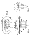
- Figure 1 is a front view of a fastener constructed in accordance with the teachings of the present invention;
- Figure 2 is a side view of the fastener of Figure 1;
- Figure 3 is a top view the fastener of Figure 1 illustrating the spacing of the structures in greater detail;
- Figure 4 is a front view of a fastener constructed in accordance with the teachings of an alternate embodiment of the present invention;
- Figure 5 is a side view of the fastener of Figure 5;
- Figure 6 is a top view of the fastener of Figure 5 illustrating the spacing of the structures in greater detail;
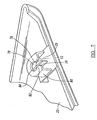
- Figure 7 is a perspective view of a trim component having a dog house attachment feature configured to engage the fastener according to the teachings of the present invention;
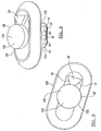
- Figure 8 represents a perspective view of an alternate fastener according to the teaching of the present invention; and
- Figure 9 represents a top view of the fastener shown in Figure 8.
- Referring to Figures 1 through 6, a
fastener 20 in accordance with the present invention is disclosed. Thefastener 20 is defined by aplastic body portion 22 which engages atrim component 23 having a doghouse engagement portion 24. Integral with the doghouse engagement portion 24 are a pair ofengagement surfaces abutting flange 28 which are used to engage themating surfaces 29 of thedog house 80. Additionally, thebody portion 22 has amating portion 30 which is formed by twosets 32 and 34 of threelocking members sets 32 and 34 of threelocking members proximal end 42 by an angled or wedge-shaped member 44. The twosets 32 and 34 of threelocking members umbrella portion 48. Each of the threelocking members teeth 50 which facilitate the coupling of theplastic body portion 22 to a sheet metal structure. - The
umbrella portion 48 functions to seal the mounting hole 53 in the sheet metal structure 51 and is formed of an ovalplanar portion 49 which is surrounded by a generally ovaldeformable portion 55. Theteeth 50 are configured to pull the deformable oval portion onto the sheet metal 51. Coupled to the distal end 46 and disposed on the sealingumbrella portion 48 is aretaining flange 52 of the doghouse engagement portion 24 which functions to laterally bind thefastener 22 to the dog house - Generally, the
abutting flange 28 of the doghouse engagement portion 24 is defined by the sides of triangular abuttingflange member 28. The triangular abuttingflange member 28 is defined by the pair of planarengaging surfaces engaging surfaces triangular insertion slot 62 defined in the dog house that facilitates the insertion of the doghouse engagement portion 24 into the dog house. - Disposed on the lower surface of the umbrella region is a pair of
engagement members engagement members 64 are generally perpendicular to thelower surface 69 of the sealingumbrella portion 48. Optionally, theseengagement members 64 can engage apertures formed in the sheet metal structure in order to prevent rotation of the fastener with respect to the sheet metal structure. Figures 1-3 depict a t-shaped engagement member 64 which hasrounded surfaces 65 which abut the surface of the aperture in the sheet metal structure. Figures 4-6 depictoval engagement members 66. Theengagement members 66 function to stand the engagement plastic fastener 20 a predetermined distance from the body panel surface. - Referring generally to Figures 1 and 4, is a view of dog
house engagement portion 24 coupled to theplastic body portion 22. The doghouse engagement portion 24 has a generally cylindrical-shaped member 68 and has theretaining flange 52. Theretaining flange 52 has asurface 70 which engages and interior surface of the dog house of the trim component. The generally cylindrical-shaped member 68 has a circularouter surface 72 which functions to guide the engagement portion between the angled insertion surfaces of the dog house. The circularouter surface 72 further functions to mate with a circular aperture defined within the dog house and prevent its lateral removal. The doghouse engagement portion 24 includes a connectingflange 74 that is configured to rigidly connect thetriangular flange member 28 to thecylindrical coupling member 72. - As can be seen in Figure 7, the
dog house 80 defines anupper keyhole slot 76 which allows displacement of the doghouse retention members 82. The dog house defines acircular aperture 84 having a diameter slightly larger than the diameter of cylindrical-shaped member 68. Thetriangular insertion slot 62 is defined between themating surfaces 29 of thedog house 80. Preferably, bothengagement surfaces mating surfaces 29 at the same time. This prevents rotation and translation of thefastener 20. - As shown in Figures 8 and 9, the
fastener 120 in accordance with another embodiment of the present invention is disclosed. Thefastener 120 is defined by aplastic body portion 122 having a doghouse engagement portion 124. Integral with the doghouse engagement portion 124 arepairs engagement surface flange 28 which are used to engage a surface of the doghouse engagement portion 124. Additionally, thebody portion 122 has a lockingportion 130 which is formed by twosets members sets members proximal end 42 by an angled or wedge-shapedmember 44. The two sets 32 and 34 of three lockingmembers umbrella portion 48. Each of the three lockingmembers teeth 50 which facilitate the coupling of theplastic body portion 22 to a sheet metal structure 51. The doghouse engagement portion 124 is acylindrical body 126 without a retaining flange. - The foregoing discussion discloses and describes exemplary embodiments of the present invention. One skilled in the art will readily recognize from such a discussion, and from the accompanying drawings and claims that various changes, modifications, and variations can be made therein without departing from the scope of the invention.
Claims (12)
- A fastener (20) for coupling a component (23) having a dog house engagement feature to an aperture comprising:a body portion (22) having a dog house engagement portion (24), and a locking portion (30) configured to be mated with the aperture,said the locking portion (30) comprising a plurality of deformable locking members (36, 38, 40) ;said dog house engagement portion (24) defining an abutting flange (28) coupled to the body portion, andan umbrella member (48) coupled to the dog house engagement portion (24),
characterised in thatthe abutting flange (28) is configured to engage an engagement surfaces (29) surface defined on the dog house (80) so as to prevent rotation of the body portion with respect to the dog house, and the deformable locking members (36, 38, 40) are coupled with a first end to the umbrella member (48). - The fastener according to Claim 1 wherein the umbrella member is configured to fluidly seal the aperture.
- The fastener according to anyone of Claims 1 and 2 wherein each deformable locking member defines a tooth (50) configured to engage the aperture.
- The fastener according to anyone of Claims 1 to 3 wherein the deformable members (36,38,40) are coupled with a second end to a wedged-shaped member (44).
- The fastener according to Claim 1 wherein the abutting flange (28) is configured to couple with a triangular insertion slot (62) defined by the dog house (80).
- The fastener according to Claim 5 wherein the abutting flange (28) is a triangular flange.
- The fastener according to Claim 6 wherein the triangular abutting flange (28) has a pair of flat bearing surfaces (26, 27).
- The fastener according to anyone of the preceding Claims wherein the dog house engagement portion (24) defines a cylindrical shaped member (68) configured to couple to an aperture (84) defined by the dog house (80).
- The fastener according to anyone of the preceding Claims wherein the body portion (22) comprises a engagement member (64) configured to engage an aperture.
- The fastener according to anyone of the preceding Claims wherein the body portion (22) comprises a engagement member (66) configured to limit the insertion of the fastener into the aperture.
- The fastener according to anyone of the preceding Claims wherein the umbrella portion (48) defines a generally oval base and an oval deformable portion.
- The fastener according to Claim 1 wherein the locking portion (30) is a wedge-shaped member (44) defining a plurality of deformable flanges.
Applications Claiming Priority (2)
| Application Number | Priority Date | Filing Date | Title |
|---|---|---|---|
| US47674503P | 2003-06-06 | 2003-06-06 | |
| US476745P | 2003-06-06 |
Publications (2)
| Publication Number | Publication Date |
|---|---|
| EP1484513A1 EP1484513A1 (en) | 2004-12-08 |
| EP1484513B1 true EP1484513B1 (en) | 2007-03-28 |
Family
ID=33159892
Family Applications (1)
| Application Number | Title | Priority Date | Filing Date |
|---|---|---|---|
| EP20040012898 Expired - Fee Related EP1484513B1 (en) | 2003-06-06 | 2004-06-01 | Resilient fastener with means for preventing rotation |
Country Status (3)
| Country | Link |
|---|---|
| EP (1) | EP1484513B1 (en) |
| DE (1) | DE602004005534T2 (en) |
| ES (1) | ES2282759T3 (en) |
Families Citing this family (5)
| Publication number | Priority date | Publication date | Assignee | Title |
|---|---|---|---|---|
| DE102009032583A1 (en) * | 2009-07-10 | 2011-01-13 | Audi Ag | Device for mounting covering part at door of motor vehicle, has projection cooperating with recess of receiving or latching elements such that latching element is inserted into receiving element by adjusting latching element |
| DE202017107162U1 (en) * | 2017-11-27 | 2019-03-01 | Rehau Ag + Co | System for connecting a first component to a second component |
| DE202017006630U1 (en) * | 2017-12-27 | 2019-04-01 | Rehau Ag + Co | System for connecting a first component to a second component |
| DE202017006631U1 (en) * | 2017-12-27 | 2019-04-01 | Rehau Ag + Co | System for connecting a first component to a second component |
| CN109163162A (en) * | 2018-11-02 | 2019-01-08 | 珠海格力电器股份有限公司 | Connector, pipe mounting structure and device is drunk only |
Family Cites Families (4)
| Publication number | Priority date | Publication date | Assignee | Title |
|---|---|---|---|---|
| US3771275A (en) * | 1970-04-08 | 1973-11-13 | Trw Inc | Retainer for a headed member |
| EP0020308A1 (en) * | 1979-04-27 | 1980-12-10 | Sergio Morello | Device for anchoring foam material panels to a relevant supporting structure |
| US5507610A (en) * | 1994-07-27 | 1996-04-16 | Emhart Inc. | Refusable fastener including a pin and grommet |
| US6196607B1 (en) * | 1999-09-09 | 2001-03-06 | Patent Holding Company | Trim panel assembly and plastic interior trim panel for use therein |
-
2004
- 2004-06-01 ES ES04012898T patent/ES2282759T3/en active Active
- 2004-06-01 DE DE200460005534 patent/DE602004005534T2/en not_active Expired - Fee Related
- 2004-06-01 EP EP20040012898 patent/EP1484513B1/en not_active Expired - Fee Related
Also Published As
| Publication number | Publication date |
|---|---|
| EP1484513A1 (en) | 2004-12-08 |
| DE602004005534T2 (en) | 2007-12-06 |
| DE602004005534D1 (en) | 2007-05-10 |
| ES2282759T3 (en) | 2007-10-16 |
Similar Documents
| Publication | Publication Date | Title |
|---|---|---|
| US7114221B2 (en) | Two-piece interior trim retainer | |
| US6928705B2 (en) | Low insertion effort U-base retainer | |
| US7287945B2 (en) | Low insertion effort fastener with offset for wing | |
| US7134170B2 (en) | Plastic retaining clip for rib attachment | |
| US7272873B2 (en) | Sill plate retainer | |
| US5884434A (en) | Door handle to latch rod connection | |
| US7536755B2 (en) | Clip having engaging pawl portions and projecting portions | |
| US6176660B1 (en) | Releasable fastener with lateral stabilizing brace members and latch legs carrying fastener insertion guide | |
| EP1696141B1 (en) | Tethered retainer assembly | |
| US5788268A (en) | Spring retainer air bag mounting device | |
| US6131339A (en) | Window assembly and mount for a window assembly | |
| JP2001063364A (en) | Fastener | |
| EP1134124A1 (en) | Attachment devices | |
| EP1484513B1 (en) | Resilient fastener with means for preventing rotation | |
| KR20080021772A (en) | Clip | |
| JPH11230135A (en) | Article installation fixture | |
| US7255365B2 (en) | Air bag module with adjustable cover | |
| JP2005138771A (en) | Fixing structure of tank protector | |
| JP4270490B2 (en) | Clearance adjustment method | |
| JPH038538Y2 (en) | ||
| JPH07332334A (en) | Floor carpet fixing tool | |
| JPH0671317U (en) | Interior parts mounting structure | |
| JPH0673419U (en) | clip | |
| JP2000245037A (en) | Fixing structure of wire harness |
Legal Events
| Date | Code | Title | Description |
|---|---|---|---|
| PUAI | Public reference made under article 153(3) epc to a published international application that has entered the european phase |
Free format text: ORIGINAL CODE: 0009012 |
|
| AK | Designated contracting states |
Kind code of ref document: A1 Designated state(s): AT BE BG CH CY CZ DE DK EE ES FI FR GB GR HU IE IT LI LU MC NL PL PT RO SE SI SK TR |
|
| AX | Request for extension of the european patent |
Extension state: AL HR LT LV MK |
|
| 17P | Request for examination filed |
Effective date: 20050527 |
|
| AKX | Designation fees paid |
Designated state(s): DE ES FR |
|
| GRAP | Despatch of communication of intention to grant a patent |
Free format text: ORIGINAL CODE: EPIDOSNIGR1 |
|
| GRAS | Grant fee paid |
Free format text: ORIGINAL CODE: EPIDOSNIGR3 |
|
| GRAA | (expected) grant |
Free format text: ORIGINAL CODE: 0009210 |
|
| AK | Designated contracting states |
Kind code of ref document: B1 Designated state(s): DE ES FR |
|
| REF | Corresponds to: |
Ref document number: 602004005534 Country of ref document: DE Date of ref document: 20070510 Kind code of ref document: P |
|
| PGFP | Annual fee paid to national office [announced via postgrant information from national office to epo] |
Ref country code: ES Payment date: 20070626 Year of fee payment: 4 |
|
| PGFP | Annual fee paid to national office [announced via postgrant information from national office to epo] |
Ref country code: DE Payment date: 20070731 Year of fee payment: 4 |
|
| ET | Fr: translation filed | ||
| REG | Reference to a national code |
Ref country code: ES Ref legal event code: FG2A Ref document number: 2282759 Country of ref document: ES Kind code of ref document: T3 |
|
| PLBE | No opposition filed within time limit |
Free format text: ORIGINAL CODE: 0009261 |
|
| STAA | Information on the status of an ep patent application or granted ep patent |
Free format text: STATUS: NO OPPOSITION FILED WITHIN TIME LIMIT |
|
| 26N | No opposition filed |
Effective date: 20080102 |
|
| PGFP | Annual fee paid to national office [announced via postgrant information from national office to epo] |
Ref country code: FR Payment date: 20070618 Year of fee payment: 4 |
|
| PG25 | Lapsed in a contracting state [announced via postgrant information from national office to epo] |
Ref country code: DE Free format text: LAPSE BECAUSE OF NON-PAYMENT OF DUE FEES Effective date: 20090101 |
|
| REG | Reference to a national code |
Ref country code: ES Ref legal event code: FD2A Effective date: 20080602 |
|
| PG25 | Lapsed in a contracting state [announced via postgrant information from national office to epo] |
Ref country code: ES Free format text: LAPSE BECAUSE OF NON-PAYMENT OF DUE FEES Effective date: 20080602 |
|
| REG | Reference to a national code |
Ref country code: FR Ref legal event code: ST Effective date: 20110729 |
|
| PG25 | Lapsed in a contracting state [announced via postgrant information from national office to epo] |
Ref country code: FR Free format text: LAPSE BECAUSE OF NON-PAYMENT OF DUE FEES Effective date: 20080630 |