EP1693238A1 - Vehicle driving mechanism - Google Patents
Vehicle driving mechanism Download PDFInfo
- Publication number
- EP1693238A1 EP1693238A1 EP04819377A EP04819377A EP1693238A1 EP 1693238 A1 EP1693238 A1 EP 1693238A1 EP 04819377 A EP04819377 A EP 04819377A EP 04819377 A EP04819377 A EP 04819377A EP 1693238 A1 EP1693238 A1 EP 1693238A1
- Authority
- EP
- European Patent Office
- Prior art keywords
- gear
- output shaft
- drive
- electric motor
- shaft
- Prior art date
- Legal status (The legal status is an assumption and is not a legal conclusion. Google has not performed a legal analysis and makes no representation as to the accuracy of the status listed.)
- Granted
Links
Images



Classifications
-
- B—PERFORMING OPERATIONS; TRANSPORTING
- B60—VEHICLES IN GENERAL
- B60K—ARRANGEMENT OR MOUNTING OF PROPULSION UNITS OR OF TRANSMISSIONS IN VEHICLES; ARRANGEMENT OR MOUNTING OF PLURAL DIVERSE PRIME-MOVERS IN VEHICLES; AUXILIARY DRIVES FOR VEHICLES; INSTRUMENTATION OR DASHBOARDS FOR VEHICLES; ARRANGEMENTS IN CONNECTION WITH COOLING, AIR INTAKE, GAS EXHAUST OR FUEL SUPPLY OF PROPULSION UNITS IN VEHICLES
- B60K6/00—Arrangement or mounting of plural diverse prime-movers for mutual or common propulsion, e.g. hybrid propulsion systems comprising electric motors and internal combustion engines
- B60K6/20—Arrangement or mounting of plural diverse prime-movers for mutual or common propulsion, e.g. hybrid propulsion systems comprising electric motors and internal combustion engines the prime-movers consisting of electric motors and internal combustion engines, e.g. HEVs
- B60K6/22—Arrangement or mounting of plural diverse prime-movers for mutual or common propulsion, e.g. hybrid propulsion systems comprising electric motors and internal combustion engines the prime-movers consisting of electric motors and internal combustion engines, e.g. HEVs characterised by apparatus, components or means specially adapted for HEVs
- B60K6/36—Arrangement or mounting of plural diverse prime-movers for mutual or common propulsion, e.g. hybrid propulsion systems comprising electric motors and internal combustion engines the prime-movers consisting of electric motors and internal combustion engines, e.g. HEVs characterised by apparatus, components or means specially adapted for HEVs characterised by the transmission gearings
-
- B—PERFORMING OPERATIONS; TRANSPORTING
- B60—VEHICLES IN GENERAL
- B60K—ARRANGEMENT OR MOUNTING OF PROPULSION UNITS OR OF TRANSMISSIONS IN VEHICLES; ARRANGEMENT OR MOUNTING OF PLURAL DIVERSE PRIME-MOVERS IN VEHICLES; AUXILIARY DRIVES FOR VEHICLES; INSTRUMENTATION OR DASHBOARDS FOR VEHICLES; ARRANGEMENTS IN CONNECTION WITH COOLING, AIR INTAKE, GAS EXHAUST OR FUEL SUPPLY OF PROPULSION UNITS IN VEHICLES
- B60K6/00—Arrangement or mounting of plural diverse prime-movers for mutual or common propulsion, e.g. hybrid propulsion systems comprising electric motors and internal combustion engines
- B60K6/20—Arrangement or mounting of plural diverse prime-movers for mutual or common propulsion, e.g. hybrid propulsion systems comprising electric motors and internal combustion engines the prime-movers consisting of electric motors and internal combustion engines, e.g. HEVs
- B60K6/22—Arrangement or mounting of plural diverse prime-movers for mutual or common propulsion, e.g. hybrid propulsion systems comprising electric motors and internal combustion engines the prime-movers consisting of electric motors and internal combustion engines, e.g. HEVs characterised by apparatus, components or means specially adapted for HEVs
- B60K6/40—Arrangement or mounting of plural diverse prime-movers for mutual or common propulsion, e.g. hybrid propulsion systems comprising electric motors and internal combustion engines the prime-movers consisting of electric motors and internal combustion engines, e.g. HEVs characterised by apparatus, components or means specially adapted for HEVs characterised by the assembly or relative disposition of components
-
- B—PERFORMING OPERATIONS; TRANSPORTING
- B60—VEHICLES IN GENERAL
- B60K—ARRANGEMENT OR MOUNTING OF PROPULSION UNITS OR OF TRANSMISSIONS IN VEHICLES; ARRANGEMENT OR MOUNTING OF PLURAL DIVERSE PRIME-MOVERS IN VEHICLES; AUXILIARY DRIVES FOR VEHICLES; INSTRUMENTATION OR DASHBOARDS FOR VEHICLES; ARRANGEMENTS IN CONNECTION WITH COOLING, AIR INTAKE, GAS EXHAUST OR FUEL SUPPLY OF PROPULSION UNITS IN VEHICLES
- B60K6/00—Arrangement or mounting of plural diverse prime-movers for mutual or common propulsion, e.g. hybrid propulsion systems comprising electric motors and internal combustion engines
- B60K6/20—Arrangement or mounting of plural diverse prime-movers for mutual or common propulsion, e.g. hybrid propulsion systems comprising electric motors and internal combustion engines the prime-movers consisting of electric motors and internal combustion engines, e.g. HEVs
- B60K6/22—Arrangement or mounting of plural diverse prime-movers for mutual or common propulsion, e.g. hybrid propulsion systems comprising electric motors and internal combustion engines the prime-movers consisting of electric motors and internal combustion engines, e.g. HEVs characterised by apparatus, components or means specially adapted for HEVs
- B60K6/40—Arrangement or mounting of plural diverse prime-movers for mutual or common propulsion, e.g. hybrid propulsion systems comprising electric motors and internal combustion engines the prime-movers consisting of electric motors and internal combustion engines, e.g. HEVs characterised by apparatus, components or means specially adapted for HEVs characterised by the assembly or relative disposition of components
- B60K6/405—Housings
-
- B—PERFORMING OPERATIONS; TRANSPORTING
- B60—VEHICLES IN GENERAL
- B60K—ARRANGEMENT OR MOUNTING OF PROPULSION UNITS OR OF TRANSMISSIONS IN VEHICLES; ARRANGEMENT OR MOUNTING OF PLURAL DIVERSE PRIME-MOVERS IN VEHICLES; AUXILIARY DRIVES FOR VEHICLES; INSTRUMENTATION OR DASHBOARDS FOR VEHICLES; ARRANGEMENTS IN CONNECTION WITH COOLING, AIR INTAKE, GAS EXHAUST OR FUEL SUPPLY OF PROPULSION UNITS IN VEHICLES
- B60K6/00—Arrangement or mounting of plural diverse prime-movers for mutual or common propulsion, e.g. hybrid propulsion systems comprising electric motors and internal combustion engines
- B60K6/20—Arrangement or mounting of plural diverse prime-movers for mutual or common propulsion, e.g. hybrid propulsion systems comprising electric motors and internal combustion engines the prime-movers consisting of electric motors and internal combustion engines, e.g. HEVs
- B60K6/42—Arrangement or mounting of plural diverse prime-movers for mutual or common propulsion, e.g. hybrid propulsion systems comprising electric motors and internal combustion engines the prime-movers consisting of electric motors and internal combustion engines, e.g. HEVs characterised by the architecture of the hybrid electric vehicle
- B60K6/48—Parallel type
-
- B—PERFORMING OPERATIONS; TRANSPORTING
- B60—VEHICLES IN GENERAL
- B60K—ARRANGEMENT OR MOUNTING OF PROPULSION UNITS OR OF TRANSMISSIONS IN VEHICLES; ARRANGEMENT OR MOUNTING OF PLURAL DIVERSE PRIME-MOVERS IN VEHICLES; AUXILIARY DRIVES FOR VEHICLES; INSTRUMENTATION OR DASHBOARDS FOR VEHICLES; ARRANGEMENTS IN CONNECTION WITH COOLING, AIR INTAKE, GAS EXHAUST OR FUEL SUPPLY OF PROPULSION UNITS IN VEHICLES
- B60K6/00—Arrangement or mounting of plural diverse prime-movers for mutual or common propulsion, e.g. hybrid propulsion systems comprising electric motors and internal combustion engines
- B60K6/20—Arrangement or mounting of plural diverse prime-movers for mutual or common propulsion, e.g. hybrid propulsion systems comprising electric motors and internal combustion engines the prime-movers consisting of electric motors and internal combustion engines, e.g. HEVs
- B60K6/50—Architecture of the driveline characterised by arrangement or kind of transmission units
- B60K6/54—Transmission for changing ratio
- B60K6/547—Transmission for changing ratio the transmission being a stepped gearing
-
- B—PERFORMING OPERATIONS; TRANSPORTING
- B60—VEHICLES IN GENERAL
- B60L—PROPULSION OF ELECTRICALLY-PROPELLED VEHICLES; SUPPLYING ELECTRIC POWER FOR AUXILIARY EQUIPMENT OF ELECTRICALLY-PROPELLED VEHICLES; ELECTRODYNAMIC BRAKE SYSTEMS FOR VEHICLES IN GENERAL; MAGNETIC SUSPENSION OR LEVITATION FOR VEHICLES; MONITORING OPERATING VARIABLES OF ELECTRICALLY-PROPELLED VEHICLES; ELECTRIC SAFETY DEVICES FOR ELECTRICALLY-PROPELLED VEHICLES
- B60L15/00—Methods, circuits, or devices for controlling the traction-motor speed of electrically-propelled vehicles
- B60L15/20—Methods, circuits, or devices for controlling the traction-motor speed of electrically-propelled vehicles for control of the vehicle or its driving motor to achieve a desired performance, e.g. speed, torque, programmed variation of speed
-
- B—PERFORMING OPERATIONS; TRANSPORTING
- B60—VEHICLES IN GENERAL
- B60L—PROPULSION OF ELECTRICALLY-PROPELLED VEHICLES; SUPPLYING ELECTRIC POWER FOR AUXILIARY EQUIPMENT OF ELECTRICALLY-PROPELLED VEHICLES; ELECTRODYNAMIC BRAKE SYSTEMS FOR VEHICLES IN GENERAL; MAGNETIC SUSPENSION OR LEVITATION FOR VEHICLES; MONITORING OPERATING VARIABLES OF ELECTRICALLY-PROPELLED VEHICLES; ELECTRIC SAFETY DEVICES FOR ELECTRICALLY-PROPELLED VEHICLES
- B60L50/00—Electric propulsion with power supplied within the vehicle
- B60L50/10—Electric propulsion with power supplied within the vehicle using propulsion power supplied by engine-driven generators, e.g. generators driven by combustion engines
- B60L50/16—Electric propulsion with power supplied within the vehicle using propulsion power supplied by engine-driven generators, e.g. generators driven by combustion engines with provision for separate direct mechanical propulsion
-
- B—PERFORMING OPERATIONS; TRANSPORTING
- B60—VEHICLES IN GENERAL
- B60K—ARRANGEMENT OR MOUNTING OF PROPULSION UNITS OR OF TRANSMISSIONS IN VEHICLES; ARRANGEMENT OR MOUNTING OF PLURAL DIVERSE PRIME-MOVERS IN VEHICLES; AUXILIARY DRIVES FOR VEHICLES; INSTRUMENTATION OR DASHBOARDS FOR VEHICLES; ARRANGEMENTS IN CONNECTION WITH COOLING, AIR INTAKE, GAS EXHAUST OR FUEL SUPPLY OF PROPULSION UNITS IN VEHICLES
- B60K6/00—Arrangement or mounting of plural diverse prime-movers for mutual or common propulsion, e.g. hybrid propulsion systems comprising electric motors and internal combustion engines
- B60K6/20—Arrangement or mounting of plural diverse prime-movers for mutual or common propulsion, e.g. hybrid propulsion systems comprising electric motors and internal combustion engines the prime-movers consisting of electric motors and internal combustion engines, e.g. HEVs
- B60K6/42—Arrangement or mounting of plural diverse prime-movers for mutual or common propulsion, e.g. hybrid propulsion systems comprising electric motors and internal combustion engines the prime-movers consisting of electric motors and internal combustion engines, e.g. HEVs characterised by the architecture of the hybrid electric vehicle
- B60K6/48—Parallel type
- B60K2006/4808—Electric machine connected or connectable to gearbox output shaft
-
- B—PERFORMING OPERATIONS; TRANSPORTING
- B60—VEHICLES IN GENERAL
- B60K—ARRANGEMENT OR MOUNTING OF PROPULSION UNITS OR OF TRANSMISSIONS IN VEHICLES; ARRANGEMENT OR MOUNTING OF PLURAL DIVERSE PRIME-MOVERS IN VEHICLES; AUXILIARY DRIVES FOR VEHICLES; INSTRUMENTATION OR DASHBOARDS FOR VEHICLES; ARRANGEMENTS IN CONNECTION WITH COOLING, AIR INTAKE, GAS EXHAUST OR FUEL SUPPLY OF PROPULSION UNITS IN VEHICLES
- B60K5/00—Arrangement or mounting of internal-combustion or jet-propulsion units
- B60K5/04—Arrangement or mounting of internal-combustion or jet-propulsion units with the engine main axis, e.g. crankshaft axis, transversely to the longitudinal centre line of the vehicle
-
- B—PERFORMING OPERATIONS; TRANSPORTING
- B60—VEHICLES IN GENERAL
- B60L—PROPULSION OF ELECTRICALLY-PROPELLED VEHICLES; SUPPLYING ELECTRIC POWER FOR AUXILIARY EQUIPMENT OF ELECTRICALLY-PROPELLED VEHICLES; ELECTRODYNAMIC BRAKE SYSTEMS FOR VEHICLES IN GENERAL; MAGNETIC SUSPENSION OR LEVITATION FOR VEHICLES; MONITORING OPERATING VARIABLES OF ELECTRICALLY-PROPELLED VEHICLES; ELECTRIC SAFETY DEVICES FOR ELECTRICALLY-PROPELLED VEHICLES
- B60L2210/00—Converter types
- B60L2210/40—DC to AC converters
-
- B—PERFORMING OPERATIONS; TRANSPORTING
- B60—VEHICLES IN GENERAL
- B60L—PROPULSION OF ELECTRICALLY-PROPELLED VEHICLES; SUPPLYING ELECTRIC POWER FOR AUXILIARY EQUIPMENT OF ELECTRICALLY-PROPELLED VEHICLES; ELECTRODYNAMIC BRAKE SYSTEMS FOR VEHICLES IN GENERAL; MAGNETIC SUSPENSION OR LEVITATION FOR VEHICLES; MONITORING OPERATING VARIABLES OF ELECTRICALLY-PROPELLED VEHICLES; ELECTRIC SAFETY DEVICES FOR ELECTRICALLY-PROPELLED VEHICLES
- B60L2240/00—Control parameters of input or output; Target parameters
- B60L2240/10—Vehicle control parameters
- B60L2240/12—Speed
-
- B—PERFORMING OPERATIONS; TRANSPORTING
- B60—VEHICLES IN GENERAL
- B60L—PROPULSION OF ELECTRICALLY-PROPELLED VEHICLES; SUPPLYING ELECTRIC POWER FOR AUXILIARY EQUIPMENT OF ELECTRICALLY-PROPELLED VEHICLES; ELECTRODYNAMIC BRAKE SYSTEMS FOR VEHICLES IN GENERAL; MAGNETIC SUSPENSION OR LEVITATION FOR VEHICLES; MONITORING OPERATING VARIABLES OF ELECTRICALLY-PROPELLED VEHICLES; ELECTRIC SAFETY DEVICES FOR ELECTRICALLY-PROPELLED VEHICLES
- B60L2240/00—Control parameters of input or output; Target parameters
- B60L2240/40—Drive Train control parameters
- B60L2240/42—Drive Train control parameters related to electric machines
- B60L2240/421—Speed
-
- B—PERFORMING OPERATIONS; TRANSPORTING
- B60—VEHICLES IN GENERAL
- B60L—PROPULSION OF ELECTRICALLY-PROPELLED VEHICLES; SUPPLYING ELECTRIC POWER FOR AUXILIARY EQUIPMENT OF ELECTRICALLY-PROPELLED VEHICLES; ELECTRODYNAMIC BRAKE SYSTEMS FOR VEHICLES IN GENERAL; MAGNETIC SUSPENSION OR LEVITATION FOR VEHICLES; MONITORING OPERATING VARIABLES OF ELECTRICALLY-PROPELLED VEHICLES; ELECTRIC SAFETY DEVICES FOR ELECTRICALLY-PROPELLED VEHICLES
- B60L2240/00—Control parameters of input or output; Target parameters
- B60L2240/40—Drive Train control parameters
- B60L2240/42—Drive Train control parameters related to electric machines
- B60L2240/423—Torque
-
- F—MECHANICAL ENGINEERING; LIGHTING; HEATING; WEAPONS; BLASTING
- F16—ENGINEERING ELEMENTS AND UNITS; GENERAL MEASURES FOR PRODUCING AND MAINTAINING EFFECTIVE FUNCTIONING OF MACHINES OR INSTALLATIONS; THERMAL INSULATION IN GENERAL
- F16H—GEARING
- F16H3/00—Toothed gearings for conveying rotary motion with variable gear ratio or for reversing rotary motion
- F16H3/02—Toothed gearings for conveying rotary motion with variable gear ratio or for reversing rotary motion without gears having orbital motion
- F16H3/08—Toothed gearings for conveying rotary motion with variable gear ratio or for reversing rotary motion without gears having orbital motion exclusively or essentially with continuously meshing gears, that can be disengaged from their shafts
- F16H3/087—Toothed gearings for conveying rotary motion with variable gear ratio or for reversing rotary motion without gears having orbital motion exclusively or essentially with continuously meshing gears, that can be disengaged from their shafts characterised by the disposition of the gears
- F16H3/089—Toothed gearings for conveying rotary motion with variable gear ratio or for reversing rotary motion without gears having orbital motion exclusively or essentially with continuously meshing gears, that can be disengaged from their shafts characterised by the disposition of the gears all of the meshing gears being supported by a pair of parallel shafts, one being the input shaft and the other the output shaft, there being no countershaft involved
-
- Y—GENERAL TAGGING OF NEW TECHNOLOGICAL DEVELOPMENTS; GENERAL TAGGING OF CROSS-SECTIONAL TECHNOLOGIES SPANNING OVER SEVERAL SECTIONS OF THE IPC; TECHNICAL SUBJECTS COVERED BY FORMER USPC CROSS-REFERENCE ART COLLECTIONS [XRACs] AND DIGESTS
- Y02—TECHNOLOGIES OR APPLICATIONS FOR MITIGATION OR ADAPTATION AGAINST CLIMATE CHANGE
- Y02T—CLIMATE CHANGE MITIGATION TECHNOLOGIES RELATED TO TRANSPORTATION
- Y02T10/00—Road transport of goods or passengers
- Y02T10/60—Other road transportation technologies with climate change mitigation effect
- Y02T10/62—Hybrid vehicles
-
- Y—GENERAL TAGGING OF NEW TECHNOLOGICAL DEVELOPMENTS; GENERAL TAGGING OF CROSS-SECTIONAL TECHNOLOGIES SPANNING OVER SEVERAL SECTIONS OF THE IPC; TECHNICAL SUBJECTS COVERED BY FORMER USPC CROSS-REFERENCE ART COLLECTIONS [XRACs] AND DIGESTS
- Y02—TECHNOLOGIES OR APPLICATIONS FOR MITIGATION OR ADAPTATION AGAINST CLIMATE CHANGE
- Y02T—CLIMATE CHANGE MITIGATION TECHNOLOGIES RELATED TO TRANSPORTATION
- Y02T10/00—Road transport of goods or passengers
- Y02T10/60—Other road transportation technologies with climate change mitigation effect
- Y02T10/64—Electric machine technologies in electromobility
-
- Y—GENERAL TAGGING OF NEW TECHNOLOGICAL DEVELOPMENTS; GENERAL TAGGING OF CROSS-SECTIONAL TECHNOLOGIES SPANNING OVER SEVERAL SECTIONS OF THE IPC; TECHNICAL SUBJECTS COVERED BY FORMER USPC CROSS-REFERENCE ART COLLECTIONS [XRACs] AND DIGESTS
- Y02—TECHNOLOGIES OR APPLICATIONS FOR MITIGATION OR ADAPTATION AGAINST CLIMATE CHANGE
- Y02T—CLIMATE CHANGE MITIGATION TECHNOLOGIES RELATED TO TRANSPORTATION
- Y02T10/00—Road transport of goods or passengers
- Y02T10/60—Other road transportation technologies with climate change mitigation effect
- Y02T10/7072—Electromobility specific charging systems or methods for batteries, ultracapacitors, supercapacitors or double-layer capacitors
-
- Y—GENERAL TAGGING OF NEW TECHNOLOGICAL DEVELOPMENTS; GENERAL TAGGING OF CROSS-SECTIONAL TECHNOLOGIES SPANNING OVER SEVERAL SECTIONS OF THE IPC; TECHNICAL SUBJECTS COVERED BY FORMER USPC CROSS-REFERENCE ART COLLECTIONS [XRACs] AND DIGESTS
- Y02—TECHNOLOGIES OR APPLICATIONS FOR MITIGATION OR ADAPTATION AGAINST CLIMATE CHANGE
- Y02T—CLIMATE CHANGE MITIGATION TECHNOLOGIES RELATED TO TRANSPORTATION
- Y02T10/00—Road transport of goods or passengers
- Y02T10/60—Other road transportation technologies with climate change mitigation effect
- Y02T10/72—Electric energy management in electromobility
Definitions
- This invention relates to the drive mechanism for a vehicle, and more particularly to a drive mechanism that has two kinds of driving sources (engines/motors), and that moves the vehicle by using both driving sources together or by switching between them.
- AMT automatic-manual transmission
- an automatic-clutch mechanism, and automatic-transmission mechanism are installed in a manually operated gear-engagement-type transmission, which has excellent transmission efficiency, and controlled electronically
- the clutch operation and gear- shifting operation are performed automatically according to the amount of acceleration given by the driver and the operating state of the vehicle, however, when shifting gears, the clutch is released and a gear-shifting operation is performed, so during that time the engine's driving force is lost and there is a feeling of so-called sluggishness.
- hybrid vehicles designed for obtaining low-levels of exhaust gas and low fuel consumption have received much attention; and as a method of reducing or preventing the aforementioned sluggishness, a method is under study in which an electric motor is used as a second driving source, and when the clutch is released, the driving force of the motor is transmitted to the tires to prevent a decrease in driving force.
- a hybrid vehicle that uses this method is called an automatic- manual transmission hybrid vehicle (AMT-HV), and reference documents related to this include Japanese Patent Kokai Publications No.H11-69509-A, No.H11-141665-A, and No.2002-160540-A.
- the output from an internal-combustion engine is transmitted to the drive wheels by way of the transmission and differential, and the motor that functions as a second driving source is connected between the transmission and differential by a gear mechanism.
- the clutch is released, the driving force from the motor is transmitted to the differential and drive wheels by way of a drive mechanism, so, respectively, it is possible to prevent a loss of driving force and alleviate the feeling of sluggishness.
- Patent Document 1 Japanese Patent Kokai Publication No.H11-69509
- Patent Document 2 Japanese Patent Kokai Publication No.H11-141665
- Patent Document 1 Japanese Patent Kokai Publication No.H11-160540
- the distance between the drive shaft (66 in FIG. 5) and the rotating shaft (71 in FIG. 5) of the motor is determined by creating the necessary reduction ratio between the motor (70 in FIG. 5) and the differential (63 in FIG. 5) (expressed as the ratio r2/r1 of the radius r1 of a gear (71A in FIG. 5) that is formed around the rotating shaft (71 in FIG. 5) of the motor shown in FIG. 5, and the radius r2 of a ring gear (63A in FIG. 5) on the side of the differential (63 in FIG.
- a vehicle drive mechanism comprises: an engine, an automatic transmission, a first drive gear formed on the output shaft of the automatic transmission, and a differential apparatus that transmits torque from the aforementioned output shaft that was input by way of the first drive gear to the drive wheels; and that by using an electric motor is capable of assisting the torque without changing the basic construction of the automatic transmission (AMT) portion.
- AMT automatic transmission
- the electric-motor side comprises: a prime-driving gear formed on the output shaft of the electric motor that is arranged parallel with the output shaft of the transmission, an intermediate reduction shaft that is arranged parallel with the output shafts of both the transmission and electric motor; and a second drive gear that is formed on the intermediate reduction shaft and that transmits torque from the output shaft of the electric motor to the differential apparatus.
- the drive force from the engine acts only on the power transmission portion of the automatic transmission, so most of the parts can be shared, making it possible to lower cost, and when compared with the same kind of conventional mechanism, it is possible to obtain sufficient driving force and torque.
- the drive mechanism for a vehicle of this embodiment comprises: a first drive gear (49 in FIG. 1) that is formed around the output shaft (42 in FIG. 1) of a gear-type transmission (top of FIG. 1); and on the electric-motor side (bottom in FIG. 1), comprises a prime-driving gear (61 in FIG. 1) that is formed around an output shaft of an electric motor that is located parallel with the output shaft (42 in FIG. 1) of the transmission; and an intermediate reduction shaft (62 in FIG. 1) that is located parallel with the output shafts (42, 60 in FIG. 1) of the gear-type transmission and electric motor.
- a driven gear (63 in FIG. 1) that engages with the prime-driving gear (61 in FIG.
- the output from the electric motor (bottom in FIG. 1) acts on the differential (14 in FIG. 1), so there is no need to increase the strength of the support members for each of the gears and shafts (34, 42 in FIG. 1) of the automatic transmission (AMT), and it is possible to keep the construction of the transmission (AMT) portion as is; also when the clutch is released when shifting gears, the driving force from the motor drives the differential gear (14 in FIG. 1) by way of the reduction mechanism and second drive gear (64 in FIG. 1) according to the gear ratio between the prime-driving gear (61 in FIG. 1) and the first driven gear (63 in FIG. 1), thus making it possible to do away with the feeling of sluggishness.
- the rpm value that is obtained from the constantly operating rotational sensor (65 in FIG. 1) is proportional to the vehicle speed, so it can be used in the ECU (Electronic Control Unit) (not shown in the figure) for transmission control or drive control of the motor. Furthermore, by sending a signal to an indicator on the driver's side, it becomes possible to do away with a vehicle speed sensor that is placed near the conventional differential apparatus (14 in FIG. 1).
- FIG. 1 is a skeleton drawing showing the main construction (4-speed state) of the drive mechanism of this embodiment
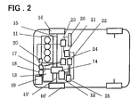
- FIG. 2 is a block diagram showing the construction of a hybrid vehicle in which the drive mechanism of this embodiment is installed.
- the hybrid vehicle of this embodiment has two kinds of driving sources, an engine as typified by an internal combustion engine (hereafter abbreviated as E/G) 11, and a motor generator (hereafter abbreviated as MG) 12 that is driven by electricity that is stored in a battery 19.
- E/G internal combustion engine
- MG motor generator
- the output from the engine 11 is transmitted to the transmission 13, and then, is transmitted to axle shafts 15, 15' and drive wheels 16, 16' by way of the differential apparatus 14 that functions as an output unit, and drives the vehicle.
- the output from the MG 12 can similarly move the vehicle by way of the differential apparatus 14.
- the hybrid vehicle of this embodiment also comprises: a HV-ECU 21 (Hybrid Vehicle Electronic Control Unit) that performs overall vehicle control; a MG-ECU and inverter 22 that gives instructions to the MG 12 to drive or regenerate; an E/G-ECU 23 that controls the stopping and ignition states of the engine 11; a clutch actuator 17 that is built into the transmission 13, an AMT-ECU 24 that controls a gear-shifting actuator 18 and performs optimum gear shifting; and a battery ECU 25 that controls the charging state of the battery 19.
- the HV-ECU 21 receives the driving intentions from the driver and controls and manages the MG-ECU and inverter 22, E/G-ECU 23 and battery ECU 25.
- the E/G-ECU 23 together with the AMT-ECU 24 produces the optimum ignition state, and performs ignitions control when starting the engine with a starter 20. Also, an indicator 26 that displays the speed of the vehicle is located near the driver's seat.
- a flywheel 32 is fastened to the end of an output shaft 31 of the engine 11, and a clutch element 33 is installed on the flywheel 32 and can be engaged or released by a clutch actuator 17.
- Driver members of the clutch are installed and integrated with the input shaft 34 of the transmission 13 in the direction of rotation with a spline or the like.
- the drive gears 1st 35, Rev 36 and 2nd 37 are arranged in order from the clutch side and mounted such that they are integrated with the input shaft 34, and furthermore drive gears 3rd 38, 4th 39, 5th 40 and 6th 41 are mounted so that they are toratable free.
- the output shaft 42 of the transmission 13 is located parallel with the input shaft 34, and driven gears 1st 43 and 2nd 44 are mounted on it so that they are free rotatable in locations where they can engage with the aforementioned gears, and driven gears 3rd 45, 4th 46, 5th 47 and 6th 48 are mounted such that they are integrated with the output shaft 42.
- a drive gear 49 is mounted on the end section on the clutch side of the output shaft 42 of the transmission 13 such that it is integrated with the output shaft 42, and it engages with a ring gear (final gear) 14A that is located on the case of the differential apparatus 14.
- a shaft 50 is located that is parallel with the input shaft 34 of the transmission 13, and a Reverse-idler gear 51 is mounted on this shaft 50 so that it rotates freely.
- the ilder gear can also move in the axial direction, and when it is in a location on the clutch side (thick solid line), it is not engaged with the Rev drive gear 36, however, when it is in a location on the side of the 6th drive gear 41, it can be engaged with the Rev drive gear 36.
- Hub members 52, 53, 54 that turn statically with each of the shafts are located between the drive gears and driven gears of the input shaft 34 and output shaft 42 of the transmission 13.
- Each of the hub members has a joint such as a spline on its outer surface, and furthermore by engaging with sleeves 55, 56, 57 that are located around their outer surface, and moving the sleeves in the axial direction (left-right in the figure) by the gear-shifting actuator 18, the sleeves can engage with a spline formed on the gear on the right side or the left side so that power can be transmitted, or can be in a neutral position where it is not engaged with any gears.
- FIG. 1 when the sleeve 57 moves to the right, it is in the 4-speed state.
- a gear 58 is located around the sleeve 55 on the output shaft 42 between 1st 43 and 2nd 44 in the portion that extends further outward, and when the Rev idler gear 51 is engaged with the Rev drive gear 36, gear 58 engages with the idler gear 51, so that it has two states, a neutral state and Rev drive state.
- the driving force that is output by MG 12 is transmitted to the prime-driving gear 61 that is located and integrated on the end of the MG output shaft 60.
- a driven gear 63 that engages with the prime-driving gear 61, and a second drive gear 64 that engages with a ring gear (final gear) 14A that is located on the case of the differential apparatus 14 are located on an intermediate reduction shaft 63 that is located parallel with the MG output shaft 60, and the drive force from MG 12 is transmitted to the second drive gear 64 at a specified reduction ratio.
- the output from the engine 11 and MG 12 is transmitted to the ring gear (final gear) 70, and by way of the differential apparatus 14, any difference in rpm is absorbed as needed, and the axle shaft 15, 15' and drive wheels 16, 16' are driven.
- the MG 12 has a power running state in which electric power is received and converted to driving force, and a generating state in which driving force is converted to electric power, and by using three-phase electric power to cause large electric current to flow at an optimal position for the magnetic force generated by a stator 66 to pass and return to an iron (steel) portion of the rotor, control, including control of the generation of driving force and the direction of rotation, is performed so that efficient conversion is possible.
- a resolver 65 is installed on the opposite side of the output shaft of MG 12 as an rpm detecting apparatus.
- the resolver 65 detects the relative angle between the rotor 67 that rotates integrally with the MG output shaft 60, which can then be used as a resolver signal. For example, by calculating a numerical value that depends on the number of poles of the MG 12 and the gear ratio on the side of the MG 12, it is possible to use the resolver signal as a vehicle speed signal.
- the signal drives the indicator 20 on the operation panel by way of the HV-ECU 21 and E/G-ECU.
- FIG. 3 is a cross-sectional drawing showing the detailed construction of the drive mechanism of this embodiment, where the ring gear (final gear) 70 located on outside of the case of the differential apparatus 14 engages with the first drive gear 49 on the output shaft 42 on the transmission side, and the second drive gear 64 of the intermediate reduction shaft 62 on the MG side. Also, the second drive gear 64 is constructed so that it is driven by way of the driven gear 63 located on the same shaft, and the prime-driving gear 61 on the side of the MG 12.
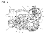
- FIG. 4 is a side view showing the detailed construction of the drive mechanism of this embodiment, where the bold dot-dashed circles in the drawing indicate the pitch circle of the prime-driving gear 61 and the pitch circle of the driven gear 63 of the intermediate reduction shaft 62, and the bold dotted circles indicate the position of the intermediate reduction shaft 62 on the MG side, and the pitch circles of the first and second drive gears 49, 64 and the ring gear (final gear) 14A located on the case of the differential apparatus 14.
- the drive mechanism of this embodiment can be constructed so that it has the form of an add-on to the an existing transmission 13.
- the resolver signal from the MG 12 is used as the vehicle-speed signal, so it is possible to do away with the vehicle-speed sensor that is attached to a conventional manually operated gear-engagement-type transmission, so construction is possible in which it is possible to make the vehicle drive mechanism more compact and lower cost.
- the drive mechanism of this invention is not limited to being used just when shifting gears, but is also capable of performing control using the driving force from the motor that functions as a second prime mover in situations of helping the driving force from the engine in order to increase the acceleration or increase the climbing power, running under just the drive motor, stopping or restarting the engine when the engine is stopped, or preventing down-slippage upon starting at a sloped road.
- the drive mechanism of this invention is not limited to being used just when shifting gears, but is also capable of performing control using the driving force from the motor that functions as a second prime mover in situations of helping the driving force from the engine in order to increase the acceleration or increase the climbing power, running under just the drive motor, stopping or restarting the engine when the engine is stopped, or preventing down-slippage upon starting at a sloped road.
- it is of course possible to assist the driving force of an engine that uses this regenerated energy which is very effective in improving fuel consumption.
Landscapes
- Engineering & Computer Science (AREA)
- Transportation (AREA)
- Mechanical Engineering (AREA)
- Chemical & Material Sciences (AREA)
- Combustion & Propulsion (AREA)
- Power Engineering (AREA)
- Electric Propulsion And Braking For Vehicles (AREA)
- Arrangement Of Transmissions (AREA)
- Hybrid Electric Vehicles (AREA)
- General Details Of Gearings (AREA)
Abstract
Description
- This invention relates to the drive mechanism for a vehicle, and more particularly to a drive mechanism that has two kinds of driving sources (engines/motors), and that moves the vehicle by using both driving sources together or by switching between them.
- In recent years, the development of an automatic-manual transmission (hereafter referred to as AMT) in which an automatic-clutch mechanism, and automatic-transmission mechanism are installed in a manually operated gear-engagement-type transmission, which has excellent transmission efficiency, and controlled electronically has been advancing. In this automatic-manual transmission method, the clutch operation and gear- shifting operation are performed automatically according to the amount of acceleration given by the driver and the operating state of the vehicle, however, when shifting gears, the clutch is released and a gear-shifting operation is performed, so during that time the engine's driving force is lost and there is a feeling of so-called sluggishness.
- Also, recently, hybrid vehicles designed for obtaining low-levels of exhaust gas and low fuel consumption have received much attention; and as a method of reducing or preventing the aforementioned sluggishness, a method is under study in which an electric motor is used as a second driving source, and when the clutch is released, the driving force of the motor is transmitted to the tires to prevent a decrease in driving force. A hybrid vehicle that uses this method is called an automatic- manual transmission hybrid vehicle (AMT-HV), and reference documents related to this include Japanese Patent Kokai Publications No.H11-69509-A, No.H11-141665-A, and No.2002-160540-A.
- In the transmission-control apparatus disclosed in Japanese Patent Kokai Publication No.H11-69509-A, the output from an internal-combustion engine is transmitted to the drive wheels by way of the transmission and differential, and the motor that functions as a second driving source is connected between the transmission and differential by a gear mechanism. Moreover, when the clutch is released, the driving force from the motor is transmitted to the differential and drive wheels by way of a drive mechanism, so, respectively, it is possible to prevent a loss of driving force and alleviate the feeling of sluggishness.
- Moreover, in Japanese Patent Kokai Publication No.H11-141665-A, an automatic transmission is introduced in which a gear mechanism (connected to the 4-speed gear as shown in FIG. 1 of the publication) that transmits the motor output is installed inside the transmission, and, reportedly, similarly makes it possible to alleviate the aforementioned feeling of sluggishness.
- Furthermore, in Japanese Patent Kokai Publication No. 2002-160540, a method is introduced in which a gear is formed in the differential case to transmit motor force (see FIG. 1 of the publication). In this method, it is, reportedly, possible to similarly alleviate the feeling of sluggishness, and to reduce the amount of changes made to the inside of the transmission.
- [Patent Document 1]
Japanese Patent Kokai Publication No.H11-69509
[Patent Document 2]
Japanese Patent Kokai Publication No.H11-141665
[Patent Document 1]
Japanese Patent Kokai Publication No.H11-160540 - However, in the method disclosed in aforementioned Japanese Patent Kokai Publication No.H11-69509, considering the size of the torque required by the motor shaft, when the clutch is released, it is necessary to match the motor torque with the torque driven by the engine up to that time, so a very large motor is necessary, and so there are problems in that the space for installation in the vehicle is limited, and the cost is high. Also, in the method disclosed in Japanese Patent Kokai Publication No.H11-141665, it is possible to avoid the problem of an increase in the size of the motor, however, when operating the engine and motor at the same time, it is necessary to increase the strength of the parts being acted upon by both (
gear 64, output shaft 60 (shown in FIG. 1 of the publication), differential (not shown in the figures), etc.), so there is a possibility that the amount of design work and cost will increase. - On the other hand, in the drive apparatus disclosed in Japanese Patent Kokai Publication No.2002-160540, it is possible to reduce costs by using add-on construction that uses many conventional parts, however, as shown in FIG. 5, the distance between the drive shaft (66 in FIG. 5) and the rotating shaft (71 in FIG. 5) of the motor is determined by creating the necessary reduction ratio between the motor (70 in FIG. 5) and the differential (63 in FIG. 5) (expressed as the ratio r2/r1 of the radius r1 of a gear (71A in FIG. 5) that is formed around the rotating shaft (71 in FIG. 5) of the motor shown in FIG. 5, and the radius r2 of a ring gear (63A in FIG. 5) on the side of the differential (63 in FIG. 5)), so in order to maintain the operating range of the drive shaft (enclosed area in FIG. 5) according to the turning or road surface conditions, restrictions in the size of the motor (diameter φM, shaft length) occur. Also, under these restrictions, if the size of the motor used does not output the required driving force, and if the aforementioned reduction ratio that is to be used by a large motor is too small, it may not be possible to output the required torque.
- Taking the aforementioned problems into consideration, it is an object of the present invention to provide a low-cost add-on type drive mechanism that is capable of removing the aforementioned feeling of sluggishness, and makes little changes to a conventional drive mechanism that uses only an internal combustion engine as its driving source.
- According to a first aspect of the invention that provides a method for solving the aforementioned problems, a vehicle drive mechanism is provided that comprises: an engine, an automatic transmission, a first drive gear formed on the output shaft of the automatic transmission, and a differential apparatus that transmits torque from the aforementioned output shaft that was input by way of the first drive gear to the drive wheels; and that by using an electric motor is capable of assisting the torque without changing the basic construction of the automatic transmission (AMT) portion. The electric-motor side comprises: a prime-driving gear formed on the output shaft of the electric motor that is arranged parallel with the output shaft of the transmission, an intermediate reduction shaft that is arranged parallel with the output shafts of both the transmission and electric motor; and a second drive gear that is formed on the intermediate reduction shaft and that transmits torque from the output shaft of the electric motor to the differential apparatus.
- With this invention, the drive force from the engine acts only on the power transmission portion of the automatic transmission, so most of the parts can be shared, making it possible to lower cost, and when compared with the same kind of conventional mechanism, it is possible to obtain sufficient driving force and torque.
- A preferred embodiment of the invention will be explained below. The drive mechanism for a vehicle of this embodiment comprises: a first drive gear (49 in FIG. 1) that is formed around the output shaft (42 in FIG. 1) of a gear-type transmission (top of FIG. 1); and on the electric-motor side (bottom in FIG. 1), comprises a prime-driving gear (61 in FIG. 1) that is formed around an output shaft of an electric motor that is located parallel with the output shaft (42 in FIG. 1) of the transmission; and an intermediate reduction shaft (62 in FIG. 1) that is located parallel with the output shafts (42, 60 in FIG. 1) of the gear-type transmission and electric motor. A driven gear (63 in FIG. 1) that engages with the prime-driving gear (61 in FIG. 1) on the electric-motor side and a second drive gear (64 in FIG. 1) are formed around the intermediate reduction shaft (62 in FIG. 1). The first drive gear (49 in FIG. 1) and second drive gear (64 in FIG. 1) engage with a ring gear (final gear) (14A in FIG. 1) of the differential (14 in FIG. 1). Also, there is a rotational sensor (65 in FIG. 1) located on one end of the output shaft (60 in FIG. 1) of the electric motor.
- With the drive mechanism of this embodiment constructed as described above, the output from the electric motor (bottom in FIG. 1) acts on the differential (14 in FIG. 1), so there is no need to increase the strength of the support members for each of the gears and shafts (34, 42 in FIG. 1) of the automatic transmission (AMT), and it is possible to keep the construction of the transmission (AMT) portion as is; also when the clutch is released when shifting gears, the driving force from the motor drives the differential gear (14 in FIG. 1) by way of the reduction mechanism and second drive gear (64 in FIG. 1) according to the gear ratio between the prime-driving gear (61 in FIG. 1) and the first driven gear (63 in FIG. 1), thus making it possible to do away with the feeling of sluggishness.
- Moreover, when the vehicle is in operation, the rpm value that is obtained from the constantly operating rotational sensor (65 in FIG. 1) is proportional to the vehicle speed, so it can be used in the ECU (Electronic Control Unit) (not shown in the figure) for transmission control or drive control of the motor. Furthermore, by sending a signal to an indicator on the driver's side, it becomes possible to do away with a vehicle speed sensor that is placed near the conventional differential apparatus (14 in FIG. 1).
- Next, this first embodiment of the invention will be explained in detail based on the drawings. FIG. 1 is a skeleton drawing showing the main construction (4-speed state) of the drive mechanism of this embodiment; and FIG. 2 is a block diagram showing the construction of a hybrid vehicle in which the drive mechanism of this embodiment is installed. First, referring to FIG. 2, the construction of the hybrid vehicle of this embodiment will be explained. The hybrid vehicle of this embodiment has two kinds of driving sources, an engine as typified by an internal combustion engine (hereafter abbreviated as E/G) 11, and a motor generator (hereafter abbreviated as MG) 12 that is driven by electricity that is stored in a
battery 19. The output from theengine 11 is transmitted to thetransmission 13, and then, is transmitted toaxle shafts 15, 15' anddrive wheels 16, 16' by way of thedifferential apparatus 14 that functions as an output unit, and drives the vehicle. The output from the MG 12 can similarly move the vehicle by way of thedifferential apparatus 14. - The hybrid vehicle of this embodiment also comprises: a HV-ECU 21 (Hybrid Vehicle Electronic Control Unit) that performs overall vehicle control; a MG-ECU and
inverter 22 that gives instructions to the MG 12 to drive or regenerate; an E/G-ECU 23 that controls the stopping and ignition states of theengine 11; aclutch actuator 17 that is built into thetransmission 13, an AMT-ECU 24 that controls a gear-shiftingactuator 18 and performs optimum gear shifting; and abattery ECU 25 that controls the charging state of thebattery 19. The HV-ECU 21 receives the driving intentions from the driver and controls and manages the MG-ECU and inverter 22, E/G-ECU 23 andbattery ECU 25. Moreover, the E/G-ECU 23 together with the AMT-ECU 24 produces the optimum ignition state, and performs ignitions control when starting the engine with astarter 20. Also, anindicator 26 that displays the speed of the vehicle is located near the driver's seat. - Next, referring to FIG. 1, the drive mechanism of this embodiment will be explained. First, to explain the construction on the
transmission side 13, aflywheel 32 is fastened to the end of anoutput shaft 31 of theengine 11, and aclutch element 33 is installed on theflywheel 32 and can be engaged or released by aclutch actuator 17. Driver members of the clutch are installed and integrated with theinput shaft 34 of thetransmission 13 in the direction of rotation with a spline or the like. On theinput shaft 34, thedrive gears 1st 35, Rev 36 and 2nd 37 are arranged in order from the clutch side and mounted such that they are integrated with theinput shaft 34, and furthermore drive gears 3rd 38, 4th 39, 5th 40 and 6th 41 are mounted so that they are toratable free. Moreover, theoutput shaft 42 of thetransmission 13 is located parallel with theinput shaft 34, and drivengears 1st 43 and 2nd 44 are mounted on it so that they are free rotatable in locations where they can engage with the aforementioned gears, and driven gears 3rd 45, 4th 46, 5th 47 and 6th 48 are mounted such that they are integrated with theoutput shaft 42. Also, adrive gear 49 is mounted on the end section on the clutch side of theoutput shaft 42 of thetransmission 13 such that it is integrated with theoutput shaft 42, and it engages with a ring gear (final gear) 14A that is located on the case of thedifferential apparatus 14. Furthermore, on the side of thetransmission 13, ashaft 50 is located that is parallel with theinput shaft 34 of thetransmission 13, and a Reverse-idler gear 51 is mounted on thisshaft 50 so that it rotates freely. The ilder gear can also move in the axial direction, and when it is in a location on the clutch side (thick solid line), it is not engaged with theRev drive gear 36, however, when it is in a location on the side of the6th drive gear 41, it can be engaged with theRev drive gear 36. -
Hub members input shaft 34 andoutput shaft 42 of thetransmission 13. Each of the hub members has a joint such as a spline on its outer surface, and furthermore by engaging withsleeves actuator 18, the sleeves can engage with a spline formed on the gear on the right side or the left side so that power can be transmitted, or can be in a neutral position where it is not engaged with any gears. In FIG. 1, when thesleeve 57 moves to the right, it is in the 4-speed state. Also, agear 58 is located around thesleeve 55 on theoutput shaft 42 between1st 43 and 2nd 44 in the portion that extends further outward, and when theRev idler gear 51 is engaged with theRev drive gear 36,gear 58 engages with theidler gear 51, so that it has two states, a neutral state and Rev drive state. - As described above, when the clutch is engaged by the
clutch actuator 17, the driving force from theengine 11 is transmitted to thefirst drive gear 49 on the end of theoutput shaft 42 according to the gear ratio that was selected by the gear-shiftingactuator 18. - On the other hand, the driving force that is output by MG 12 is transmitted to the prime-
driving gear 61 that is located and integrated on the end of theMG output shaft 60. A drivengear 63 that engages with the prime-drivinggear 61, and asecond drive gear 64 that engages with a ring gear (final gear) 14A that is located on the case of thedifferential apparatus 14 are located on anintermediate reduction shaft 63 that is located parallel with theMG output shaft 60, and the drive force fromMG 12 is transmitted to thesecond drive gear 64 at a specified reduction ratio. - With the construction described above, under control of the HV-ECU 21 (Hybrid Vehicle Electronic Control Unit), the output from the
engine 11 and MG 12 is transmitted to the ring gear (final gear) 70, and by way of thedifferential apparatus 14, any difference in rpm is absorbed as needed, and theaxle shaft 15, 15' anddrive wheels 16, 16' are driven. - Also, the
MG 12 has a power running state in which electric power is received and converted to driving force, and a generating state in which driving force is converted to electric power, and by using three-phase electric power to cause large electric current to flow at an optimal position for the magnetic force generated by astator 66 to pass and return to an iron (steel) portion of the rotor, control, including control of the generation of driving force and the direction of rotation, is performed so that efficient conversion is possible. - A
resolver 65 is installed on the opposite side of the output shaft ofMG 12 as an rpm detecting apparatus. Theresolver 65 detects the relative angle between therotor 67 that rotates integrally with theMG output shaft 60, which can then be used as a resolver signal. For example, by calculating a numerical value that depends on the number of poles of theMG 12 and the gear ratio on the side of theMG 12, it is possible to use the resolver signal as a vehicle speed signal. In this embodiment, the signal drives theindicator 20 on the operation panel by way of the HV-ECU 21 and E/G-ECU. - FIG. 3 is a cross-sectional drawing showing the detailed construction of the drive mechanism of this embodiment, where the ring gear (final gear) 70 located on outside of the case of the
differential apparatus 14 engages with thefirst drive gear 49 on theoutput shaft 42 on the transmission side, and thesecond drive gear 64 of theintermediate reduction shaft 62 on the MG side. Also, thesecond drive gear 64 is constructed so that it is driven by way of the drivengear 63 located on the same shaft, and the prime-drivinggear 61 on the side of theMG 12. - FIG. 4 is a side view showing the detailed construction of the drive mechanism of this embodiment, where the bold dot-dashed circles in the drawing indicate the pitch circle of the prime-driving
gear 61 and the pitch circle of the drivengear 63 of theintermediate reduction shaft 62, and the bold dotted circles indicate the position of theintermediate reduction shaft 62 on the MG side, and the pitch circles of the first and second drive gears 49, 64 and the ring gear (final gear) 14A located on the case of thedifferential apparatus 14. As can be clearly seen from FIG. 3 and FIG. 4, the drive mechanism of this embodiment can be constructed so that it has the form of an add-on to the an existingtransmission 13. Also, in comparison with the conventional method of directly transmitting driving force from the motor to the side of the differential, by suitably setting the radii of thesecond drive gear 64, prime-drivinggear 61 and driven gear 63 (r3, r1, r2), it is possible to maintain the necessary reduction ratio r4/r3 x r2/r1. In addition, restrictions on distance between theMG 12 andaxle shaft 15 are removed, therefore it is possible to use a large-diameter motor and to obtain the necessary drive force and torque that are suitably set according to the elements of the motor and vehicle. Moreover, since it is not necessary to use a motor having a long shaft, maintaining the range of action of the drive shaft (enclosed area in FIG. 3) is no problem. - Also, in this embodiment, the resolver signal from the
MG 12 is used as the vehicle-speed signal, so it is possible to do away with the vehicle-speed sensor that is attached to a conventional manually operated gear-engagement-type transmission, so construction is possible in which it is possible to make the vehicle drive mechanism more compact and lower cost. - An embodiment of the invention was explained above, however, the drive mechanism of this invention is not limited to being used just when shifting gears, but is also capable of performing control using the driving force from the motor that functions as a second prime mover in situations of helping the driving force from the engine in order to increase the acceleration or increase the climbing power, running under just the drive motor, stopping or restarting the engine when the engine is stopped, or preventing down-slippage upon starting at a sloped road. Moreover, in the case of regenerating the kinetic energy of the vehicle into electrical power when decelerating in these situations, it is of course possible to assist the driving force of an engine that uses this regenerated energy, which is very effective in improving fuel consumption.
-
- [Fig. 1] Fig. 1 is a skelton drawing showing schematic view (4-speed state) of a drive mechanism relating to an embodiment of the present invention.
- [Fig. 2] Fig. 2 is a block diagram showing a construction of a hybrid vehicle.
- [Fig. 3] Fig. 3 is a cross sectional drawing showing a concrete construction of a drive mechanism relating to an embodiment of the present invention.
- [Fig. 4] Fig. 4 is a side view showing a concrete construction of a drive mechanism relating to an embodiment of the present invention. [Fig. 5] Fig. 5 is a cross sectional drawing showing a drive mechanism of a hybrid vehicle of a prior art.
- 11
- engine
- 12
- motor generator (MG)
- 13
- transmission
- 14
- differential
- 15,15'
- axle shaft
- 16,16'
- driving wheel
- 17
- clutch actuator
- 18
- gear-shift actuator
- 19
- battery
- 20
- stator
- 21
- HV-ECU
- 22
- MG-ECU and inverter
- 23
- E/G-ECU
- 24
- AMT-ECU
- 25
- battery ECU
- 26
- indicator
- 31
- output shaft
- 32
- flywheel
- 33
- clutch element
- 34
- input shaft of transmission
- 35
- 1st drive gear
- 36
- Rev drive gear
- 37
- 2nd drive gear
- 38
- 3rd drive gear
- 39
- 4th drive gear
- 40
- 5th drive gear
- 41
- 6th drive gear
- 42
- output shaft of transmission
- 43
- 1st driven gear
- 44
- 2nd driven gear
- 45
- 3rd driven gear
- 46
- 4th driven gear
- 47
- 5th driven gear
- 48
- 6th driven gear
- 49
- 1st drive gear
- 50
- Rev idler gear shaft
- 51
- Rev idler gear
- 52,53,54
- hub member
- 55,56,57
- sleeve member
- 58
- gear
- 60
- MG output shaft
- 61
- prime-driving gear
- 62
- intermediate reduction shaft
- 63
- driven gear
- 64
- second drive gear
- 65
- resolver
- 66
- stator member
- 67
- rotor member
- 14A
- ring gear (final gear)
Claims (3)
- A vehicle drive mechanism comprising:an engine;an automatic transmission;a first drive gear formed on an output shaft of said automatic transmission; anda differential apparatus that transmits torque from said output shaft, which is input via the first drive gear, to each drive wheel side;characterized in that the drive mechanism further comprises:an electric motor;a prime-driving gear formed on an output shaft of said electric motor that is arranged parallel with the output shaft of said transmission;an intermediate reduction shaft arranged parallel with the output shafts of said transmission and electric motor; anda second drive gear that is formed on said intermediate reduction shaft and transmits torque from the output shaft of said electric motor to said differential apparatus.
- The vehicle drive mechanism as defined in claim 1 characterized by further comprising a rotational sensor located on one end of the output shaft of said electric motor.
- The vehicle drive mechanism as defined in claim 2 characterized in that a signal from said rotational sensor is used as a vehicle-speed signal.
Applications Claiming Priority (2)
| Application Number | Priority Date | Filing Date | Title |
|---|---|---|---|
| JP2003394879A JP2005153691A (en) | 2003-11-26 | 2003-11-26 | Vehicle drive mechanism |
| PCT/JP2004/017424 WO2005051698A1 (en) | 2003-11-26 | 2004-11-24 | Vehicle driving mechanism |
Publications (3)
| Publication Number | Publication Date |
|---|---|
| EP1693238A1 true EP1693238A1 (en) | 2006-08-23 |
| EP1693238A4 EP1693238A4 (en) | 2008-01-02 |
| EP1693238B1 EP1693238B1 (en) | 2010-04-07 |
Family
ID=34631470
Family Applications (1)
| Application Number | Title | Priority Date | Filing Date |
|---|---|---|---|
| EP04819377A Expired - Lifetime EP1693238B1 (en) | 2003-11-26 | 2004-11-24 | Vehicle driving mechanism |
Country Status (5)
| Country | Link |
|---|---|
| EP (1) | EP1693238B1 (en) |
| JP (1) | JP2005153691A (en) |
| CN (1) | CN1886280A (en) |
| DE (1) | DE602004026472D1 (en) |
| WO (1) | WO2005051698A1 (en) |
Cited By (10)
| Publication number | Priority date | Publication date | Assignee | Title |
|---|---|---|---|---|
| WO2010068987A1 (en) | 2008-12-17 | 2010-06-24 | Nt Consulting International Pty Ltd | Automated manual transmission with hybrid drive |
| EP2946958A4 (en) * | 2014-02-04 | 2015-11-25 | Suzuki Motor Corp | DRIVING DEVICE FOR A HYBRID VEHICLE |
| FR3025458A1 (en) * | 2014-09-04 | 2016-03-11 | Peugeot Citroen Automobiles Sa | DIFFERENTIAL CROWN GEARBOX COUPLED TO A REDUCTION GEAR ASSEMBLY DRIVEN BY AN ELECTRIC MACHINE FOR A VEHICLE |
| EP3023285A3 (en) * | 2014-11-18 | 2016-07-27 | Saic Motor Corporation Ltd. | Hybrid-power driving system |
| EP2937238A4 (en) * | 2012-12-21 | 2017-04-05 | Nissan Motor Company, Limited | Hybrid vehicle drive device |
| DE102016201849A1 (en) * | 2016-02-08 | 2017-08-10 | Zf Friedrichshafen Ag | Transmission for a motor vehicle, as well as a composite of such a transmission and a drive train side shaft |
| WO2018073378A1 (en) * | 2016-10-20 | 2018-04-26 | Getrag Ford Transmissions Gmbh | Drive assembly comprising an electrical machine for a motor vehicle |
| WO2019001853A1 (en) * | 2017-06-26 | 2019-01-03 | Zf Friedrichshafen Ag | DRIVE DEVICE FOR A MOTOR VEHICLE |
| FR3090515A1 (en) * | 2018-12-21 | 2020-06-26 | Suzuki Motor Corporation | DRIVE DEVICE FOR HYBRID VEHICLE |
| FR3090511A1 (en) * | 2018-12-21 | 2020-06-26 | Suzuki Motor Corporation | Training device for hybrid vehicle |
Families Citing this family (22)
| Publication number | Priority date | Publication date | Assignee | Title |
|---|---|---|---|---|
| JP4823118B2 (en) * | 2007-03-29 | 2011-11-24 | ダイハツ工業株式会社 | Hybrid vehicle drive system |
| JP4823120B2 (en) * | 2007-03-29 | 2011-11-24 | ダイハツ工業株式会社 | Hybrid vehicle drive system |
| JP5109490B2 (en) * | 2007-06-11 | 2012-12-26 | アイシン精機株式会社 | Vehicle drive device |
| JP5589567B2 (en) | 2009-06-03 | 2014-09-17 | 株式会社豊田中央研究所 | Power transmission device |
| CN102092275B (en) * | 2009-12-11 | 2015-04-22 | 中国第一汽车集团公司 | Transmission for stroke lengthening hybrid power automobile |
| JP5489954B2 (en) * | 2010-10-27 | 2014-05-14 | 本田技研工業株式会社 | Vehicle drive device |
| JP5648428B2 (en) * | 2010-11-02 | 2015-01-07 | アイシン精機株式会社 | Transmission device for hybrid vehicle |
| CN102248882A (en) * | 2011-05-26 | 2011-11-23 | 浙江吉利汽车研究院有限公司 | Series-parallel hybrid power coupling device |
| CN102490585A (en) * | 2011-12-02 | 2012-06-13 | 重庆青山工业有限责任公司 | Automobile hybrid power assembly |
| JP5948845B2 (en) * | 2011-12-15 | 2016-07-06 | アイシン精機株式会社 | Vehicle drive device |
| CN102555766B (en) * | 2012-01-10 | 2014-11-26 | 重庆青山工业有限责任公司 | Hybrid transmission assembly |
| JP6252738B2 (en) * | 2013-09-13 | 2017-12-27 | 三菱自動車工業株式会社 | Transaxle device |
| KR101637724B1 (en) * | 2014-11-12 | 2016-07-07 | 현대자동차주식회사 | Transmission for hybrid vehicle |
| CN107284433B (en) * | 2016-04-12 | 2019-08-20 | 上海汽车集团股份有限公司 | Shift of transmission control method and system for parallel plug-in hybrid vehicle |
| CN106183774B (en) * | 2016-07-15 | 2018-10-16 | 上汽通用汽车有限公司 | Hybrid power speed change system and the automobile for installing it |
| DE102016221095A1 (en) * | 2016-10-26 | 2018-04-26 | Avl List Gmbh | Torque transmission device, drive system and motor vehicle |
| JP6841051B2 (en) | 2017-01-20 | 2021-03-10 | スズキ株式会社 | Vehicles with power transmission and power transmission |
| JP2018149871A (en) | 2017-03-10 | 2018-09-27 | 株式会社エクセディ | Transmission for hybrid vehicle |
| CN106945499B (en) * | 2017-04-01 | 2019-11-12 | 上海中科深江电动车辆有限公司 | hybrid power unit |
| JP6331058B2 (en) * | 2017-06-26 | 2018-05-30 | 三菱自動車工業株式会社 | Transaxle device |
| CN107654527B (en) * | 2017-10-19 | 2024-11-15 | 上海汽车变速器有限公司 | Improved synchronous mechanism and hybrid power transmission |
| CN109080438B (en) * | 2018-08-29 | 2020-04-03 | 北京理工大学 | A hybrid power transmission device for a commercial vehicle |
Family Cites Families (7)
| Publication number | Priority date | Publication date | Assignee | Title |
|---|---|---|---|---|
| JP3649312B2 (en) * | 1997-09-13 | 2005-05-18 | 本田技研工業株式会社 | Driving force transmission device for hybrid vehicle |
| JP4139542B2 (en) * | 2000-01-25 | 2008-08-27 | 本田技研工業株式会社 | Power transmission device for hybrid vehicle |
| JP3454245B2 (en) * | 2000-10-26 | 2003-10-06 | トヨタ自動車株式会社 | Vehicle start control device |
| JP4142862B2 (en) * | 2000-11-13 | 2008-09-03 | 本田技研工業株式会社 | Control device for transmission in hybrid vehicle |
| JP2002160540A (en) * | 2000-11-28 | 2002-06-04 | Aisin Seiki Co Ltd | Drive unit for hybrid vehicles |
| JP3580257B2 (en) * | 2001-02-05 | 2004-10-20 | トヨタ自動車株式会社 | Hybrid car |
| JP3807369B2 (en) * | 2002-12-27 | 2006-08-09 | トヨタ自動車株式会社 | Hybrid vehicle |
-
2003
- 2003-11-26 JP JP2003394879A patent/JP2005153691A/en active Pending
-
2004
- 2004-11-24 WO PCT/JP2004/017424 patent/WO2005051698A1/en not_active Ceased
- 2004-11-24 DE DE602004026472T patent/DE602004026472D1/en not_active Expired - Lifetime
- 2004-11-24 CN CNA2004800350014A patent/CN1886280A/en active Pending
- 2004-11-24 EP EP04819377A patent/EP1693238B1/en not_active Expired - Lifetime
Cited By (11)
| Publication number | Priority date | Publication date | Assignee | Title |
|---|---|---|---|---|
| WO2010068987A1 (en) | 2008-12-17 | 2010-06-24 | Nt Consulting International Pty Ltd | Automated manual transmission with hybrid drive |
| EP2359033A4 (en) * | 2008-12-17 | 2012-05-02 | Nt Consulting Int Pty Ltd | Automated manual transmission with hybrid drive |
| EP2937238A4 (en) * | 2012-12-21 | 2017-04-05 | Nissan Motor Company, Limited | Hybrid vehicle drive device |
| EP2946958A4 (en) * | 2014-02-04 | 2015-11-25 | Suzuki Motor Corp | DRIVING DEVICE FOR A HYBRID VEHICLE |
| FR3025458A1 (en) * | 2014-09-04 | 2016-03-11 | Peugeot Citroen Automobiles Sa | DIFFERENTIAL CROWN GEARBOX COUPLED TO A REDUCTION GEAR ASSEMBLY DRIVEN BY AN ELECTRIC MACHINE FOR A VEHICLE |
| EP3023285A3 (en) * | 2014-11-18 | 2016-07-27 | Saic Motor Corporation Ltd. | Hybrid-power driving system |
| DE102016201849A1 (en) * | 2016-02-08 | 2017-08-10 | Zf Friedrichshafen Ag | Transmission for a motor vehicle, as well as a composite of such a transmission and a drive train side shaft |
| WO2018073378A1 (en) * | 2016-10-20 | 2018-04-26 | Getrag Ford Transmissions Gmbh | Drive assembly comprising an electrical machine for a motor vehicle |
| WO2019001853A1 (en) * | 2017-06-26 | 2019-01-03 | Zf Friedrichshafen Ag | DRIVE DEVICE FOR A MOTOR VEHICLE |
| FR3090515A1 (en) * | 2018-12-21 | 2020-06-26 | Suzuki Motor Corporation | DRIVE DEVICE FOR HYBRID VEHICLE |
| FR3090511A1 (en) * | 2018-12-21 | 2020-06-26 | Suzuki Motor Corporation | Training device for hybrid vehicle |
Also Published As
| Publication number | Publication date |
|---|---|
| EP1693238A4 (en) | 2008-01-02 |
| WO2005051698A1 (en) | 2005-06-09 |
| CN1886280A (en) | 2006-12-27 |
| JP2005153691A (en) | 2005-06-16 |
| DE602004026472D1 (en) | 2010-05-20 |
| EP1693238B1 (en) | 2010-04-07 |
Similar Documents
| Publication | Publication Date | Title |
|---|---|---|
| EP1693238B1 (en) | Vehicle driving mechanism | |
| JP4852474B2 (en) | Power equipment | |
| JP3927325B2 (en) | Vehicle control device | |
| KR100653116B1 (en) | Automotive transmission with double clutch and how to operate it | |
| JP3379107B2 (en) | Electric motor type vehicle drive system | |
| JP3364359B2 (en) | Hybrid vehicle | |
| KR101284330B1 (en) | Shifting control method of hybrid vehicle | |
| CN102806838B (en) | Driver for vehicle | |
| US8496560B2 (en) | Starting control system for engines | |
| JP5299576B1 (en) | Control device for hybrid vehicle | |
| JP2003127679A (en) | HV drive structure and method with cranking support torque increasing means | |
| US20070249456A1 (en) | Drive Device for Motor Vehicles | |
| EP2093120A1 (en) | Drive source control device for vehicle | |
| JP2011213166A (en) | Driving device for hybrid vehicle | |
| JP2008195316A (en) | Power output device and hybrid vehicle equipped with the power output device | |
| US7976428B2 (en) | Control system for drive unit of vehicle | |
| EP3305616B1 (en) | Start control device for hybrid vehicle | |
| JPWO2015034025A1 (en) | Hybrid vehicle drive device | |
| JP2004182034A (en) | Power transmission device for vehicles | |
| JP2000145946A (en) | Vehicle drive system controller | |
| KR101849896B1 (en) | Generation control device of hybrid vehicle | |
| JP5478329B2 (en) | Vehicle drive device | |
| JP2011255706A (en) | Drive device for hybrid vehicle | |
| JP4086077B2 (en) | Start control device for internal combustion engine | |
| JP2011213162A (en) | Device for controlling vehicle-driving apparatus |
Legal Events
| Date | Code | Title | Description |
|---|---|---|---|
| PUAI | Public reference made under article 153(3) epc to a published international application that has entered the european phase |
Free format text: ORIGINAL CODE: 0009012 |
|
| 17P | Request for examination filed |
Effective date: 20060531 |
|
| AK | Designated contracting states |
Kind code of ref document: A1 Designated state(s): DE FR GB |
|
| DAX | Request for extension of the european patent (deleted) | ||
| RBV | Designated contracting states (corrected) |
Designated state(s): DE FR GB |
|
| A4 | Supplementary search report drawn up and despatched |
Effective date: 20071130 |
|
| 17Q | First examination report despatched |
Effective date: 20080222 |
|
| GRAP | Despatch of communication of intention to grant a patent |
Free format text: ORIGINAL CODE: EPIDOSNIGR1 |
|
| RIC1 | Information provided on ipc code assigned before grant |
Ipc: B60K 6/48 20071001ALI20091120BHEP Ipc: B60K 6/547 20071001ALI20091120BHEP Ipc: B60K 6/405 20071001ALI20091120BHEP Ipc: B60K 6/40 20071001ALI20091120BHEP Ipc: B60K 6/36 20071001AFI20091120BHEP |
|
| GRAS | Grant fee paid |
Free format text: ORIGINAL CODE: EPIDOSNIGR3 |
|
| GRAA | (expected) grant |
Free format text: ORIGINAL CODE: 0009210 |
|
| AK | Designated contracting states |
Kind code of ref document: B1 Designated state(s): DE FR GB |
|
| REG | Reference to a national code |
Ref country code: GB Ref legal event code: FG4D |
|
| REF | Corresponds to: |
Ref document number: 602004026472 Country of ref document: DE Date of ref document: 20100520 Kind code of ref document: P |
|
| PLBE | No opposition filed within time limit |
Free format text: ORIGINAL CODE: 0009261 |
|
| STAA | Information on the status of an ep patent application or granted ep patent |
Free format text: STATUS: NO OPPOSITION FILED WITHIN TIME LIMIT |
|
| 26N | No opposition filed |
Effective date: 20110110 |
|
| GBPC | Gb: european patent ceased through non-payment of renewal fee |
Effective date: 20101124 |
|
| PG25 | Lapsed in a contracting state [announced via postgrant information from national office to epo] |
Ref country code: GB Free format text: LAPSE BECAUSE OF NON-PAYMENT OF DUE FEES Effective date: 20101124 |
|
| REG | Reference to a national code |
Ref country code: DE Ref legal event code: R084 Ref document number: 602004026472 Country of ref document: DE |
|
| REG | Reference to a national code |
Ref country code: DE Ref legal event code: R084 Ref document number: 602004026472 Country of ref document: DE Effective date: 20140904 |
|
| PGFP | Annual fee paid to national office [announced via postgrant information from national office to epo] |
Ref country code: DE Payment date: 20141118 Year of fee payment: 11 Ref country code: FR Payment date: 20141110 Year of fee payment: 11 |
|
| REG | Reference to a national code |
Ref country code: DE Ref legal event code: R119 Ref document number: 602004026472 Country of ref document: DE |
|
| REG | Reference to a national code |
Ref country code: FR Ref legal event code: ST Effective date: 20160729 |
|
| PG25 | Lapsed in a contracting state [announced via postgrant information from national office to epo] |
Ref country code: DE Free format text: LAPSE BECAUSE OF NON-PAYMENT OF DUE FEES Effective date: 20160601 |
|
| PG25 | Lapsed in a contracting state [announced via postgrant information from national office to epo] |
Ref country code: FR Free format text: LAPSE BECAUSE OF NON-PAYMENT OF DUE FEES Effective date: 20151130 |