EP1691344A1 - Speech recognition device - Google Patents
Speech recognition device Download PDFInfo
- Publication number
- EP1691344A1 EP1691344A1 EP04818533A EP04818533A EP1691344A1 EP 1691344 A1 EP1691344 A1 EP 1691344A1 EP 04818533 A EP04818533 A EP 04818533A EP 04818533 A EP04818533 A EP 04818533A EP 1691344 A1 EP1691344 A1 EP 1691344A1
- Authority
- EP
- European Patent Office
- Prior art keywords
- module
- acoustic model
- acoustic
- sound
- sound source
- Prior art date
- Legal status (The legal status is an assumption and is not a legal conclusion. Google has not performed a legal analysis and makes no representation as to the accuracy of the status listed.)
- Granted
Links
- 230000004807 localization Effects 0.000 claims abstract description 58
- 239000000203 mixture Substances 0.000 claims abstract description 49
- 230000001419 dependent effect Effects 0.000 claims abstract description 45
- 238000000926 separation method Methods 0.000 claims abstract description 37
- 238000000034 method Methods 0.000 claims description 41
- 238000012549 training Methods 0.000 claims description 20
- 239000000284 extract Substances 0.000 claims description 13
- 230000008569 process Effects 0.000 claims description 13
- 238000001228 spectrum Methods 0.000 description 91
- 230000006870 function Effects 0.000 description 35
- 230000000875 corresponding effect Effects 0.000 description 22
- 238000009826 distribution Methods 0.000 description 19
- 238000010586 diagram Methods 0.000 description 17
- 238000012546 transfer Methods 0.000 description 15
- 239000013598 vector Substances 0.000 description 12
- 230000000873 masking effect Effects 0.000 description 9
- 102000003712 Complement factor B Human genes 0.000 description 7
- 108090000056 Complement factor B Proteins 0.000 description 7
- 230000009466 transformation Effects 0.000 description 7
- 230000007704 transition Effects 0.000 description 6
- 238000004364 calculation method Methods 0.000 description 5
- 230000003247 decreasing effect Effects 0.000 description 5
- 230000011218 segmentation Effects 0.000 description 5
- 238000007796 conventional method Methods 0.000 description 4
- 238000012545 processing Methods 0.000 description 4
- 230000004044 response Effects 0.000 description 4
- 230000003595 spectral effect Effects 0.000 description 4
- 230000007423 decrease Effects 0.000 description 3
- 210000005069 ears Anatomy 0.000 description 3
- 238000000605 extraction Methods 0.000 description 3
- 238000005259 measurement Methods 0.000 description 3
- 230000009467 reduction Effects 0.000 description 3
- 230000000694 effects Effects 0.000 description 2
- 238000012880 independent component analysis Methods 0.000 description 2
- 230000005534 acoustic noise Effects 0.000 description 1
- 230000003044 adaptive effect Effects 0.000 description 1
- 230000002411 adverse Effects 0.000 description 1
- 230000009286 beneficial effect Effects 0.000 description 1
- 238000006243 chemical reaction Methods 0.000 description 1
- 239000003795 chemical substances by application Substances 0.000 description 1
- 238000004891 communication Methods 0.000 description 1
- 238000012790 confirmation Methods 0.000 description 1
- 230000002596 correlated effect Effects 0.000 description 1
- 238000001914 filtration Methods 0.000 description 1
- 230000006872 improvement Effects 0.000 description 1
- 238000012986 modification Methods 0.000 description 1
- 230000004048 modification Effects 0.000 description 1
- 238000013139 quantization Methods 0.000 description 1
- 238000011160 research Methods 0.000 description 1
- 238000012827 research and development Methods 0.000 description 1
- 230000003997 social interaction Effects 0.000 description 1
- 238000011410 subtraction method Methods 0.000 description 1
- 230000001629 suppression Effects 0.000 description 1
- 230000001131 transforming effect Effects 0.000 description 1
Images


Classifications
-
- G—PHYSICS
- G10—MUSICAL INSTRUMENTS; ACOUSTICS
- G10L—SPEECH ANALYSIS TECHNIQUES OR SPEECH SYNTHESIS; SPEECH RECOGNITION; SPEECH OR VOICE PROCESSING TECHNIQUES; SPEECH OR AUDIO CODING OR DECODING
- G10L15/00—Speech recognition
- G10L15/20—Speech recognition techniques specially adapted for robustness in adverse environments, e.g. in noise, of stress induced speech
-
- G—PHYSICS
- G10—MUSICAL INSTRUMENTS; ACOUSTICS
- G10L—SPEECH ANALYSIS TECHNIQUES OR SPEECH SYNTHESIS; SPEECH RECOGNITION; SPEECH OR VOICE PROCESSING TECHNIQUES; SPEECH OR AUDIO CODING OR DECODING
- G10L21/00—Speech or voice signal processing techniques to produce another audible or non-audible signal, e.g. visual or tactile, in order to modify its quality or its intelligibility
- G10L21/02—Speech enhancement, e.g. noise reduction or echo cancellation
- G10L21/0272—Voice signal separating
- G10L21/028—Voice signal separating using properties of sound source
-
- G—PHYSICS
- G10—MUSICAL INSTRUMENTS; ACOUSTICS
- G10L—SPEECH ANALYSIS TECHNIQUES OR SPEECH SYNTHESIS; SPEECH RECOGNITION; SPEECH OR VOICE PROCESSING TECHNIQUES; SPEECH OR AUDIO CODING OR DECODING
- G10L21/00—Speech or voice signal processing techniques to produce another audible or non-audible signal, e.g. visual or tactile, in order to modify its quality or its intelligibility
- G10L21/02—Speech enhancement, e.g. noise reduction or echo cancellation
- G10L21/0208—Noise filtering
- G10L21/0216—Noise filtering characterised by the method used for estimating noise
- G10L2021/02161—Number of inputs available containing the signal or the noise to be suppressed
- G10L2021/02166—Microphone arrays; Beamforming
Definitions
- the present invention relates to an automatic speech recognition system and, more particularly, to an automatic speech recognition system which is able to recognize speeches with high accuracy, when a speaker and a moving object having an automatic speech recognition system are moving around.
- a technique for speech recognition which has been recently developed so much as to reach practical use, has been started to apply to an area such as inputting of information in the form of speech. Also research and development of robots has been flourishing, which induces a situation in which the technique for speech recognition technically plays a key role in putting a robot to practical use. This is ascribed to the fact that intelligently social interaction between a robot and a human requires the former to understand human language, increasing the importance of accuracy achieved in speech recognition.
- HMM Hidden Markov Model
- a research group including the inventors of the present invention disclosed a technique that performs localization, separation and recognition of a plurality of sound sources by active audition (see no-patent document 1).
- This technique which has two microphones provided at positions corresponding to ears of a human, enables recognition of words uttered by one speaker when a plurality of speakers simultaneously utter words. More specifically speaking, the technique localizes the speakers based on acoustic signals entered through the two microphones and separates speeches for each speaker so as to recognize them.
- acoustic models are generated beforehand, which are adjusted to directions covering a range of -90° to 90° at intervals of 10° as viewed from a moving object (such as a robot having an automatic speech recognition system).
- a moving object such as a robot having an automatic speech recognition system
- No-patent document 1 "A humanoid Listens to three simultaneous talkers by Integrating Active Audition and Face Recognition" Kazuhiro Nakadai, et al., IJCAI-03 Workshop on Issues in Designing Physical Agents for Dynamic Real-Time Environments: World Modeling, Planning, Learning and Communicating, PP117-124
- the conventional technique described above has posed a problem that because a position of the speaker changes with respect to the moving object each time the speaker and the moving object relatively move, a recognition rate decreases if the speaker stands at a position, for which an acoustic model is not prepared in advance.
- the present invention which is created in view of the background described above, provides an automatic speech recognition system which is able to recognize with high accuracy while a speaker and a moving object are moving around.
- the system comprises a sound source localization module, a feature extractor, an acoustic model memory, an acoustic model composition module and a speech recognition module.
- the sound source localization module localizes a sound direction corresponding to a specified speaker based on the acoustic signals detected by the plurality of microphones.
- the feature extractor extracts features of speech signals contained in one or more pieces of information detected by the plurality of microphones.
- the acoustic model memory stores direction-dependent acoustic models that are adjusted to a plurality of directions at intervals.
- the acoustic model composition module composes an acoustic model adjusted to the sound direction, which is localized by the sound source localization module, based on the direction-dependent acoustic models in the acoustic model memory.
- the acoustic model composition module also stores the acoustic model in the acoustic model memory.
- the speech recognition module recognizes the features extracted by the feature extractor as character information using the acoustic model composed by the acoustic model composition module.
- the sound source localization module localizes a sound direction
- the acoustic model composition module composes an acoustic model adjusted to a direction based on the sound direction and direction-dependent acoustic models and the speech recognition module performs speech recognition with the acoustic model.
- the automatic speech recognition system includes the sound source separation module which separates the speech signals of the specified speaker from the acoustic signals, and the feature extractor extracts the features of the speech signals based on the speech signals separated by the sound source separation module.
- the sound source localization module localizes the sound direction and the sound source separation module separates only the speeches corresponding to the sound direction localized by the sound source localization module.
- the acoustic model composition module composes the acoustic model corresponding to the sound direction based on the sound direction and the direction-dependent acoustic models.
- the speech recognition module carries out speech recognition with this acoustic model.
- the speech signals delivered by the sound source separation module are not limited to analogue speech signals, but they may include any type of information as long as it is meaningful in terms of speech, such as digitized signals, coded signals and spectrum data obtained by frequency analysis.
- the sound source localization module is configured to execute a process comprising: performing a frequency analysis for the acoustic signals detected by the microphones to extract harmonic relationships; acquiring an intensity difference and a phase difference for the harmonic relationships extracted through the plurality of microphones; acquiring belief factors for a sound direction based on the intensity difference and the phase difference, respectively; and determining a most probable sound direction.
- the sound source localization module employs scattering theory that generates a model for an acoustic signal, which scatters on a surface of a member, such as a head of a robot, to which the microphones are attached, according to a sound direction so as to specify the sound direction for the speaker with the intensity difference and the phase difference detected through the plurality of microphones.
- the sound source separation module employs an active direction-pass filter so as to separate speeches, the filter being configured to execute a process comprising: separating speeches by a narrower directional band when a sound direction, which is localized by the sound source localization module, lies close to a front, which is defined by an arrangement of the plurality of microphones; and separating speeches by a wider directional band when the sound direction lies apart from the front.
- the acoustic model composition module is configured to compose an acoustic model for the sound direction by applying weighted linear summation to the direction-dependent acoustic models in the acoustic model memory and weights introduced into the linear summation are determined by training.
- the automatic speech recognition system further comprises a speaker identification module
- the acoustic model memory possesses direction-dependent acoustic models for respective speakers
- the acoustic model composition module is configured to execute a process comprising: referring to direction-dependent acoustic models of a speaker who is identified by the speaker identifying module and to a sound direction localized by the sound source localization module; composing an acoustic model for the sound direction based on the direction-dependent acoustic models in the acoustic model memory; and storing the acoustic model in the acoustic model memory.
- the automatic speech recognition system further comprises a masking module.
- the masking module conducts a comparison between patterns prepared in advance with the features extracted by the feature extractor or the speech signals separated by the sound source separation module so as to identify a domain, a frequency domain and sub-band, for example, in which a difference with respect to the patterns is greater than a predetermined threshold.
- the masking module sends an index indicating that reliability in terms of feature is low for the identified domain to the speech recognition module.
- the system comprises a sound source localization module, a stream tracking module, a sound source separation module, a feature extractor, an acoustic model memory, an acoustic model composition module and a speech recognition module.
- the sound source localization module localizes a sound direction corresponding to a specified speaker based on the acoustic signals detected by the plurality of microphones.
- the stream tracking module stores the sound direction localized by the sound source localization module so as to estimate a direction in which the specified speaker is moving. Also the stream tracking module estimates a current position of the speaker according to the estimated direction.
- the sound source separation module separates speech signals of the specified speaker from the acoustic signals based on a sound direction, which is determined by the current position of the speaker estimated by the stream tracking module.
- the feature extractor extracts features of the speech signals separated by the sound source separation module.
- the acoustic model memory stores direction-dependent acoustic models that are adjusted to a plurality of directions at intervals.
- the acoustic model composition module composes an acoustic model adjusted to the sound direction, which is localized by the sound source localization module, based on the direction-dependent acoustic models in the acoustic model memory. Also the acoustic model composition module stores the acoustic model in the acoustic model memory.
- the speech recognition module recognizes the features extracted by the feature extractor as character information using the acoustic model, which is composed by the acoustic model composition module.
- the automatic speech recognition system described above which identifies the sound direction of the speech signals generated in an arbitrary direction and carries out speech recognition using the acoustic model appropriate for the sound direction, is able to increase speech recognition rate.
- FIG.1 is a block diagram showing an automatic speech recognition system according to a first embodiment of the present invention.
- an automatic speech recognition system 1 includes two microphones M R and M L , a sound source localization module 10, a sound source separation module 20, an acoustic model memory 49, an acoustic model composition module 40, a feature extractor 30 and a speech recognition module 50.
- the module 10 localizes a speaker (sound source) receiving acoustic signals detected by the microphones M R and M L .
- the module 20 separates acoustic signals originating from a sound source at a particular direction based on the direction of the sound source localized by the module 10 and spectrums obtained by the module 10.
- the module 49 stores acoustic models adjusted to a plurality of directions.
- the module 40 composes an acoustic model adjusted to a sound direction, based on the sound direction which is localized by the module 10 and the acoustic models stored in the module 49.
- the module 30 extracts features of acoustic signals based on a spectrum of the specified sound source, which is separated by the module 20.
- the module 50 performs speech recognition based on the acoustic model composed by the module 40 and the features of the acoustic signals extracted by the module 30.
- the module 20 is not mandatory but adopted as the case may be.
- the invention in which the module 50 performs speech recognition with the acoustic model that is composed and adjusted to the sound direction by the module 40, is able to provide a high recognition rate.
- the microphones M R and M L are each a typical type of microphone, which detects sounds and generates electric signals (acoustic signals).
- the number of microphones is not limited to two as is exemplarily shown in this embodiment, but it is possible to select any number, for example three or four, as long as it is plural.
- the microphones M R and M L are, for example, installed in the ears of a robot RB, a moving object.
- a typical front of the automatic speech recognition system 1 in terms of collecting acoustic signals is defined by an arrangement of the microphones M R and M L . It is mathematically described that a direction resulting from a sum of vectors, each being oriented to a sound collected by one of the microphones M R and M L , will coincide with the front of the automatic speech recognition system 1. As shown in FIG.1 when the microphones M R and M L are installed on left and right sides of a head of the robot RB, a front of the robot RB will coincide with the front of the automatic speech recognition system 1.
- FIG.2 is a block diagram showing an example of a sound source localization module.
- FIG.3 and FIG.4 are schematic diagrams each describing operation of a sound source localization module.
- the sound source localization module 10 localizes a direction of sound source for each of speakers HMj (HM1 and HM2 in FIG.3, for example) based on two kinds of acoustic signals received from the two microphones M R and M L .
- There are some methods for localizing a sound source such as: a method for utilizing a phase difference between acoustic signals entering the microphones M R and M L , a method for estimating with head related transfer function of a robot RB and a method for establishing a correlation between signals entering through the right and left microphones M R and M L .
- Each of the methods described above has been improved in various ways so as to increase accuracy. Description is given here of a method as an example, with which the inventers of the present invention have succeeded in attaining improvement.
- the sound source localization module 10 includes a frequency analysis module 11, a peak extractor 12, a harmonic relationship extractor 13, an IPD calculator 14, an IID calculator 15, a hypothesis 16 by auditory epipolar geometry, a belief factor calculator 17 and a belief factor integrator 18.
- the frequency analysis module 11 cuts out a signal section having a microscopic time length ⁇ t from right and left acoustic signals CR1 and CL1, which are detected by the right and left microphones M R and M L installed in the robot RB, performing a frequency analysis for each of left and right channels with Fast Fourier Transform (FFT).
- FFT Fast Fourier Transform
- results obtained from the acoustic signals CR1, which are received from the right microphone M R are designated as a spectrum CR2.
- results obtained from the acoustic signals CL1, which are received from the left microphone M L are designated as a spectrum CL2.
- the peak extractor 12 extracts consecutive peaks from the spectrums CR2 and CL2 for the right and left channels, respectively.
- One method is to directly extract local peaks of a spectrum.
- the other one is to use a method based on spectral subtraction method (See S. F. Boll, A spectral subtraction algorithm for suppression of acoustic noise in speech, Proceedings of 1979 International conference on Acoustics, Speech, and signal Processing (ICASSP-79)).
- the latter method extracts peaks from a spectrum and subtracts the extracted peaks from the spectrum, generating a residual spectrum. A process for extracting peaks will be repeated until no peaks are found in the residual spectrum.
- the harmonic relationship extractor 13 generates a group, which contains peaks having a particular harmonic relationship, for each of the right and left channels, according to harmonic relationship which a sound source possesses.
- a human voice for example, a voice of a specified person is composed of sounds having fundamental frequencies and their harmonics. Because fundamental frequencies slightly differ from person to person, it is possible to categorize voices of a plurality of persons into groups according to difference in the frequencies.
- the peaks, which are categorized into a group according to harmonic relationship can be estimated as signals generated by a common sound source. If a plural number (J) of speakers is simultaneously speaking, for example, the same plural number (J) of harmonic relationships is extracted.
- peaks P1, P3 and P5 of the peak spectrum CR3 are categorized into one group of harmonic relationship CR41.
- Peaks P2, P4 and P6 of the peak spectrum CR3 are categorized into one group of harmonic relationship CR42.
- peaks P1, P3 and P5 of the peak spectrum CL3 are categorized into one group of harmonic relationship CL41.
- Peaks P2, P4 and P6 of the peak spectrum CL3 are also categorized into one group of harmonic relationship CL42.
- the IPD calculator 14 calculates an interaural phase difference (IPD) from spectrums of the harmonic relationships CR41, CR42, CL41 and CL42.
- IPD interaural phase difference
- a set of peak frequencies included in a harmonic relationship (the harmonic relationship CR41, for example) corresponding to a speaker HMj is ⁇ k
- k 0... K -1 ⁇ .
- the IPD calculator 14 selects a spectral sub-band corresponding to each ⁇ k from both right and left channels (harmonic relationships CR41 and CL41, for example), calculating IPD ⁇ ( ⁇ k ) with an equation (1).
- the IPD ⁇ ( ⁇ k ) calculated from the harmonic relationships CR41 and CL41 results in an interaural phase difference C51, as shown in FIG.4.
- ⁇ ( ⁇ k ) is an IPD for a harmonic component ⁇ k lying in a harmonic relationship and K represents number of harmonics lying in this harmonic relationship.
- ⁇ ⁇ ( f k ) arctan ( I [ S r ( f k ) ] R [ S r ( f k ) ] ) ⁇ arctan ( I [ S l ( f k ) ] R [ S l ( f k ) ] )
- ⁇ ( ⁇ k ) IPD (interaural phase difference) for ⁇ k [ S r ( ⁇ k )] : an imaginary part of spectrum for a peak ⁇ k of right input signal [ S r ( ⁇ k )] : a real part of spectrum for a peak ⁇ k of right input signal [ S l ( ⁇ k )] : an imaginary part of spectrum for a peak ⁇ k of left input signal [ S l ( ⁇ k )] : a real part of spectrum for a peak ⁇ k of left input signal
- the IID calculator 15 calculates a difference in sound pressure between sounds received from the right and left microphones M R and M L (interaural intensity difference) for a harmonic belonging to a harmonic relationship.
- the IID calculator 15 selects a spectral subband, which corresponds to a harmonic having a peak frequency ⁇ k lying in a harmonic relationship of a speaker HMj (harmonic relationships CR41 and CL41, for example), from both right and left channels (harmonic relationships CR41 and CL41, for example), calculating an IID ⁇ ( ⁇ k ) with an equation (2).
- the IID ⁇ ( ⁇ k ) calculated from the harmonic relationships CR41 and CL41 results in an interaural intensity difference C61 as shown in FIG.4, for example.
- ⁇ ⁇ ( f k ) p r ( f k ) ⁇ p l ( f k ) where:
- FIG.5 in which a head portion of the robot RB, which is modeled by a sphere, is viewed from upward.
- the hypothesis 16 by auditory epipolar geometry represents data of phase difference, which is estimated based on a time difference resulting from a difference in distance with respect to a sound source S between the microphones M R and M L , which are installed in both ears of the robot RB.
- ⁇ an interaural intensity phase difference (IPD)
- IPD interaural intensity phase difference
- ⁇ sound velocity ⁇ a frequency
- r is a value depending from an interaural distance 2 r
- ⁇ represents a direction of a sound source.
- the belief factor calculator 17 calculates a belief factor for IPD and IID, respectively.
- IPD belief factor An IPD belief factor is obtained as a function of ⁇ so as to indicate which direction a harmonic component ⁇ k is likely to come from, which is included in a harmonic relationship (harmonic relationship CR41 or CL41, for example) corresponding to a speaker HMj.
- the IPD is fitted into a probability function.
- ⁇ h ( ⁇ , ⁇ k ) represents a hypothetical IPD (estimated value) with respect to a sound source lying in a direction ⁇ for a k th harmonic component ⁇ k .
- Thirty-seven hypothetical IPD's are, for example, calculated while a direction ⁇ of a sound source is varied over a range of ⁇ 90° at intervals of 5°. It may be alternatively possible to calculate at finer or rougher angle intervals.
- a belief factor B IPD ( ⁇ ) is obtained by entering the resulting d ( ⁇ ) in a probability function, the following equation (6).
- Table 1 shows empirical values.
- a belief factor B IID ( ⁇ ) is regarded as 0.35 according to the left-upper box of Table 1.
- Table 1 ⁇ 90° ⁇ 30° 30° ⁇ -30° -30° ⁇ -90° S + 0.35 0.5 0.65 - 0.65 0.5 0.35
- the belief factor integrator 18 integrates an IPD belief factor B IPD ( ⁇ ) and an IID belief factor B IID ( ⁇ ) based on Dempster - Shafer theory with an equation (8), calculating an integrated belief factor B IPD + IID ( ⁇ ).
- a ⁇ which provides a largest B IPD+IID ( ⁇ ) is considered to coincide with a direction of a speaker HMj, so that it is denoted as ⁇ HMj in the description below.
- B IPD + IID ( ⁇ ) 1 ⁇ ( 1 ⁇ B IPD ( ⁇ ) ) ( 1 ⁇ B IID ( ⁇ ) )
- a hypothesis by head related transfer function is a phase difference and an intensity difference for sounds detected by microphones M R and M L , which are obtained from impulses generated in a surrounding environment of a robot.
- the hypothesis by head related transfer function is obtained in the following manner.
- the microphones M R and M L detect impulses, which are sent at appropriate intervals (5°, for example) over a range of -90° to 90°.
- a frequency analysis is conducted for each impulse so as to obtain a phase response and a magnitude response with respect to frequencies ⁇ .
- a difference between phase responses and a difference between magnitude responses are calculated to provide a hypothesis by head related transfer function.
- a hypothesis by head related transfer function establishes a relationship between frequency ⁇ and IPD for a signal, which is generated in each sound direction, by means of measurement in lieu of calculation.
- a d ( ⁇ ) which is a distance between a hypothesis and an input, is directly calculated from actual measurement values shown in FIGS.7A and 7B, respectively.
- Scattering theory estimates both IPD and IID, taking into account waves scattered by an object, which scatters sounds, a head of a robot, for example. It is assumed here that a head of a robot is an object which has a main effect on the input of a microphone and the head is a sphere having a radius "a". It is also assumed that coordinates representative of the center of the head are an origin of a polar coordinate.
- V i v 2 ⁇ R f e i 2 ⁇ R f v
- a phase difference IPD ⁇ s ( ⁇ , ⁇ ) and an intensity difference IID ⁇ s ( ⁇ , ⁇ ) are calculated by the following equations (13) and (14), respectively.
- d ( ⁇ ) and B IID ( ⁇ ) are calculated in the similar method to that applied to IPD. More specifically speaking, in addition to replacing ⁇ with ⁇ , ⁇ h ( ⁇ , ⁇ k ) in the equation (4) is replaced with IPD ⁇ s ( ⁇ , ⁇ k ) in the equation (14). Then, a difference between ⁇ s ( ⁇ , ⁇ k ) and ⁇ ( ⁇ k ) is calculated and a sum d ( ⁇ ) for all peaks ⁇ k is then calculated, which is incorporated into the probability density function shown in equation (6) so as to obtain a belief factor B IID ( ⁇ ).
- a sound direction is estimated based on the scattering theory, it is possible to generate a model representing a relationship between a sound direction and a phase difference as well as between a sound direction and an intensity difference, taking into account speeches scattering along the surface of a head of robot, for example an effect by a sound traveling round a rear side of the head.
- a sound source lies sideways with respect to the head, it is particularly possible to increase the accuracy for estimation of a sound direction by introducing the scattering theory, because the power of a sound reaching to a microphone is relatively great, which lies in an opposite direction of the sound source.
- the sound source separation module 20 separates acoustic (speech) signals for a speaker HMj according to information on a localized sound direction and a spectrum (spectrum CR2, for example) provided by the sound source localization module 10.
- acoustic speech
- spectrum spectrum
- ICA Independent Component analysis
- this embodiment employs active control so that a pass range is narrower for a sound source lying in the front direction but wider for a sound source lying remote from the front direction, thereby increasing accuracy for separating a sound source.
- the sound source separation module 20 includes a pass range function 21 and a subband selector 22, as shown in FIG.8.
- the pass range function 21 is a function of a sound direction and a pass range, which is in advance adjusted to have a greater pass range as a sound direction lies remoter from the front. The reason for this is that it is more difficult to expect accuracy for information on a sound direction as it lies remoter from the front (0°).
- the subband selector 22 selects a sub-band, which is estimated to come from a particular direction, out of respective frequencies (called “sub-band") of each of the spectrums CR2 and CL2. As shown in FIG.10, the subband selector 22 calculates IPD ⁇ ( ⁇ i ) and IID ⁇ ( ⁇ i ) (see an interaural phase difference C52 and an interaural intensity difference C62 in FIG.10) for sub-bands of a spectrum according to the equations (1) and (2), based on the right and left spectrums CR2 and CL2, which are generated by the sound source localization module 10.
- the subband selector 22 Determining a ⁇ HMj , which is obtained by the sound source localization module 10, to be a sound direction which should be retracted, the subband selector 22 refers to the pass range function 21 so as to obtain a pass range ⁇ ( ⁇ HMj ) corresponding to the ⁇ HMj .
- the subband selector 22 calculates a maximum ⁇ h and a minimum ⁇ l according to the obtained pass range ⁇ ( ⁇ HMj ) with the following equation (15).
- a pass range B is shown in FIG.11 in the form of a plan view, for example.
- ⁇ l ⁇ H M j ⁇ ⁇ ( ⁇ H M j )
- ⁇ h ⁇ H M j + ⁇ ( ⁇ H M j )
- the transfer function is a function which correlates a frequency and IPD as well as a frequency and IID, respectively, with respect to a signal coming from a sound direction ⁇ .
- epipolar geometry a head related transfer function or scattering theory is applied to the transfer function.
- An estimated IPD is, for example, shown in FIG.10 as ⁇ l ( ⁇ ) and ⁇ h ( ⁇ ) in an interaural phase difference C53
- an estimated IID is, for example, shown in FIG.10 as ⁇ l ( ⁇ ) and ⁇ h ( ⁇ ) in an interaural intensity difference C63.
- the subband selector 22 selects a sub-band for a sound direction ⁇ HMj according to a frequency ⁇ i of the spectrum CR2 or CL2.
- the subband selector 22 selects a sub-band based on IPD if the frequency ⁇ i is lower than a threshold frequency ⁇ th , or based on IID if the frequency ⁇ i is higher than the threshold frequency ⁇ th .
- the subband selector 22 selects a sub-band which satisfies a conditional equation (16).
- ⁇ th represents a threshold frequency, based on which one of IPD and IID is selected as a criterion for filtering.
- a subband of frequency ⁇ i (an area with diagonal lines), in which IPD lies between ⁇ l ( ⁇ ) and ⁇ h ( ⁇ ), is selected for frequencies lower than the threshold frequency ⁇ th in the interaural phase difference C53 shown in FIG.10.
- a subband (an area with diagonal lines), in which IID lies between ⁇ l ( ⁇ ) and ⁇ h ( ⁇ ) is selected for frequencies higher than the threshold frequency ⁇ th in the interaural intensity difference C63 shown in FIG.10.
- a spectrum containing selected sub-bands in this way is referred to as "extracted spectrum" in this specification.
- a microphone with narrow directivity is installed on a robot RB. If the face of the robot is so controlled that the directional microphone is turned to a sound direction ⁇ HMj acquired by the sound source localization module 10, it is possible to collect only speeches coming from this direction.
- the feature extractor 30 extracts features necessary for speech recognition from a speech spectrum, which is separated by the sound source separation module 20, or an unseparated spectrum CR2 (or CL2). These spectrums are each referred to as “spectrum for recognition” when they are used for speech recognition. It is possible to use a linear spectrum as features of speech, Mel frequency spectrum or Mel-Frequency Cepstrum Coefficient (MFCC), which results from frequency analysis. In this embodiment, description is given of an example with MFCC. In this connection, when a linear spectrum is adopted, the feature extractor 30 does not carry out any process. In the case of Mel frequency spectrum a cosine transformation (to be described later) is not carried out.
- MFCC Mel-Frequency Cepstrum Coefficient
- the feature extractor 30 includes a log spectrum converter 31, a Mel frequency converter 32 and a discrete cosine transformation (DCT) module 33.
- DCT discrete cosine transformation
- the log spectrum converter 31 converts an amplitude of spectrum for speech recognition, which is selected by the subband selector 22 (see FIG.8), into a logarithm, providing a log spectrum.
- the Mel frequency converter 32 makes the log spectrum generated by the log spectrum converter 31 pass through a bandpass filter of Mel frequency, providing a Mel frequency spectrum, whose frequency is converted to Mel scale.
- the DCT module 33 carries out a cosine transformation for the Mel frequency spectrum generated by the Mel frequency converter 32. A coefficient obtained by this cosine transformation results in MFCC.
- a masking module 34 which gives an index (0 to 1), within or after the feature extractor 30 as shown in FIG.12B so that a spectrum subband is not considered to have reliable features when an input speech is deformed due to noise.
- a dictionary 59 possesses a time series spectrum corresponding to a word.
- this time series spectrum is referred to as "word speech spectrum”.
- a word speech spectrum is acquired by a frequency analysis carried out for speeches resulting from a word uttered under a noise-free environment.
- a spectrum for recognition is entered into the feature extractor 30
- a word speech spectrum for a word which is estimated to exist in an input speech, is sorted out as an estimated speech spectrum from a dictionary.
- a criterion applied to the estimation here is that a speech spectrum having the most close time span as that of a spectrum for recognition is regarded as an expected speech spectrum.
- the log spectrum converter 31 the Mel frequency converter 32 and the DCT module 33, the spectrum for recognition and the expected speech spectrum are each transformed into MFCCs.
- MFCCs of spectrum for recognition is referred to as "MFCCs for recognition” and MFCCs of expected speech spectrum as "expected MFCC”.
- the masking module 34 calculates a difference between MFCCs for recognition and expected MFCCs, assigning zero to an MFCC, if the difference is greater than a threshold estimated beforehand but one if it is smaller than the threshold.
- the masking module 34 sends the value as an index ⁇ in addition to MFCCs for recognition to a speech recognition module 50.
- the masking module 34 assigns indexes ⁇ to all expected speech spectrums, sending them to the speech recognition module 50.
- an ordinary method of frequency analysis such as an FFT and bandpass filter, is applied to a separated speech so as to obtain a spectrum.
- the acoustic model composition module 40 composes an acoustic model adjusted to a localized sound direction based on direction-dependent acoustic models, which are stored in the acoustic model memory 49.
- the acoustic model composition module 40 which has an inverse discrete cosine transformation (IDCT) module 41, a linear spectrum converter 42, an exponential converter 43, a parameter composition module 44, a log spectrum converter 45, a Mel frequency converter 46 and a discrete cosine transformation (DCT) module 47, composes an acoustic model for a direction ⁇ by referring to direction-dependent acoustic models H ( ⁇ n ), which are stored in the acoustic model memory 49.
- IDCT inverse discrete cosine transformation
- H ⁇ n
- a direction-dependent acoustic model H ( ⁇ n ) is trained on speech of a person uttered from a particular direction ⁇ n by way of Hidden Markov Model (HMM).
- HMM Hidden Markov Model
- a direction-dependent acoustic model H ( ⁇ n ) employs a phoneme as a unit for recognition, storing a corresponding sub-model h ( m, ⁇ n ) for the phoneme.
- other units for recognition such as monophone, PTM, biphone, triphone and the like are adopted for generating a sub-model.
- a sub-model h ( m, ⁇ n ) has parameters such as number of states, a probability density distribution for each state and state transition probability.
- the number of states for a phoneme is fixed to three: front (state 1), middle (state 2) and rear (state 3).
- a normal distribution is adopted in this embodiment, it may be alternatively possible to select a mixture model made of one or more other distributions in addition to a normal distribution for the probability density distribution.
- the acoustic model memory 49 according to this embodiment is trained on a state transition probability P and parameters of a normal distribution, namely a mean ⁇ and a standard deviation ⁇ .
- Speech signals which include particular phonemes, are applied to a robot RB by a speaker (not shown) in a direction, for which an acoustic model is intended to generate.
- the feature extractor 30 converts the detected acoustic signals to MFCC, which the speech recognition module 50 to be described later recognizes. In this way, a probability for a recognized speech signal is obtained for each phoneme.
- An acoustic model undergoes adaptive training, while a teaching signal indicative of a particular phoneme corresponding to a particular direction is given to the resulting probability.
- the acoustic model undergoes further training with phonemes and words of sufficient kinds (different speakers, for example) to learn a sub-model.
- the speech separation module 20 separates only a speech, which lies in a direction intended for generating an acoustic model, and then the feature retractor 30 converts the speech to MFCCs.
- the acoustic model is intended for unspecified speakers, it may be possible for the acoustic model to be trained on their voices.
- an acoustic model is intended for specified speakers individually, it may be possible for the acoustic model to lean with each speaker.
- the IDCT module 41 to the exponential converter 43 restore an MFCC of probability density distribution to a linear spectrum. They carry out a reverse operation for a probability density distribution in contrast to the feature extractor 30.
- the IDCT module 41 carries out inverse discrete cosine transformation for MFCC, which is possessed by a direction-dependent acoustic model H ( ⁇ n ) stored in the acoustic model memory 49, generating a Mel frequency spectrum.
- the linear spectrum converter 42 converts frequencies of the Mel frequency spectrum, which is generated by the IDCT module 41, to linear frequencies, generating a log spectrum.
- the exponential converter 43 carries out an exponential conversion for the intensity of the log spectrum, which is generated by the linear spectrum converter 42, so as to generate a linear spectrum.
- the linear spectrum is obtained in the form of a probability density distribution of a mean ⁇ and a standard deviation ⁇ .
- the parameter composition module 44 multiplies each direction-dependent acoustic model H ( ⁇ n ) by a weight and makes a sum of the resulting products, composing an acoustic model H ( ⁇ HMj ) for a sound direction ⁇ HMj .
- Sub-models lying in a direction-dependent acoustic model H ( ⁇ n ) are each converted to a probability density distribution of linear spectrum by the IDCT module 41, the linear spectrum converter 42 and the exponential converter 43, having parameters such as means ⁇ 1 nm , ⁇ 2 nm , ⁇ 3 nm , standard deviations ⁇ 1 nm , ⁇ 2 nm , ⁇ 3 nm and state transition probabilities P 11 nm , P 12 nm , P 22 nm , P 23 nm , P 33 nm .
- the module 44 normalizes an acoustic model for a sound direction ⁇ HMj by multiplying these parameters and weights, which are obtained beforehand by training and stored in the acoustic model memory 49.
- the module 44 composes an acoustic model for a sound direction ⁇ HMj by taking a linear summation of direction-dependent acoustic models H ( ⁇ n ).
- H direction-dependent acoustic models
- Standard deviations ⁇ 2 ⁇ HMjm and ⁇ 3 ⁇ HMjm can be obtained similarly. It is possible to calculate a probability density distribution with the obtained ⁇ and ⁇ .
- Composition of a state transition probability P 11 ⁇ HMjm for state 1 is calculated by an equation (19).
- a probability density distribution is reconverted to MFCC by a log converter 45 through a DCT module 47. Because the log converter 45, Mel frequency converter 46 and DCT module 47 are similar to the log converter 31, Mel frequency converter 32 and DCT converter 33, respectively, description in detail is not repeated.
- a probability density distribution ⁇ 1 ⁇ HMjm ( x ) is calculated by an equation (20) instead of the calculation of the mean ⁇ and standard deviation ⁇ described above.
- Probability density distributions ⁇ 2 ⁇ HMjm ( x ) and ⁇ 3 ⁇ HMjm ( x ) can be calculated similarly.
- the parameter composition module 44 has the acoustic model described above stored in the acoustic model memory 49.
- the parameter composition module 44 carries out in real time such acoustic model composition while the automatic speech recognition system 1 is in operation.
- a weight W n ⁇ HMj is assigned to a direction-dependent acoustic model H ( ⁇ n ) when an acoustic model for a sound direction ⁇ HMj is composed. It may be possible to adopt a common weight W n ⁇ HMj for all sub-models h ( m, ⁇ n ) or an individual weight W mn ⁇ HMj for each sub-model h ( m, ⁇ n ). Basically speaking, a function ⁇ ( ⁇ ), which defines a weight W n ⁇ 0 for a sound source lying in front of the robot RB, is prepared in advance.
- a corresponding function ⁇ ( ⁇ ) is obtained by shifting ⁇ ( ⁇ ) along a ⁇ - axis by ⁇ HMj ( ⁇ - ⁇ HMj ).
- a W n ⁇ HMj is determined by referring to the resulting function ⁇ ( ⁇ ).
- ⁇ ( ⁇ ) When ⁇ ( ⁇ ) is empirically generated, ⁇ ( ⁇ ) is described by the following equations with a constant "a", which is empirically obtained.
- FIG.16A shows ⁇ ( ⁇ ), which is shifted along the ⁇ - axis by ⁇ HMj .
- ⁇ ( ⁇ ) is generated by training
- training is carried out in the following manner, for example.
- W mn ⁇ 0 represents a weight applied to an arbitrary phoneme "m", which lies in the front.
- a trial is conducted with an acoustic model H ( ⁇ 0 ), which is composed with a weight W mn ⁇ 0 that is appropriately selected as an initial value, so that the acoustic model H ( ⁇ 0 ) recognizes a sequence of phonemes including a phoneme "m", [m m' m”] for example. More specifically speaking, this sequence of phonemes is given by a speaker, which is placed in the front and the trial is carried out. Though it is possible to select a single phoneme "m" as training data, a sequence of phonemes is adopted here, because it is possible to attain better results of training with the sequence of phonemes, which is a train of plural phonemes.
- FIG.17 exemplarily shows results of recognition.
- the result of recognition with the acoustic model H ( ⁇ 0 ) which is composed with the initial value W mn ⁇ 0 , is shown in the first row, and results of recognition with the acoustic model H ( ⁇ n ) are shown in the second row or below.
- the recognition result with an acoustic model H ( ⁇ 90 ) was a sequence of phonemes [/x//y//z/]
- the recognition result with an acoustic model H ( ⁇ 0 ) was a sequence of phonemes [/x//y/m"].
- a weight W mn ⁇ 90 for a model representative of the direction is increased by ⁇ d.
- ⁇ d. is set to be 0.05, for example, which is empirically determined.
- a weight W mn ⁇ 0 for a model representative of the direction is decreased by ⁇ d /( n-k ). In this way, a weight for a direction-dependent model having produced a correct answer is increased, but one without a correct answer is decreased.
- H ( ⁇ n ) and H ( ⁇ 90 ) each have a correct answer in the case of the example shown in FIG.17, corresponding weights W mn ⁇ and W m 90 ⁇ 0 are increased by ⁇ d , but other weights are decreased by 2 ⁇ d /( n -2).
- a weight is dominant or not by checking whether the weight is larger than a predetermined threshold (0.8 here, for example). If there are no dominant direction-dependent acoustic models H ( ⁇ n ), only the maximum weight is decreased by ⁇ d and other weights for other direction-dependent acoustic models H ( ⁇ n ) are increased by ⁇ d /( n -1).
- a predetermined threshold 0.8 here, for example
- the weights obtained by training described above are stored in the acoustic model memory 49.
- the speech recognition module 50 uses an acoustic model H ( ⁇ HMj ) composed for a sound direction ⁇ HMj .
- H acoustic model
- the speech recognition module 50 recognizes features, which are extracted from separated speech of a speaker HMj or an input speech, generating character information. Subsequently, the module 50 recognizes the speech referring to the dictionary 59 to provide results of recognition. Since this method of speech recognition is based on an ordinary technique with Hidden Markov Model, description in detail would be omitted.
- the speech recognition module 50 carries out recognition after applying a process shown by an equation (21) to a received feature.
- the module 50 performs recognition in the same manner as that of general Hidden Markov Model.
- speeches of a plurality of speakers HMj enter microphones M R and M L of a robot RB.
- Sound directions of acoustic signals detected by the microphones M R and M L are localized by a sound source localization module 10.
- the module 10 calculates a belief factor with hypothesis by auditory epipolar geometry after conducting frequency analysis, peak extraction, extraction of harmonic relationship and calculation of IPD and IID. Integrating IPD and IID, the module 10 subsequently regards the most probable ⁇ HMj as a sound direction (see FIG.2).
- a sound source separation module 20 separates a sound corresponding to a sound direction ⁇ HMj .
- Sound separation is carried out in the following manner.
- the module 20 obtains upper limits ⁇ h ( ⁇ ) and ⁇ h ( ⁇ ), and lower limits ⁇ l ( ⁇ ) and ⁇ l ( ⁇ ) for IPD and IID for a sound direction ⁇ HMj with a pass range function.
- the module 20 selects sub-bands (selected spectrum) which are estimated to be a spectrum for the sound direction ⁇ HMj by introducing the equation (16) described above and these upper limits and lower limits.
- the module 20 converts the spectrum of the selected sub-bands by reverse FFT, transforming the spectrum into speech signals.
- a feature extractor 30 converts the selected spectrum separated by the sound source separation module 20 into MFCC by a log spectrum converter 31, a Mel frequency converter 32 and a DCT module 33.
- an acoustic model composition module 40 composes an acoustic model, which is considered appropriate for a sound direction ⁇ HMj receiving a direction-dependent acoustic model H ( ⁇ n ) stored in an acoustic model memory 49 and a sound direction ⁇ HMj localized by the sound source localization module 10.
- the acoustic model composition module 40 which has an IDCT module 41, a linear spectrum converter 42 and an exponential converter 43, converts the direction-dependent acoustic model H ( ⁇ n ) into a linear spectrum.
- a parameter composition module 44 composes an acoustic model H ( ⁇ HMj ) for a sound direction ⁇ HMj by taking an inner product of a direction-dependent acoustic model H ( ⁇ n ) and a weight W n ⁇ HMj for a sound direction ⁇ HMj , which the module 44 reads out from the acoustic model memory 49.
- the module 40 which has a log spectrum converter 45, a Mel frequency converter 46 and a DCT module 47, converts this acoustic model H ( ⁇ HMj ) in the form of a linear spectrum to an acoustic model H ( ⁇ HMj ) in the form of MFCC.
- a speech recognition module 50 carries out speech recognition with Hidden Markov Model, using the acoustic model H ( ⁇ HMj ) composed by the acoustic model composition module 40.
- Table 4 shows an example resulting from the method described above.
- Table 4 Conventional method This invention Direction of acoustic model -90° -60° -30° 0° 30° 60° 90° 40° Recognition rate of isolated word 20% 20% 38% 42% 60% 59% 50% 78%
- the automatic speech recognition system 1 is appropriate for real-time processing and embedded use.
- a second embodiment of the present invention has a sound source localization module 110, which localizes a sound direction with a peak of correlation, instead of the sound source localization module 10 of the first embodiment. Because the second embodiment is similar to the first embodiment except for this difference, description would not be repeated for other modules.
- the sound source localization module 110 includes a frame segmentation module 111, a correlation calculator 112, a peak extractor 113 and a direction estimator 114.
- the frame segmentation module 111 segments acoustic signals, which have entered right and left microphones M R and M L , so as to generate segmental acoustic signals having a given time length, 100msec for example. Segmentation process is carried out at appropriate time intervals, 30msec for example.
- the correlation calculator 112 calculates a correlation by an equation (22) for the acoustic signals of the right and left microphones M R and M L , which have been segmented by the frame segmentation module 111.
- C C ( T ) ⁇ 0 T x L ( t ) x R ( t + T ) d t where:
- the peak extractor 113 extracts peaks from the resulting correlations. Peaks are selected in order of peak height while their number is adjusted to the number of sound sources when it is known in advance. When the number of sound sources is not known, on the other hand, it may be possible to extracts all peaks exceeding a predetermined threshold or a predetermined number of peaks in order of peak height.
- the sound source localization module 110 which introduces the correlation described above, is also able to estimate a sound direction ⁇ HMj . It is possible to increase a recognition rate with an acoustic model appropriate for the sound direction ⁇ HMj , which is composed by an acoustic model composition module 40 described above.
- a third embodiment has an additional function that a sound source localization module performs speech recognition while it is checking if acoustic signals come from a same sound source. Description would not be repeated for modules which are similar to those described in the first embodiment, bearing the same symbols.
- an automatic speech recognition system 100 has an additional module, a stream tracking module 60, compared with the automatic speech recognition system 1 according to the first embodiment.
- the stream tracking module 60 receives a sound direction localized by a sound source localization module 10, the stream tracking module 60 tracks a sound source so that it checks if acoustic signals continue coming from the same sound source. If it succeeds in confirmation, the stream tracking module 60 sends the sound direction to a sound source separation module 20.
- the stream tracking module 60 has a sound direction history memory 61, a predictor 62 and a comparator 63.
- the sound direction history memory 61 stores time, a direction and a pitch (a fundamental frequency ⁇ 0 which a harmonic relationship of the sound source possesses) of a sound source at this time, in the correlated form.
- the predicator 62 reads out the sound direction history of the sound source, which has being tracked so far, from the sound direction history memory 61. Subsequently, the predicator 62 predicts a stream feature vector ( ⁇ HMj , ⁇ 0 ) with a Kalman filter and the like, which is made of a sound direction ⁇ HMj and a fundamental frequency ⁇ 0 at current time t1, sending the stream feature vector ( ⁇ HMj , ⁇ 0 ) to the comparator 63.
- the comparator 63 receives from the sound source localization module 10 a sound direction ⁇ HMj of each speaker HMj and a fundamental frequency ⁇ 0 of the sound source at current time t1, which has been localized by the sound source localization module 10.
- the comparator 63 compares a predicted stream feature vector ( ⁇ HMj , ⁇ 0 ), which is sent by the predicator 62, and a stream feature vector ( ⁇ HMj , ⁇ 0 ) resulting from a sound direction and a pitch, which are localized by the sound source localization module 10. If a resulting difference (distance) is less than a predetermined threshold, the comparator 63 sends the sound direction ⁇ HMj to the sound source separation module.
- the comparator 63 also makes the stream feature vector ( ⁇ HMj , ⁇ 0 ) store in the sound direction history memory 61.
- the comparator 63 does not send the localized sound direction ⁇ HMj to the sound source separation module 20, so that speech recognition is not carried out.
- the comparator 63 may be alternatively possible for the comparator 63 to send data, which indicates whether or not a sound source can be tracked, to the sound source separation module 20 in addition to a sound direction ⁇ HMj .
- a sound direction which is localized by the sound source localization module 10 and a pitch enter the stream tracking module 60 described above.
- the predicator 62 reads out a sound direction history stored in the sound direction history memory 61, predicting a stream feature vector ( ⁇ HMj , ⁇ 0 ) at a current time t1.
- the comparator 63 compares a stream feature vector ( ⁇ HMj , ⁇ 0 ) which is predicted by the predicator 62 and a stream feature vector ( ⁇ HMj , ⁇ 0 ) resulting from values, which are sent by the sound source localization module 10. If the difference (distance) is less than a predetermined threshold, the comparator 63 sends a sound direction to the sound source separation module 20.
- the sound source separation module 20 separates sound sources based on spectrum data, which is sent by the sound source localization module 10, and sound direction ⁇ HMj data, which is sent by the stream tracking module 60, in the similar manner as that of the first embodiment.
- a feature extractor 30, an acoustic model composition module 40 and a speech recognition module 50 carry out processes in the similar manner as that of the first embodiment.
- the automatic speech recognition system 100 carries out speech recognition as a result of checking if a sound source can be tracked, it is able to keep carrying recognition for a speech uttered by the same sound source even if the sound source is moving, which will lead to a reduction in probability for false recognition.
- the automatic speech recognition system 100 is beneficial for a situation where there is a plurality of moving sound sources, which intersect each other.
- the automatic speech recognition system 100 which not only stores but also predicts sound directions, is able to decrease an amount of processing if searching for a sound source is limited to a certain area corresponding to a particular sound direction.
- an automatic speech recognition system 1 which includes a camera, a well-known image recognition system and a speaker identification module, which recognizes a face of a speaker and identifies the speaker referring to its database.
- the system 1 possesses direction-dependent acoustic models for each speaker, it is possible to compose an acoustic model appropriate for each speaker, which enables higher recognition rate.
- VQ vector quantization
- the system 1 compares the registered speeches and a speech in the form of vector which the sound source separation module 20 separates, outputting the resulting speaker having the smallest distance.
Landscapes
- Engineering & Computer Science (AREA)
- Computational Linguistics (AREA)
- Health & Medical Sciences (AREA)
- Audiology, Speech & Language Pathology (AREA)
- Human Computer Interaction (AREA)
- Physics & Mathematics (AREA)
- Acoustics & Sound (AREA)
- Multimedia (AREA)
- Quality & Reliability (AREA)
- Signal Processing (AREA)
- Circuit For Audible Band Transducer (AREA)
Abstract
Description
- The present invention relates to an automatic speech recognition system and, more particularly, to an automatic speech recognition system which is able to recognize speeches with high accuracy, when a speaker and a moving object having an automatic speech recognition system are moving around.
- A technique for speech recognition, which has been recently developed so much as to reach practical use, has been started to apply to an area such as inputting of information in the form of speech. Also research and development of robots has been flourishing, which induces a situation in which the technique for speech recognition technically plays a key role in putting a robot to practical use. This is ascribed to the fact that intelligently social interaction between a robot and a human requires the former to understand human language, increasing the importance of accuracy achieved in speech recognition.
- There are several problems in conducting communication with a speaker, different from speech recognition, which is carried out in a laboratory by inputting speeches through a microphone which is placed near a mouth of the speaker.
- For example, since there are various types of noise in an actual environment, it is not possible to succeed in speech recognition unless necessary speech signals are separated from the noise. When there is a plurality of speakers, it is necessary to extract speeches of a specified speaker to be recognized. A Hidden Markov Model (HMM) is generally used for speech recognition. This model is not free of a problem that a recognition rate is adversely affected by the fact that a voice of a speaker sounds different according to positions of the speaker (relative to a microphone of an automatic speech recognition system).
- A research group including the inventors of the present invention disclosed a technique that performs localization, separation and recognition of a plurality of sound sources by active audition (see no-patent document 1).
- This technique, which has two microphones provided at positions corresponding to ears of a human, enables recognition of words uttered by one speaker when a plurality of speakers simultaneously utter words. More specifically speaking, the technique localizes the speakers based on acoustic signals entered through the two microphones and separates speeches for each speaker so as to recognize them. In this recognition, acoustic models are generated beforehand, which are adjusted to directions covering a range of -90° to 90° at intervals of 10° as viewed from a moving object (such as a robot having an automatic speech recognition system). When speech recognition is performed, processes with these acoustic models are carried out in parallel.
No-patent document 1: "A humanoid Listens to three simultaneous talkers by Integrating Active Audition and Face Recognition" Kazuhiro Nakadai, et al., IJCAI-03 Workshop on Issues in Designing Physical Agents for Dynamic Real-Time Environments: World Modeling, Planning, Learning and Communicating, PP117-124 - The conventional technique described above has posed a problem that because a position of the speaker changes with respect to the moving object each time the speaker and the moving object relatively move, a recognition rate decreases if the speaker stands at a position, for which an acoustic model is not prepared in advance.
- The present invention, which is created in view of the background described above, provides an automatic speech recognition system which is able to recognize with high accuracy while a speaker and a moving object are moving around.
- It is an aspect of the present invention to provide an automatic speech recognition system, which recognizes speeches in acoustic signals detected by a plurality of microphones as character information. The system comprises a sound source localization module, a feature extractor, an acoustic model memory, an acoustic model composition module and a speech recognition module. The sound source localization module localizes a sound direction corresponding to a specified speaker based on the acoustic signals detected by the plurality of microphones. The feature extractor extracts features of speech signals contained in one or more pieces of information detected by the plurality of microphones. The acoustic model memory stores direction-dependent acoustic models that are adjusted to a plurality of directions at intervals. The acoustic model composition module composes an acoustic model adjusted to the sound direction, which is localized by the sound source localization module, based on the direction-dependent acoustic models in the acoustic model memory. The acoustic model composition module also stores the acoustic model in the acoustic model memory. The speech recognition module recognizes the features extracted by the feature extractor as character information using the acoustic model composed by the acoustic model composition module.
- In the automatic speech recognition system described above, the sound source localization module localizes a sound direction, the acoustic model composition module composes an acoustic model adjusted to a direction based on the sound direction and direction-dependent acoustic models and the speech recognition module performs speech recognition with the acoustic model.
- It may be preferable, but not necessarily, that the automatic speech recognition system includes the sound source separation module which separates the speech signals of the specified speaker from the acoustic signals, and the feature extractor extracts the features of the speech signals based on the speech signals separated by the sound source separation module.
- In the automatic speech recognition system described above, the sound source localization module localizes the sound direction and the sound source separation module separates only the speeches corresponding to the sound direction localized by the sound source localization module. The acoustic model composition module composes the acoustic model corresponding to the sound direction based on the sound direction and the direction-dependent acoustic models. The speech recognition module carries out speech recognition with this acoustic model.
- In this connection, the speech signals delivered by the sound source separation module are not limited to analogue speech signals, but they may include any type of information as long as it is meaningful in terms of speech, such as digitized signals, coded signals and spectrum data obtained by frequency analysis.
- It may be possible that the sound source localization module is configured to execute a process comprising: performing a frequency analysis for the acoustic signals detected by the microphones to extract harmonic relationships; acquiring an intensity difference and a phase difference for the harmonic relationships extracted through the plurality of microphones; acquiring belief factors for a sound direction based on the intensity difference and the phase difference, respectively; and determining a most probable sound direction.
- It may be possible that the sound source localization module employs scattering theory that generates a model for an acoustic signal, which scatters on a surface of a member, such as a head of a robot, to which the microphones are attached, according to a sound direction so as to specify the sound direction for the speaker with the intensity difference and the phase difference detected through the plurality of microphones.
- It may be preferable, but not necessarily, that the sound source separation module employs an active direction-pass filter so as to separate speeches, the filter being configured to execute a process comprising: separating speeches by a narrower directional band when a sound direction, which is localized by the sound source localization module, lies close to a front, which is defined by an arrangement of the plurality of microphones; and separating speeches by a wider directional band when the sound direction lies apart from the front.
- It may be preferable, but not necessarily, that the acoustic model composition module is configured to compose an acoustic model for the sound direction by applying weighted linear summation to the direction-dependent acoustic models in the acoustic model memory and weights introduced into the linear summation are determined by training.
- It may be preferable, but not necessarily, that the automatic speech recognition system further comprises a speaker identification module, the acoustic model memory possesses direction-dependent acoustic models for respective speakers, and the acoustic model composition module is configured to execute a process comprising: referring to direction-dependent acoustic models of a speaker who is identified by the speaker identifying module and to a sound direction localized by the sound source localization module; composing an acoustic model for the sound direction based on the direction-dependent acoustic models in the acoustic model memory; and storing the acoustic model in the acoustic model memory.
- It may be preferable, but not necessarily, that the automatic speech recognition system further comprises a masking module. The masking module conducts a comparison between patterns prepared in advance with the features extracted by the feature extractor or the speech signals separated by the sound source separation module so as to identify a domain, a frequency domain and sub-band, for example, in which a difference with respect to the patterns is greater than a predetermined threshold. The masking module sends an index indicating that reliability in terms of feature is low for the identified domain to the speech recognition module.
- It is another aspect of the present invention to provide an automatic speech recognition system, which recognizes speeches in acoustic signals detected by a plurality of microphones as character information. The system comprises a sound source localization module, a stream tracking module, a sound source separation module, a feature extractor, an acoustic model memory, an acoustic model composition module and a speech recognition module. The sound source localization module localizes a sound direction corresponding to a specified speaker based on the acoustic signals detected by the plurality of microphones. The stream tracking module stores the sound direction localized by the sound source localization module so as to estimate a direction in which the specified speaker is moving. Also the stream tracking module estimates a current position of the speaker according to the estimated direction. The sound source separation module separates speech signals of the specified speaker from the acoustic signals based on a sound direction, which is determined by the current position of the speaker estimated by the stream tracking module. The feature extractor extracts features of the speech signals separated by the sound source separation module. The acoustic model memory stores direction-dependent acoustic models that are adjusted to a plurality of directions at intervals. The acoustic model composition module composes an acoustic model adjusted to the sound direction, which is localized by the sound source localization module, based on the direction-dependent acoustic models in the acoustic model memory. Also the acoustic model composition module stores the acoustic model in the acoustic model memory. The speech recognition module recognizes the features extracted by the feature extractor as character information using the acoustic model, which is composed by the acoustic model composition module.
- The automatic speech recognition system described above, which identifies the sound direction of the speech signals generated in an arbitrary direction and carries out speech recognition using the acoustic model appropriate for the sound direction, is able to increase speech recognition rate.
-
- FIG.1 is a block diagram showing an automatic speech recognition system according to an embodiment of the present invention.
- FIG.2 is a block diagram showing an example of a sound source localization module.
- FIG.3 is a schematic diagram illustrating operation of a sound source localization module.
- FIG.4 is a schematic diagram illustrating operation of a sound source localization module.
- FIG.5 is a schematic diagram describing auditory epipolar geometry.
- FIG.6 is a graph showing the relationship between phase difference Δφ and frequency ƒ.
- FIG.7A and FIG.7B are graphs each showing an example of a head related transfer function.
- FIG.8 is a block diagram showing an example of a sound source separation module.
- FIG.9 is a graph showing an example of a pass range function.
- FIG.10 is a schematic diagram illustrating operation of a subband selector.
- FIG.11 is a plan view showing an example of a pass range.
- FIG.12A and FIG.12B are block diagrams each showing an example of a feature extractor.
- FIG.13 is a block diagram showing an example of an acoustic model composition module.
- FIG.14 is a table showing a unit for recognition and a sub-model of a direction-dependent acoustic model.
- FIG.15 is a schematic diagram illustrating operation of a parameter composition module.
- FIG.16A and FIG.16B are graphs each showing an example of a weight Wn.
- FIG.17 is a table showing a training method of a weight W.
- FIG.18 is a block diagram showing an automatic speech recognition system according to another embodiment of the present invention.
- FIG.19 is a schematic diagram illustrating a difference in input distance of an acoustic signal.
- FIG.20 is a block diagram showing an automatic speech recognition system according to another embodiment of the present invention.
- FIG.21 is a block diagram showing a stream tracking module.
- FIG.22 is a graph showing a sound direction history.
- Detailed description is given of an embodiment of the present invention with reference to the appended drawings. FIG.1 is a block diagram showing an automatic speech recognition system according to a first embodiment of the present invention.
- As shown in FIG.1, an automatic
speech recognition system 1 according to the first embodiment includes two microphones MR and ML, a soundsource localization module 10, a soundsource separation module 20, anacoustic model memory 49, an acousticmodel composition module 40, afeature extractor 30 and aspeech recognition module 50. Themodule 10 localizes a speaker (sound source) receiving acoustic signals detected by the microphones MR and ML. Themodule 20 separates acoustic signals originating from a sound source at a particular direction based on the direction of the sound source localized by themodule 10 and spectrums obtained by themodule 10. Themodule 49 stores acoustic models adjusted to a plurality of directions. Themodule 40 composes an acoustic model adjusted to a sound direction, based on the sound direction which is localized by themodule 10 and the acoustic models stored in themodule 49. Themodule 30 extracts features of acoustic signals based on a spectrum of the specified sound source, which is separated by themodule 20. Themodule 50 performs speech recognition based on the acoustic model composed by themodule 40 and the features of the acoustic signals extracted by themodule 30. Among these modules, themodule 20 is not mandatory but adopted as the case may be. - The invention, in which the
module 50 performs speech recognition with the acoustic model that is composed and adjusted to the sound direction by themodule 40, is able to provide a high recognition rate. - Next, description is given of the microphones MR and ML, the sound
source localization module 10, the soundsource separation module 20, thefeature extractor 30, the acousticmodel composition module 40 and thespeech recognition module 50, respectively. - The microphones MR and ML are each a typical type of microphone, which detects sounds and generates electric signals (acoustic signals). The number of microphones is not limited to two as is exemplarily shown in this embodiment, but it is possible to select any number, for example three or four, as long as it is plural. The microphones MR and ML are, for example, installed in the ears of a robot RB, a moving object.
- A typical front of the automatic
speech recognition system 1 in terms of collecting acoustic signals is defined by an arrangement of the microphones MR and ML. It is mathematically described that a direction resulting from a sum of vectors, each being oriented to a sound collected by one of the microphones MR and ML, will coincide with the front of the automaticspeech recognition system 1. As shown in FIG.1 when the microphones MR and ML are installed on left and right sides of a head of the robot RB, a front of the robot RB will coincide with the front of the automaticspeech recognition system 1. - FIG.2 is a block diagram showing an example of a sound source localization module. FIG.3 and FIG.4 are schematic diagrams each describing operation of a sound source localization module.
- The sound
source localization module 10 localizes a direction of sound source for each of speakers HMj (HM1 and HM2 in FIG.3, for example) based on two kinds of acoustic signals received from the two microphones MR and ML. There are some methods for localizing a sound source such as: a method for utilizing a phase difference between acoustic signals entering the microphones MR and ML, a method for estimating with head related transfer function of a robot RB and a method for establishing a correlation between signals entering through the right and left microphones MR and ML. Each of the methods described above has been improved in various ways so as to increase accuracy. Description is given here of a method as an example, with which the inventers of the present invention have succeeded in attaining improvement. - As shown in FIG.2, the sound
source localization module 10 includes afrequency analysis module 11, apeak extractor 12, aharmonic relationship extractor 13, anIPD calculator 14, anIID calculator 15, ahypothesis 16 by auditory epipolar geometry, abelief factor calculator 17 and abelief factor integrator 18. - Each of these portions will be described with reference to FIG.3 and FIG.4. A situation where the speakers HM1 and HM2 simultaneously start speaking to the robot RB is assumed in the following description.
- The
frequency analysis module 11 cuts out a signal section having a microscopic time length Δt from right and left acoustic signals CR1 and CL1, which are detected by the right and left microphones MR and ML installed in the robot RB, performing a frequency analysis for each of left and right channels with Fast Fourier Transform (FFT). - Results obtained from the acoustic signals CR1, which are received from the right microphone MR, are designated as a spectrum CR2. Similarly, results obtained from the acoustic signals CL1, which are received from the left microphone ML, are designated as a spectrum CL2.
- It may be alternatively possible to adopt other methods for frequency analysis, such as a band pass filter:
- The
peak extractor 12 extracts consecutive peaks from the spectrums CR2 and CL2 for the right and left channels, respectively. One method is to directly extract local peaks of a spectrum. The other one is to use a method based on spectral subtraction method (See S. F. Boll, A spectral subtraction algorithm for suppression of acoustic noise in speech, Proceedings of 1979 International conference on Acoustics, Speech, and signal Processing (ICASSP-79)). The latter method extracts peaks from a spectrum and subtracts the extracted peaks from the spectrum, generating a residual spectrum. A process for extracting peaks will be repeated until no peaks are found in the residual spectrum. - When extraction of peaks is carried out for the spectrums CR2 and CL2, only sub-band signals forming peaks such as peak spectrums CR3 and CL3 are extracted.
- The
harmonic relationship extractor 13 generates a group, which contains peaks having a particular harmonic relationship, for each of the right and left channels, according to harmonic relationship which a sound source possesses. Taking a human voice, for example, a voice of a specified person is composed of sounds having fundamental frequencies and their harmonics. Because fundamental frequencies slightly differ from person to person, it is possible to categorize voices of a plurality of persons into groups according to difference in the frequencies. The peaks, which are categorized into a group according to harmonic relationship, can be estimated as signals generated by a common sound source. If a plural number (J) of speakers is simultaneously speaking, for example, the same plural number (J) of harmonic relationships is extracted. - In FIG.3, peaks P1, P3 and P5 of the peak spectrum CR3 are categorized into one group of harmonic relationship CR41. Peaks P2, P4 and P6 of the peak spectrum CR3 are categorized into one group of harmonic relationship CR42. Similarly, peaks P1, P3 and P5 of the peak spectrum CL3 are categorized into one group of harmonic relationship CL41. Peaks P2, P4 and P6 of the peak spectrum CL3 are also categorized into one group of harmonic relationship CL42.
- The
IPD calculator 14 calculates an interaural phase difference (IPD) from spectrums of the harmonic relationships CR41, CR42, CL41 and CL42. - Let us suppose that a set of peak frequencies included in a harmonic relationship (the harmonic relationship CR41, for example) corresponding to a speaker HMj is {ƒ k |k = 0...K-1}. The
IPD calculator 14 selects a spectral sub-band corresponding to each ƒ k from both right and left channels (harmonic relationships CR41 and CL41, for example), calculating IPDΔφ(ƒ k ) with an equation (1). The IPDΔφ(ƒ k ) calculated from the harmonic relationships CR41 and CL41 results in an interaural phase difference C51, as shown in FIG.4. Where Δφ(ƒ k ) is an IPD for a harmonic component ƒ k lying in a harmonic relationship and K represents number of harmonics lying in this harmonic relationship.
where:
Δφ(ƒ k ) : IPD (interaural phase difference) for ƒ k
[S r (ƒ k )] : an imaginary part of spectrum for a peak ƒ k of right input signal
[S r (ƒ k )] : a real part of spectrum for a peak ƒ k of right input signal
[S l (ƒ k )] : an imaginary part of spectrum for a peak ƒ k of left input signal
[S l (ƒ k )] : a real part of spectrum for a peak ƒ k of left input signal
- The
IID calculator 15 calculates a difference in sound pressure between sounds received from the right and left microphones MR and ML (interaural intensity difference) for a harmonic belonging to a harmonic relationship. - The
IID calculator 15 selects a spectral subband, which corresponds to a harmonic having a peak frequency ƒ k lying in a harmonic relationship of a speaker HMj (harmonic relationships CR41 and CL41, for example), from both right and left channels (harmonic relationships CR41 and CL41, for example), calculating an IIDΔρ(ƒ k ) with an equation (2). The IIDΔρ(ƒ k ) calculated from the harmonic relationships CR41 and CL41 results in an interaural intensity difference C61 as shown in FIG.4, for example.
where: - Δρ(ƒ k )
- : IID (interaural intensity difference) for ƒ k
- p r (ƒ k )
- : power for peak ƒ k of a right input signal
- P l (ƒ k )
- : power for peak ƒ k of a left input signal
- Let's see FIG.5, in which a head portion of the robot RB, which is modeled by a sphere, is viewed from upward. The
hypothesis 16 by auditory epipolar geometry represents data of phase difference, which is estimated based on a time difference resulting from a difference in distance with respect to a sound source S between the microphones MR and ML, which are installed in both ears of the robot RB. - According to auditory epipolar geometry, a phase difference Δφ is obtained with an equation (3). It is assumed here that the sphere is representative of the shape of the head.
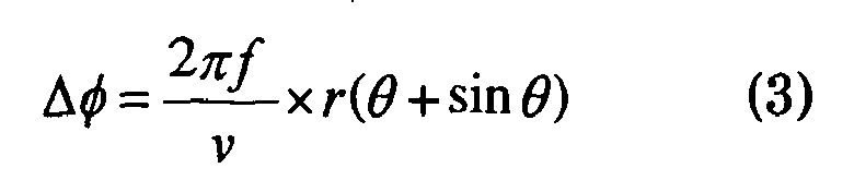
where Δφ represents an interaural intensity phase difference (IPD), ν sound velocity, ƒ a frequency, r is a value depending from aninteraural distance 2r and θ represents a direction of a sound source. - The relationship between a phase difference Δφ and a frequency ƒ of acoustic signals, which come from a direction of a sound source, is obtained with the equation (3) and shown in FIG.6.
- The
belief factor calculator 17 calculates a belief factor for IPD and IID, respectively. - Description is first given of "IPD belief factor". An IPD belief factor is obtained as a function of θ so as to indicate which direction a harmonic component ƒ k is likely to come from, which is included in a harmonic relationship (harmonic relationship CR41 or CL41, for example) corresponding to a speaker HMj. The IPD is fitted into a probability function.
- First, a hypothetical IPD (estimated value) for ƒ k is calculated with an equation (4).

- Δφ h (θ,ƒ k ) represents a hypothetical IPD (estimated value) with respect to a sound source lying in a direction θ for a kth harmonic component ƒ k . Thirty-seven hypothetical IPD's are, for example, calculated while a direction θ of a sound source is varied over a range of ± 90° at intervals of 5°. It may be alternatively possible to calculate at finer or rougher angle intervals.
- Next, a difference between Δφ h (θ,ƒ k ) and Δφ(ƒ k ) is calculated with an equation (5) and a summation is obtained for all the peak frequencies ƒ k . This difference, which represents a distance between a hypothesis and an input, tends to take a smaller value if θ lies closer to a direction of a speaker but a larger value if θ lies remoter from the direction of the speaker.

A belief factor B IPD (θ) is obtained by entering the resulting d(θ) in a probability function, the following equation (6).
where
- Description is given of "IID belief factor". An IID belief factor is obtained in the following manner. A summation of intensity differences included in a harmonic relationship corresponding to a speaker HMj is calculated with an equation (7).

where K represents number of harmonics included in a harmonic relationship, Δρ(ƒ k ) is an IID calculated by theIID calculator 15. - Introducing Table 1, a likelihood to be right, center or left associated with a sound direction is transformed into a belief factor. In this connection, Table 1 shows empirical values.
- When a hypothetical sound direction θ is equal to 40° and an intensity difference S has a positive sign, for example, a belief factor B IID (θ) is regarded as 0.35 according to the left-upper box of Table 1.
Table 1 θ 90° ~ 30° 30° ~ -30° -30° ~ -90° S + 0.35 0.5 0.65 - 0.65 0.5 0.35 - The
belief factor integrator 18 integrates an IPD belief factor B IPD (θ) and an IID belief factor B IID (θ) based on Dempster - Shafer theory with an equation (8), calculating an integrated belief factor B IPD+IID (θ). A θ which provides a largest B IPD+IID (θ) is considered to coincide with a direction of a speaker HMj, so that it is denoted as θ HMj in the description below.
- It may be alternatively possible to use a hypothesis by head related transfer function or a hypothesis by scattering theory instead of the hypothesis by auditory epipolar geometry.
- A hypothesis by head related transfer function is a phase difference and an intensity difference for sounds detected by microphones MR and ML, which are obtained from impulses generated in a surrounding environment of a robot.
- The hypothesis by head related transfer function is obtained in the following manner. The microphones MR and ML detect impulses, which are sent at appropriate intervals (5°, for example) over a range of -90° to 90°. A frequency analysis is conducted for each impulse so as to obtain a phase response and a magnitude response with respect to frequencies ƒ. A difference between phase responses and a difference between magnitude responses are calculated to provide a hypothesis by head related transfer function.
- The hypothesis by head related transfer function, which is calculated as described above, results in IPD shown in FIG.7A and IID shown in FIG.7B.
- When a head related transfer function is introduced, it is possible to obtain a relationship between IID and a frequency of a sound coming from a certain direction in addition to IPD. Therefore, a belief factor is calculated based on distance data d(θ), which has been generated for both IPD and IID. The method for generating hypothesis is the same for IPD and IID.
- Different from the method for generating a hypothesis with auditory epipolar geometry, a hypothesis by head related transfer function establishes a relationship between frequency ƒ and IPD for a signal, which is generated in each sound direction, by means of measurement in lieu of calculation. A d(θ), which is a distance between a hypothesis and an input, is directly calculated from actual measurement values shown in FIGS.7A and 7B, respectively.
- Scattering theory estimates both IPD and IID, taking into account waves scattered by an object, which scatters sounds, a head of a robot, for example. It is assumed here that a head of a robot is an object which has a main effect on the input of a microphone and the head is a sphere having a radius "a". It is also assumed that coordinates representative of the center of the head are an origin of a polar coordinate.
- When r 0 is a position of a point sound source and r is an observation point, a potential due to a direct sound at the observation point is defined by an equation (9).

where: - ƒ : frequency of point sound source
- ν : sound velocity
- R : distance between a point sound source and an observation point
- As shown in "J. J. Bowman, T.B.A. Senior, and P.L.E. Uslenghi: Electromagnetic and Acoustic Scattering by simple shapes, Hemisphere Publishing Co., 1987" and the like, a potential due to direct and scattering sounds is defined by an equation (10) while the observation point r lies on a surface of the head.

where
V s : potential due to scattering sound
P n : Legendre Function of the First Kind
h (1) n : Hunkel Function of the First Kind - When polar coordinates for MR and ML are (a,π/2,0) and (a,-π/2,0), respectively, potentials at these microphones are represented by equations (11) and (12), respectively.


- In this way, a phase difference IPDΔφ s (θ,ƒ) and an intensity difference IIDΔρ s (θ,ƒ) are calculated by the following equations (13) and (14), respectively.


- Replacing Δφ h (θ,ƒ k ) of the equation (4) with IPDΔφ s (θ,ƒ), a B IPD (θ) is calculated in the same process as that for auditory epipolar geometry.
- Namely, a difference between Δφ s (θ,ƒ k ) and Δφ(ƒ k ) is calculated and a sum d(θ) for all peaks ƒ k is then calculated, which is incorporated into the probability density function shown in equation (6) so as to obtain a belief factor B IPD (θ).
- As for IID, d(θ) and B IID (θ) are calculated in the similar method to that applied to IPD. More specifically speaking, in addition to replacing Δφ with Δρ, Δφ h (θ,ƒ k ) in the equation (4) is replaced with IPDΔρ s (θ,ƒ k ) in the equation (14). Then, a difference between Δρ s (θ,ƒ k ) and Δρ(ƒ k ) is calculated and a sum d(θ) for all peaks ƒ k is then calculated, which is incorporated into the probability density function shown in equation (6) so as to obtain a belief factor B IID (θ).
- If a sound direction is estimated based on the scattering theory, it is possible to generate a model representing a relationship between a sound direction and a phase difference as well as between a sound direction and an intensity difference, taking into account speeches scattering along the surface of a head of robot, for example an effect by a sound traveling round a rear side of the head. This leads to an increase in accuracy for estimation of a sound direction. When a sound source lies sideways with respect to the head, it is particularly possible to increase the accuracy for estimation of a sound direction by introducing the scattering theory, because the power of a sound reaching to a microphone is relatively great, which lies in an opposite direction of the sound source.
- The sound
source separation module 20 separates acoustic (speech) signals for a speaker HMj according to information on a localized sound direction and a spectrum (spectrum CR2, for example) provided by the soundsource localization module 10. Though there may be conventional methods applicable to separation of a sound source, beam forming, null forming, peak tracking, a directional microphone, Independent Component analysis (ICA) and the like, for example, description here is given of a method with an active direction-pass filter developed by the inventers of the present invention. - As a sound direction lies remoter from the front of a robot RB, it tends to be more difficult to expect accuracy for information on the sound direction, which is estimated through two microphones, in separating a sound source. In order to solve this problem, this embodiment employs active control so that a pass range is narrower for a sound source lying in the front direction but wider for a sound source lying remote from the front direction, thereby increasing accuracy for separating a sound source.
- More specifically speaking, the sound
source separation module 20 includes apass range function 21 and asubband selector 22, as shown in FIG.8. - As shown in FIG.9, the
pass range function 21 is a function of a sound direction and a pass range, which is in advance adjusted to have a greater pass range as a sound direction lies remoter from the front. The reason for this is that it is more difficult to expect accuracy for information on a sound direction as it lies remoter from the front (0°). - The
subband selector 22 selects a sub-band, which is estimated to come from a particular direction, out of respective frequencies (called "sub-band") of each of the spectrums CR2 and CL2. As shown in FIG.10, thesubband selector 22 calculates IPDΔφ(ƒ i ) and IIDΔρ(ƒ i ) (see an interaural phase difference C52 and an interaural intensity difference C62 in FIG.10) for sub-bands of a spectrum according to the equations (1) and (2), based on the right and left spectrums CR2 and CL2, which are generated by the soundsource localization module 10. - Determining a θ HMj , which is obtained by the sound
source localization module 10, to be a sound direction which should be retracted, thesubband selector 22 refers to thepass range function 21 so as to obtain a pass range δ(θ HMj ) corresponding to the θ HMj . Thesubband selector 22 calculates a maximum θ h and a minimum θ l according to the obtained pass range δ(θ HMj ) with the following equation (15). - A pass range B is shown in FIG.11 in the form of a plan view, for example.

- Next, estimation is conducted for IPD and IID corresponding to θ l and θ h . This estimation is carried out with a transfer function, which is prepared in advance by measurement or calculation. The transfer function is a function which correlates a frequency and IPD as well as a frequency and IID, respectively, with respect to a signal coming from a sound direction θ. As described above, epipolar geometry, a head related transfer function or scattering theory is applied to the transfer function. An estimated IPD is, for example, shown in FIG.10 as Δφ l (ƒ) and Δφ h (ƒ) in an interaural phase difference C53, and an estimated IID is, for example, shown in FIG.10 as Δρ l (ƒ) and Δρ h (ƒ) in an interaural intensity difference C63.
- Utilizing a transfer function of a robot RB, the
subband selector 22 selects a sub-band for a sound direction θ HMj according to a frequency ƒ i of the spectrum CR2 or CL2. Thesubband selector 22 selects a sub-band based on IPD if the frequency ƒ i is lower than a threshold frequency ƒ th , or based on IID if the frequency ƒ i is higher than the threshold frequency ƒ th . Thesubband selector 22 selects a sub-band which satisfies a conditional equation (16).
where ƒ th represents a threshold frequency, based on which one of IPD and IID is selected as a criterion for filtering. - According to this conditional equation, a subband of frequency ƒ i (an area with diagonal lines), in which IPD lies between Δφ l (ƒ) and Δφ h (ƒ), is selected for frequencies lower than the threshold frequency ƒ th in the interaural phase difference C53 shown in FIG.10. In contrast, a subband (an area with diagonal lines), in which IID lies between Δρ l (ƒ) and Δρ h (ƒ), is selected for frequencies higher than the threshold frequency ƒ th in the interaural intensity difference C63 shown in FIG.10. A spectrum containing selected sub-bands in this way is referred to as "extracted spectrum" in this specification.
- There is an alternative method, which introduces a directional microphone for separating a sound source, instead of the sound
source separation module 20 according to this embodiment described above. More specifically speaking, a microphone with narrow directivity is installed on a robot RB. If the face of the robot is so controlled that the directional microphone is turned to a sound direction θ HMj acquired by the soundsource localization module 10, it is possible to collect only speeches coming from this direction. - If there is only a single directional microphone, a problem may arise that collection of speeches is limited to a single person. However, it may be possible to allow simultaneous collection of speeches of a plurality of people if a plurality of directional microphones is arranged at regular intervals of a certain angle so that it is possible to selectively use speech signals sent by each directional microphone arranged for a sound direction.
- The
feature extractor 30 extracts features necessary for speech recognition from a speech spectrum, which is separated by the soundsource separation module 20, or an unseparated spectrum CR2 (or CL2). These spectrums are each referred to as "spectrum for recognition" when they are used for speech recognition. It is possible to use a linear spectrum as features of speech, Mel frequency spectrum or Mel-Frequency Cepstrum Coefficient (MFCC), which results from frequency analysis. In this embodiment, description is given of an example with MFCC. In this connection, when a linear spectrum is adopted, thefeature extractor 30 does not carry out any process. In the case of Mel frequency spectrum a cosine transformation (to be described later) is not carried out. - As shown in FIG.12A, the
feature extractor 30 includes alog spectrum converter 31, aMel frequency converter 32 and a discrete cosine transformation (DCT)module 33. - The
log spectrum converter 31 converts an amplitude of spectrum for speech recognition, which is selected by the subband selector 22 (see FIG.8), into a logarithm, providing a log spectrum. - The
Mel frequency converter 32 makes the log spectrum generated by thelog spectrum converter 31 pass through a bandpass filter of Mel frequency, providing a Mel frequency spectrum, whose frequency is converted to Mel scale. - The
DCT module 33 carries out a cosine transformation for the Mel frequency spectrum generated by theMel frequency converter 32. A coefficient obtained by this cosine transformation results in MFCC. - It may be possible to add a
masking module 34, which gives an index (0 to 1), within or after thefeature extractor 30 as shown in FIG.12B so that a spectrum subband is not considered to have reliable features when an input speech is deformed due to noise. - Description in detail is given of an example shown in FIG.12B. When a
feature extractor 30 includes amasking module 34, adictionary 59 possesses a time series spectrum corresponding to a word. Here, this time series spectrum is referred to as "word speech spectrum". - A word speech spectrum is acquired by a frequency analysis carried out for speeches resulting from a word uttered under a noise-free environment. When a spectrum for recognition is entered into the
feature extractor 30, a word speech spectrum for a word, which is estimated to exist in an input speech, is sorted out as an estimated speech spectrum from a dictionary. A criterion applied to the estimation here is that a speech spectrum having the most close time span as that of a spectrum for recognition is regarded as an expected speech spectrum. Undergoing thelog spectrum converter 31, theMel frequency converter 32 and theDCT module 33, the spectrum for recognition and the expected speech spectrum are each transformed into MFCCs. In the following descriptions, MFCCs of spectrum for recognition is referred to as "MFCCs for recognition" and MFCCs of expected speech spectrum as "expected MFCC". - The
masking module 34 calculates a difference between MFCCs for recognition and expected MFCCs, assigning zero to an MFCC, if the difference is greater than a threshold estimated beforehand but one if it is smaller than the threshold. Themasking module 34 sends the value as an index ω in addition to MFCCs for recognition to aspeech recognition module 50. - It may be possible to sort out one or more expected speech spectrums. It may be alternatively possible to adopt all word speech spectrums without sorting out. In this case, the masking
module 34 assigns indexes ω to all expected speech spectrums, sending them to thespeech recognition module 50. - When a directional microphone is used for sound source separation, an ordinary method of frequency analysis, such as an FFT and bandpass filter, is applied to a separated speech so as to obtain a spectrum.
- The acoustic
model composition module 40 composes an acoustic model adjusted to a localized sound direction based on direction-dependent acoustic models, which are stored in theacoustic model memory 49. - As shown in FIG.13, the acoustic
model composition module 40, which has an inverse discrete cosine transformation (IDCT)module 41, alinear spectrum converter 42, anexponential converter 43, aparameter composition module 44, alog spectrum converter 45, aMel frequency converter 46 and a discrete cosine transformation (DCT)module 47, composes an acoustic model for a direction θ by referring to direction-dependent acoustic models H(θ n ), which are stored in theacoustic model memory 49. - Direction dependent acoustic models H(θ n ), which are adjusted to respective directions θ n with respect to the front of a robot RB, are stored in the
acoustic model memory 49. A direction-dependent acoustic model H(θ n ) is trained on speech of a person uttered from a particular direction θ n by way of Hidden Markov Model (HMM). As shown in FIG.14, a direction-dependent acoustic model H(θ n ) employs a phoneme as a unit for recognition, storing a corresponding sub-model h(m,θ n ) for the phoneme. In this connection, it may be possible that other units for recognition such as monophone, PTM, biphone, triphone and the like are adopted for generating a sub-model. - If there are seven sub-models at regular intervals of 30° over a range -90° to 90° in terms of direction θ n and each sub-model is composed of 40 pieces of monophone, the number of sub-models h(m,θ n ) results in 7×40=280.
- A sub-model h(m,θ n ) has parameters such as number of states, a probability density distribution for each state and state transition probability. In this embodiment, the number of states for a phoneme is fixed to three: front (state 1), middle (state 2) and rear (state 3). Although a normal distribution is adopted in this embodiment, it may be alternatively possible to select a mixture model made of one or more other distributions in addition to a normal distribution for the probability density distribution. In this way, the
acoustic model memory 49 according to this embodiment is trained on a state transition probability P and parameters of a normal distribution, namely a mean µ and a standard deviation σ. - Description is given of steps for generating training data for a sub-model h(m,θ n ).
- Speech signals, which include particular phonemes, are applied to a robot RB by a speaker (not shown) in a direction, for which an acoustic model is intended to generate. The
feature extractor 30 converts the detected acoustic signals to MFCC, which thespeech recognition module 50 to be described later recognizes. In this way, a probability for a recognized speech signal is obtained for each phoneme. An acoustic model undergoes adaptive training, while a teaching signal indicative of a particular phoneme corresponding to a particular direction is given to the resulting probability. The acoustic model undergoes further training with phonemes and words of sufficient kinds (different speakers, for example) to learn a sub-model. - When a speech for training is given, it may be possible to give another speech as noise in a direction different from that, in which generation of an acoustic model is intended. In this case, the
speech separation module 20 separates only a speech, which lies in a direction intended for generating an acoustic model, and then thefeature retractor 30 converts the speech to MFCCs. In addition, if an acoustic model is intended for unspecified speakers, it may be possible for the acoustic model to be trained on their voices. In contrast, if an acoustic model is intended for specified speakers individually, it may be possible for the acoustic model to lean with each speaker. - The
IDCT module 41 to theexponential converter 43 restore an MFCC of probability density distribution to a linear spectrum. They carry out a reverse operation for a probability density distribution in contrast to thefeature extractor 30. - The
IDCT module 41 carries out inverse discrete cosine transformation for MFCC, which is possessed by a direction-dependent acoustic model H(θ n ) stored in theacoustic model memory 49, generating a Mel frequency spectrum. - The
linear spectrum converter 42 converts frequencies of the Mel frequency spectrum, which is generated by theIDCT module 41, to linear frequencies, generating a log spectrum. - The
exponential converter 43 carries out an exponential conversion for the intensity of the log spectrum, which is generated by thelinear spectrum converter 42, so as to generate a linear spectrum. The linear spectrum is obtained in the form of a probability density distribution of a mean µ and a standard deviation σ. - As shown in FIG.15, the
parameter composition module 44 multiplies each direction-dependent acoustic model H(θ n ) by a weight and makes a sum of the resulting products, composing an acoustic model H(θ HMj ) for a sound direction θ HMj . Sub-models lying in a direction-dependent acoustic model H(θ n ) are each converted to a probability density distribution of linear spectrum by theIDCT module 41, thelinear spectrum converter 42 and theexponential converter 43, having parameters such as means µ1nm , µ2nm , µ3nm , standard deviations σ 1nm ,σ2nm ,σ3nm and state transition probabilities P 11nm , P 12nm , P 22nm , P 23nm , P 33nm . Themodule 44 normalizes an acoustic model for a sound direction θ HMj by multiplying these parameters and weights, which are obtained beforehand by training and stored in theacoustic model memory 49. In other words, themodule 44 composes an acoustic model for a sound direction θ HMj by taking a linear summation of direction-dependent acoustic models H(θ n ). In this connection, it will be described later how a weight W nθHMj is introduced. - When sub-models lying in H(θ HMj ) are composed, a mean µ1θHMjm of the
state 1 is calculated by an equation (17).
- Means µ2θHMjm and µ3θHMjm can be calculated similarly.
- For composition of a standard deviation σ 1θHMjm of the
state 1, a covariance σ 1θHMjm 2 is calculated by an equation (18).
- Standard deviations σ 2θHMjm and σ 3θHMjm can be obtained similarly. It is possible to calculate a probability density distribution with the obtained µ and σ.
- Composition of a state transition probability P 11θHMjm for
state 1 is calculated by an equation (19).
- State transition probabilities P 12θHMjm , P 22θHMjm , P 23θHMjm and P 33θHMjm can be calculated similarly.
- Next, a probability density distribution is reconverted to MFCC by a
log converter 45 through aDCT module 47. Because thelog converter 45,Mel frequency converter 46 andDCT module 47 are similar to thelog converter 31,Mel frequency converter 32 andDCT converter 33, respectively, description in detail is not repeated. - When a probability density distribution is composed in the form of a mixture normal distribution instead of a single normal distribution, a probability density distribution ƒ1θHMjm (x) is calculated by an equation (20) instead of the calculation of the mean µ and standard deviation σ described above.

- Probability density distributions ƒ2θHMjm (x) and ƒ3θHMjm (x) can be calculated similarly.
- The
parameter composition module 44 has the acoustic model described above stored in theacoustic model memory 49. - In this connection, the
parameter composition module 44 carries out in real time such acoustic model composition while the automaticspeech recognition system 1 is in operation. - A weight W nθHMj is assigned to a direction-dependent acoustic model H(θ n ) when an acoustic model for a sound direction θ HMj is composed. It may be possible to adopt a common weight W nθHMj for all sub-models h(m,θ n ) or an individual weight W mnθHMj for each sub-model h(m,θ n ). Basically speaking, a function ƒ(θ), which defines a weight W nθ0 for a sound source lying in front of the robot RB, is prepared in advance. When an acoustic model is composed for a sound direction θ HMj , a corresponding function ƒ(θ) is obtained by shifting ƒ(θ) along a θ- axis by θ HMj (θ→θ-θ HMj ). A W nθHMj is determined by referring to the resulting function ƒ(θ).
- When ƒ(θ) is empirically generated, ƒ(θ) is described by the following equations with a constant "a", which is empirically obtained.


- Assuming the constant a =1.0, ƒ(θ) for a front sound source results in FIG.16A. FIG.16B shows ƒ(θ), which is shifted along the θ- axis by θ HMj .
- When ƒ(θ) is generated by training, training is carried out in the following manner, for example.
- W mnθ0 represents a weight applied to an arbitrary phoneme "m", which lies in the front. A trial is conducted with an acoustic model H(θ0), which is composed with a weight W mnθ0 that is appropriately selected as an initial value, so that the acoustic model H(θ0) recognizes a sequence of phonemes including a phoneme "m", [m m' m"] for example. More specifically speaking, this sequence of phonemes is given by a speaker, which is placed in the front and the trial is carried out. Though it is possible to select a single phoneme "m" as training data, a sequence of phonemes is adopted here, because it is possible to attain better results of training with the sequence of phonemes, which is a train of plural phonemes.
- FIG.17 exemplarily shows results of recognition. In the FIG.17, the result of recognition with the acoustic model H(θ0), which is composed with the initial value W mnθ0, is shown in the first row, and results of recognition with the acoustic model H(θ n ) are shown in the second row or below. For example, it is shown that the recognition result with an acoustic model H(θ90) was a sequence of phonemes [/x//y//z/] and the recognition result with an acoustic model H(θ0) was a sequence of phonemes [/x//y/m"].
- Seeing the first phoneme in FIG.17 after the first trail, when a corresponding phoneme is recognized for a direction within a range of θ = ±90° relative to the front, a weight W mnθ90 for a model representative of the direction is increased by Δd. Δd. is set to be 0.05, for example, which is empirically determined. In contrast, when no corresponding phoneme is recognized for a direction, a weight W mnθ0 for a model representative of the direction is decreased by Δd/(n-k). In this way, a weight for a direction-dependent model having produced a correct answer is increased, but one without a correct answer is decreased.
- Since H(θ n ) and H(θ90) each have a correct answer in the case of the example shown in FIG.17, corresponding weights W mnθ and W m90θ0 are increased by Δd, but other weights are decreased by 2Δd/(n-2).
- On the other hand, when there are no directions θ n , in which a phoneme coinciding with the first phoneme is recognized and there is a dominant direction-dependent acoustic model H(θ n ) having a larger weight relative to other models, a weight is decreased for only this model H(θ n ) by Δd and other weights are increased by kΔd/(n-k). Because the fact that any direction-dependent acoustic model failed recognition implies that a current distribution of weights is inappropriate, a reduction in weight is implemented for the direction, in which the current weight works dominantly.
- It is determined whether a weight is dominant or not by checking whether the weight is larger than a predetermined threshold (0.8 here, for example). If there are no dominant direction-dependent acoustic models H(θ n ), only the maximum weight is decreased by Δd and other weights for other direction-dependent acoustic models H(θ n ) are increased by Δd/(n-1).
- And the trial described above is repeated with the updated weights.
- When the recognition of the acoustic model H(θ90) results in a correct answer "m", the repetition is stopped, and recognition and training is moved to the next phoneme m' or training is stopped. When the training is stopped, the weight W mnθ90 obtained here will be ƒ(θ). When moved to the next phoneme m', a mean of weights W mnθ90, which result from training of all the phonemes, will be ƒ(θ).
- It may be alternatively possible to assign a weight W mnθHMj corresponding to each sub-model h(m,θ n ) to ƒ(θ) without taking a mean.
- When a given number of trials (0.5/Δd times, for example) does not allow the recognition result of an acoustic model H(θ HMj ) to be a correct answer, recognition of "m" is not successful for example, the trial is moved to training of a next phoneme m'. Weights are updated by the same value as the distribution of weight for a phoneme (m' for example), which is successfully recognized at last.
- It may be possible to prepare beforehand a common weight W nθHMj , which is used by all sub-models h(m,θ n ) included in H(θ n ) (see Table 2), or Table 3, which shows a weight W nθHMj corresponding to each sub-model h(m,θ n ), for an appropriate θ HMj . In this connection,
subscripts 1···m···M represent phonemes and 1···n···N directions, in Table 2 and Table 3.Table 2 H(θ 1) H(θ 2) ... H(θ n ) ... H(θ N ) h(1,θ 1) h(1,θ 2) ... h(1,θ n ) ... h(1,θ N ) · · · · · · ... · ... · · · · · h(m,θ 1) h(m,θ 2) ... h(m,θ n ) ... h(m,θ N ) · · · · · · ... · ... · · · · · h(M,θ 1) h(M,θ 2) ... h(M,θ n ) ... h(M,θ N ) Table 3 W 1 W 2 ... W n ... W N W 11 W 12 ... W 1n ... W 1N · · · · · · ... · ... · · · · · W m1 W m2 ... W mn ... W mN · · · · · · ... · ... · · · · · W M1 W M2 ... W Mn ... W MN - The weights obtained by training described above are stored in the
acoustic model memory 49. - Using an acoustic model H(θ HMj ) composed for a sound direction θ HMj , the
speech recognition module 50 recognizes features, which are extracted from separated speech of a speaker HMj or an input speech, generating character information. Subsequently, themodule 50 recognizes the speech referring to thedictionary 59 to provide results of recognition. Since this method of speech recognition is based on an ordinary technique with Hidden Markov Model, description in detail would be omitted. - When a masking module, which adds an index ω indicating a belief factor to each sub-band of MFCC, is disposed inside or after the
feature extractor 30, thespeech recognition module 50 carries out recognition after applying a process shown by an equation (21) to a received feature.
- x r
- : feature to be used for speech recognition
- x
- : MFCC
- i
- : component of MFCC
- x n
- : unreliable component of x
- Using the obtained output probability and state transition probability, the
module 50 performs recognition in the same manner as that of general Hidden Markov Model. - Description is given of operation carried out by an automatic
speech recognition system 1 configured as described above. - As shown in FIG.1, speeches of a plurality of speakers HMj (see FIG.3) enter microphones MR and ML of a robot RB.
- Sound directions of acoustic signals detected by the microphones MR and ML are localized by a sound
source localization module 10. As described above, themodule 10 calculates a belief factor with hypothesis by auditory epipolar geometry after conducting frequency analysis, peak extraction, extraction of harmonic relationship and calculation of IPD and IID. Integrating IPD and IID, themodule 10 subsequently regards the most probable θ HMj as a sound direction (see FIG.2). - Next, a sound
source separation module 20 separates a sound corresponding to a sound direction θ HMj . Sound separation is carried out in the following manner. First, themodule 20 obtains upper limits Δφ h (ƒ) and Δρ h (ƒ), and lower limits Δφ l (ƒ) and Δρ l (ƒ) for IPD and IID for a sound direction θ HMj with a pass range function. Themodule 20 selects sub-bands (selected spectrum) which are estimated to be a spectrum for the sound direction θ HMj by introducing the equation (16) described above and these upper limits and lower limits. Subsequently, themodule 20 converts the spectrum of the selected sub-bands by reverse FFT, transforming the spectrum into speech signals. - A
feature extractor 30 converts the selected spectrum separated by the soundsource separation module 20 into MFCC by alog spectrum converter 31, aMel frequency converter 32 and aDCT module 33. - On the other hand, an acoustic
model composition module 40 composes an acoustic model, which is considered appropriate for a sound direction θ HMj receiving a direction-dependent acoustic model H(θ n ) stored in anacoustic model memory 49 and a sound direction θ HMj localized by the soundsource localization module 10. - The acoustic
model composition module 40, which has anIDCT module 41, alinear spectrum converter 42 and anexponential converter 43, converts the direction-dependent acoustic model H(θ n ) into a linear spectrum. Aparameter composition module 44 composes an acoustic model H(θ HMj ) for a sound direction θ HMj by taking an inner product of a direction-dependent acoustic model H(θ n ) and a weight W nθHMj for a sound direction θ HMj , which themodule 44 reads out from theacoustic model memory 49. Themodule 40, which has alog spectrum converter 45, aMel frequency converter 46 and aDCT module 47, converts this acoustic model H(θ HMj ) in the form of a linear spectrum to an acoustic model H(θ HMj ) in the form of MFCC. - Next, a
speech recognition module 50 carries out speech recognition with Hidden Markov Model, using the acoustic model H(θ HMj ) composed by the acousticmodel composition module 40. - Table 4 shows an example resulting from the method described above.
Table 4 Conventional method This invention Direction of acoustic model -90° -60° -30° 0° 30° 60° 90° 40° Recognition rate of isolated word 20% 20% 38% 42% 60% 59% 50% 78% - As shown in Table 4, when direction-dependent acoustic models were prepared for a range of -90° to 90° at regular intervals of 30° and speech recognition was carried out for isolated words with each acoustic model in a direction of 40° (conventional method), the best recognition rate was 60%, which was obtained by a direction-dependent acoustic model for a direction of 30°. In contrast, recognition of isolated words with an acoustic model for a direction of 40°, which was composed with a method according to this embodiment, attained high recognition rate of 78%. Because it is possible for an automatic
speech recognition system 1 according to this embodiment to compose an appropriate acoustic model each time speech is uttered in an arbitrary direction, high recognition rate can be realized. In addition, it is possible for thesystem 1, which is able to recognize speech uttered in an arbitrary direction, to implement speech recognition with high recognition rate while a sound source or a moving object (robot RB) is moving. - Because it may be alternatively possible to prepare a small number of direction-dependent acoustic models, at intervals of 60° or 30° in terms of sound direction, for example, it may be possible to decrease costs necessary for training of the acoustic models.
- Because it is sufficient to carry out speech recognition for a single composed acoustic model, parallel processing is not required so as to carry out speech recognition for acoustic models representative of plural directions, which may lead to a reduction in calculation cost. Therefore, the automatic
speech recognition system 1 according to this embodiment is appropriate for real-time processing and embedded use. - The present invention is not limited to the first embodiment, which has been described so far, but it may be possible to implement alternatives such as modified embodiments described below.
- A second embodiment of the present invention has a sound
source localization module 110, which localizes a sound direction with a peak of correlation, instead of the soundsource localization module 10 of the first embodiment. Because the second embodiment is similar to the first embodiment except for this difference, description would not be repeated for other modules. - As shown in FIG.18, the sound
source localization module 110 includes aframe segmentation module 111, acorrelation calculator 112, a peak extractor 113 and adirection estimator 114. - The
frame segmentation module 111 segments acoustic signals, which have entered right and left microphones MR and ML, so as to generate segmental acoustic signals having a given time length, 100msec for example. Segmentation process is carried out at appropriate time intervals, 30msec for example. - The
correlation calculator 112 calculates a correlation by an equation (22) for the acoustic signals of the right and left microphones MR and ML, which have been segmented by theframe segmentation module 111.
where: - CC(T): correlation between x L (t) and x R (t)
- T: frame length
- x L (t): input signal from the microphone L segmented by frame length T
- x R (t): input signal from the microphone R segmented by frame length T
- The peak extractor 113 extracts peaks from the resulting correlations. Peaks are selected in order of peak height while their number is adjusted to the number of sound sources when it is known in advance. When the number of sound sources is not known, on the other hand, it may be possible to extracts all peaks exceeding a predetermined threshold or a predetermined number of peaks in order of peak height.
- Receiving the obtained peaks, the
direction estimator 114 calculates a difference of distance "d" shown in FIG.19 by multiplying an arrival time difference D of acoustic signals entering the right and left microphones MR and ML by sound velocity "v". Thedirection estimator 114 then generates a sound direction θ HMj by the following equation.
- The sound
source localization module 110, which introduces the correlation described above, is also able to estimate a sound direction θ HMj . It is possible to increase a recognition rate with an acoustic model appropriate for the sound direction θ HMj , which is composed by an acousticmodel composition module 40 described above. - A third embodiment has an additional function that a sound source localization module performs speech recognition while it is checking if acoustic signals come from a same sound source. Description would not be repeated for modules which are similar to those described in the first embodiment, bearing the same symbols.
- As shown in FIG.20, an automatic
speech recognition system 100 according to the third embodiment has an additional module, astream tracking module 60, compared with the automaticspeech recognition system 1 according to the first embodiment. Receiving a sound direction localized by a soundsource localization module 10, thestream tracking module 60 tracks a sound source so that it checks if acoustic signals continue coming from the same sound source. If it succeeds in confirmation, thestream tracking module 60 sends the sound direction to a soundsource separation module 20. - As shown in FIG.21, the
stream tracking module 60 has a sounddirection history memory 61, apredictor 62 and acomparator 63. - The sound
direction history memory 61 stores time, a direction and a pitch (a fundamental frequency ƒ0 which a harmonic relationship of the sound source possesses) of a sound source at this time, in the correlated form. - The
predicator 62 reads out the sound direction history of the sound source, which has being tracked so far, from the sounddirection history memory 61. Subsequently, thepredicator 62 predicts a stream feature vector (θ HMj ,ƒ0) with a Kalman filter and the like, which is made of a sound direction θ HMj and a fundamental frequency ƒ0 at current time t1, sending the stream feature vector (θ HMj , ƒ0) to thecomparator 63. - The
comparator 63 receives from the sound source localization module 10 a sound direction θ HMj of each speaker HMj and a fundamental frequency ƒ0 of the sound source at current time t1, which has been localized by the soundsource localization module 10. Thecomparator 63 compares a predicted stream feature vector (θ HMj ,ƒ0), which is sent by thepredicator 62, and a stream feature vector (θ HMj ,ƒ0) resulting from a sound direction and a pitch, which are localized by the soundsource localization module 10. If a resulting difference (distance) is less than a predetermined threshold, thecomparator 63 sends the sound direction θ HMj to the sound source separation module. Thecomparator 63 also makes the stream feature vector (θ HMj ,ƒ0) store in the sounddirection history memory 61. - If the difference (distance) is more than the predetermined threshold, the
comparator 63 does not send the localized sound direction θ HMj to the soundsource separation module 20, so that speech recognition is not carried out. In this connection, it may be alternatively possible for thecomparator 63 to send data, which indicates whether or not a sound source can be tracked, to the soundsource separation module 20 in addition to a sound direction θ HMj . - It may be alternatively possible to use only a sound direction θ HMj without a fundamental frequency ƒ0 in performing prediction.
- In the automatic
speech recognition system 100, a sound direction which is localized by the soundsource localization module 10 and a pitch enter thestream tracking module 60 described above. In thestream tracking module 60, thepredicator 62 reads out a sound direction history stored in the sounddirection history memory 61, predicting a stream feature vector (θ HMj ,ƒ0) at a current time t1. Thecomparator 63 compares a stream feature vector (θ HMj ,ƒ0) which is predicted by thepredicator 62 and a stream feature vector (θ HMj ,ƒ0) resulting from values, which are sent by the soundsource localization module 10. If the difference (distance) is less than a predetermined threshold, thecomparator 63 sends a sound direction to the soundsource separation module 20. - The sound
source separation module 20 separates sound sources based on spectrum data, which is sent by the soundsource localization module 10, and sound direction θ HMj data, which is sent by thestream tracking module 60, in the similar manner as that of the first embodiment. Afeature extractor 30, an acousticmodel composition module 40 and aspeech recognition module 50 carry out processes in the similar manner as that of the first embodiment. - Because the automatic
speech recognition system 100 according to this embodiment carries out speech recognition as a result of checking if a sound source can be tracked, it is able to keep carrying recognition for a speech uttered by the same sound source even if the sound source is moving, which will lead to a reduction in probability for false recognition. The automaticspeech recognition system 100 is beneficial for a situation where there is a plurality of moving sound sources, which intersect each other. - In addition, the automatic
speech recognition system 100, which not only stores but also predicts sound directions, is able to decrease an amount of processing if searching for a sound source is limited to a certain area corresponding to a particular sound direction. - While the embodiments of the present invention have been described, the present invention is not limited to these embodiments, but can be implemented with various changes and modifications.
- One example is an automatic
speech recognition system 1, which includes a camera, a well-known image recognition system and a speaker identification module, which recognizes a face of a speaker and identifies the speaker referring to its database. When thesystem 1 possesses direction-dependent acoustic models for each speaker, it is possible to compose an acoustic model appropriate for each speaker, which enables higher recognition rate. It may be possible to adopt an alternative, which introduces speeches of speakers registered in advance in the form of vector by vector quantization (VQ). Thesystem 1 compares the registered speeches and a speech in the form of vector which the soundsource separation module 20 separates, outputting the resulting speaker having the smallest distance.
Claims (8)
- An automatic speech recognition system, which recognizes speeches in acoustic signals detected by a plurality of microphones as character information, the system comprising:a sound source localization module which localizes a sound direction corresponding to a specified speaker based on the acoustic signals detected by the plurality of microphones;a feature extractor which extracts features of speech signals contained in one or more pieces of information detected by the plurality of microphones;an acoustic model memory which stores direction-dependent acoustic models that are adjusted to a plurality of directions at intervals;an acoustic model composition module which composes an acoustic model adjusted to the sound direction, which is localized by the sound source localization module, based on the direction-dependent acoustic models in the acoustic model memory, the acoustic model composition module storing the acoustic model in the acoustic model memory; anda speech recognition module which recognizes the features extracted by the feature extractor as character information using the acoustic model composed by the acoustic model composition module.
- An automatic speech recognition system, which recognizes speeches of a specified speaker in acoustic signals detected by a plurality of microphones as character information, the system comprising:a sound source localization module which localizes a sound direction corresponding to the specified speaker based on the acoustic signals detected by the plurality of microphones;a sound source separation module which separates speech signals of the specified speaker from the acoustic signals based on the sound direction localized by the sound source localization modulea feature extractor which extracts features of the speech signals separated by the sound source separation module;an acoustic model memory which stores direction-dependent acoustic models that are adjusted to a plurality of directions at intervals;an acoustic model composition module which composes an acoustic model adjusted to the sound direction, which is localized by the sound source localization module, based on the direction-dependent acoustic models in the acoustic model memory, the acoustic model composition module storing the acoustic model in the acoustic model memory; anda speech recognition module which recognizes the features extracted by the feature extractor as character information using the acoustic model composed by the acoustic model composition module.
- A system according to claim 1 or 2, wherein the sound source localization module is configured to execute a process comprising:performing a frequency analysis for the acoustic signals detected by the microphones to extract harmonic relationships;acquiring an intensity difference and a phase difference for the harmonic relationships extracted through the plurality of microphones;acquiring belief factors for a sound direction based on the intensity difference and the phase difference, respectively; anddetermining a most probable sound direction.
- A system according to any one of claims 1 to 3, wherein the sound source localization module employs scattering theory that generates a model for an acoustic signal, which scatters on a surface of a member to which the microphones are attached, according to a sound direction so as to specify the sound direction for the speaker with the intensity difference and the phase difference detected from the plurality of microphones.
- A system according to any one of claims 2 to 4, wherein the sound source separation module employs an active direction-pass filter so as to separate speeches, the filter being configured to execute a process comprising:separating speeches by a narrower directional band when a sound direction, which is localized by the sound source localization module, lies close to a front, which is defined by an arrangement of the plurality of microphones; andseparating speeches by a wider directional band when the sound direction lies apart from the front.
- A system according to any one of claims 1 to 5, wherein the acoustic model composition module is configured to compose an acoustic model for the sound direction by applying weighted linear summation to the direction-dependent acoustic models in the acoustic model memory, and weights introduced into the linear summation are determined by training.
- A system according to any one of claims 1 to 6, further comprising a speaker identification module,
wherein the acoustic model memory possesses the direction-dependent acoustic models for respective speakers, and
wherein the acoustic model composition module is configured to execute a process comprising:referring to direction-dependent acoustic models of a speaker who is identified by the speaker identifying module and to a sound direction localized by the sound source localization module;composing an acoustic model for the sound direction based on the direction-dependent acoustic models in the acoustic model memory; andstoring the acoustic model in the acoustic model memory. - An automatic speech recognition system, which recognizes speeches of a specified speaker in acoustic signals detected by a plurality of microphones as character information, the system comprising:a sound source localization module which localizes a sound direction corresponding to the specified speaker based on the acoustic signals detected by the plurality of microphones;a stream tracking module which stores the sound direction localized by the sound source localization module so as to estimate a direction in which the specified speaker is moving, the stream tracking module estimating a current position of the speaker according to the estimated direction;a sound source separation module which separates speech signals of the specified speaker from the acoustic signals based on a sound direction, which is determined by the current position of the speaker estimated by the stream tracking module;a feature extractor which extracts features of the speech signals separated by the sound source separation module;an acoustic model memory which stores direction-dependent acoustic models that are adjusted to a plurality of directions at intervals;an acoustic model composition module which composes an acoustic model adjusted to the sound direction, which is localized by the sound source localization module, based on the direction-dependent acoustic models in the acoustic model memory, the acoustic model composition module storing the acoustic model in the acoustic model memory; anda speech recognition module which recognizes the features extracted by the feature extractor as character information using the acoustic model composed by the acoustic model composition module.
Applications Claiming Priority (2)
| Application Number | Priority Date | Filing Date | Title |
|---|---|---|---|
| JP2003383072 | 2003-11-12 | ||
| PCT/JP2004/016883 WO2005048239A1 (en) | 2003-11-12 | 2004-11-12 | Speech recognition device |
Publications (3)
| Publication Number | Publication Date |
|---|---|
| EP1691344A1 true EP1691344A1 (en) | 2006-08-16 |
| EP1691344A4 EP1691344A4 (en) | 2008-04-02 |
| EP1691344B1 EP1691344B1 (en) | 2009-06-24 |
Family
ID=34587281
Family Applications (1)
| Application Number | Title | Priority Date | Filing Date |
|---|---|---|---|
| EP04818533A Expired - Fee Related EP1691344B1 (en) | 2003-11-12 | 2004-11-12 | Speech recognition system |
Country Status (5)
| Country | Link |
|---|---|
| US (1) | US20090018828A1 (en) |
| EP (1) | EP1691344B1 (en) |
| JP (1) | JP4516527B2 (en) |
| DE (1) | DE602004021716D1 (en) |
| WO (1) | WO2005048239A1 (en) |
Cited By (10)
| Publication number | Priority date | Publication date | Assignee | Title |
|---|---|---|---|---|
| RU2463674C2 (en) * | 2007-03-02 | 2012-10-10 | Панасоник Корпорэйшн | Encoding device and encoding method |
| CN102893327A (en) * | 2010-03-19 | 2013-01-23 | 数字标记公司 | Intuitive computing methods and systems |
| WO2014022148A1 (en) * | 2012-08-01 | 2014-02-06 | Google Inc. | Speech recognition models based on location indicia |
| CN105005027A (en) * | 2015-08-05 | 2015-10-28 | 张亚光 | System for positioning target object in regional scope |
| CN106104674A (en) * | 2014-03-24 | 2016-11-09 | 微软技术许可有限责任公司 | Mixing voice identification |
| CN108352159A (en) * | 2015-11-02 | 2018-07-31 | 三星电子株式会社 | The electronic equipment and method of voice for identification |
| CN109298642A (en) * | 2018-09-20 | 2019-02-01 | 三星电子(中国)研发中心 | The method and device being monitored using intelligent sound box |
| CN110495185A (en) * | 2018-03-09 | 2019-11-22 | 深圳市汇顶科技股份有限公司 | Audio signal processing method and device |
| EP3739415A4 (en) * | 2018-01-09 | 2021-03-03 | Sony Corporation | Information processing device, information processing method and program |
| US11049094B2 (en) | 2014-02-11 | 2021-06-29 | Digimarc Corporation | Methods and arrangements for device to device communication |
Families Citing this family (289)
| Publication number | Priority date | Publication date | Assignee | Title |
|---|---|---|---|---|
| US8645137B2 (en) | 2000-03-16 | 2014-02-04 | Apple Inc. | Fast, language-independent method for user authentication by voice |
| DE602005008005D1 (en) * | 2005-02-23 | 2008-08-21 | Harman Becker Automotive Sys | Speech recognition system in a motor vehicle |
| US8677377B2 (en) | 2005-09-08 | 2014-03-18 | Apple Inc. | Method and apparatus for building an intelligent automated assistant |
| US7697827B2 (en) | 2005-10-17 | 2010-04-13 | Konicek Jeffrey C | User-friendlier interfaces for a camera |
| JP4784366B2 (en) * | 2006-03-28 | 2011-10-05 | パナソニック電工株式会社 | Voice control device |
| JP2007318438A (en) * | 2006-05-25 | 2007-12-06 | Yamaha Corp | Voice state data generating device, voice state visualizing device, voice state data editing device, voice data reproducing device, and voice communication system |
| US9318108B2 (en) | 2010-01-18 | 2016-04-19 | Apple Inc. | Intelligent automated assistant |
| US8977255B2 (en) | 2007-04-03 | 2015-03-10 | Apple Inc. | Method and system for operating a multi-function portable electronic device using voice-activation |
| JP4877112B2 (en) * | 2007-07-12 | 2012-02-15 | ヤマハ株式会社 | Voice processing apparatus and program |
| US10002189B2 (en) | 2007-12-20 | 2018-06-19 | Apple Inc. | Method and apparatus for searching using an active ontology |
| US9330720B2 (en) | 2008-01-03 | 2016-05-03 | Apple Inc. | Methods and apparatus for altering audio output signals |
| US8532802B1 (en) * | 2008-01-18 | 2013-09-10 | Adobe Systems Incorporated | Graphic phase shifter |
| US8996376B2 (en) | 2008-04-05 | 2015-03-31 | Apple Inc. | Intelligent text-to-speech conversion |
| US10496753B2 (en) | 2010-01-18 | 2019-12-03 | Apple Inc. | Automatically adapting user interfaces for hands-free interaction |
| US20100030549A1 (en) | 2008-07-31 | 2010-02-04 | Lee Michael M | Mobile device having human language translation capability with positional feedback |
| KR101178801B1 (en) * | 2008-12-09 | 2012-08-31 | 한국전자통신연구원 | Apparatus and method for speech recognition by using source separation and source identification |
| US8676904B2 (en) | 2008-10-02 | 2014-03-18 | Apple Inc. | Electronic devices with voice command and contextual data processing capabilities |
| WO2010067118A1 (en) | 2008-12-11 | 2010-06-17 | Novauris Technologies Limited | Speech recognition involving a mobile device |
| US10241752B2 (en) | 2011-09-30 | 2019-03-26 | Apple Inc. | Interface for a virtual digital assistant |
| US20120309363A1 (en) | 2011-06-03 | 2012-12-06 | Apple Inc. | Triggering notifications associated with tasks items that represent tasks to perform |
| US9858925B2 (en) | 2009-06-05 | 2018-01-02 | Apple Inc. | Using context information to facilitate processing of commands in a virtual assistant |
| US10241644B2 (en) | 2011-06-03 | 2019-03-26 | Apple Inc. | Actionable reminder entries |
| US9431006B2 (en) | 2009-07-02 | 2016-08-30 | Apple Inc. | Methods and apparatuses for automatic speech recognition |
| US8175617B2 (en) | 2009-10-28 | 2012-05-08 | Digimarc Corporation | Sensor-based mobile search, related methods and systems |
| CN102483918B (en) * | 2009-11-06 | 2014-08-20 | 株式会社东芝 | Voice recognition device |
| US20110125497A1 (en) * | 2009-11-20 | 2011-05-26 | Takahiro Unno | Method and System for Voice Activity Detection |
| US9838784B2 (en) | 2009-12-02 | 2017-12-05 | Knowles Electronics, Llc | Directional audio capture |
| US8560309B2 (en) * | 2009-12-29 | 2013-10-15 | Apple Inc. | Remote conferencing center |
| JP5408621B2 (en) * | 2010-01-13 | 2014-02-05 | 株式会社日立製作所 | Sound source search apparatus and sound source search method |
| US10553209B2 (en) | 2010-01-18 | 2020-02-04 | Apple Inc. | Systems and methods for hands-free notification summaries |
| US10705794B2 (en) | 2010-01-18 | 2020-07-07 | Apple Inc. | Automatically adapting user interfaces for hands-free interaction |
| US10276170B2 (en) | 2010-01-18 | 2019-04-30 | Apple Inc. | Intelligent automated assistant |
| US10679605B2 (en) | 2010-01-18 | 2020-06-09 | Apple Inc. | Hands-free list-reading by intelligent automated assistant |
| US8676581B2 (en) * | 2010-01-22 | 2014-03-18 | Microsoft Corporation | Speech recognition analysis via identification information |
| US8718290B2 (en) | 2010-01-26 | 2014-05-06 | Audience, Inc. | Adaptive noise reduction using level cues |
| US8682667B2 (en) | 2010-02-25 | 2014-03-25 | Apple Inc. | User profiling for selecting user specific voice input processing information |
| US9378754B1 (en) | 2010-04-28 | 2016-06-28 | Knowles Electronics, Llc | Adaptive spatial classifier for multi-microphone systems |
| KR101750338B1 (en) * | 2010-09-13 | 2017-06-23 | 삼성전자주식회사 | Method and apparatus for microphone Beamforming |
| US10762293B2 (en) | 2010-12-22 | 2020-09-01 | Apple Inc. | Using parts-of-speech tagging and named entity recognition for spelling correction |
| KR101791907B1 (en) * | 2011-01-04 | 2017-11-02 | 삼성전자주식회사 | Acoustic processing apparatus and method based on position information |
| US9047867B2 (en) * | 2011-02-21 | 2015-06-02 | Adobe Systems Incorporated | Systems and methods for concurrent signal recognition |
| US9262612B2 (en) | 2011-03-21 | 2016-02-16 | Apple Inc. | Device access using voice authentication |
| US10057736B2 (en) | 2011-06-03 | 2018-08-21 | Apple Inc. | Active transport based notifications |
| WO2013007070A1 (en) * | 2011-07-08 | 2013-01-17 | 歌尔声学股份有限公司 | Method and device for suppressing residual echo |
| US9435873B2 (en) | 2011-07-14 | 2016-09-06 | Microsoft Technology Licensing, Llc | Sound source localization using phase spectrum |
| US8994660B2 (en) | 2011-08-29 | 2015-03-31 | Apple Inc. | Text correction processing |
| US9966088B2 (en) * | 2011-09-23 | 2018-05-08 | Adobe Systems Incorporated | Online source separation |
| US8879761B2 (en) | 2011-11-22 | 2014-11-04 | Apple Inc. | Orientation-based audio |
| BR112014015844A8 (en) * | 2011-12-26 | 2017-07-04 | Intel Corp | determining vehicle-based occupant audio and visual inputs |
| US10134385B2 (en) | 2012-03-02 | 2018-11-20 | Apple Inc. | Systems and methods for name pronunciation |
| US9483461B2 (en) | 2012-03-06 | 2016-11-01 | Apple Inc. | Handling speech synthesis of content for multiple languages |
| US9280610B2 (en) | 2012-05-14 | 2016-03-08 | Apple Inc. | Crowd sourcing information to fulfill user requests |
| US10417037B2 (en) | 2012-05-15 | 2019-09-17 | Apple Inc. | Systems and methods for integrating third party services with a digital assistant |
| US9881616B2 (en) * | 2012-06-06 | 2018-01-30 | Qualcomm Incorporated | Method and systems having improved speech recognition |
| US9721563B2 (en) | 2012-06-08 | 2017-08-01 | Apple Inc. | Name recognition system |
| US9495129B2 (en) | 2012-06-29 | 2016-11-15 | Apple Inc. | Device, method, and user interface for voice-activated navigation and browsing of a document |
| US9576574B2 (en) | 2012-09-10 | 2017-02-21 | Apple Inc. | Context-sensitive handling of interruptions by intelligent digital assistant |
| US9547647B2 (en) | 2012-09-19 | 2017-01-17 | Apple Inc. | Voice-based media searching |
| CN113470640B (en) | 2013-02-07 | 2022-04-26 | 苹果公司 | Voice trigger of digital assistant |
| US9368114B2 (en) | 2013-03-14 | 2016-06-14 | Apple Inc. | Context-sensitive handling of interruptions |
| WO2014144949A2 (en) | 2013-03-15 | 2014-09-18 | Apple Inc. | Training an at least partial voice command system |
| WO2014144579A1 (en) | 2013-03-15 | 2014-09-18 | Apple Inc. | System and method for updating an adaptive speech recognition model |
| US9582608B2 (en) | 2013-06-07 | 2017-02-28 | Apple Inc. | Unified ranking with entropy-weighted information for phrase-based semantic auto-completion |
| WO2014197334A2 (en) | 2013-06-07 | 2014-12-11 | Apple Inc. | System and method for user-specified pronunciation of words for speech synthesis and recognition |
| WO2014197336A1 (en) | 2013-06-07 | 2014-12-11 | Apple Inc. | System and method for detecting errors in interactions with a voice-based digital assistant |
| WO2014197335A1 (en) | 2013-06-08 | 2014-12-11 | Apple Inc. | Interpreting and acting upon commands that involve sharing information with remote devices |
| WO2014200728A1 (en) | 2013-06-09 | 2014-12-18 | Apple Inc. | Device, method, and graphical user interface for enabling conversation persistence across two or more instances of a digital assistant |
| US10176167B2 (en) | 2013-06-09 | 2019-01-08 | Apple Inc. | System and method for inferring user intent from speech inputs |
| AU2014278595B2 (en) | 2013-06-13 | 2017-04-06 | Apple Inc. | System and method for emergency calls initiated by voice command |
| US9536540B2 (en) | 2013-07-19 | 2017-01-03 | Knowles Electronics, Llc | Speech signal separation and synthesis based on auditory scene analysis and speech modeling |
| WO2015020942A1 (en) | 2013-08-06 | 2015-02-12 | Apple Inc. | Auto-activating smart responses based on activities from remote devices |
| WO2015029296A1 (en) * | 2013-08-29 | 2015-03-05 | パナソニック インテレクチュアル プロパティ コーポレーション オブ アメリカ | Speech recognition method and speech recognition device |
| JP6148163B2 (en) * | 2013-11-29 | 2017-06-14 | 本田技研工業株式会社 | Conversation support device, method for controlling conversation support device, and program for conversation support device |
| US10296160B2 (en) | 2013-12-06 | 2019-05-21 | Apple Inc. | Method for extracting salient dialog usage from live data |
| WO2015130273A1 (en) * | 2014-02-26 | 2015-09-03 | Empire Technology Development Llc | Presence-based device mode modification |
| US9620105B2 (en) | 2014-05-15 | 2017-04-11 | Apple Inc. | Analyzing audio input for efficient speech and music recognition |
| US10592095B2 (en) | 2014-05-23 | 2020-03-17 | Apple Inc. | Instantaneous speaking of content on touch devices |
| US9502031B2 (en) | 2014-05-27 | 2016-11-22 | Apple Inc. | Method for supporting dynamic grammars in WFST-based ASR |
| EP3480811A1 (en) | 2014-05-30 | 2019-05-08 | Apple Inc. | Multi-command single utterance input method |
| US9715875B2 (en) | 2014-05-30 | 2017-07-25 | Apple Inc. | Reducing the need for manual start/end-pointing and trigger phrases |
| US9633004B2 (en) | 2014-05-30 | 2017-04-25 | Apple Inc. | Better resolution when referencing to concepts |
| US9734193B2 (en) | 2014-05-30 | 2017-08-15 | Apple Inc. | Determining domain salience ranking from ambiguous words in natural speech |
| US9785630B2 (en) | 2014-05-30 | 2017-10-10 | Apple Inc. | Text prediction using combined word N-gram and unigram language models |
| US10289433B2 (en) | 2014-05-30 | 2019-05-14 | Apple Inc. | Domain specific language for encoding assistant dialog |
| US9430463B2 (en) | 2014-05-30 | 2016-08-30 | Apple Inc. | Exemplar-based natural language processing |
| US10078631B2 (en) | 2014-05-30 | 2018-09-18 | Apple Inc. | Entropy-guided text prediction using combined word and character n-gram language models |
| US10170123B2 (en) | 2014-05-30 | 2019-01-01 | Apple Inc. | Intelligent assistant for home automation |
| US9842101B2 (en) | 2014-05-30 | 2017-12-12 | Apple Inc. | Predictive conversion of language input |
| US9760559B2 (en) | 2014-05-30 | 2017-09-12 | Apple Inc. | Predictive text input |
| US9338493B2 (en) | 2014-06-30 | 2016-05-10 | Apple Inc. | Intelligent automated assistant for TV user interactions |
| US10659851B2 (en) | 2014-06-30 | 2020-05-19 | Apple Inc. | Real-time digital assistant knowledge updates |
| US9817634B2 (en) * | 2014-07-21 | 2017-11-14 | Intel Corporation | Distinguishing speech from multiple users in a computer interaction |
| US10446141B2 (en) | 2014-08-28 | 2019-10-15 | Apple Inc. | Automatic speech recognition based on user feedback |
| WO2016033269A1 (en) * | 2014-08-28 | 2016-03-03 | Analog Devices, Inc. | Audio processing using an intelligent microphone |
| US9818400B2 (en) | 2014-09-11 | 2017-11-14 | Apple Inc. | Method and apparatus for discovering trending terms in speech requests |
| US10789041B2 (en) | 2014-09-12 | 2020-09-29 | Apple Inc. | Dynamic thresholds for always listening speech trigger |
| DE112015004185T5 (en) | 2014-09-12 | 2017-06-01 | Knowles Electronics, Llc | Systems and methods for recovering speech components |
| US9606986B2 (en) | 2014-09-29 | 2017-03-28 | Apple Inc. | Integrated word N-gram and class M-gram language models |
| US10074360B2 (en) | 2014-09-30 | 2018-09-11 | Apple Inc. | Providing an indication of the suitability of speech recognition |
| US9886432B2 (en) | 2014-09-30 | 2018-02-06 | Apple Inc. | Parsimonious handling of word inflection via categorical stem + suffix N-gram language models |
| US10127911B2 (en) | 2014-09-30 | 2018-11-13 | Apple Inc. | Speaker identification and unsupervised speaker adaptation techniques |
| US9668121B2 (en) | 2014-09-30 | 2017-05-30 | Apple Inc. | Social reminders |
| US9646609B2 (en) | 2014-09-30 | 2017-05-09 | Apple Inc. | Caching apparatus for serving phonetic pronunciations |
| US9881610B2 (en) | 2014-11-13 | 2018-01-30 | International Business Machines Corporation | Speech recognition system adaptation based on non-acoustic attributes and face selection based on mouth motion using pixel intensities |
| US9626001B2 (en) | 2014-11-13 | 2017-04-18 | International Business Machines Corporation | Speech recognition candidate selection based on non-acoustic input |
| US10552013B2 (en) | 2014-12-02 | 2020-02-04 | Apple Inc. | Data detection |
| US9711141B2 (en) | 2014-12-09 | 2017-07-18 | Apple Inc. | Disambiguating heteronyms in speech synthesis |
| US10152299B2 (en) | 2015-03-06 | 2018-12-11 | Apple Inc. | Reducing response latency of intelligent automated assistants |
| US9865280B2 (en) | 2015-03-06 | 2018-01-09 | Apple Inc. | Structured dictation using intelligent automated assistants |
| US9721566B2 (en) | 2015-03-08 | 2017-08-01 | Apple Inc. | Competing devices responding to voice triggers |
| US9886953B2 (en) | 2015-03-08 | 2018-02-06 | Apple Inc. | Virtual assistant activation |
| US10567477B2 (en) | 2015-03-08 | 2020-02-18 | Apple Inc. | Virtual assistant continuity |
| US9899019B2 (en) | 2015-03-18 | 2018-02-20 | Apple Inc. | Systems and methods for structured stem and suffix language models |
| GB201506046D0 (en) * | 2015-04-09 | 2015-05-27 | Sinvent As | Speech recognition |
| US9842105B2 (en) | 2015-04-16 | 2017-12-12 | Apple Inc. | Parsimonious continuous-space phrase representations for natural language processing |
| US10460227B2 (en) | 2015-05-15 | 2019-10-29 | Apple Inc. | Virtual assistant in a communication session |
| US10083688B2 (en) | 2015-05-27 | 2018-09-25 | Apple Inc. | Device voice control for selecting a displayed affordance |
| US10127220B2 (en) | 2015-06-04 | 2018-11-13 | Apple Inc. | Language identification from short strings |
| US10101822B2 (en) | 2015-06-05 | 2018-10-16 | Apple Inc. | Language input correction |
| US9578173B2 (en) | 2015-06-05 | 2017-02-21 | Apple Inc. | Virtual assistant aided communication with 3rd party service in a communication session |
| US11025565B2 (en) | 2015-06-07 | 2021-06-01 | Apple Inc. | Personalized prediction of responses for instant messaging |
| US10186254B2 (en) | 2015-06-07 | 2019-01-22 | Apple Inc. | Context-based endpoint detection |
| US10255907B2 (en) | 2015-06-07 | 2019-04-09 | Apple Inc. | Automatic accent detection using acoustic models |
| JP6543843B2 (en) * | 2015-06-18 | 2019-07-17 | 本田技研工業株式会社 | Sound source separation device and sound source separation method |
| US20160378747A1 (en) | 2015-06-29 | 2016-12-29 | Apple Inc. | Virtual assistant for media playback |
| JP6543844B2 (en) * | 2015-08-27 | 2019-07-17 | 本田技研工業株式会社 | Sound source identification device and sound source identification method |
| US10747498B2 (en) | 2015-09-08 | 2020-08-18 | Apple Inc. | Zero latency digital assistant |
| US10671428B2 (en) | 2015-09-08 | 2020-06-02 | Apple Inc. | Distributed personal assistant |
| US9697820B2 (en) | 2015-09-24 | 2017-07-04 | Apple Inc. | Unit-selection text-to-speech synthesis using concatenation-sensitive neural networks |
| US11010550B2 (en) | 2015-09-29 | 2021-05-18 | Apple Inc. | Unified language modeling framework for word prediction, auto-completion and auto-correction |
| US10366158B2 (en) | 2015-09-29 | 2019-07-30 | Apple Inc. | Efficient word encoding for recurrent neural network language models |
| US11587559B2 (en) | 2015-09-30 | 2023-02-21 | Apple Inc. | Intelligent device identification |
| US10691473B2 (en) | 2015-11-06 | 2020-06-23 | Apple Inc. | Intelligent automated assistant in a messaging environment |
| US10049668B2 (en) | 2015-12-02 | 2018-08-14 | Apple Inc. | Applying neural network language models to weighted finite state transducers for automatic speech recognition |
| US10223066B2 (en) | 2015-12-23 | 2019-03-05 | Apple Inc. | Proactive assistance based on dialog communication between devices |
| US10097939B2 (en) | 2016-02-22 | 2018-10-09 | Sonos, Inc. | Compensation for speaker nonlinearities |
| US10095470B2 (en) | 2016-02-22 | 2018-10-09 | Sonos, Inc. | Audio response playback |
| US10264030B2 (en) | 2016-02-22 | 2019-04-16 | Sonos, Inc. | Networked microphone device control |
| US10509626B2 (en) | 2016-02-22 | 2019-12-17 | Sonos, Inc | Handling of loss of pairing between networked devices |
| US9947316B2 (en) | 2016-02-22 | 2018-04-17 | Sonos, Inc. | Voice control of a media playback system |
| US9772817B2 (en) | 2016-02-22 | 2017-09-26 | Sonos, Inc. | Room-corrected voice detection |
| US9965247B2 (en) | 2016-02-22 | 2018-05-08 | Sonos, Inc. | Voice controlled media playback system based on user profile |
| US10446143B2 (en) | 2016-03-14 | 2019-10-15 | Apple Inc. | Identification of voice inputs providing credentials |
| CN109479172B (en) * | 2016-04-21 | 2021-06-29 | 惠普发展公司,有限责任合伙企业 | Electronic device microphone listening mode |
| US9820042B1 (en) | 2016-05-02 | 2017-11-14 | Knowles Electronics, Llc | Stereo separation and directional suppression with omni-directional microphones |
| US9934775B2 (en) | 2016-05-26 | 2018-04-03 | Apple Inc. | Unit-selection text-to-speech synthesis based on predicted concatenation parameters |
| US9972304B2 (en) | 2016-06-03 | 2018-05-15 | Apple Inc. | Privacy preserving distributed evaluation framework for embedded personalized systems |
| US11227589B2 (en) | 2016-06-06 | 2022-01-18 | Apple Inc. | Intelligent list reading |
| US10249300B2 (en) | 2016-06-06 | 2019-04-02 | Apple Inc. | Intelligent list reading |
| US10049663B2 (en) | 2016-06-08 | 2018-08-14 | Apple, Inc. | Intelligent automated assistant for media exploration |
| DK179309B1 (en) | 2016-06-09 | 2018-04-23 | Apple Inc | Intelligent automated assistant in a home environment |
| US9978390B2 (en) | 2016-06-09 | 2018-05-22 | Sonos, Inc. | Dynamic player selection for audio signal processing |
| US10192552B2 (en) | 2016-06-10 | 2019-01-29 | Apple Inc. | Digital assistant providing whispered speech |
| US10067938B2 (en) | 2016-06-10 | 2018-09-04 | Apple Inc. | Multilingual word prediction |
| US10509862B2 (en) | 2016-06-10 | 2019-12-17 | Apple Inc. | Dynamic phrase expansion of language input |
| US10490187B2 (en) | 2016-06-10 | 2019-11-26 | Apple Inc. | Digital assistant providing automated status report |
| US10586535B2 (en) | 2016-06-10 | 2020-03-10 | Apple Inc. | Intelligent digital assistant in a multi-tasking environment |
| DK179415B1 (en) | 2016-06-11 | 2018-06-14 | Apple Inc | Intelligent device arbitration and control |
| DK201670540A1 (en) | 2016-06-11 | 2018-01-08 | Apple Inc | Application integration with a digital assistant |
| DK179343B1 (en) | 2016-06-11 | 2018-05-14 | Apple Inc | Intelligent task discovery |
| DK179049B1 (en) | 2016-06-11 | 2017-09-18 | Apple Inc | Data driven natural language event detection and classification |
| US10134399B2 (en) | 2016-07-15 | 2018-11-20 | Sonos, Inc. | Contextualization of voice inputs |
| US10152969B2 (en) | 2016-07-15 | 2018-12-11 | Sonos, Inc. | Voice detection by multiple devices |
| US10115400B2 (en) | 2016-08-05 | 2018-10-30 | Sonos, Inc. | Multiple voice services |
| JP6703460B2 (en) * | 2016-08-25 | 2020-06-03 | 本田技研工業株式会社 | Audio processing device, audio processing method, and audio processing program |
| US10474753B2 (en) | 2016-09-07 | 2019-11-12 | Apple Inc. | Language identification using recurrent neural networks |
| JP6672114B2 (en) * | 2016-09-13 | 2020-03-25 | 本田技研工業株式会社 | Conversation member optimization device, conversation member optimization method and program |
| US9794720B1 (en) | 2016-09-22 | 2017-10-17 | Sonos, Inc. | Acoustic position measurement |
| US10043516B2 (en) | 2016-09-23 | 2018-08-07 | Apple Inc. | Intelligent automated assistant |
| US9942678B1 (en) | 2016-09-27 | 2018-04-10 | Sonos, Inc. | Audio playback settings for voice interaction |
| US9743204B1 (en) | 2016-09-30 | 2017-08-22 | Sonos, Inc. | Multi-orientation playback device microphones |
| US10181323B2 (en) | 2016-10-19 | 2019-01-15 | Sonos, Inc. | Arbitration-based voice recognition |
| US11281993B2 (en) | 2016-12-05 | 2022-03-22 | Apple Inc. | Model and ensemble compression for metric learning |
| US10593346B2 (en) | 2016-12-22 | 2020-03-17 | Apple Inc. | Rank-reduced token representation for automatic speech recognition |
| US11204787B2 (en) | 2017-01-09 | 2021-12-21 | Apple Inc. | Application integration with a digital assistant |
| JP6805037B2 (en) * | 2017-03-22 | 2020-12-23 | 株式会社東芝 | Speaker search device, speaker search method, and speaker search program |
| US11183181B2 (en) | 2017-03-27 | 2021-11-23 | Sonos, Inc. | Systems and methods of multiple voice services |
| CN107135443B (en) * | 2017-03-29 | 2020-06-23 | 联想(北京)有限公司 | Signal processing method and electronic equipment |
| JP7103353B2 (en) * | 2017-05-08 | 2022-07-20 | ソニーグループ株式会社 | Information processing equipment |
| US10417266B2 (en) | 2017-05-09 | 2019-09-17 | Apple Inc. | Context-aware ranking of intelligent response suggestions |
| DK201770383A1 (en) | 2017-05-09 | 2018-12-14 | Apple Inc. | User interface for correcting recognition errors |
| US10395654B2 (en) | 2017-05-11 | 2019-08-27 | Apple Inc. | Text normalization based on a data-driven learning network |
| DK201770439A1 (en) | 2017-05-11 | 2018-12-13 | Apple Inc. | Offline personal assistant |
| US10726832B2 (en) | 2017-05-11 | 2020-07-28 | Apple Inc. | Maintaining privacy of personal information |
| DK179496B1 (en) | 2017-05-12 | 2019-01-15 | Apple Inc. | USER-SPECIFIC Acoustic Models |
| DK179745B1 (en) | 2017-05-12 | 2019-05-01 | Apple Inc. | SYNCHRONIZATION AND TASK DELEGATION OF A DIGITAL ASSISTANT |
| DK201770428A1 (en) | 2017-05-12 | 2019-02-18 | Apple Inc. | Low-latency intelligent automated assistant |
| US11301477B2 (en) | 2017-05-12 | 2022-04-12 | Apple Inc. | Feedback analysis of a digital assistant |
| DK201770432A1 (en) | 2017-05-15 | 2018-12-21 | Apple Inc. | Hierarchical belief states for digital assistants |
| DK201770431A1 (en) | 2017-05-15 | 2018-12-20 | Apple Inc. | Optimizing dialogue policy decisions for digital assistants using implicit feedback |
| US20180336275A1 (en) | 2017-05-16 | 2018-11-22 | Apple Inc. | Intelligent automated assistant for media exploration |
| US10403278B2 (en) | 2017-05-16 | 2019-09-03 | Apple Inc. | Methods and systems for phonetic matching in digital assistant services |
| US10311144B2 (en) | 2017-05-16 | 2019-06-04 | Apple Inc. | Emoji word sense disambiguation |
| DK179560B1 (en) | 2017-05-16 | 2019-02-18 | Apple Inc. | Far-field extension for digital assistant services |
| US10657328B2 (en) | 2017-06-02 | 2020-05-19 | Apple Inc. | Multi-task recurrent neural network architecture for efficient morphology handling in neural language modeling |
| US10649060B2 (en) | 2017-07-24 | 2020-05-12 | Microsoft Technology Licensing, Llc | Sound source localization confidence estimation using machine learning |
| US10475449B2 (en) | 2017-08-07 | 2019-11-12 | Sonos, Inc. | Wake-word detection suppression |
| US10847149B1 (en) * | 2017-09-01 | 2020-11-24 | Amazon Technologies, Inc. | Speech-based attention span for voice user interface |
| US10048930B1 (en) | 2017-09-08 | 2018-08-14 | Sonos, Inc. | Dynamic computation of system response volume |
| US10445429B2 (en) | 2017-09-21 | 2019-10-15 | Apple Inc. | Natural language understanding using vocabularies with compressed serialized tries |
| US10446165B2 (en) | 2017-09-27 | 2019-10-15 | Sonos, Inc. | Robust short-time fourier transform acoustic echo cancellation during audio playback |
| US10621981B2 (en) | 2017-09-28 | 2020-04-14 | Sonos, Inc. | Tone interference cancellation |
| US10051366B1 (en) | 2017-09-28 | 2018-08-14 | Sonos, Inc. | Three-dimensional beam forming with a microphone array |
| US10482868B2 (en) | 2017-09-28 | 2019-11-19 | Sonos, Inc. | Multi-channel acoustic echo cancellation |
| US10755051B2 (en) | 2017-09-29 | 2020-08-25 | Apple Inc. | Rule-based natural language processing |
| US10466962B2 (en) | 2017-09-29 | 2019-11-05 | Sonos, Inc. | Media playback system with voice assistance |
| US10636424B2 (en) | 2017-11-30 | 2020-04-28 | Apple Inc. | Multi-turn canned dialog |
| KR102469753B1 (en) * | 2017-11-30 | 2022-11-22 | 삼성전자주식회사 | method of providing a service based on a location of a sound source and a speech recognition device thereof |
| US10880650B2 (en) | 2017-12-10 | 2020-12-29 | Sonos, Inc. | Network microphone devices with automatic do not disturb actuation capabilities |
| US10818290B2 (en) | 2017-12-11 | 2020-10-27 | Sonos, Inc. | Home graph |
| US10733982B2 (en) | 2018-01-08 | 2020-08-04 | Apple Inc. | Multi-directional dialog |
| US10733375B2 (en) | 2018-01-31 | 2020-08-04 | Apple Inc. | Knowledge-based framework for improving natural language understanding |
| US11343614B2 (en) | 2018-01-31 | 2022-05-24 | Sonos, Inc. | Device designation of playback and network microphone device arrangements |
| US10789959B2 (en) | 2018-03-02 | 2020-09-29 | Apple Inc. | Training speaker recognition models for digital assistants |
| US10592604B2 (en) | 2018-03-12 | 2020-03-17 | Apple Inc. | Inverse text normalization for automatic speech recognition |
| US10818288B2 (en) | 2018-03-26 | 2020-10-27 | Apple Inc. | Natural assistant interaction |
| US10909331B2 (en) | 2018-03-30 | 2021-02-02 | Apple Inc. | Implicit identification of translation payload with neural machine translation |
| US10928918B2 (en) | 2018-05-07 | 2021-02-23 | Apple Inc. | Raise to speak |
| US11145294B2 (en) | 2018-05-07 | 2021-10-12 | Apple Inc. | Intelligent automated assistant for delivering content from user experiences |
| US11175880B2 (en) | 2018-05-10 | 2021-11-16 | Sonos, Inc. | Systems and methods for voice-assisted media content selection |
| US10847178B2 (en) | 2018-05-18 | 2020-11-24 | Sonos, Inc. | Linear filtering for noise-suppressed speech detection |
| US10984780B2 (en) | 2018-05-21 | 2021-04-20 | Apple Inc. | Global semantic word embeddings using bi-directional recurrent neural networks |
| US10959029B2 (en) | 2018-05-25 | 2021-03-23 | Sonos, Inc. | Determining and adapting to changes in microphone performance of playback devices |
| DK179822B1 (en) | 2018-06-01 | 2019-07-12 | Apple Inc. | Voice interaction at a primary device to access call functionality of a companion device |
| US10892996B2 (en) | 2018-06-01 | 2021-01-12 | Apple Inc. | Variable latency device coordination |
| US11386266B2 (en) | 2018-06-01 | 2022-07-12 | Apple Inc. | Text correction |
| DK180639B1 (en) | 2018-06-01 | 2021-11-04 | Apple Inc | DISABILITY OF ATTENTION-ATTENTIVE VIRTUAL ASSISTANT |
| DK201870355A1 (en) | 2018-06-01 | 2019-12-16 | Apple Inc. | Virtual assistant operation in multi-device environments |
| US10944859B2 (en) | 2018-06-03 | 2021-03-09 | Apple Inc. | Accelerated task performance |
| US10681460B2 (en) | 2018-06-28 | 2020-06-09 | Sonos, Inc. | Systems and methods for associating playback devices with voice assistant services |
| US10461710B1 (en) | 2018-08-28 | 2019-10-29 | Sonos, Inc. | Media playback system with maximum volume setting |
| US11076035B2 (en) | 2018-08-28 | 2021-07-27 | Sonos, Inc. | Do not disturb feature for audio notifications |
| US10878811B2 (en) | 2018-09-14 | 2020-12-29 | Sonos, Inc. | Networked devices, systems, and methods for intelligently deactivating wake-word engines |
| US10587430B1 (en) | 2018-09-14 | 2020-03-10 | Sonos, Inc. | Networked devices, systems, and methods for associating playback devices based on sound codes |
| US11024331B2 (en) | 2018-09-21 | 2021-06-01 | Sonos, Inc. | Voice detection optimization using sound metadata |
| US10811015B2 (en) | 2018-09-25 | 2020-10-20 | Sonos, Inc. | Voice detection optimization based on selected voice assistant service |
| US11010561B2 (en) | 2018-09-27 | 2021-05-18 | Apple Inc. | Sentiment prediction from textual data |
| US10726830B1 (en) * | 2018-09-27 | 2020-07-28 | Amazon Technologies, Inc. | Deep multi-channel acoustic modeling |
| JP7243105B2 (en) | 2018-09-27 | 2023-03-22 | 富士通株式会社 | Sound source direction determination device, sound source direction determination method, and sound source direction determination program |
| US10839159B2 (en) | 2018-09-28 | 2020-11-17 | Apple Inc. | Named entity normalization in a spoken dialog system |
| US11100923B2 (en) | 2018-09-28 | 2021-08-24 | Sonos, Inc. | Systems and methods for selective wake word detection using neural network models |
| US11462215B2 (en) | 2018-09-28 | 2022-10-04 | Apple Inc. | Multi-modal inputs for voice commands |
| US11170166B2 (en) | 2018-09-28 | 2021-11-09 | Apple Inc. | Neural typographical error modeling via generative adversarial networks |
| US10692518B2 (en) | 2018-09-29 | 2020-06-23 | Sonos, Inc. | Linear filtering for noise-suppressed speech detection via multiple network microphone devices |
| US11899519B2 (en) | 2018-10-23 | 2024-02-13 | Sonos, Inc. | Multiple stage network microphone device with reduced power consumption and processing load |
| US11475898B2 (en) | 2018-10-26 | 2022-10-18 | Apple Inc. | Low-latency multi-speaker speech recognition |
| EP3654249A1 (en) | 2018-11-15 | 2020-05-20 | Snips | Dilated convolutions and gating for efficient keyword spotting |
| US11183183B2 (en) | 2018-12-07 | 2021-11-23 | Sonos, Inc. | Systems and methods of operating media playback systems having multiple voice assistant services |
| US11132989B2 (en) | 2018-12-13 | 2021-09-28 | Sonos, Inc. | Networked microphone devices, systems, and methods of localized arbitration |
| US10602268B1 (en) | 2018-12-20 | 2020-03-24 | Sonos, Inc. | Optimization of network microphone devices using noise classification |
| US11638059B2 (en) | 2019-01-04 | 2023-04-25 | Apple Inc. | Content playback on multiple devices |
| US11315556B2 (en) | 2019-02-08 | 2022-04-26 | Sonos, Inc. | Devices, systems, and methods for distributed voice processing by transmitting sound data associated with a wake word to an appropriate device for identification |
| US10867604B2 (en) | 2019-02-08 | 2020-12-15 | Sonos, Inc. | Devices, systems, and methods for distributed voice processing |
| CN111627425B (en) * | 2019-02-12 | 2023-11-28 | 阿里巴巴集团控股有限公司 | Voice recognition method and system |
| US11348573B2 (en) | 2019-03-18 | 2022-05-31 | Apple Inc. | Multimodality in digital assistant systems |
| US11120794B2 (en) | 2019-05-03 | 2021-09-14 | Sonos, Inc. | Voice assistant persistence across multiple network microphone devices |
| US11307752B2 (en) | 2019-05-06 | 2022-04-19 | Apple Inc. | User configurable task triggers |
| DK201970509A1 (en) | 2019-05-06 | 2021-01-15 | Apple Inc | Spoken notifications |
| US11475884B2 (en) | 2019-05-06 | 2022-10-18 | Apple Inc. | Reducing digital assistant latency when a language is incorrectly determined |
| US11423908B2 (en) | 2019-05-06 | 2022-08-23 | Apple Inc. | Interpreting spoken requests |
| WO2020226665A1 (en) * | 2019-05-06 | 2020-11-12 | Google Llc | Selectively activating on-device speech recognition, and using recognized text in selectively activating on-device nlu and/or on-device fulfillment |
| US11140099B2 (en) | 2019-05-21 | 2021-10-05 | Apple Inc. | Providing message response suggestions |
| US11496600B2 (en) | 2019-05-31 | 2022-11-08 | Apple Inc. | Remote execution of machine-learned models |
| DK180129B1 (en) | 2019-05-31 | 2020-06-02 | Apple Inc. | User activity shortcut suggestions |
| US11289073B2 (en) | 2019-05-31 | 2022-03-29 | Apple Inc. | Device text to speech |
| US11360641B2 (en) | 2019-06-01 | 2022-06-14 | Apple Inc. | Increasing the relevance of new available information |
| US11361756B2 (en) | 2019-06-12 | 2022-06-14 | Sonos, Inc. | Conditional wake word eventing based on environment |
| US10586540B1 (en) | 2019-06-12 | 2020-03-10 | Sonos, Inc. | Network microphone device with command keyword conditioning |
| US11200894B2 (en) | 2019-06-12 | 2021-12-14 | Sonos, Inc. | Network microphone device with command keyword eventing |
| KR20190089125A (en) * | 2019-07-09 | 2019-07-30 | 엘지전자 주식회사 | Communication robot and method for operating the same |
| US11138969B2 (en) | 2019-07-31 | 2021-10-05 | Sonos, Inc. | Locally distributed keyword detection |
| US11138975B2 (en) | 2019-07-31 | 2021-10-05 | Sonos, Inc. | Locally distributed keyword detection |
| US10871943B1 (en) | 2019-07-31 | 2020-12-22 | Sonos, Inc. | Noise classification for event detection |
| CN110491412B (en) * | 2019-08-23 | 2022-02-25 | 北京市商汤科技开发有限公司 | Sound separation method and device and electronic equipment |
| WO2021056255A1 (en) | 2019-09-25 | 2021-04-01 | Apple Inc. | Text detection using global geometry estimators |
| US11189286B2 (en) | 2019-10-22 | 2021-11-30 | Sonos, Inc. | VAS toggle based on device orientation |
| US11200900B2 (en) | 2019-12-20 | 2021-12-14 | Sonos, Inc. | Offline voice control |
| US11562740B2 (en) | 2020-01-07 | 2023-01-24 | Sonos, Inc. | Voice verification for media playback |
| US11556307B2 (en) | 2020-01-31 | 2023-01-17 | Sonos, Inc. | Local voice data processing |
| US11308958B2 (en) | 2020-02-07 | 2022-04-19 | Sonos, Inc. | Localized wakeword verification |
| US11308962B2 (en) | 2020-05-20 | 2022-04-19 | Sonos, Inc. | Input detection windowing |
| US11482224B2 (en) | 2020-05-20 | 2022-10-25 | Sonos, Inc. | Command keywords with input detection windowing |
| US11727919B2 (en) | 2020-05-20 | 2023-08-15 | Sonos, Inc. | Memory allocation for keyword spotting engines |
| US11698771B2 (en) | 2020-08-25 | 2023-07-11 | Sonos, Inc. | Vocal guidance engines for playback devices |
| US11984123B2 (en) | 2020-11-12 | 2024-05-14 | Sonos, Inc. | Network device interaction by range |
| US11551700B2 (en) | 2021-01-25 | 2023-01-10 | Sonos, Inc. | Systems and methods for power-efficient keyword detection |
| CN113838453B (en) * | 2021-08-17 | 2022-06-28 | 北京百度网讯科技有限公司 | Voice processing method, device, equipment and computer storage medium |
| CN113576527A (en) * | 2021-08-27 | 2021-11-02 | 复旦大学 | Method for judging ultrasonic input by using voice control |
| CN116299179B (en) * | 2023-05-22 | 2023-09-12 | 北京边锋信息技术有限公司 | Sound source positioning method, sound source positioning device and readable storage medium |
Family Cites Families (17)
| Publication number | Priority date | Publication date | Assignee | Title |
|---|---|---|---|---|
| JPH03274593A (en) * | 1990-03-26 | 1991-12-05 | Ricoh Co Ltd | On-vehicle voice recognition device |
| US6471420B1 (en) * | 1994-05-13 | 2002-10-29 | Matsushita Electric Industrial Co., Ltd. | Voice selection apparatus voice response apparatus, and game apparatus using word tables from which selected words are output as voice selections |
| JPH0844387A (en) * | 1994-08-04 | 1996-02-16 | Aqueous Res:Kk | Voice recognizing device |
| US5828997A (en) * | 1995-06-07 | 1998-10-27 | Sensimetrics Corporation | Content analyzer mixing inverse-direction-probability-weighted noise to input signal |
| JPH11143486A (en) * | 1997-11-10 | 1999-05-28 | Fuji Xerox Co Ltd | Device and method adaptable for speaker |
| US6456969B1 (en) * | 1997-12-12 | 2002-09-24 | U.S. Philips Corporation | Method of determining model-specific factors for pattern recognition, in particular for speech patterns |
| FI116505B (en) * | 1998-03-23 | 2005-11-30 | Nokia Corp | Method and apparatus for processing directed sound in an acoustic virtual environment |
| JP3530035B2 (en) * | 1998-08-19 | 2004-05-24 | 日本電信電話株式会社 | Sound recognition device |
| JP3195920B2 (en) * | 1999-06-11 | 2001-08-06 | 科学技術振興事業団 | Sound source identification / separation apparatus and method |
| JP2002041079A (en) * | 2000-07-31 | 2002-02-08 | Sharp Corp | Voice recognition equipment, voice recognition method and program recording medium |
| DE10047718A1 (en) * | 2000-09-27 | 2002-04-18 | Philips Corp Intellectual Pty | Speech recognition method |
| US7076433B2 (en) * | 2001-01-24 | 2006-07-11 | Honda Giken Kogyo Kabushiki Kaisha | Apparatus and program for separating a desired sound from a mixed input sound |
| JP3843741B2 (en) * | 2001-03-09 | 2006-11-08 | 独立行政法人科学技術振興機構 | Robot audio-visual system |
| JP2003131683A (en) * | 2001-10-22 | 2003-05-09 | Sony Corp | Device and method for voice recognition, and program and recording medium |
| JP4195267B2 (en) * | 2002-03-14 | 2008-12-10 | インターナショナル・ビジネス・マシーンズ・コーポレーション | Speech recognition apparatus, speech recognition method and program thereof |
| AU2003274445A1 (en) * | 2002-06-11 | 2003-12-22 | Sony Electronics Inc. | Microphone array with time-frequency source discrimination |
| KR100493172B1 (en) * | 2003-03-06 | 2005-06-02 | 삼성전자주식회사 | Microphone array structure, method and apparatus for beamforming with constant directivity and method and apparatus for estimating direction of arrival, employing the same |
-
2004
- 2004-11-12 EP EP04818533A patent/EP1691344B1/en not_active Expired - Fee Related
- 2004-11-12 WO PCT/JP2004/016883 patent/WO2005048239A1/en active Application Filing
- 2004-11-12 JP JP2005515466A patent/JP4516527B2/en not_active Expired - Fee Related
- 2004-11-12 DE DE602004021716T patent/DE602004021716D1/en active Active
- 2004-11-12 US US10/579,235 patent/US20090018828A1/en not_active Abandoned
Non-Patent Citations (5)
| Title |
|---|
| LLEIDA E ET AL: "Robust continuous speech recognition system based on a microphone array" ACOUSTICS, SPEECH AND SIGNAL PROCESSING, 1998. PROCEEDINGS OF THE 1998 IEEE INTERNATIONAL CONFERENCE ON SEATTLE, WA, USA 12-15 MAY 1998, NEW YORK, NY, USA,IEEE, US, vol. 1, 12 May 1998 (1998-05-12), pages 241-244, XP010279154 ISBN: 0-7803-4428-6 * |
| NAKADAI K ET AL: "Epipolar geometry based sound localization and extraction for humanoid audition" PROCEEDINGS OF THE 2001 IEEE/RSJ INTERNATIONAL CONFERENCE ON INTELLIGENT ROBOTS AND SYSTEMS. (IROS 2001). MAUI, HAWAII, OCT. 29 - NOV. 3, 2001, IEEE/RSJ INTERNATIONAL CONFERENCE ON INTELLIGENT ROBOTS AND SYSTEMS, NEW YORK, NY : IEEE, US, vol. VOL. 1 OF 4, 29 October 2001 (2001-10-29), pages 1395-1401, XP010573769 ISBN: 0-7803-6612-3 * |
| NAKADAI K ET AL: "Robot recognizes three simultaneous speech by active audition" PROCEEDINGS OF THE 2003 IEEE INTERNATIONAL CONFERENCE ON ROBOTICS AND AUTOMATION. ICRA 2003. TAIPEI, TAWAN, SEPT. 14 - 19, 2003, PROCEEDINGS OF THE IEEE INTERNATIONAL CONFERENCE ON ROBOTICS AND AUTOMATION, NEW YORK, NY : IEEE, US, vol. VOL. 1 OF 3, 14 September 2003 (2003-09-14), pages 398-405, XP010667329 ISBN: 0-7803-7736-2 * |
| NAKATANI T ET AL: "Harmonic sound stream segregation using localization and its application to speech stream segregation" SPEECH COMMUNICATION, ELSEVIER SCIENCE PUBLISHERS, AMSTERDAM, NL, vol. 27, no. 3-4, April 1999 (1999-04), pages 209-222, XP004163251 ISSN: 0167-6393 * |
| See also references of WO2005048239A1 * |
Cited By (16)
| Publication number | Priority date | Publication date | Assignee | Title |
|---|---|---|---|---|
| RU2463674C2 (en) * | 2007-03-02 | 2012-10-10 | Панасоник Корпорэйшн | Encoding device and encoding method |
| CN102893327B (en) * | 2010-03-19 | 2015-05-27 | 数字标记公司 | Intuitive computing methods and systems |
| CN102893327A (en) * | 2010-03-19 | 2013-01-23 | 数字标记公司 | Intuitive computing methods and systems |
| CN104509079B (en) * | 2012-08-01 | 2017-06-09 | 谷歌公司 | Speech recognition modeling based on position mark |
| CN104509079A (en) * | 2012-08-01 | 2015-04-08 | 谷歌公司 | Speech recognition models based on location indicia |
| US8831957B2 (en) | 2012-08-01 | 2014-09-09 | Google Inc. | Speech recognition models based on location indicia |
| WO2014022148A1 (en) * | 2012-08-01 | 2014-02-06 | Google Inc. | Speech recognition models based on location indicia |
| US11049094B2 (en) | 2014-02-11 | 2021-06-29 | Digimarc Corporation | Methods and arrangements for device to device communication |
| CN106104674A (en) * | 2014-03-24 | 2016-11-09 | 微软技术许可有限责任公司 | Mixing voice identification |
| CN106104674B (en) * | 2014-03-24 | 2019-10-01 | 微软技术许可有限责任公司 | Mixing voice identification |
| CN105005027A (en) * | 2015-08-05 | 2015-10-28 | 张亚光 | System for positioning target object in regional scope |
| CN108352159A (en) * | 2015-11-02 | 2018-07-31 | 三星电子株式会社 | The electronic equipment and method of voice for identification |
| EP3739415A4 (en) * | 2018-01-09 | 2021-03-03 | Sony Corporation | Information processing device, information processing method and program |
| CN110495185A (en) * | 2018-03-09 | 2019-11-22 | 深圳市汇顶科技股份有限公司 | Audio signal processing method and device |
| CN109298642A (en) * | 2018-09-20 | 2019-02-01 | 三星电子(中国)研发中心 | The method and device being monitored using intelligent sound box |
| CN109298642B (en) * | 2018-09-20 | 2021-08-27 | 三星电子(中国)研发中心 | Method and device for monitoring by adopting intelligent sound box |
Also Published As
| Publication number | Publication date |
|---|---|
| JP4516527B2 (en) | 2010-08-04 |
| JPWO2005048239A1 (en) | 2007-11-29 |
| DE602004021716D1 (en) | 2009-08-06 |
| EP1691344A4 (en) | 2008-04-02 |
| EP1691344B1 (en) | 2009-06-24 |
| WO2005048239A1 (en) | 2005-05-26 |
| US20090018828A1 (en) | 2009-01-15 |
Similar Documents
| Publication | Publication Date | Title |
|---|---|---|
| EP1691344B1 (en) | Speech recognition system | |
| CN108305615B (en) | Object identification method and device, storage medium and terminal thereof | |
| EP1818909B1 (en) | Voice recognition system | |
| Nakadai et al. | Real-time sound source localization and separation for robot audition. | |
| EP1005019B1 (en) | Segment-based similarity measurement method for speech recognition | |
| Sant'Ana et al. | Text-independent speaker recognition based on the Hurst parameter and the multidimensional fractional Brownian motion model | |
| Faek | Objective gender and age recognition from speech sentences | |
| Grondin et al. | WISS, a speaker identification system for mobile robots | |
| Okuno et al. | Computational auditory scene analysis and its application to robot audition | |
| Singh et al. | Novel feature extraction algorithm using DWT and temporal statistical techniques for word dependent speaker’s recognition | |
| Kamble et al. | Emotion recognition for instantaneous Marathi spoken words | |
| KR20090116055A (en) | Method for estimating noise mask using hidden markov model and apparatus for performing the same | |
| KR101023211B1 (en) | Microphone array based speech recognition system and target speech extraction method of the system | |
| Lajish et al. | Speaker identification using a nonlinear speech model and ANN | |
| Kanisha et al. | Speech recognition with advanced feature extraction methods using adaptive particle swarm optimization | |
| JP2011081324A (en) | Voice recognition method using pitch cluster map | |
| Kamble et al. | Spontaneous emotion recognition for Marathi spoken words | |
| Holden et al. | Visual speech recognition using cepstral images | |
| Saste et al. | Comparative study of different techniques in speaker recognition | |
| Sailaja et al. | Text independent speaker identification with finite multivariate generalized gaussian mixture model and hierarchical clustering algorithm | |
| Jhanwar et al. | Pitch correlogram clustering for fast speaker identification | |
| Rashed et al. | Modified technique for speaker recognition using ANN | |
| Venkatesan et al. | Unsupervised auditory saliency enabled binaural scene analyzer for speaker localization and recognition | |
| Djemili et al. | Boosting speaker identification performance using a frame level based algorithm | |
| Nijhawan et al. | A comparative study of two different neural models for speaker recognition systems |
Legal Events
| Date | Code | Title | Description |
|---|---|---|---|
| PUAI | Public reference made under article 153(3) epc to a published international application that has entered the european phase |
Free format text: ORIGINAL CODE: 0009012 |
|
| 17P | Request for examination filed |
Effective date: 20060607 |
|
| AK | Designated contracting states |
Kind code of ref document: A1 Designated state(s): DE FR GB |
|
| DAX | Request for extension of the european patent (deleted) | ||
| RBV | Designated contracting states (corrected) |
Designated state(s): DE FR GB |
|
| A4 | Supplementary search report drawn up and despatched |
Effective date: 20080229 |
|
| RIC1 | Information provided on ipc code assigned before grant |
Ipc: H04R 3/00 20060101ALI20080226BHEP Ipc: G10L 15/06 20060101AFI20050603BHEP |
|
| 17Q | First examination report despatched |
Effective date: 20080617 |
|
| GRAP | Despatch of communication of intention to grant a patent |
Free format text: ORIGINAL CODE: EPIDOSNIGR1 |
|
| RTI1 | Title (correction) |
Free format text: SPEECH RECOGNITION SYSTEM |
|
| GRAS | Grant fee paid |
Free format text: ORIGINAL CODE: EPIDOSNIGR3 |
|
| GRAA | (expected) grant |
Free format text: ORIGINAL CODE: 0009210 |
|
| AK | Designated contracting states |
Kind code of ref document: B1 Designated state(s): DE FR GB |
|
| REG | Reference to a national code |
Ref country code: GB Ref legal event code: FG4D |
|
| REF | Corresponds to: |
Ref document number: 602004021716 Country of ref document: DE Date of ref document: 20090806 Kind code of ref document: P |
|
| PLBE | No opposition filed within time limit |
Free format text: ORIGINAL CODE: 0009261 |
|
| STAA | Information on the status of an ep patent application or granted ep patent |
Free format text: STATUS: NO OPPOSITION FILED WITHIN TIME LIMIT |
|
| 26N | No opposition filed |
Effective date: 20100325 |
|
| PGFP | Annual fee paid to national office [announced via postgrant information from national office to epo] |
Ref country code: FR Payment date: 20101123 Year of fee payment: 7 |
|
| PGFP | Annual fee paid to national office [announced via postgrant information from national office to epo] |
Ref country code: GB Payment date: 20101110 Year of fee payment: 7 |
|
| GBPC | Gb: european patent ceased through non-payment of renewal fee |
Effective date: 20111112 |
|
| REG | Reference to a national code |
Ref country code: FR Ref legal event code: ST Effective date: 20120731 |
|
| PG25 | Lapsed in a contracting state [announced via postgrant information from national office to epo] |
Ref country code: GB Free format text: LAPSE BECAUSE OF NON-PAYMENT OF DUE FEES Effective date: 20111112 |
|
| PG25 | Lapsed in a contracting state [announced via postgrant information from national office to epo] |
Ref country code: FR Free format text: LAPSE BECAUSE OF NON-PAYMENT OF DUE FEES Effective date: 20111130 |
|
| PGFP | Annual fee paid to national office [announced via postgrant information from national office to epo] |
Ref country code: DE Payment date: 20191029 Year of fee payment: 16 |
|
| REG | Reference to a national code |
Ref country code: DE Ref legal event code: R119 Ref document number: 602004021716 Country of ref document: DE |
|
| PG25 | Lapsed in a contracting state [announced via postgrant information from national office to epo] |
Ref country code: DE Free format text: LAPSE BECAUSE OF NON-PAYMENT OF DUE FEES Effective date: 20210601 |