EP1689508B1 - Reactor for solid phase synthesis - Google Patents
Reactor for solid phase synthesis Download PDFInfo
- Publication number
- EP1689508B1 EP1689508B1 EP04797941A EP04797941A EP1689508B1 EP 1689508 B1 EP1689508 B1 EP 1689508B1 EP 04797941 A EP04797941 A EP 04797941A EP 04797941 A EP04797941 A EP 04797941A EP 1689508 B1 EP1689508 B1 EP 1689508B1
- Authority
- EP
- European Patent Office
- Prior art keywords
- vessel
- filter
- reactor
- solid phase
- gas
- Prior art date
- Legal status (The legal status is an assumption and is not a legal conclusion. Google has not performed a legal analysis and makes no representation as to the accuracy of the status listed.)
- Expired - Lifetime
Links
Images



Classifications
-
- B—PERFORMING OPERATIONS; TRANSPORTING
- B01—PHYSICAL OR CHEMICAL PROCESSES OR APPARATUS IN GENERAL
- B01D—SEPARATION
- B01D35/00—Filtering devices having features not specifically covered by groups B01D24/00 - B01D33/00, or for applications not specifically covered by groups B01D24/00 - B01D33/00; Auxiliary devices for filtration; Filter housing constructions
-
- C—CHEMISTRY; METALLURGY
- C07—ORGANIC CHEMISTRY
- C07K—PEPTIDES
- C07K1/00—General methods for the preparation of peptides, i.e. processes for the organic chemical preparation of peptides or proteins of any length
- C07K1/04—General methods for the preparation of peptides, i.e. processes for the organic chemical preparation of peptides or proteins of any length on carriers
- C07K1/045—General methods for the preparation of peptides, i.e. processes for the organic chemical preparation of peptides or proteins of any length on carriers using devices to improve synthesis, e.g. reactors, special vessels
-
- B—PERFORMING OPERATIONS; TRANSPORTING
- B01—PHYSICAL OR CHEMICAL PROCESSES OR APPARATUS IN GENERAL
- B01D—SEPARATION
- B01D35/00—Filtering devices having features not specifically covered by groups B01D24/00 - B01D33/00, or for applications not specifically covered by groups B01D24/00 - B01D33/00; Auxiliary devices for filtration; Filter housing constructions
- B01D35/18—Heating or cooling the filters
-
- B—PERFORMING OPERATIONS; TRANSPORTING
- B01—PHYSICAL OR CHEMICAL PROCESSES OR APPARATUS IN GENERAL
- B01J—CHEMICAL OR PHYSICAL PROCESSES, e.g. CATALYSIS OR COLLOID CHEMISTRY; THEIR RELEVANT APPARATUS
- B01J19/00—Chemical, physical or physico-chemical processes in general; Their relevant apparatus
-
- B—PERFORMING OPERATIONS; TRANSPORTING
- B01—PHYSICAL OR CHEMICAL PROCESSES OR APPARATUS IN GENERAL
- B01J—CHEMICAL OR PHYSICAL PROCESSES, e.g. CATALYSIS OR COLLOID CHEMISTRY; THEIR RELEVANT APPARATUS
- B01J19/00—Chemical, physical or physico-chemical processes in general; Their relevant apparatus
- B01J19/0046—Sequential or parallel reactions, e.g. for the synthesis of polypeptides or polynucleotides; Apparatus and devices for combinatorial chemistry or for making molecular arrays
-
- C—CHEMISTRY; METALLURGY
- C07—ORGANIC CHEMISTRY
- C07K—PEPTIDES
- C07K1/00—General methods for the preparation of peptides, i.e. processes for the organic chemical preparation of peptides or proteins of any length
- C07K1/04—General methods for the preparation of peptides, i.e. processes for the organic chemical preparation of peptides or proteins of any length on carriers
-
- B—PERFORMING OPERATIONS; TRANSPORTING
- B01—PHYSICAL OR CHEMICAL PROCESSES OR APPARATUS IN GENERAL
- B01D—SEPARATION
- B01D2201/00—Details relating to filtering apparatus
- B01D2201/04—Supports for the filtering elements
- B01D2201/043—Filter tubes connected to plates
- B01D2201/0438—Filter tubes connected to plates mounted substantially vertically on plates at the lower side of the filter elements
-
- B—PERFORMING OPERATIONS; TRANSPORTING
- B01—PHYSICAL OR CHEMICAL PROCESSES OR APPARATUS IN GENERAL
- B01D—SEPARATION
- B01D2201/00—Details relating to filtering apparatus
- B01D2201/08—Regeneration of the filter
- B01D2201/087—Regeneration of the filter using gas bubbles, e.g. air
-
- B—PERFORMING OPERATIONS; TRANSPORTING
- B01—PHYSICAL OR CHEMICAL PROCESSES OR APPARATUS IN GENERAL
- B01J—CHEMICAL OR PHYSICAL PROCESSES, e.g. CATALYSIS OR COLLOID CHEMISTRY; THEIR RELEVANT APPARATUS
- B01J2219/00—Chemical, physical or physico-chemical processes in general; Their relevant apparatus
- B01J2219/00274—Sequential or parallel reactions; Apparatus and devices for combinatorial chemistry or for making arrays; Chemical library technology
- B01J2219/00277—Apparatus
- B01J2219/00279—Features relating to reactor vessels
- B01J2219/00281—Individual reactor vessels
- B01J2219/00286—Reactor vessels with top and bottom openings
-
- B—PERFORMING OPERATIONS; TRANSPORTING
- B01—PHYSICAL OR CHEMICAL PROCESSES OR APPARATUS IN GENERAL
- B01J—CHEMICAL OR PHYSICAL PROCESSES, e.g. CATALYSIS OR COLLOID CHEMISTRY; THEIR RELEVANT APPARATUS
- B01J2219/00—Chemical, physical or physico-chemical processes in general; Their relevant apparatus
- B01J2219/00274—Sequential or parallel reactions; Apparatus and devices for combinatorial chemistry or for making arrays; Chemical library technology
- B01J2219/00277—Apparatus
- B01J2219/00351—Means for dispensing and evacuation of reagents
- B01J2219/00423—Means for dispensing and evacuation of reagents using filtration, e.g. through porous frits
-
- B—PERFORMING OPERATIONS; TRANSPORTING
- B01—PHYSICAL OR CHEMICAL PROCESSES OR APPARATUS IN GENERAL
- B01J—CHEMICAL OR PHYSICAL PROCESSES, e.g. CATALYSIS OR COLLOID CHEMISTRY; THEIR RELEVANT APPARATUS
- B01J2219/00—Chemical, physical or physico-chemical processes in general; Their relevant apparatus
- B01J2219/00274—Sequential or parallel reactions; Apparatus and devices for combinatorial chemistry or for making arrays; Chemical library technology
- B01J2219/00277—Apparatus
- B01J2219/00479—Means for mixing reactants or products in the reaction vessels
- B01J2219/00493—Means for mixing reactants or products in the reaction vessels by sparging or bubbling with gases
-
- B—PERFORMING OPERATIONS; TRANSPORTING
- B01—PHYSICAL OR CHEMICAL PROCESSES OR APPARATUS IN GENERAL
- B01J—CHEMICAL OR PHYSICAL PROCESSES, e.g. CATALYSIS OR COLLOID CHEMISTRY; THEIR RELEVANT APPARATUS
- B01J2219/00—Chemical, physical or physico-chemical processes in general; Their relevant apparatus
- B01J2219/00274—Sequential or parallel reactions; Apparatus and devices for combinatorial chemistry or for making arrays; Chemical library technology
- B01J2219/00277—Apparatus
- B01J2219/00495—Means for heating or cooling the reaction vessels
-
- B—PERFORMING OPERATIONS; TRANSPORTING
- B01—PHYSICAL OR CHEMICAL PROCESSES OR APPARATUS IN GENERAL
- B01J—CHEMICAL OR PHYSICAL PROCESSES, e.g. CATALYSIS OR COLLOID CHEMISTRY; THEIR RELEVANT APPARATUS
- B01J2219/00—Chemical, physical or physico-chemical processes in general; Their relevant apparatus
- B01J2219/00274—Sequential or parallel reactions; Apparatus and devices for combinatorial chemistry or for making arrays; Chemical library technology
- B01J2219/00583—Features relative to the processes being carried out
- B01J2219/00585—Parallel processes
-
- B—PERFORMING OPERATIONS; TRANSPORTING
- B01—PHYSICAL OR CHEMICAL PROCESSES OR APPARATUS IN GENERAL
- B01J—CHEMICAL OR PHYSICAL PROCESSES, e.g. CATALYSIS OR COLLOID CHEMISTRY; THEIR RELEVANT APPARATUS
- B01J2219/00—Chemical, physical or physico-chemical processes in general; Their relevant apparatus
- B01J2219/00274—Sequential or parallel reactions; Apparatus and devices for combinatorial chemistry or for making arrays; Chemical library technology
- B01J2219/00583—Features relative to the processes being carried out
- B01J2219/0059—Sequential processes
-
- B—PERFORMING OPERATIONS; TRANSPORTING
- B01—PHYSICAL OR CHEMICAL PROCESSES OR APPARATUS IN GENERAL
- B01J—CHEMICAL OR PHYSICAL PROCESSES, e.g. CATALYSIS OR COLLOID CHEMISTRY; THEIR RELEVANT APPARATUS
- B01J2219/00—Chemical, physical or physico-chemical processes in general; Their relevant apparatus
- B01J2219/00274—Sequential or parallel reactions; Apparatus and devices for combinatorial chemistry or for making arrays; Chemical library technology
- B01J2219/00583—Features relative to the processes being carried out
- B01J2219/00596—Solid-phase processes
-
- B—PERFORMING OPERATIONS; TRANSPORTING
- B01—PHYSICAL OR CHEMICAL PROCESSES OR APPARATUS IN GENERAL
- B01J—CHEMICAL OR PHYSICAL PROCESSES, e.g. CATALYSIS OR COLLOID CHEMISTRY; THEIR RELEVANT APPARATUS
- B01J2219/00—Chemical, physical or physico-chemical processes in general; Their relevant apparatus
- B01J2219/00274—Sequential or parallel reactions; Apparatus and devices for combinatorial chemistry or for making arrays; Chemical library technology
- B01J2219/00718—Type of compounds synthesised
- B01J2219/0072—Organic compounds
-
- B—PERFORMING OPERATIONS; TRANSPORTING
- B01—PHYSICAL OR CHEMICAL PROCESSES OR APPARATUS IN GENERAL
- B01J—CHEMICAL OR PHYSICAL PROCESSES, e.g. CATALYSIS OR COLLOID CHEMISTRY; THEIR RELEVANT APPARATUS
- B01J2219/00—Chemical, physical or physico-chemical processes in general; Their relevant apparatus
- B01J2219/00274—Sequential or parallel reactions; Apparatus and devices for combinatorial chemistry or for making arrays; Chemical library technology
- B01J2219/00718—Type of compounds synthesised
- B01J2219/0072—Organic compounds
- B01J2219/00725—Peptides
Definitions
- the present invention relates to a reactor for solid phase synthesis.
- Such reactors comprising a vessel with a filter are used for example for solid phase syntheses of peptides or other organic compounds.
- Solid phase syntheses are often conducted in reactors comprising filter elements, in particular filtering bottoms.
- these apparatuses can comprise an agitator.
- Usually big scale apparatuses are provided with such agitators.
- the common feature of all these apparatuses is a planar filter bottom for filtering the liquid phase after the synthesis and/or after a washing procedure.
- the apparatuses without agitators which are typically used for laboratory applications, often mix the reactants and the solid phase by supplying a gas through the filter bottom.
- a solid phase synthesis in such apparatuses proceeds for example as follows: After positioning the solid phase in the apparatus the solution of the reactants is added. The chemical reaction of the solution and the solid phase is now going on. During this reaction it is important that the solution is mixed well with the solid phase. After a certain time the liquid phase is removed out of the apparatus by filtering it through the filter bottom. The remaining solid phase is washed by the following washing procedure which is usually applied several times one after another: A washing medium is added to the remaining solid phase in the apparatus. The washing medium is acting on the solid phase while again it is important that the solid phase and the liquid phase (washing medium) are well mixed. After a certain time the washing medium is removed from the apparatus by filtering it through the filter bottom.
- the solid phase with a product, for example an intermediate product, built on itself remains in the apparatus ready for the next cycle-step of the synthesis to take place by adding a next solution of reactants and repeating the whole procedure.
- the procedure is repeated with solutions of same or different reactants until the desired product is built on the solid phase.
- the product has only to be cleaved off of the solid phase.
- a filter cake is built on the filter.
- the filtration time is dependent of the thickness of the filter cake and of the material of the solid phase.
- large scale procedures e.g. procedures in a kg-scale up to a 100 kg-scale
- synthesis cycles e.g. 15 which causes e.g. 135 filtering steps
- the overall filtration time is limiting the efficiency of the whole synthesis.
- the thickness of the filter cake is dependent of the scale of the synthesis and the filtration time. It is growing with the scale in respect of the synthesis in a given apparatus and with advancing filtering time.
- the material of the solid phase is another key factor for the filtration time.
- Materials causing a big filter resistance in the filter cake e.g. fine-grained and/or compressible materials, have a negative impact on the synthesis procedure in respect of the filtration time. Therefore solid phase synthesis cannot be carried out in an economic manner using any solid phase.
- the filtering properties of the solid phase have also to be taken in account.
- a compressible solid phase or any solid phase causing a big filter resistance can cause uneconomic overall process times.
- the object of the invention is to provide a simple and inexpensive apparatus for economic large scale solid phase synthesis.
- the gas which can pass from the bottom to the top of the vessel, causes turbulences in a solution of reactants filled in the vessel and mixes the solution with the solid phase. For this reason, no agitator is necessary for a sufficient mixture in the vessel in order that an efficient synthesis is possible.
- the solid phase does not have to meet any requirements of filtering properties or mechanical resistance. If filters are used building filter cakes horizontally beside them, the gas loosens the filter cake of the filter and remixes the solid phase of the filter cake with the solution. By using such filters the filtering properties and the filtering time of the reactor can be hold constantly good.
- Suitable gases to be delivered to the vessel can be gases which react or which do not react with the solid phase and/or the other reactants, for example N 2 , O 2 , O 3 , air, SO 2 , chlorine or hydrogen chloride.
- the filter of the reactor according the invention can comprise a filter cartridge, preferably a filter candle.
- filters are preferable embodiments of filters building filter cakes horizontally beside them as described above.
- the filter cartridge of the reactor comprises an intermediate bottom separating the filter cartridge in a lower chamber and an upper chamber.
- the lower chamber is connected to the filtrate outlet.
- the filter cartridge further comprises a one-way valve connecting the upper chamber with the lower chamber such that the intermediate bottom is pervious in direction from the upper chamber to the lower chamber but not in direction from the lower chamber to the upper chamber.
- the filtrate outlet can comprise a gas inlet for delivering the gas into the vessel through the lower chamber of the filter cartridge. This preferred embodiment of delivering the gas into the vessel allows to use the filtrate outlet also as a gas inlet.
- the function of the filtrate outlet can change alternating from outlet to inlet.
- the vessel of a reactor according to the invention comprises preferably a plurality of filters.
- a plurality of smaller filters can have a bigger filtering surface than one bigger filter, so that the ratio between filtering surface and vessel bottom surface can be optimized.
- the thickness of the filter cake on a filter can be limited by using a plurality of filters to the half of the distance between adjacent filter.
- the vessel of the reactor according to the invention advantageously comprises a double casing for temperature regulation.
- the double casing can comprise means for keeping the temperature in the vessel at a constant temperature optimized for the synthesis.
- the filter or filters comprise a slotted screen filter medium.
- a filter medium is a preferred strong medium successfully used in solid phase syntheses like for example in peptide synthesis.
- the vessel can comprise a filtrate inlet connected to the filtrate outlet, such that the filtrate can return from the filtrate outlet via the filtrate inlet into the vessel.
- the solution can continuously circulate in the reactor.
- the solution can be recycled during the synthesis procedure. This is economically and ecologically advantageous for the overall procedure.
- the vessel comprises an exhaust connected to the means for delivering the gas such that the exhausted gas can return back into the vessel. In this way the gas can be almost completely recycled, which is economically and ecologically advantageous for the overall procedure.
- the reactor can comprise a cascade of vessels each comprising an exhaust, which vessels are connected together in such a way that the exhaust of one vessel is connected to the means for delivering the gas of the following vessel.
- the gas can be recycled in a plurality of vessels and the efficiency of the gas increases, which is economically and ecologically advantageous for the overall procedure.
- Fig. 1 shows a cross-sectional view of a first embodiment of a reactor 1 according to the invention with a first embodiment of a vessel 2 and a first embodiment of filters in form of filter cartridges 3.
- the vessel 2 comprises a removable cover 23, a tubular inlet 21 and a tubular outlet 22, which are both arranged at the cover 23 and through which a medium can be delivered into respectively removed out of the vessel 2.
- the vessel 2 comprises a double casing 20.
- On the bottom 24 of the vessel 2 a plurality of filters is arranged, each filter comprising a vertically arranged filter candle 3 as a filter cartridge.
- the filter candles 3 are fixed by a bayonet joint to the bottom 24, O-rings 25 being provided in the joint region for sealing.
- Each filter candle 3 comprises a cylindrical hollow body with filtering walls.
- the interior of the filter candle 3 is separated in an upper chamber 30 and a lower chamber 31 by an intermediate bottom 32.
- the intermediate bottom 32 has a centrally arranged opening 321 connecting the upper chamber 30 and the lower chamber 31.
- a spring-loaded back-pressure poppet valve 33 with a disk shaped valve head 331 is arranged at the bottom of the filter candle 3 as a one-way valve, such that the valve head 331 obturates the opening 321 in a normal state.
- the spring-loaded back-pressure poppet valve 33 can be arranged on means for valve attachment, which are attached themselves at the intermediate bottom 32.
- a tubular filtrate outlet 4 is connected to the lower chamber 31.
- the filtrate outlet 4 has a vertically arranged main tube 41 and a horizontally arranged gas inlet 40.
- a dry solid phase or a solid phase suspended in a liquid can be delivered into the vessel 2 through the inlet 21.
- the solid phase is followed by a solution of reactants also delivered through the inlet 21 or through the gas inlet 40 and/or the main tube 41 into the vessel 2, such that the chemical reaction between the solution and the solid phase can start.
- the temperature in the vessel 2 can be optimized for the synthesis through a medium for heat exchange, which is conducted in the double casing 20 of the vessel 2. After a certain time the liquid phase (solution) can be removed out of the vessel 2.
- the pressure conditions in the reactor 1 are changed, for example by closing the outlet 22 and delivering N2 into the vessel 2 via the inlet 21 to raise the pressure, such that the valve head 331 is moved away from the opening 321 and the liquid phase is conducted through the walls of the filter candles 3, the hollow interior of the filter candles 3 and the openings 321 into the filtrate outlets 4.
- the walls of the filter candles 3 are made of a filter medium, preferably a streamline filter medium, particularly a slotted screen filter medium. Like this the particles of the solid phase get caught by the walls and remain in the vessel 2.
- a washing medium can be delivered to the vessel 2 through the inlet 21 or through the gas inlet 40 and/or the main tube 41.
- a solution can be delivered into the vessel 2 through the inlet 21 or through the gas inlet 40 and/or the main tube 41 and the next cycle of the synthesis can start.
- a filter cake consisting of the solid phase of the synthesis is built on the walls of the filter candles 3.
- a gas is blown through the gas inlet 40 and the main tube 41 of the filtrate outlet 4 into the lower chamber of the filter candle 3 while the valve head 331 of the spring-loaded back-pressure poppet valve 33 obturates the opening 321 in the intermediate bottom 32.
- the gas streams out of all side-walls of the lower chamber 31 into the vessel 2, bubbles up the vessel 2, suspends the solid phase from the walls of the filter candles 3 and disperses the solid phase gathered at the filter candles 3 or settled at the bottom 24 of the vessel 2 by gravitation. Like this the solid phase can be mixed with the liquid phase in the vessel 2.
- the blowing of the gas into the vessel 2 advantageously happens intermittently to save gas.
- the gas itself can participate as a reactant in the synthesis, for example O 2 , O 3 , air, SO 2 , chlorine or hydrogen chloride, or be inert, for example N 2 .
- the remaining gas can leave the vessel 2 via the outlet 22, which acts in this case as an exhaust.
- Fig. 2 shows a schematic sectional view of the reactor 1 of Fig. 1.
- the vessel 2 has a circular outline and comprises seven filter candles 3 regularly arranged at the bottom 24 of the vessel 2. Each filter candle 3 is connected to a filtrate outlet 4. With a regular arrangement of filtering elements at the bottom 24 of the vessel 2 clearance volume can be prevented where the solid phase gathered at the filter candles 3 or settled at the bottom of the vessel 2 by gravitation cannot be sufficiently reached by the gas flow.
- Fig. 3 shows a schematic perspective view of the reactor of Fig. 1.
- the vessel 2 and the filter candles 3 are of a cylindrical shape with circular outline and with vertically arranged axes.
- Each filter candle 3 comprises a cylindrical upper chamber 30 arranged on top of a cylindrical lower chamber 31, separated by a intermediate bottom 32.
- the intermediate bottom 32 comprises a centrally arranged opening 321 under which a spring-loaded back-pressure poppet valve 33 is arranged.
- Fig. 4 shows a schematic sectional view of a second embodiment of a vessel 2A with the filter cartridges 3 according to the embodiment of Fig. 1.
- the vessel 2A has a square outline and comprises nine cylindrical filter candles 3 as described above.
- Figs. 5, 6 and 7 show schematic sectional views of the vessel 2A of the embodiment of Fig. 4 but each with other embodiments of filter cartridges 3A, 3B, 3C.
- All embodiments of filter cartridges 3A, 3B, 3C are basically set up in the same manner as the filter candles 3 described above. They all are hollow and comprise an upper chamber 30 and a lower chamber 31 separated by an intermediate bottom 32. Each intermediate bottom 32 comprises an opening 321 under which a one-way valve 33 is arranged and which is connected to a filtrate outlet 4. These basic setups are not displayed in Figs. 5, 6 and 7.
- Fig. 5 shows filter candles 3A with square outlines.
- the square outlines of the filter candles 3A allow constant distances between the filter candles 3A and between the filter candles 3A and the walls of the vessel 2A. This allows a homogeneous synthesis especially in vessels 2A with square outlines.
- Fig. 6 shows plate filter elements 3B as filter cartridges.
- the plate filter elements 3B are arranged in parallel end-to-end from one wall of the vessel 2A to an opposite wall of the vessel 2A.
- Fig. 7 shows alternatively to Fig. 6 indented plate filter elements 3C.
- Several indented plate filter elements 3C are arranged in parallel starting right-angled to a first wall of the vessel 2A in direction of a second wall which is the opposite wall of the first wall. The indented plate filter elements 3C end before reaching the second wall.
- the adjacent indented plate filter elements 3C to the indented plate filter elements 3C starting at the first wall start at the second wall and end before reaching the first wall.
- the filter medium used for the different embodiments of filter cartridges 3, 3A, 3B, 3C shown in Figs. 4, 5, 6 and 7 can be chosen according to the requirements of the synthesis and the requirements of the construction of the reactor 1. It has on one hand to hold back the solid phase in the filtering steps of the synthesis procedure and on the other hand not to influence the synthesis reaction.
- Fig. 8 shows a cross-sectional view of a further embodiment of a reactor according to the invention.
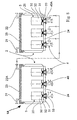
- the reactor 1A comprises two vessels 2, which are similar to the vessel 2 shown in Figs. 1, 2 and 3.
- the gas outlet or exhaust 22A of a first vessel 2 is connected to the gas inlets 40A of the filter candles 3 of the second vessel 2.
- the gas removed out of the first vessel 2 is delivered to the second vessel 2 and reused for dispersing the solid phase and as the case may be for reacting within the synthesis.
- Fig. 9 shows a cross-sectional view of a filter candle 3D with a replacement body 34D as a fifth embodiment of a filter cartridge.
- the filter candle 3D is basically set up according to the filter candle described in Fig. 1. It comprises an upper chamber 30D and a lower chamber 31D separated by an intermediate bottom 32D.
- the intermediate bottom 32D has a centrally arranged opening 321D connecting the upper chamber 30D and the lower chamber 31D.
- a spring-loaded back-pressure poppet valve 33D with a disk shaped valve head 331D is arranged at the bottom of the filter candle 3D.
- the cylindrical replacement body 34D is centrally arranged in the upper chamber 30D. It is impermeable for a liquid phase and comprises an upper part 34D and a lower part 35D.
- the lower part 35D is hollow and comprises a plurality of wall openings 36D.
- the liquid phase filtered through filtering walls of the filter candle 3D runs between the filtering walls and the replacement body 34D through the wall openings 36D into the inner of the lower part 35D. If the spring-loaded back-pressure poppet valve 33D is open the liquid phase runs into the lower chamber 31D of the filter candle 3D and in the filtrate outlet 4.
- the replacement body 34D reduces the inner volume of the filter candle 3D accessible for a liquid phase filtered through filtering walls of the filter candle 3D. Since the inner volume of a filter candle without a replacement body 34D, as e.g. shown in Fig. 1, is not mixed, the overall unmixed volume of a reactor with filter candles 3D is significantly reduced.
Landscapes
- Chemical & Material Sciences (AREA)
- Organic Chemistry (AREA)
- Chemical Kinetics & Catalysis (AREA)
- General Health & Medical Sciences (AREA)
- Medicinal Chemistry (AREA)
- Life Sciences & Earth Sciences (AREA)
- Biochemistry (AREA)
- Biophysics (AREA)
- Analytical Chemistry (AREA)
- Genetics & Genomics (AREA)
- Health & Medical Sciences (AREA)
- Molecular Biology (AREA)
- Proteomics, Peptides & Aminoacids (AREA)
- Organic Low-Molecular-Weight Compounds And Preparation Thereof (AREA)
- Physical Or Chemical Processes And Apparatus (AREA)
- Devices And Processes Conducted In The Presence Of Fluids And Solid Particles (AREA)
- Mixers With Rotating Receptacles And Mixers With Vibration Mechanisms (AREA)
- Catalysts (AREA)
Abstract
Description
- The present invention relates to a reactor for solid phase synthesis.
- Such reactors comprising a vessel with a filter are used for example for solid phase syntheses of peptides or other organic compounds. Solid phase syntheses are often conducted in reactors comprising filter elements, in particular filtering bottoms. For suspending the solid phase in a solution of reactants, these apparatuses can comprise an agitator. Usually big scale apparatuses are provided with such agitators. The common feature of all these apparatuses is a planar filter bottom for filtering the liquid phase after the synthesis and/or after a washing procedure. The apparatuses without agitators, which are typically used for laboratory applications, often mix the reactants and the solid phase by supplying a gas through the filter bottom.
- A solid phase synthesis in such apparatuses proceeds for example as follows: After positioning the solid phase in the apparatus the solution of the reactants is added. The chemical reaction of the solution and the solid phase is now going on. During this reaction it is important that the solution is mixed well with the solid phase. After a certain time the liquid phase is removed out of the apparatus by filtering it through the filter bottom. The remaining solid phase is washed by the following washing procedure which is usually applied several times one after another: A washing medium is added to the remaining solid phase in the apparatus. The washing medium is acting on the solid phase while again it is important that the solid phase and the liquid phase (washing medium) are well mixed. After a certain time the washing medium is removed from the apparatus by filtering it through the filter bottom. The solid phase with a product, for example an intermediate product, built on itself remains in the apparatus ready for the next cycle-step of the synthesis to take place by adding a next solution of reactants and repeating the whole procedure. The procedure is repeated with solutions of same or different reactants until the desired product is built on the solid phase. At the end the product has only to be cleaved off of the solid phase.
- During the filtration, which is applied in several steps of the above described procedure with an above described apparatus, a filter cake is built on the filter. The filtration time is dependent of the thickness of the filter cake and of the material of the solid phase. Especially in large scale procedures, e.g. procedures in a kg-scale up to a 100 kg-scale, with a substantial number of synthesis cycles, e.g. 15 which causes e.g. 135 filtering steps, the overall filtration time is limiting the efficiency of the whole synthesis. The thickness of the filter cake is dependent of the scale of the synthesis and the filtration time. It is growing with the scale in respect of the synthesis in a given apparatus and with advancing filtering time.
- The material of the solid phase is another key factor for the filtration time. Materials causing a big filter resistance in the filter cake, e.g. fine-grained and/or compressible materials, have a negative impact on the synthesis procedure in respect of the filtration time. Therefore solid phase synthesis cannot be carried out in an economic manner using any solid phase. The filtering properties of the solid phase have also to be taken in account. A compressible solid phase or any solid phase causing a big filter resistance can cause uneconomic overall process times.
- In apparatuses with an agitator the mechanical strain caused by agitating forces can partly destroy the solid phase. This destruction of the solid phase produces small fractions which have an impact on the filter resistance. The filter resistance is increasing and the filtration time is growing with increasing destruction of the solid phase. In some situations the filtration can be totally stopped since the solid phase is blocking the filter. Therefore, again solid phase synthesis cannot be carried out in an economic manner using any solid phase. The mechanical resistance to the forces produced by the agitator of the solid phase have also to be taken in account.
- To solve the above described problems of solid phase syntheses in large scales, various continuous-flow apparatuses and procedures using centrifuges or columns have been developed. However, they are in general technically and/or procedurally complex and expensive.
- Document
WO 94/00217 - In view of the disadvantages of the hitherto known, above described reactors for solid phase synthesis, the object of the invention is to provide a simple and inexpensive apparatus for economic large scale solid phase synthesis.
- This object is achieved by a reactor for solid phase synthesis according to the invention as it is defined in the independent claim 1. Preferred embodiments can be gathered from the dependent claims.
- The gas, which can pass from the bottom to the top of the vessel, causes turbulences in a solution of reactants filled in the vessel and mixes the solution with the solid phase. For this reason, no agitator is necessary for a sufficient mixture in the vessel in order that an efficient synthesis is possible. In the reactor according to the invention the solid phase does not have to meet any requirements of filtering properties or mechanical resistance. If filters are used building filter cakes horizontally beside them, the gas loosens the filter cake of the filter and remixes the solid phase of the filter cake with the solution. By using such filters the filtering properties and the filtering time of the reactor can be hold constantly good. Suitable gases to be delivered to the vessel can be gases which react or which do not react with the solid phase and/or the other reactants, for example N2, O2, O3, air, SO2, chlorine or hydrogen chloride.
- The filter of the reactor according the invention can comprise a filter cartridge, preferably a filter candle. Such filters are preferable embodiments of filters building filter cakes horizontally beside them as described above.
- The filter cartridge of the reactor comprises an intermediate bottom separating the filter cartridge in a lower chamber and an upper chamber. The lower chamber is connected to the filtrate outlet. The filter cartridge further comprises a one-way valve connecting the upper chamber with the lower chamber such that the intermediate bottom is pervious in direction from the upper chamber to the lower chamber but not in direction from the lower chamber to the upper chamber. With this kind of filters the gas can be delivered into the vessel via the lower chamber of the filter cartridge. Since it is not able to pass the intermediate bottom of the filter cartridge, it leaves the lower chamber through its sidewalls and enters the vessel automatically near to the bottom of the vessel and beside the filter.
- The filtrate outlet can comprise a gas inlet for delivering the gas into the vessel through the lower chamber of the filter cartridge. This preferred embodiment of delivering the gas into the vessel allows to use the filtrate outlet also as a gas inlet. The function of the filtrate outlet can change alternating from outlet to inlet.
- The vessel of a reactor according to the invention comprises preferably a plurality of filters. A plurality of smaller filters can have a bigger filtering surface than one bigger filter, so that the ratio between filtering surface and vessel bottom surface can be optimized. Furthermore, the thickness of the filter cake on a filter can be limited by using a plurality of filters to the half of the distance between adjacent filter.
- The vessel of the reactor according to the invention advantageously comprises a double casing for temperature regulation. The double casing can comprise means for keeping the temperature in the vessel at a constant temperature optimized for the synthesis.
- In a preferred embodiment of the invention the filter or filters comprise a slotted screen filter medium. Such a filter medium is a preferred strong medium successfully used in solid phase syntheses like for example in peptide synthesis.
- The vessel can comprise a filtrate inlet connected to the filtrate outlet, such that the filtrate can return from the filtrate outlet via the filtrate inlet into the vessel. With such a vessel the solution can continuously circulate in the reactor. The solution can be recycled during the synthesis procedure. This is economically and ecologically advantageous for the overall procedure.
- In a preferred embodiment of the invention the vessel comprises an exhaust connected to the means for delivering the gas such that the exhausted gas can return back into the vessel. In this way the gas can be almost completely recycled, which is economically and ecologically advantageous for the overall procedure.
- The reactor can comprise a cascade of vessels each comprising an exhaust, which vessels are connected together in such a way that the exhaust of one vessel is connected to the means for delivering the gas of the following vessel. The gas can be recycled in a plurality of vessels and the efficiency of the gas increases, which is economically and ecologically advantageous for the overall procedure.
- The reactor for solid phase synthesis according to the invention is described in more detail hereinbelow by way of exemplary embodiments and with reference to the attached drawings, in which:
- Fig. 1 -
- shows a cross-sectional view of a first embodiment of a reactor according to the invention with a first embodiment of a vessel and a first embodiment of filter cartridges;
- Fig. 2 -
- shows a schematic sectional view of the reactor according to line II-II in Fig. 1;
- Fig. 3 -
- shows a schematic perspective view of the reactor of Fig. 1;
- Fig. 4 -
- shows a schematic sectional view of a second embodiment of a vessel with filter cartridges according to the first embodiment;
- Fig. 5 -
- shows a schematic sectional view of the vessel of Fig. 4 with a second embodiment of filter cartridges;
- Fig. 6 -
- shows a schematic sectional view of the vessel of Fig. 4 with a third embodiment of filter cartridges;
- Fig. 7 -
- shows a schematic sectional view of the vessel of Fig. 4 with a fourth embodiment of filter cartridges;
- Fig. 8 -
- shows a cross-sectional view of a second embodiment of a reactor according to the invention comprising two vessels; and
- Fig. 9 -
- shows a cross-sectional view of a fifth embodiment of a filter cartridge with a replacement body.
- Fig. 1 shows a cross-sectional view of a first embodiment of a reactor 1 according to the invention with a first embodiment of a
vessel 2 and a first embodiment of filters in form offilter cartridges 3. Thevessel 2 comprises aremovable cover 23, atubular inlet 21 and atubular outlet 22, which are both arranged at thecover 23 and through which a medium can be delivered into respectively removed out of thevessel 2. At its lateral sides thevessel 2 comprises adouble casing 20. On the bottom 24 of the vessel 2 a plurality of filters is arranged, each filter comprising a vertically arrangedfilter candle 3 as a filter cartridge. In the present case, thefilter candles 3 are fixed by a bayonet joint to the bottom 24, O-rings 25 being provided in the joint region for sealing. Eachfilter candle 3 comprises a cylindrical hollow body with filtering walls. The interior of thefilter candle 3 is separated in anupper chamber 30 and alower chamber 31 by anintermediate bottom 32. The intermediate bottom 32 has a centrally arrangedopening 321 connecting theupper chamber 30 and thelower chamber 31. Below the opening 321 a spring-loaded back-pressure poppet valve 33 with a disk shapedvalve head 331 is arranged at the bottom of thefilter candle 3 as a one-way valve, such that thevalve head 331 obturates theopening 321 in a normal state. Alternatively the spring-loaded back-pressure poppet valve 33 can be arranged on means for valve attachment, which are attached themselves at theintermediate bottom 32. During removal of the filtrate out of thefilter candle 3 thevalve head 331 is moved away from theopening 321, such that the intermediate bottom 32 is pervious in direction from theupper chamber 30 to thelower chamber 31. This situation is shown in Fig. 1. At the bottom of each filter candle 3 atubular filtrate outlet 4 is connected to thelower chamber 31. Thefiltrate outlet 4 has a vertically arrangedmain tube 41 and a horizontally arrangedgas inlet 40. - For a synthesis a dry solid phase or a solid phase suspended in a liquid can be delivered into the
vessel 2 through theinlet 21. The solid phase is followed by a solution of reactants also delivered through theinlet 21 or through thegas inlet 40 and/or themain tube 41 into thevessel 2, such that the chemical reaction between the solution and the solid phase can start. The temperature in thevessel 2 can be optimized for the synthesis through a medium for heat exchange, which is conducted in thedouble casing 20 of thevessel 2. After a certain time the liquid phase (solution) can be removed out of thevessel 2. To effect this, the pressure conditions in the reactor 1 are changed, for example by closing theoutlet 22 and delivering N2 into thevessel 2 via theinlet 21 to raise the pressure, such that thevalve head 331 is moved away from theopening 321 and the liquid phase is conducted through the walls of thefilter candles 3, the hollow interior of thefilter candles 3 and theopenings 321 into thefiltrate outlets 4. The walls of thefilter candles 3 are made of a filter medium, preferably a streamline filter medium, particularly a slotted screen filter medium. Like this the particles of the solid phase get caught by the walls and remain in thevessel 2. After the solution is removed out of the vessel 2 a washing medium can be delivered to thevessel 2 through theinlet 21 or through thegas inlet 40 and/or themain tube 41. After a certain time the liquid phase (washing medium) is removed out of thevessel 2 again through thefilter candles 3. This washing process can be repeated several times. In a next step again a solution can be delivered into thevessel 2 through theinlet 21 or through thegas inlet 40 and/or themain tube 41 and the next cycle of the synthesis can start. - During the filtering steps of the synthesis a filter cake consisting of the solid phase of the synthesis is built on the walls of the
filter candles 3. A gas is blown through thegas inlet 40 and themain tube 41 of thefiltrate outlet 4 into the lower chamber of thefilter candle 3 while thevalve head 331 of the spring-loaded back-pressure poppet valve 33 obturates theopening 321 in theintermediate bottom 32. The gas streams out of all side-walls of thelower chamber 31 into thevessel 2, bubbles up thevessel 2, suspends the solid phase from the walls of thefilter candles 3 and disperses the solid phase gathered at thefilter candles 3 or settled at the bottom 24 of thevessel 2 by gravitation. Like this the solid phase can be mixed with the liquid phase in thevessel 2. The blowing of the gas into thevessel 2 advantageously happens intermittently to save gas. The gas itself can participate as a reactant in the synthesis, for example O2, O3, air, SO2, chlorine or hydrogen chloride, or be inert, for example N2. The remaining gas can leave thevessel 2 via theoutlet 22, which acts in this case as an exhaust. - The following applies to the rest of this description. If, in order to clarify the drawings, a figure contains reference signs which are not explained in the directly associated part of the description, then it is referred to previous description parts.
- Fig. 2 shows a schematic sectional view of the reactor 1 of Fig. 1. The
vessel 2 has a circular outline and comprises sevenfilter candles 3 regularly arranged at the bottom 24 of thevessel 2. Eachfilter candle 3 is connected to afiltrate outlet 4. With a regular arrangement of filtering elements at the bottom 24 of thevessel 2 clearance volume can be prevented where the solid phase gathered at thefilter candles 3 or settled at the bottom of thevessel 2 by gravitation cannot be sufficiently reached by the gas flow. - Fig. 3 shows a schematic perspective view of the reactor of Fig. 1. The
vessel 2 and thefilter candles 3 are of a cylindrical shape with circular outline and with vertically arranged axes. Eachfilter candle 3 comprises a cylindricalupper chamber 30 arranged on top of a cylindricallower chamber 31, separated by aintermediate bottom 32. The intermediate bottom 32 comprises a centrally arrangedopening 321 under which a spring-loaded back-pressure poppet valve 33 is arranged. - Fig. 4 shows a schematic sectional view of a second embodiment of a
vessel 2A with thefilter cartridges 3 according to the embodiment of Fig. 1. Thevessel 2A has a square outline and comprises ninecylindrical filter candles 3 as described above. - Figs. 5, 6 and 7 show schematic sectional views of the
vessel 2A of the embodiment of Fig. 4 but each with other embodiments offilter cartridges filter cartridges filter candles 3 described above. They all are hollow and comprise anupper chamber 30 and alower chamber 31 separated by anintermediate bottom 32. Each intermediate bottom 32 comprises anopening 321 under which a one-way valve 33 is arranged and which is connected to afiltrate outlet 4. These basic setups are not displayed in Figs. 5, 6 and 7. - Fig. 5 shows filter
candles 3A with square outlines. The square outlines of thefilter candles 3A allow constant distances between thefilter candles 3A and between thefilter candles 3A and the walls of thevessel 2A. This allows a homogeneous synthesis especially invessels 2A with square outlines. - Fig. 6 shows
plate filter elements 3B as filter cartridges. Theplate filter elements 3B are arranged in parallel end-to-end from one wall of thevessel 2A to an opposite wall of thevessel 2A. - Fig. 7 shows alternatively to Fig. 6 indented plate filter elements 3C. Several indented plate filter elements 3C are arranged in parallel starting right-angled to a first wall of the
vessel 2A in direction of a second wall which is the opposite wall of the first wall. The indented plate filter elements 3C end before reaching the second wall. The adjacent indented plate filter elements 3C to the indented plate filter elements 3C starting at the first wall start at the second wall and end before reaching the first wall. - The filter medium used for the different embodiments of
filter cartridges - Fig. 8 shows a cross-sectional view of a further embodiment of a reactor according to the invention. The
reactor 1A comprises twovessels 2, which are similar to thevessel 2 shown in Figs. 1, 2 and 3. The gas outlet orexhaust 22A of afirst vessel 2 is connected to thegas inlets 40A of thefilter candles 3 of thesecond vessel 2. The gas removed out of thefirst vessel 2 is delivered to thesecond vessel 2 and reused for dispersing the solid phase and as the case may be for reacting within the synthesis. - Fig. 9 shows a cross-sectional view of a
filter candle 3D with areplacement body 34D as a fifth embodiment of a filter cartridge. Thefilter candle 3D is basically set up according to the filter candle described in Fig. 1. It comprises anupper chamber 30D and alower chamber 31D separated by anintermediate bottom 32D. Theintermediate bottom 32D has a centrally arrangedopening 321D connecting theupper chamber 30D and thelower chamber 31D. Below theopening 321D a spring-loaded back-pressure poppet valve 33D with a disk shapedvalve head 331D is arranged at the bottom of thefilter candle 3D. - The
cylindrical replacement body 34D is centrally arranged in theupper chamber 30D. It is impermeable for a liquid phase and comprises anupper part 34D and alower part 35D. Thelower part 35D is hollow and comprises a plurality ofwall openings 36D. - During the use of the
filter candle 3D, the liquid phase filtered through filtering walls of thefilter candle 3D runs between the filtering walls and thereplacement body 34D through thewall openings 36D into the inner of thelower part 35D. If the spring-loaded back-pressure poppet valve 33D is open the liquid phase runs into thelower chamber 31D of thefilter candle 3D and in thefiltrate outlet 4. - The
replacement body 34D reduces the inner volume of thefilter candle 3D accessible for a liquid phase filtered through filtering walls of thefilter candle 3D. Since the inner volume of a filter candle without areplacement body 34D, as e.g. shown in Fig. 1, is not mixed, the overall unmixed volume of a reactor withfilter candles 3D is significantly reduced. - Other alternative embodiments of the reactor according to the invention are realizable. Explicitly mentioned in this context are:
- The exhaust of the vessel can be connected to the gas inlets of the filter candles of the same vessel to recycle the gas.
- The filtrate outlet of the reactor is connected to the inlet in order that the reactor can be used as a continuous flow reactor. The liquid phase circulates in the reactor.
- The body of the filter cartridge can basically be of any shape, like e.g. a filter candle with an oval outline or a filter candle with ring shaped outlines.
- The reactor can comprise one filtrate outlet for a plurality of filters. For this purpose the filters can be connected together. For example the lower chambers can be connected in a way that the filtrate of a plurality of filters is gathered in one filtrate outlet.
- The filters can be attached to the vessel in other ways than to its bottom with the help of bayonet joints and O-rings, for example with a snap in lock at the bottom, the sidewalls or the cover of the vessel or for example screwed in the bottom.
- Instead of the slotted screen filter medium basic single-layer or multi-layer filter media can be used.
Claims (9)
- Reactor (1; 1A) for solid phase synthesis comprising a vessel (2), a fitter (3; 3A; 3B; 3C; 3D) arranged in the vessel (2) and a filtrate outlet (4) for evacuating the filtrate out of the filter, the filter being connected to the filtrate outlet (4), wherein comprises means (3; 4; 3A; 3B; 3C; 3D) for delivering a gas into the vessel (2) in a region of the vessel (2) near to the bottom (24) of the vessel (2) and beside the filter (3; 3A; 3B; 3C; 3D) and characterized in that the filter comprises a filter cartridge (3; 3A; 3B; 3C; 3D) which comprises
an intermediate bottom (32; 32D) separating the filter cartridge (3; 3A, 3B; 3C; 3D) in a lower chamber (31; 31D) connected to the filtrate outlet (4) and an upper chamber (30; 30D); and
a one-way valve (33; 33D) connecting the upper chamber (30; 30D) with the lower chamber (31; 31D) such that the intermediate bottom (32; 32D) is previous in direction from the upper chamber (30; 30D) to the lower chamber (31; 31D) but not in direction from the lower chamber (31; 31D) to the upper chamber (30; 30D). - Reactor (1; 1A) according to claim 1, characterized in that the filter cartridge (3; 3A; 3B; 3C; 3D) is a filter candle.
- Reactor (1; 1A) according to claim 1 or 2, characterized in that the filtrate outlet (4) comprises a gas inlet (40; 40A) for delivering the gas into the vessel (2) through the lower chamber (31; 31D) of the filter cartridge (3; 3A; 3B; 3C; 3D).
- Reactor (1; 1A) according to one of claims 1 to 3, characterized in that the vessel (2) comprises a plurality of filters (3; 3A; 3B; 3C, 3D).
- Reactor (1; 1A) according to one of claims 1 to 4, characterized in that the vessel (2) comprises a double casing (20) for temperature regulation.
- Reactor (1; 1A) according to one of claims 1 to 5, characterized in that the filter (3; 3A; 3B; 3C; 3D) or filters comprise a slotted screen filter medium.
- Reactor (1; 1A) according to one of claims 1 to 6, characterised in that the vessel (2) comprises a filtrate inlet (21) connected to the filtrate outlet (4) such that the fultrate can return from the filtrate outlet (4) via the filtrate inlet (21) into the vessel (2).
- Reactor (1; 1A) according to one of claims 1 to 7, characterized in that the vessel (2) comprises an exhaust (22; 22A) connected to the means (3; 4; 3A; 3B; 3C; 3D) for the gas such that the exhausted gas can return back into the vessel (2).
- Reactor (1; 1A) according 10 one of claims 1 to 8, characterized in that it comprises a cascade of vessels (2) each comprising an exhaust (22; 22A), which vessels (2) are connected together in such a way that the exhaust (22; 22A) of one vessel (2) is connected to the means (3; 4; 3A; 3B; 3C; 3D) for delivering the gas of the following vessel (2).
Priority Applications (1)
| Application Number | Priority Date | Filing Date | Title |
|---|---|---|---|
| EP04797941A EP1689508B1 (en) | 2003-11-26 | 2004-11-17 | Reactor for solid phase synthesis |
Applications Claiming Priority (3)
| Application Number | Priority Date | Filing Date | Title |
|---|---|---|---|
| EP03104393 | 2003-11-26 | ||
| PCT/EP2004/013007 WO2005051515A1 (en) | 2003-11-26 | 2004-11-17 | Reactor for solid phase synthesis |
| EP04797941A EP1689508B1 (en) | 2003-11-26 | 2004-11-17 | Reactor for solid phase synthesis |
Publications (2)
| Publication Number | Publication Date |
|---|---|
| EP1689508A1 EP1689508A1 (en) | 2006-08-16 |
| EP1689508B1 true EP1689508B1 (en) | 2007-12-12 |
Family
ID=34626415
Family Applications (1)
| Application Number | Title | Priority Date | Filing Date |
|---|---|---|---|
| EP04797941A Expired - Lifetime EP1689508B1 (en) | 2003-11-26 | 2004-11-17 | Reactor for solid phase synthesis |
Country Status (8)
| Country | Link |
|---|---|
| US (1) | US7563412B2 (en) |
| EP (1) | EP1689508B1 (en) |
| JP (1) | JP4393520B2 (en) |
| KR (1) | KR101154179B1 (en) |
| AT (1) | ATE380572T1 (en) |
| DE (1) | DE602004010713T2 (en) |
| ES (1) | ES2297511T3 (en) |
| WO (1) | WO2005051515A1 (en) |
Families Citing this family (3)
| Publication number | Priority date | Publication date | Assignee | Title |
|---|---|---|---|---|
| DE102005036055A1 (en) * | 2005-08-01 | 2007-02-08 | Degussa Ag | Reactor for the production of organic peroxides via the intermediate of a solid hydrogen peroxide |
| US20100119734A1 (en) * | 2008-11-07 | 2010-05-13 | Applied Materials, Inc. | Laminar flow in a precursor source canister |
| CN110755909A (en) * | 2019-11-13 | 2020-02-07 | 攀枝花钢企欣宇化工有限公司 | Output structure for brine production system |
Family Cites Families (12)
| Publication number | Priority date | Publication date | Assignee | Title |
|---|---|---|---|---|
| US3184062A (en) * | 1962-02-27 | 1965-05-18 | Wix Corp | Filter unit |
| US3369666A (en) * | 1965-09-22 | 1968-02-20 | Champion Lab Inc | Filter unit with anti-drain back valve means |
| GB1272756A (en) * | 1968-07-13 | 1972-05-03 | Gen Motors Ltd | Liquid filter units |
| US3666097A (en) * | 1970-06-08 | 1972-05-30 | Ecodyne Corp | Method and apparatus for cleaning a filter cartridge |
| US3695437A (en) * | 1971-01-11 | 1972-10-03 | Hastings Mfg Co | Oil filter with improved anti-drainback valve |
| RU2033843C1 (en) * | 1992-06-19 | 1995-04-30 | Анатолий Васильевич Соколов | Filter for suspension separation |
| US5468397A (en) * | 1993-03-16 | 1995-11-21 | Memtec America Corporation | Gas backwash of pleated filters |
| GB2281224B (en) * | 1993-08-24 | 1998-02-11 | Norske Stats Oljeselskap | Solid/liquid slurry treatment apparatus and catalytic multi-phase reactor |
| GB9909630D0 (en) * | 1999-04-28 | 1999-06-23 | Zeneca Ltd | Reactor |
| US6320025B1 (en) * | 1999-07-29 | 2001-11-20 | Dario Slavazza | Solid phase peptide synthesis reaction vessel |
| US6974539B1 (en) * | 2001-10-01 | 2005-12-13 | Wix Filtration Corp. | Combination filter element support and anti-prefill valve |
| SE519369C2 (en) * | 2002-03-21 | 2003-02-18 | Malmkvist Ab O | Ways to clean a filter rod for filtering a particle-containing liquid and filter device |
-
2004
- 2004-11-17 WO PCT/EP2004/013007 patent/WO2005051515A1/en not_active Ceased
- 2004-11-17 DE DE602004010713T patent/DE602004010713T2/en not_active Expired - Lifetime
- 2004-11-17 EP EP04797941A patent/EP1689508B1/en not_active Expired - Lifetime
- 2004-11-17 ES ES04797941T patent/ES2297511T3/en not_active Expired - Lifetime
- 2004-11-17 US US10/580,993 patent/US7563412B2/en not_active Expired - Fee Related
- 2004-11-17 AT AT04797941T patent/ATE380572T1/en not_active IP Right Cessation
- 2004-11-17 JP JP2006540298A patent/JP4393520B2/en not_active Expired - Fee Related
- 2004-11-17 KR KR1020067010249A patent/KR101154179B1/en not_active Expired - Fee Related
Also Published As
| Publication number | Publication date |
|---|---|
| WO2005051515A1 (en) | 2005-06-09 |
| EP1689508A1 (en) | 2006-08-16 |
| US7563412B2 (en) | 2009-07-21 |
| JP4393520B2 (en) | 2010-01-06 |
| KR20060120149A (en) | 2006-11-24 |
| JP2007512125A (en) | 2007-05-17 |
| US20070081922A1 (en) | 2007-04-12 |
| ATE380572T1 (en) | 2007-12-15 |
| KR101154179B1 (en) | 2012-06-14 |
| DE602004010713D1 (en) | 2008-01-24 |
| ES2297511T3 (en) | 2008-05-01 |
| DE602004010713T2 (en) | 2008-12-04 |
Similar Documents
| Publication | Publication Date | Title |
|---|---|---|
| US6238929B1 (en) | Systems and methods for the synthesis of organic compounds | |
| RU2006104329A (en) | METHOD FOR PRODUCING LIQUID AND GAS PRODUCTS FROM GAS REAGENTS | |
| RU94040360A (en) | Method to exercise continuous multiphase reaction of catalytic transformation | |
| EA004758B1 (en) | Process and device for carrying out reactions in a reactor with slot-shaped reaction spaces | |
| EP2043774A2 (en) | Internal loop reactor and oxo process using same | |
| CN101711965A (en) | System and method for continuous multiphase reaction and separation | |
| RU95121590A (en) | MULTI-STEP METHOD OF SUSPENSION REACTIVE STEAM AND DEVICE FOR ITS IMPLEMENTATION | |
| CN1791459B (en) | chemical reactor | |
| WO2019224376A1 (en) | Apulsedflow reactorandusethereof | |
| US7563412B2 (en) | Reactor for solid phase synthesis | |
| ZA200703662B (en) | Device for producing liquid hydrocarbons by Fisher-Tropsch synthesis in a three-phase bed reactor | |
| JP2004533315A (en) | Reactors for gas / liquid or gas / liquid / solid reactions | |
| CN113952896A (en) | Device and method for continuous preparation of triphosgene | |
| EP1594585B1 (en) | Olefin epoxidation process employing an in situ filtration draught tube reactor system | |
| US5387349A (en) | Liquid phase reaction process | |
| GB2475401A (en) | Agitated cell reactors | |
| CN216419327U (en) | Device for continuously preparing triphosgene | |
| CN107537409B (en) | Cascade oxidation reaction method, assembly and application thereof | |
| RU98109585A (en) | HYDROLYSIS REACTOR FOR REMOVING UREA, AMMONIA AND CARBON DIOXIDE FROM A LIQUID PHASE CONTAINING UREA IN AQUEOUS SOLUTION | |
| CN204469676U (en) | Oxidation reaction apparatus | |
| JP2006231160A (en) | Reaction vessel parallel connected type automatic synthesis apparatus | |
| JP4925276B2 (en) | Mixer-setra type Bunsen reactor | |
| SU1000094A1 (en) | Gas liquid reactor | |
| SU1286231A1 (en) | Mass exchange apparatus | |
| SU1000093A1 (en) | Reactor |
Legal Events
| Date | Code | Title | Description |
|---|---|---|---|
| PUAI | Public reference made under article 153(3) epc to a published international application that has entered the european phase |
Free format text: ORIGINAL CODE: 0009012 |
|
| 17P | Request for examination filed |
Effective date: 20060626 |
|
| AK | Designated contracting states |
Kind code of ref document: A1 Designated state(s): AT BE BG CH CY CZ DE DK EE ES FI FR GB GR HU IE IS IT LI LU MC NL PL PT RO SE SI SK TR |
|
| DAX | Request for extension of the european patent (deleted) | ||
| GRAP | Despatch of communication of intention to grant a patent |
Free format text: ORIGINAL CODE: EPIDOSNIGR1 |
|
| GRAS | Grant fee paid |
Free format text: ORIGINAL CODE: EPIDOSNIGR3 |
|
| GRAA | (expected) grant |
Free format text: ORIGINAL CODE: 0009210 |
|
| AK | Designated contracting states |
Kind code of ref document: B1 Designated state(s): AT BE BG CH CY CZ DE DK EE ES FI FR GB GR HU IE IS IT LI LU MC NL PL PT RO SE SI SK TR |
|
| REG | Reference to a national code |
Ref country code: GB Ref legal event code: FG4D |
|
| REG | Reference to a national code |
Ref country code: CH Ref legal event code: EP |
|
| REG | Reference to a national code |
Ref country code: IE Ref legal event code: FG4D |
|
| REF | Corresponds to: |
Ref document number: 602004010713 Country of ref document: DE Date of ref document: 20080124 Kind code of ref document: P |
|
| PG25 | Lapsed in a contracting state [announced via postgrant information from national office to epo] |
Ref country code: SE Free format text: LAPSE BECAUSE OF FAILURE TO SUBMIT A TRANSLATION OF THE DESCRIPTION OR TO PAY THE FEE WITHIN THE PRESCRIBED TIME-LIMIT Effective date: 20080312 |
|
| REG | Reference to a national code |
Ref country code: ES Ref legal event code: FG2A Ref document number: 2297511 Country of ref document: ES Kind code of ref document: T3 |
|
| PG25 | Lapsed in a contracting state [announced via postgrant information from national office to epo] |
Ref country code: FI Free format text: LAPSE BECAUSE OF FAILURE TO SUBMIT A TRANSLATION OF THE DESCRIPTION OR TO PAY THE FEE WITHIN THE PRESCRIBED TIME-LIMIT Effective date: 20071212 Ref country code: SI Free format text: LAPSE BECAUSE OF FAILURE TO SUBMIT A TRANSLATION OF THE DESCRIPTION OR TO PAY THE FEE WITHIN THE PRESCRIBED TIME-LIMIT Effective date: 20071212 Ref country code: NL Free format text: LAPSE BECAUSE OF FAILURE TO SUBMIT A TRANSLATION OF THE DESCRIPTION OR TO PAY THE FEE WITHIN THE PRESCRIBED TIME-LIMIT Effective date: 20071212 Ref country code: PL Free format text: LAPSE BECAUSE OF FAILURE TO SUBMIT A TRANSLATION OF THE DESCRIPTION OR TO PAY THE FEE WITHIN THE PRESCRIBED TIME-LIMIT Effective date: 20071212 |
|
| NLV1 | Nl: lapsed or annulled due to failure to fulfill the requirements of art. 29p and 29m of the patents act | ||
| PG25 | Lapsed in a contracting state [announced via postgrant information from national office to epo] |
Ref country code: AT Free format text: LAPSE BECAUSE OF FAILURE TO SUBMIT A TRANSLATION OF THE DESCRIPTION OR TO PAY THE FEE WITHIN THE PRESCRIBED TIME-LIMIT Effective date: 20071212 |
|
| PG25 | Lapsed in a contracting state [announced via postgrant information from national office to epo] |
Ref country code: IS Free format text: LAPSE BECAUSE OF FAILURE TO SUBMIT A TRANSLATION OF THE DESCRIPTION OR TO PAY THE FEE WITHIN THE PRESCRIBED TIME-LIMIT Effective date: 20080412 Ref country code: CZ Free format text: LAPSE BECAUSE OF FAILURE TO SUBMIT A TRANSLATION OF THE DESCRIPTION OR TO PAY THE FEE WITHIN THE PRESCRIBED TIME-LIMIT Effective date: 20071212 |
|
| ET | Fr: translation filed | ||
| PG25 | Lapsed in a contracting state [announced via postgrant information from national office to epo] |
Ref country code: SK Free format text: LAPSE BECAUSE OF FAILURE TO SUBMIT A TRANSLATION OF THE DESCRIPTION OR TO PAY THE FEE WITHIN THE PRESCRIBED TIME-LIMIT Effective date: 20071212 Ref country code: RO Free format text: LAPSE BECAUSE OF FAILURE TO SUBMIT A TRANSLATION OF THE DESCRIPTION OR TO PAY THE FEE WITHIN THE PRESCRIBED TIME-LIMIT Effective date: 20071212 Ref country code: BE Free format text: LAPSE BECAUSE OF FAILURE TO SUBMIT A TRANSLATION OF THE DESCRIPTION OR TO PAY THE FEE WITHIN THE PRESCRIBED TIME-LIMIT Effective date: 20071212 |
|
| PG25 | Lapsed in a contracting state [announced via postgrant information from national office to epo] |
Ref country code: PT Free format text: LAPSE BECAUSE OF FAILURE TO SUBMIT A TRANSLATION OF THE DESCRIPTION OR TO PAY THE FEE WITHIN THE PRESCRIBED TIME-LIMIT Effective date: 20080512 |
|
| PLBE | No opposition filed within time limit |
Free format text: ORIGINAL CODE: 0009261 |
|
| STAA | Information on the status of an ep patent application or granted ep patent |
Free format text: STATUS: NO OPPOSITION FILED WITHIN TIME LIMIT |
|
| PG25 | Lapsed in a contracting state [announced via postgrant information from national office to epo] |
Ref country code: DK Free format text: LAPSE BECAUSE OF FAILURE TO SUBMIT A TRANSLATION OF THE DESCRIPTION OR TO PAY THE FEE WITHIN THE PRESCRIBED TIME-LIMIT Effective date: 20071212 |
|
| 26N | No opposition filed |
Effective date: 20080915 |
|
| PG25 | Lapsed in a contracting state [announced via postgrant information from national office to epo] |
Ref country code: GR Free format text: LAPSE BECAUSE OF FAILURE TO SUBMIT A TRANSLATION OF THE DESCRIPTION OR TO PAY THE FEE WITHIN THE PRESCRIBED TIME-LIMIT Effective date: 20080313 |
|
| PG25 | Lapsed in a contracting state [announced via postgrant information from national office to epo] |
Ref country code: BG Free format text: LAPSE BECAUSE OF FAILURE TO SUBMIT A TRANSLATION OF THE DESCRIPTION OR TO PAY THE FEE WITHIN THE PRESCRIBED TIME-LIMIT Effective date: 20080312 Ref country code: EE Free format text: LAPSE BECAUSE OF FAILURE TO SUBMIT A TRANSLATION OF THE DESCRIPTION OR TO PAY THE FEE WITHIN THE PRESCRIBED TIME-LIMIT Effective date: 20071212 |
|
| PG25 | Lapsed in a contracting state [announced via postgrant information from national office to epo] |
Ref country code: MC Free format text: LAPSE BECAUSE OF NON-PAYMENT OF DUE FEES Effective date: 20081130 |
|
| PG25 | Lapsed in a contracting state [announced via postgrant information from national office to epo] |
Ref country code: CY Free format text: LAPSE BECAUSE OF FAILURE TO SUBMIT A TRANSLATION OF THE DESCRIPTION OR TO PAY THE FEE WITHIN THE PRESCRIBED TIME-LIMIT Effective date: 20071212 |
|
| PG25 | Lapsed in a contracting state [announced via postgrant information from national office to epo] |
Ref country code: IE Free format text: LAPSE BECAUSE OF NON-PAYMENT OF DUE FEES Effective date: 20081117 |
|
| PG25 | Lapsed in a contracting state [announced via postgrant information from national office to epo] |
Ref country code: HU Free format text: LAPSE BECAUSE OF FAILURE TO SUBMIT A TRANSLATION OF THE DESCRIPTION OR TO PAY THE FEE WITHIN THE PRESCRIBED TIME-LIMIT Effective date: 20080613 Ref country code: LU Free format text: LAPSE BECAUSE OF NON-PAYMENT OF DUE FEES Effective date: 20081117 |
|
| PG25 | Lapsed in a contracting state [announced via postgrant information from national office to epo] |
Ref country code: TR Free format text: LAPSE BECAUSE OF FAILURE TO SUBMIT A TRANSLATION OF THE DESCRIPTION OR TO PAY THE FEE WITHIN THE PRESCRIBED TIME-LIMIT Effective date: 20071212 |
|
| REG | Reference to a national code |
Ref country code: FR Ref legal event code: PLFP Year of fee payment: 12 |
|
| PGFP | Annual fee paid to national office [announced via postgrant information from national office to epo] |
Ref country code: CH Payment date: 20151026 Year of fee payment: 12 Ref country code: GB Payment date: 20151027 Year of fee payment: 12 Ref country code: DE Payment date: 20151130 Year of fee payment: 12 Ref country code: IT Payment date: 20151112 Year of fee payment: 12 |
|
| PGFP | Annual fee paid to national office [announced via postgrant information from national office to epo] |
Ref country code: ES Payment date: 20151111 Year of fee payment: 12 Ref country code: FR Payment date: 20151027 Year of fee payment: 12 |
|
| REG | Reference to a national code |
Ref country code: DE Ref legal event code: R119 Ref document number: 602004010713 Country of ref document: DE |
|
| REG | Reference to a national code |
Ref country code: CH Ref legal event code: PL |
|
| GBPC | Gb: european patent ceased through non-payment of renewal fee |
Effective date: 20161117 |
|
| PG25 | Lapsed in a contracting state [announced via postgrant information from national office to epo] |
Ref country code: CH Free format text: LAPSE BECAUSE OF NON-PAYMENT OF DUE FEES Effective date: 20161130 Ref country code: LI Free format text: LAPSE BECAUSE OF NON-PAYMENT OF DUE FEES Effective date: 20161130 |
|
| REG | Reference to a national code |
Ref country code: FR Ref legal event code: ST Effective date: 20170731 |
|
| PG25 | Lapsed in a contracting state [announced via postgrant information from national office to epo] |
Ref country code: FR Free format text: LAPSE BECAUSE OF NON-PAYMENT OF DUE FEES Effective date: 20161130 Ref country code: IT Free format text: LAPSE BECAUSE OF NON-PAYMENT OF DUE FEES Effective date: 20161117 |
|
| PG25 | Lapsed in a contracting state [announced via postgrant information from national office to epo] |
Ref country code: DE Free format text: LAPSE BECAUSE OF NON-PAYMENT OF DUE FEES Effective date: 20170601 Ref country code: GB Free format text: LAPSE BECAUSE OF NON-PAYMENT OF DUE FEES Effective date: 20161117 |
|
| PG25 | Lapsed in a contracting state [announced via postgrant information from national office to epo] |
Ref country code: ES Free format text: LAPSE BECAUSE OF NON-PAYMENT OF DUE FEES Effective date: 20161118 |
|
| REG | Reference to a national code |
Ref country code: ES Ref legal event code: FD2A Effective date: 20181121 |