EP1689055A1 - Laser system - Google Patents
Laser system Download PDFInfo
- Publication number
- EP1689055A1 EP1689055A1 EP04819329A EP04819329A EP1689055A1 EP 1689055 A1 EP1689055 A1 EP 1689055A1 EP 04819329 A EP04819329 A EP 04819329A EP 04819329 A EP04819329 A EP 04819329A EP 1689055 A1 EP1689055 A1 EP 1689055A1
- Authority
- EP
- European Patent Office
- Prior art keywords
- laser
- heat
- laser system
- section
- support member
- Prior art date
- Legal status (The legal status is an assumption and is not a legal conclusion. Google has not performed a legal analysis and makes no representation as to the accuracy of the status listed.)
- Withdrawn
Links
Images




Classifications
-
- H—ELECTRICITY
- H01—ELECTRIC ELEMENTS
- H01S—DEVICES USING THE PROCESS OF LIGHT AMPLIFICATION BY STIMULATED EMISSION OF RADIATION [LASER] TO AMPLIFY OR GENERATE LIGHT; DEVICES USING STIMULATED EMISSION OF ELECTROMAGNETIC RADIATION IN WAVE RANGES OTHER THAN OPTICAL
- H01S5/00—Semiconductor lasers
- H01S5/02—Structural details or components not essential to laser action
- H01S5/024—Arrangements for thermal management
-
- H—ELECTRICITY
- H01—ELECTRIC ELEMENTS
- H01S—DEVICES USING THE PROCESS OF LIGHT AMPLIFICATION BY STIMULATED EMISSION OF RADIATION [LASER] TO AMPLIFY OR GENERATE LIGHT; DEVICES USING STIMULATED EMISSION OF ELECTROMAGNETIC RADIATION IN WAVE RANGES OTHER THAN OPTICAL
- H01S5/00—Semiconductor lasers
-
- H—ELECTRICITY
- H01—ELECTRIC ELEMENTS
- H01S—DEVICES USING THE PROCESS OF LIGHT AMPLIFICATION BY STIMULATED EMISSION OF RADIATION [LASER] TO AMPLIFY OR GENERATE LIGHT; DEVICES USING STIMULATED EMISSION OF ELECTROMAGNETIC RADIATION IN WAVE RANGES OTHER THAN OPTICAL
- H01S3/00—Lasers, i.e. devices using stimulated emission of electromagnetic radiation in the infrared, visible or ultraviolet wave range
-
- H—ELECTRICITY
- H01—ELECTRIC ELEMENTS
- H01S—DEVICES USING THE PROCESS OF LIGHT AMPLIFICATION BY STIMULATED EMISSION OF RADIATION [LASER] TO AMPLIFY OR GENERATE LIGHT; DEVICES USING STIMULATED EMISSION OF ELECTROMAGNETIC RADIATION IN WAVE RANGES OTHER THAN OPTICAL
- H01S5/00—Semiconductor lasers
- H01S5/02—Structural details or components not essential to laser action
- H01S5/022—Mountings; Housings
- H01S5/023—Mount members, e.g. sub-mount members
- H01S5/02315—Support members, e.g. bases or carriers
-
- H—ELECTRICITY
- H01—ELECTRIC ELEMENTS
- H01S—DEVICES USING THE PROCESS OF LIGHT AMPLIFICATION BY STIMULATED EMISSION OF RADIATION [LASER] TO AMPLIFY OR GENERATE LIGHT; DEVICES USING STIMULATED EMISSION OF ELECTROMAGNETIC RADIATION IN WAVE RANGES OTHER THAN OPTICAL
- H01S5/00—Semiconductor lasers
- H01S5/02—Structural details or components not essential to laser action
- H01S5/022—Mountings; Housings
- H01S5/0233—Mounting configuration of laser chips
-
- H—ELECTRICITY
- H01—ELECTRIC ELEMENTS
- H01S—DEVICES USING THE PROCESS OF LIGHT AMPLIFICATION BY STIMULATED EMISSION OF RADIATION [LASER] TO AMPLIFY OR GENERATE LIGHT; DEVICES USING STIMULATED EMISSION OF ELECTROMAGNETIC RADIATION IN WAVE RANGES OTHER THAN OPTICAL
- H01S5/00—Semiconductor lasers
- H01S5/02—Structural details or components not essential to laser action
- H01S5/022—Mountings; Housings
- H01S5/0235—Method for mounting laser chips
-
- H—ELECTRICITY
- H01—ELECTRIC ELEMENTS
- H01S—DEVICES USING THE PROCESS OF LIGHT AMPLIFICATION BY STIMULATED EMISSION OF RADIATION [LASER] TO AMPLIFY OR GENERATE LIGHT; DEVICES USING STIMULATED EMISSION OF ELECTROMAGNETIC RADIATION IN WAVE RANGES OTHER THAN OPTICAL
- H01S3/00—Lasers, i.e. devices using stimulated emission of electromagnetic radiation in the infrared, visible or ultraviolet wave range
- H01S3/10—Controlling the intensity, frequency, phase, polarisation or direction of the emitted radiation, e.g. switching, gating, modulating or demodulating
- H01S3/105—Controlling the intensity, frequency, phase, polarisation or direction of the emitted radiation, e.g. switching, gating, modulating or demodulating by controlling the mutual position or the reflecting properties of the reflectors of the cavity, e.g. by controlling the cavity length
- H01S3/1055—Controlling the intensity, frequency, phase, polarisation or direction of the emitted radiation, e.g. switching, gating, modulating or demodulating by controlling the mutual position or the reflecting properties of the reflectors of the cavity, e.g. by controlling the cavity length one of the reflectors being constituted by a diffraction grating
-
- H—ELECTRICITY
- H01—ELECTRIC ELEMENTS
- H01S—DEVICES USING THE PROCESS OF LIGHT AMPLIFICATION BY STIMULATED EMISSION OF RADIATION [LASER] TO AMPLIFY OR GENERATE LIGHT; DEVICES USING STIMULATED EMISSION OF ELECTROMAGNETIC RADIATION IN WAVE RANGES OTHER THAN OPTICAL
- H01S5/00—Semiconductor lasers
- H01S5/02—Structural details or components not essential to laser action
- H01S5/022—Mountings; Housings
- H01S5/02208—Mountings; Housings characterised by the shape of the housings
-
- H—ELECTRICITY
- H01—ELECTRIC ELEMENTS
- H01S—DEVICES USING THE PROCESS OF LIGHT AMPLIFICATION BY STIMULATED EMISSION OF RADIATION [LASER] TO AMPLIFY OR GENERATE LIGHT; DEVICES USING STIMULATED EMISSION OF ELECTROMAGNETIC RADIATION IN WAVE RANGES OTHER THAN OPTICAL
- H01S5/00—Semiconductor lasers
- H01S5/02—Structural details or components not essential to laser action
- H01S5/022—Mountings; Housings
- H01S5/023—Mount members, e.g. sub-mount members
- H01S5/02325—Mechanically integrated components on mount members or optical micro-benches
-
- H—ELECTRICITY
- H01—ELECTRIC ELEMENTS
- H01S—DEVICES USING THE PROCESS OF LIGHT AMPLIFICATION BY STIMULATED EMISSION OF RADIATION [LASER] TO AMPLIFY OR GENERATE LIGHT; DEVICES USING STIMULATED EMISSION OF ELECTROMAGNETIC RADIATION IN WAVE RANGES OTHER THAN OPTICAL
- H01S5/00—Semiconductor lasers
- H01S5/02—Structural details or components not essential to laser action
- H01S5/024—Arrangements for thermal management
- H01S5/02407—Active cooling, e.g. the laser temperature is controlled by a thermo-electric cooler or water cooling
- H01S5/02415—Active cooling, e.g. the laser temperature is controlled by a thermo-electric cooler or water cooling by using a thermo-electric cooler [TEC], e.g. Peltier element
-
- H—ELECTRICITY
- H01—ELECTRIC ELEMENTS
- H01S—DEVICES USING THE PROCESS OF LIGHT AMPLIFICATION BY STIMULATED EMISSION OF RADIATION [LASER] TO AMPLIFY OR GENERATE LIGHT; DEVICES USING STIMULATED EMISSION OF ELECTROMAGNETIC RADIATION IN WAVE RANGES OTHER THAN OPTICAL
- H01S5/00—Semiconductor lasers
- H01S5/02—Structural details or components not essential to laser action
- H01S5/024—Arrangements for thermal management
- H01S5/02438—Characterized by cooling of elements other than the laser chip, e.g. an optical element being part of an external cavity or a collimating lens
-
- H—ELECTRICITY
- H01—ELECTRIC ELEMENTS
- H01S—DEVICES USING THE PROCESS OF LIGHT AMPLIFICATION BY STIMULATED EMISSION OF RADIATION [LASER] TO AMPLIFY OR GENERATE LIGHT; DEVICES USING STIMULATED EMISSION OF ELECTROMAGNETIC RADIATION IN WAVE RANGES OTHER THAN OPTICAL
- H01S5/00—Semiconductor lasers
- H01S5/10—Construction or shape of the optical resonator, e.g. extended or external cavity, coupled cavities, bent-guide, varying width, thickness or composition of the active region
- H01S5/14—External cavity lasers
- H01S5/141—External cavity lasers using a wavelength selective device, e.g. a grating or etalon
Definitions
- the present invention relates to a laser system that contains an external cavity type semiconductor laser, more specifically, to a laser system whose temperature can be accurately controlled.
- semiconductor lasers feature small size and low power consumption, they have been used in many information devices. These semiconductor lasers include an external cavity type semiconductor laser that stabilizes the wavelength of oscillation light with external incident light having a predetermined wavelength.
- a typical Littrow type semiconductor laser will be described.
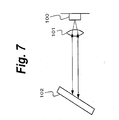
- Multiple longitudinal laser light emitted from a semiconductor laser device such as a laser diode 100 is collimated by a lens 101 and entered into a grating 102.
- the grating 102 outputs light having a predetermined wavelength as primary diffraction light of the incident light according to the arrangement angle.
- the primary diffraction light is reversely injected into the laser diode 100 through the lens 101.
- the laser diode 100 oscillates with the injected primary diffraction light and emits single mode light.
- the wavelength of the emitted light is the same as the wavelength of the light returned from the grating 102.
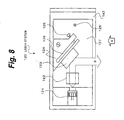
- Fig. 8 is a plan view showing a laser system 120.
- Fig. 9 is a front view showing the laser system 120 seen from the direction denoted by arrow A shown in Fig. 8.
- the structure of the laser system 120 is the same as the structure of the laser system described in L. Ricci, et. al., "A compact grating - stabilized diode laser system for atomic pliysics," Optics Communications, 117 1995, pp 541-549.
- the laser system 120 shown in Fig. 8 and Fig. 9 is composed of a laser section 130 that has a laser diode 121, a lens 122, a grating 123, a first support member 124, a first screw 125, a first groove 126, a second support member 127, a second screw 128, and a second groove 129; and a temperature control section 143 that has a Peltier device 141 and a heat sink 142.
- the temperature control section 143 is disposed below the laser section 130.
- the temperature control section 143 controls the temperatures of individual components such as the laser diode 121 and the lens 122 of the laser section 130.
- the temperature control section 143 keeps the temperature of the laser diode 121 constant, allowing an output of the light source to be stable.
- the wavelength of the oscillation light of the laser diode 121 is adjusted.
- the grating 123 is held by the first support member 124.
- the first support member 124 has the first groove 126.
- the space of the first groove 126 is widened or narrowed.
- the horizontal arrangement angle of the grating 123 slightly varies.
- the similar mechanism is disposed to adjust the vertical angle of the grating 123.
- the first support member 124 that supports the grating 123 is held by the second support member 127.
- the second support member 127 has the second groove 129.
- the space of the second groove 129 is partly widened or narrowed.
- the vertical arrangement angle of the first support member 124 and the grating 123 slightly varies.
- the temperature control section 143 is composed of the Peltier device 141 and the heat sink 142 that also has a function as a base.
- the Peltier device 141 When current flows in one direction of the Peltier device 141, one (first) surface thereof heats up, whereas the other (second) surface thereof cools down.
- the current flow direction is reversed, the first surface of the Peltier device 141 cools down, whereas the second surface thereof heats up.
- the Peltier device 141 When the Peltier device 141 is used, even if one surface thereof is cooled down at -10 °C against the ambient temperature, the other surface is not heated up at +10 °C against the ambient temperature. This is because heat generated in the Peltier device 141 is added to the temperature of the other surface.
- the laser section 130 when the laser section 130 is cooled down, a problem will occur.
- the temperature of the lower surface of the Peltier device 141 will become around plus several ten degree centigrade against the ambient temperature.
- the temperature of the heat sink 142 will become around +10 °C against the ambient temperature.
- heated air heats up the laser section 130.
- the laser section 130 is hardly cooled down.
- the holography memory writer is expected to be a next generation storage.
- the holography memory writer is considered to be used for a personal computer. In this case, since the internal temperature of the personal computer is high, when the external cavity type semiconductor laser is used, it will be cooled down.
- the external cavity type semiconductor laser is one component of the holography memory writer, the laser system needs to be small. Thus, it is not practical to cool down the external cavity type semiconductor laser with a large heat sink.
- an internal CPU is contacted with a heat sink so that heat generated in the CPU is transmitted to the heat sink.
- the heated heat sink is cooled down by an air blow of a fan that is rotated at high speed.
- the laser system may be cooled down by such a high-speed fan like the CPU.
- the holography needs highly accurate radiation with two beams of laser light. Thus, it is necessary to suppress the vibration of the external cavity type semiconductor laser as much as possible. Thus, it is not suitable to use a high-speed fan that largely vibrates the external cavity type semiconductor laser.
- an object of the present invention is to provide a laser system that is totally miniaturized.
- Another object of the present invention is to provide a laser system that suppresses the vibration of a laser section and effectively cools down it.
- the present invention is a laser system, comprising a base plate, a heat sink that is connected to the base plate and that is nearly perpendicular thereto, a heat generation device or a heat absorption device that is connected to the heat sink and that is nearly perpendicular to the base plate, and a laser section that is connected to the heat generation device or the heat absorption device and that is nearly perpendicular to the base plate, one surface of the heat generation device or the heat absorption device being connected to the laser section, the other surface of the heat generation device or the heat absorption device being connected to the heat sink, wherein the laser section has a semiconductor laser device, a lens, a grating, and a support member, the semiconductor laser device, the lens, and the grating composing an external cavity type semiconductor laser, the support member supporting the external cavity type semiconductor laser, wherein the laser section is connected to the heat generation device or the heat absorption device connected to the heat sink by the support member, and wherein the external cavity type semiconductor laser is covered by the support member and a lid that has heat
- the present invention is a laser system, comprising a heat sink that is directly connected to a surface plate and that is nearly perpendicular to the surface plate, a heat generation device or a heat absorption device that is connected to the heat sink and that is nearly perpendicular to the surface plate, and a laser section that is connected to the heat generation device or the heat absorption device and that is nearly perpendicular to the surface plate, one surface of the heat generation device or the heat absorption device being connected to the laser section, the other surface of the heat generation device or the heat absorption device being connected to the heat sink, wherein the laser section has a semiconductor laser device, a lens, a grating, and a support member, the semiconductor laser device, the lens, and the grating composing an external cavity type semiconductor laser, the support member supporting the external cavity type semiconductor laser, wherein the laser section is connected to the heat generation device or the heat absorption device connected to the heat sink by the support member, and wherein the external cavity type semiconductor laser is covered by the support member and a lid that has
- the laser system 1 is composed of a laser section 8 that has a laser diode 2, a lens 3, a grating 4, a first support member 5, a second support member 6, and a lid 7; and a temperature control section 12 that has a Peltier device 9, a heat sink 10, and a base plate 11.
- the laser diode 2, the lens 3, the grating 4, and so forth are covered by the lid 7 of the laser section 8 and the second support member 6.
- the lid 7 and the second support member 6 block air from entering into and exiting from the laser section 8 so that the temperatures of the laser diode 2, the lens 3, the grating 4, and so forth are kept constant.
- the structures of the other components of the laser section 8 are basically the same as those of the laser section 130 shown in Fig. 8 and Fig. 9.
- the optical components such as the laser diode 121, the lens 122, the grating 123, and so forth are horizontally arranged on the arrangement surface of the laser system 120.
- the optical components are arranged perpendicular to the arrangement surface of the laser system 1.
- a temperature sensor (not shown) is disposed in the vicinity of the laser diode 2.
- the direction and amount of the current that flows in the Peltier device 9 are decided according to temperature data obtained by the temperature sensor so that the temperature of the laser section 8 is properly controlled.
- the position of the temperature sensor will be described with reference to Fig. 6.
- the temperature control section 12 is disposed on one side of the laser section 8. More specifically, the heat sink 10 is connected to the Peltier device 9.
- the Peltier device 9 is connected to the second support member 6 of the laser section 8. They need to be connected so that at least heat is transmitted therebetween for example by closely contacting them.
- a buffer member may be interposed between the heat sink 10 and the Peltier device 9 and between the Peltier device 9 and the second support member 6. Heat is transmitted between the grating 4 and the heat sink 10 through the first support member 5, the second support member 6, and the Peltier device 9.
- heat generated in the laser diode 2 and so forth is transmitted to the heat sink 10 through the second support member 6 and the Peltier device 9.
- the heat is further transmitted to the base plate 11. Since the heat sink 10 is disposed on one side of the laser section 8, it is not heated up with heated air that rises from the heat sink 10 unlike with the laser system 1 according to the related art. From this point, it can be said that heat of the heat sink 10 is hardly transmitted to the laser section 8.
- the laser diode 2 is used.
- another type of a semiconductor laser device may be used.
- the Peltier device 9 is used to control the temperature of the laser section 8.
- another type of a heat absorption device may be used.
- the temperature of the laser section 8 may be controlled only with a heat generation device. Likewise, these devices may be used in the following embodiments.
- the first embodiment there is a possibility of which heat is transmitted to the laser section 8 on a route denoted by arrow C.
- the heat sink 10 is heated up by 40 °C or higher through the Peltier device 9.
- the heat is transmitted to the base plate 11 on the route denoted by arrow C.
- the heat also heats up the lid 7 through air interposed between the base plate 11 and the lid 7.
- the laser section 8 is indirectly heated up by the heat of the lid 7.
- the laser section 8 is cooled down by the Peltier device 9 as described above, since the amount of heat transmitted on the route denoted by arrow C is much larger than the amount of heat cooled down by the Peltier device 9, the laser section 8 is heated up.
- the distance D needs to be around 5 mm. Since the temperature of the heat sink 10 does not decrease by at most 5 °C against the ambient temperature, cold air transmitted to the laser section 8 on the route denoted by arrow C is small.
- the lid 7 is made of a material that has a heat insulation effect, namely a material that has low thermal conductivity, such as heat resistance plastic. As the thickness of the lid 7 is decreased, the heat insulation effect is improved.
- a laser system 21 according to a second embodiment of the present invention will be described.
- heat is transmitted on the route denoted by arrow C shown in Fig. 1.
- a heat insulation member is disposed below a heat sink to block heat from being transmitted to a laser section.
- the laser system 21 is composed of a laser section 27 that has a laser diode 22, a lens 23, a grating 24, a second support member 25, and a lid 26; and a temperature control section 32 that has a Peltier device 28, a heat sink 29, a heat insulation member 31, and a base plate 30.
- the structure of the laser system 21 according to the second embodiment is the same as the structure of the laser system 1 according to the first embodiment except that a part of the base plate 30 is the heat insulation member 31.
- the heat insulation member 31 blocks heat from being transmitted on the route denoted by arrow C shown in Fig. 1 (namely, the heat insulation member 31 blocks heat generated in the heat sink 29 from being transmitted in the direction denoted by arrow E).
- the heat insulation member 31 may be made of a material having a heat insulation effect, namely low thermal conductivity.
- the material of the heat insulation member 31 is for example foamed plastic. Instead, the heat insulation member 31 may be made of a combination of several types of materials.
- the distance D by which the laser section 27 and the base board 30 are spaced apart be 10 mm or more.
- the heat insulation member 31 blocks heat from escaping, the temperature of the heat sink 29 becomes high. As a result, the temperature of the laser section 27 may not be properly controlled. However, in such a situation, when the laser section 27 is set at +20 °C against the ambient temperature, the temperature of the laser section 27 can be properly controlled. Since the temperature of the heat sink 29 does not lower by at most 5 °C against the ambient temperature, the heat insulation member 31 effectively blocks cold air from being transmitted to the laser section 8.
- the laser system 1 according to the first embodiment and the laser system 21 according to the second embodiment have the base plates 11 and 30 at their lower portion, respectively.
- a heat sink 49 is directly mounted on a surface plate 50 or the like. In this case, heat is transmitted to a laser section 47 through the surface plate 50 or the like on the same route denoted by arrow C shown in Fig. 1.
- the distance D by which the laser section 47 and the surface plate 50 are spaced apart needs to be 10 mm or more.
- the surface plate is a flat plate or block that has an accurately flat surface.
- the surface plate is used to accurately align a measurement instrument and so forth.
- the other structure of the laser system 41 according to the third embodiment is the same as that of the laser system 1 according to the first embodiment.
- the laser system 41 is composed of the laser system 47 that has a laser diode 42, a lens 43, a grating 44, a second support member 45, and a lid 46; and a temperature control section 52 that has a Peltier device 48, the heat sink 49, and the surface plate 50.
- the laser system 61 according to this embodiment is a modification of the laser system 1 according to the first embodiment.
- a heat insulation member 72 is inserted into the space formed between a lower portion of the lid 7, which covers the laser section 8, and an upper portion of the base plate 11.
- the heat insulation member 72 effectively blocks heat from being transmitted on the route denoted by arrow C shown in Fig. 1.
- the heat insulation member 72 may be made of the same material as the heat insulation member 31 used in the laser system 21 according to the second embodiment.
- a heat insulation member may be inserted into the similar space formed between the laser section and the base board of the laser system according to each of the first to third embodiments to block heat from being transmitted to the laser section.
- Fig. 5 shows a specific example of a laser system 81 that has a structure similar to the structure of the laser system 1 according to the first embodiment shown in Fig. 1.
- Fig. 5 shows a more specific structure of a laser section of the laser system 81.
- the orientation of reflected light of a grating 84 is the reverse of that of the foregoing laser systems.
- Fig. 6 is a side view showing the laser system 81 seen from the direction denoted by arrow F.
- Arrow G shown in Fig. 6 represents a path of light reflected by the grating 84.
- Fig. 5 shows the laser system 81 seen from the rear of the reflection surface of the grating 84.
- the detailed structure of the laser section of the laser system 81 is different from the detailed structure of the laser section of the laser system 1 according to the first embodiment.
- the essence of the present invention is a structure of which heat generated in the laser section is effectively cooled down and the laser section is miniaturized.
- the laser section of the laser system according to each of the foregoing embodiments may be structured in various manners, not limited to those shown in the foregoing drawings. Thus, the specific structure of the laser section shown in Fig. 5 and Fig. 6 is just an example.
- the laser system 81 is composed of a laser section 87 that has a laser diode 82, a lens 83, a grating 84, a second support member 85, a lid 86, and a temperature sensor 92 that measures the temperature of the laser section; and a temperature control section 91 that has a Peltier device 88, a heat sink 89, and a base plate 90.
- the laser diode 82 does not have a window glass.
- the lens (collimate lens) 83 and the laser diode 82 block the light emission surface of the laser diode 82 from exposing to external air. In this structure, single mode laser light is emitted.
- temperature detection means such as a temperature sensor 92 that measures the temperature of the laser section 87 is essential. While the value of temperature data obtained by the temperature sensor 92 is being monitored, the direction and amount of the current that flows to the Peltier device 88 are adjusted.
- a column 95 for a grating angle adjustment screw 94 is mounted on a mounting base designated by reference numeral 93.
- a reception member 96 that receives the tip of the grating angle adjustment screw 94 and that is made of a metal is mounted on a grating holder 97.
- the grating holder 97 is disposed on the mounting base 93.
- the grating holder 97 is mounted at one end of a leaf spring 98.
- the other end of the leaf spring 98 is mounted on a column 99.
- the column 99 is mounted on the mounting base 93.
- the modifications according to the second to fourth embodiments may be applied to the laser system 81 shown in Fig. 5 and Fig. 6.
- the laser system 81 modified according to the second to fourth embodiments has the same effects as the second to fourth embodiments.
Landscapes
- Physics & Mathematics (AREA)
- Electromagnetism (AREA)
- Optics & Photonics (AREA)
- Condensed Matter Physics & Semiconductors (AREA)
- General Physics & Mathematics (AREA)
- Engineering & Computer Science (AREA)
- Plasma & Fusion (AREA)
- Semiconductor Lasers (AREA)
- Lasers (AREA)
Abstract
A laser systemt(1) is composed of a temperature control section(12)that has a Peltier device (9), a heat sink(10), and a base plate(11); and a laser section(8) that has a laser diode(2), a lens(3), a grating(5), a first support member(5), and second support member(6). The heat sink (10) is connected to the base plate (11) and is perpendicular thereto. The Peltier device(9)is connected to the heat sink (10). The second support member (6) of the laser section(8)is connected to the Peltier device(9)so that one surface of the Peltier device(9)is connected to the heat sink(10) and the other surface of the Peltier device(9)is connected to the second support member(6). Heat generated in the laser diode (2), the lens(3), the first support member (5), and so forth, which compose an external cavity type semiconductor laser, is transmitted through the second support member(6), the Peltier device(9), the heat sink (10), and the base plate (11). When the distance by which the base plate (11) and the laser section(8)are spaced apart is a predetermined value or more, heat transmitted to the laser section(8)can be effectively blocked.
Description
- The present invention relates to a laser system that contains an external cavity type semiconductor laser, more specifically, to a laser system whose temperature can be accurately controlled.
- In recent years, since semiconductor lasers feature small size and low power consumption, they have been used in many information devices. These semiconductor lasers include an external cavity type semiconductor laser that stabilizes the wavelength of oscillation light with external incident light having a predetermined wavelength.
- With reference to Fig. 7, a typical Littrow type semiconductor laser will be described. Multiple longitudinal laser light emitted from a semiconductor laser device such as a
laser diode 100 is collimated by alens 101 and entered into agrating 102. The grating 102 outputs light having a predetermined wavelength as primary diffraction light of the incident light according to the arrangement angle. The primary diffraction light is reversely injected into thelaser diode 100 through thelens 101. As a result, thelaser diode 100 oscillates with the injected primary diffraction light and emits single mode light. The wavelength of the emitted light is the same as the wavelength of the light returned from thegrating 102. - Next, with reference to Fig. 8 and Fig. 9, the structure of a commercial laser system that contains the typical external cavity semiconductor laser will be described. Fig. 8 is a plan view showing a
laser system 120. Fig. 9 is a front view showing thelaser system 120 seen from the direction denoted by arrow A shown in Fig. 8. The structure of thelaser system 120 is the same as the structure of the laser system described in L. Ricci, et. al., "A compact grating - stabilized diode laser system for atomic pliysics," Optics Communications, 117 1995, pp 541-549. - The
laser system 120 shown in Fig. 8 and Fig. 9 is composed of alaser section 130 that has alaser diode 121, alens 122, agrating 123, afirst support member 124, afirst screw 125, afirst groove 126, asecond support member 127, asecond screw 128, and asecond groove 129; and atemperature control section 143 that has aPeltier device 141 and aheat sink 142. - As is clear from Fig. 8 and Fig. 9, in the
laser system 120, optical components such as thelens 122, thegrating 123, and so forth are horizontally arranged. The optical path of the laser light is nearly in parallel with the arrangement surface of thelaser system 120. Thetemperature control section 143 is disposed below thelaser section 130. Thetemperature control section 143 controls the temperatures of individual components such as thelaser diode 121 and thelens 122 of thelaser section 130. Thetemperature control section 143 keeps the temperature of thelaser diode 121 constant, allowing an output of the light source to be stable. When the thermal expansion of thelaser section 130 is suppressed, the size of the external cavity containing thegrating 123 and thefirst support member 124 can be kept constant. - As shown in Fig. 7, in the
laser system 120, by varying the arrangement angle of thegrating 123, the wavelength of the oscillation light of thelaser diode 121 is adjusted. The grating 123 is held by thefirst support member 124. Thefirst support member 124 has thefirst groove 126. By turning thefirst screw 125 disposed on thefirst support member 124, the space of thefirst groove 126 is widened or narrowed. As a result, the horizontal arrangement angle of thegrating 123 slightly varies. - The similar mechanism is disposed to adjust the vertical angle of the
grating 123. Thefirst support member 124 that supports thegrating 123 is held by thesecond support member 127. Thesecond support member 127 has thesecond groove 129. Likewise, by turning thesecond screw 128 disposed in thesecond support member 127, the space of thesecond groove 129 is partly widened or narrowed. As a result, the vertical arrangement angle of thefirst support member 124 and thegrating 123 slightly varies. - As shown in Fig. 9, the
temperature control section 143 is composed of thePeltier device 141 and theheat sink 142 that also has a function as a base. When current flows in one direction of the Peltierdevice 141, one (first) surface thereof heats up, whereas the other (second) surface thereof cools down. When the current flow direction is reversed, the first surface of thePeltier device 141 cools down, whereas the second surface thereof heats up. - When the
Peltier device 141 is used, even if one surface thereof is cooled down at -10 °C against the ambient temperature, the other surface is not heated up at +10 °C against the ambient temperature. This is because heat generated in thePeltier device 141 is added to the temperature of the other surface. - In the related art shown in Fig. 8 and 9, when the
laser section 130 disposed above thePeltier device 141 is heated up, no problem will occur. When thelaser section 130 is heated up at +20 °C against the ambient temperature, even if thePeltier device 141 is made of a single substance, the temperature of the lower surface of thePeltier device 141 is at most around minus several degree centigrade against the ambient temperature. In addition, thelarge heat sink 142 is disposed below thePeltier device 141. Theheat sink 142 diffuses the low temperature. - However, when the
laser section 130 is cooled down, a problem will occur. When thelaser section 130 is set at -10 °C against the ambient temperature, the temperature of the lower surface of thePeltier device 141 will become around plus several ten degree centigrade against the ambient temperature. The temperature of theheat sink 142 will become around +10 °C against the ambient temperature. In this case, since thelaser section 130 is disposed above theheat sink 142, heated air heats up thelaser section 130. Thus, thelaser section 130 is hardly cooled down. - Various applications of the external cavity type semiconductor laser have been proposed. One of these applications is a holography memory writer expected as a next generation storage. The holography memory writer is expected to be a next generation storage. The holography memory writer is considered to be used for a personal computer. In this case, since the internal temperature of the personal computer is high, when the external cavity type semiconductor laser is used, it will be cooled down.
- However, in this case, since the external cavity type semiconductor laser is one component of the holography memory writer, the laser system needs to be small. Thus, it is not practical to cool down the external cavity type semiconductor laser with a large heat sink.
- In a personal computer, an internal CPU is contacted with a heat sink so that heat generated in the CPU is transmitted to the heat sink. The heated heat sink is cooled down by an air blow of a fan that is rotated at high speed. Thus, when the laser system is used as a component of the holography memory writer and is build in a personal computer, the laser system may be cooled down by such a high-speed fan like the CPU.
- However, the holography needs highly accurate radiation with two beams of laser light. Thus, it is necessary to suppress the vibration of the external cavity type semiconductor laser as much as possible. Thus, it is not suitable to use a high-speed fan that largely vibrates the external cavity type semiconductor laser.
- Therefore, an object of the present invention is to provide a laser system that is totally miniaturized.
- Another object of the present invention is to provide a laser system that suppresses the vibration of a laser section and effectively cools down it.
- The present invention is a laser system, comprising a base plate, a heat sink that is connected to the base plate and that is nearly perpendicular thereto, a heat generation device or a heat absorption device that is connected to the heat sink and that is nearly perpendicular to the base plate, and a laser section that is connected to the heat generation device or the heat absorption device and that is nearly perpendicular to the base plate, one surface of the heat generation device or the heat absorption device being connected to the laser section, the other surface of the heat generation device or the heat absorption device being connected to the heat sink, wherein the laser section has a semiconductor laser device, a lens, a grating, and a support member, the semiconductor laser device, the lens, and the grating composing an external cavity type semiconductor laser, the support member supporting the external cavity type semiconductor laser, wherein the laser section is connected to the heat generation device or the heat absorption device connected to the heat sink by the support member, and wherein the external cavity type semiconductor laser is covered by the support member and a lid that has heat resistance.
- In addition, the present invention is a laser system, comprising a heat sink that is directly connected to a surface plate and that is nearly perpendicular to the surface plate, a heat generation device or a heat absorption device that is connected to the heat sink and that is nearly perpendicular to the surface plate, and a laser section that is connected to the heat generation device or the heat absorption device and that is nearly perpendicular to the surface plate, one surface of the heat generation device or the heat absorption device being connected to the laser section, the other surface of the heat generation device or the heat absorption device being connected to the heat sink, wherein the laser section has a semiconductor laser device, a lens, a grating, and a support member, the semiconductor laser device, the lens, and the grating composing an external cavity type semiconductor laser, the support member supporting the external cavity type semiconductor laser, wherein the laser section is connected to the heat generation device or the heat absorption device connected to the heat sink by the support member, and wherein the external cavity type semiconductor laser is covered by the support member and a lid that has heat resistance.
-
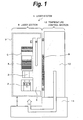
- Fig. 1 is a schematic diagram showing the structure of a laser system according to a first embodiment of the present invention;
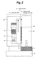
- Fig. 2 is a schematic diagram showing the structure of a laser system according to a second embodiment of the present invention;
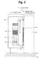
- Fig. 3 is a schematic diagram showing the structure of a laser system according to a third embodiment of the present invention;
- Fig. 4 is a schematic diagram showing the structure of a laser system according to a fourth embodiment of the present invention;
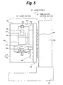
- Fig. 5 is a schematic diagram showing a specific example of the structure of a laser system;
- Fig. 6 is a schematic diagram showing a specific example of the structure of a laser system;
- Fig. 7 is a schematic diagram describing the structure of an external cavity type semiconductor laser;
- Fig. 8 is a schematic diagram showing the structure of a laser system according to the related art; and
- Fig. 9 is a schematic diagram showing the structure of the laser system shown in Fig. 8, the laser system being seen from one side.
- First, with reference to Fig. 1, the structure of a
laser system 1 according to a first embodiment of the present invention will be described. Thelaser system 1 is composed of alaser section 8 that has alaser diode 2, alens 3, agrating 4, afirst support member 5, asecond support member 6, and alid 7; and atemperature control section 12 that has aPeltier device 9, aheat sink 10, and abase plate 11. Thelaser diode 2, thelens 3, thegrating 4, and so forth are covered by thelid 7 of thelaser section 8 and thesecond support member 6. Thus, thelid 7 and thesecond support member 6 block air from entering into and exiting from thelaser section 8 so that the temperatures of thelaser diode 2, thelens 3, thegrating 4, and so forth are kept constant. - The structures of the other components of the
laser section 8 are basically the same as those of thelaser section 130 shown in Fig. 8 and Fig. 9. In the related art, the optical components such as thelaser diode 121, thelens 122, thegrating 123, and so forth are horizontally arranged on the arrangement surface of thelaser system 120. In contrast, according to the first embodiment, the optical components are arranged perpendicular to the arrangement surface of thelaser system 1. - A temperature sensor (not shown) is disposed in the vicinity of the
laser diode 2. The direction and amount of the current that flows in thePeltier device 9 are decided according to temperature data obtained by the temperature sensor so that the temperature of thelaser section 8 is properly controlled. The position of the temperature sensor will be described with reference to Fig. 6. - Unlike with the related art, the
temperature control section 12 is disposed on one side of thelaser section 8. More specifically, theheat sink 10 is connected to thePeltier device 9. ThePeltier device 9 is connected to thesecond support member 6 of thelaser section 8. They need to be connected so that at least heat is transmitted therebetween for example by closely contacting them. A buffer member may be interposed between theheat sink 10 and thePeltier device 9 and between thePeltier device 9 and thesecond support member 6. Heat is transmitted between thegrating 4 and theheat sink 10 through thefirst support member 5, thesecond support member 6, and thePeltier device 9. - In such a structure, heat generated in the
laser diode 2 and so forth is transmitted to theheat sink 10 through thesecond support member 6 and thePeltier device 9. The heat is further transmitted to thebase plate 11. Since theheat sink 10 is disposed on one side of thelaser section 8, it is not heated up with heated air that rises from theheat sink 10 unlike with thelaser system 1 according to the related art. From this point, it can be said that heat of theheat sink 10 is hardly transmitted to thelaser section 8. - According to this embodiment, the
laser diode 2 is used. Instead, another type of a semiconductor laser device may be used. According to this embodiment, thePeltier device 9 is used to control the temperature of thelaser section 8. Instead, another type of a heat absorption device may be used. Instead, the temperature of thelaser section 8 may be controlled only with a heat generation device. Likewise, these devices may be used in the following embodiments. - This advantageous arrangement of the
heat sink 10 and thelaser section 8 is facilitated when thebase plate 11 is horizontally disposed against the ground. In other words, thelaser section 8 needs to be free from a path of air that is heated by theheat sink 10 and that rises. - However, according to the first embodiment, there is a possibility of which heat is transmitted to the
laser section 8 on a route denoted by arrow C. When thelaser section 8 is set at -10 °C against the ambient temperature, theheat sink 10 is heated up by 40 °C or higher through thePeltier device 9. The heat is transmitted to thebase plate 11 on the route denoted by arrow C. The heat also heats up thelid 7 through air interposed between thebase plate 11 and thelid 7. Thus, thelaser section 8 is indirectly heated up by the heat of thelid 7. - In this case, although the
laser section 8 is cooled down by thePeltier device 9 as described above, since the amount of heat transmitted on the route denoted by arrow C is much larger than the amount of heat cooled down by thePeltier device 9, thelaser section 8 is heated up. - However, this situation can be solved when the
base plate 11 and thelid 7 shown in Fig. 1 are spaced apart by predetermined distance D. When thelaser section 8 is set at -10 °C against the ambient temperature, if the distance D is around 10 mm or more, heat transmitted from thebase plate 11 to thelid 7 can be remarkably decreased. When thelaser section 8 is set at -10 °C against the ambient temperature, it is expected that thelaser system 1 is used for a holography memory writer. When thelaser section 8 is excessively cooled down, it should be noted that heat generated in theheat sink 10 may adversely affect other than thelaser section 8. - When the
laser section 8 is heated up, even if thelaser section 8 is set at +20 °C against the ambient temperature, the distance D needs to be around 5 mm. Since the temperature of theheat sink 10 does not decrease by at most 5 °C against the ambient temperature, cold air transmitted to thelaser section 8 on the route denoted by arrow C is small. - The
lid 7 is made of a material that has a heat insulation effect, namely a material that has low thermal conductivity, such as heat resistance plastic. As the thickness of thelid 7 is decreased, the heat insulation effect is improved. - Next, with reference to Fig. 2, the structure of a
laser system 21 according to a second embodiment of the present invention will be described. In thelaser system 1 according to the first embodiment, heat is transmitted on the route denoted by arrow C shown in Fig. 1. Thus, there is a heat source below thelaser section 8. In contrast, according to the second embodiment, a heat insulation member is disposed below a heat sink to block heat from being transmitted to a laser section. - The
laser system 21 is composed of alaser section 27 that has alaser diode 22, alens 23, a grating 24, asecond support member 25, and alid 26; and atemperature control section 32 that has aPeltier device 28, aheat sink 29, aheat insulation member 31, and abase plate 30. The structure of thelaser system 21 according to the second embodiment is the same as the structure of thelaser system 1 according to the first embodiment except that a part of thebase plate 30 is theheat insulation member 31. - The
heat insulation member 31 blocks heat from being transmitted on the route denoted by arrow C shown in Fig. 1 (namely, theheat insulation member 31 blocks heat generated in theheat sink 29 from being transmitted in the direction denoted by arrow E). Theheat insulation member 31 may be made of a material having a heat insulation effect, namely low thermal conductivity. The material of theheat insulation member 31 is for example foamed plastic. Instead, theheat insulation member 31 may be made of a combination of several types of materials. - However, like the first embodiment, to prevent heat generated in the
base board 30 from heating up thelaser section 27, it is preferred that the distance D by which thelaser section 27 and thebase board 30 are spaced apart be 10 mm or more. - In addition, since the
heat insulation member 31 blocks heat from escaping, the temperature of theheat sink 29 becomes high. As a result, the temperature of thelaser section 27 may not be properly controlled. However, in such a situation, when thelaser section 27 is set at +20 °C against the ambient temperature, the temperature of thelaser section 27 can be properly controlled. Since the temperature of theheat sink 29 does not lower by at most 5 °C against the ambient temperature, theheat insulation member 31 effectively blocks cold air from being transmitted to thelaser section 8. - Next, with reference to Fig. 3, the structure of a
laser system 41 according to a third embodiment of the present invention will be described. Thelaser system 1 according to the first embodiment and thelaser system 21 according to the second embodiment have thebase plates heat sink 49 is directly mounted on asurface plate 50 or the like. In this case, heat is transmitted to alaser section 47 through thesurface plate 50 or the like on the same route denoted by arrow C shown in Fig. 1. Thus, the distance D by which thelaser section 47 and thesurface plate 50 are spaced apart needs to be 10 mm or more. - The surface plate is a flat plate or block that has an accurately flat surface. The surface plate is used to accurately align a measurement instrument and so forth.
- The other structure of the
laser system 41 according to the third embodiment is the same as that of thelaser system 1 according to the first embodiment. In other words, thelaser system 41 is composed of thelaser system 47 that has alaser diode 42, alens 43, a grating 44, asecond support member 45, and alid 46; and atemperature control section 52 that has aPeltier device 48, theheat sink 49, and thesurface plate 50. - Next, with reference to Fig. 4, the structure of a
laser system 61 according to a fourth embodiment of the present invention will be described. Thelaser system 61 according to this embodiment is a modification of thelaser system 1 according to the first embodiment. In other words, aheat insulation member 72 is inserted into the space formed between a lower portion of thelid 7, which covers thelaser section 8, and an upper portion of thebase plate 11. Theheat insulation member 72 effectively blocks heat from being transmitted on the route denoted by arrow C shown in Fig. 1. Theheat insulation member 72 may be made of the same material as theheat insulation member 31 used in thelaser system 21 according to the second embodiment. - In addition, a heat insulation member may be inserted into the similar space formed between the laser section and the base board of the laser system according to each of the first to third embodiments to block heat from being transmitted to the laser section.
- Fig. 5 shows a specific example of a
laser system 81 that has a structure similar to the structure of thelaser system 1 according to the first embodiment shown in Fig. 1. Fig. 5 shows a more specific structure of a laser section of thelaser system 81. The orientation of reflected light of a grating 84 is the reverse of that of the foregoing laser systems. Fig. 6 is a side view showing thelaser system 81 seen from the direction denoted by arrow F. Arrow G shown in Fig. 6 represents a path of light reflected by thegrating 84. Fig. 5 shows thelaser system 81 seen from the rear of the reflection surface of the grating 84. - The detailed structure of the laser section of the
laser system 81 is different from the detailed structure of the laser section of thelaser system 1 according to the first embodiment. The essence of the present invention is a structure of which heat generated in the laser section is effectively cooled down and the laser section is miniaturized. The laser section of the laser system according to each of the foregoing embodiments may be structured in various manners, not limited to those shown in the foregoing drawings. Thus, the specific structure of the laser section shown in Fig. 5 and Fig. 6 is just an example. - The
laser system 81 is composed of alaser section 87 that has alaser diode 82, alens 83, a grating 84, asecond support member 85, alid 86, and atemperature sensor 92 that measures the temperature of the laser section; and atemperature control section 91 that has aPeltier device 88, aheat sink 89, and abase plate 90. - In the
laser section 87 of thelaser system 81 according to this embodiment, thelaser diode 82 does not have a window glass. The lens (collimate lens) 83 and thelaser diode 82 block the light emission surface of thelaser diode 82 from exposing to external air. In this structure, single mode laser light is emitted. - To keep the temperature of the
laser section 87 constant, temperature detection means such as atemperature sensor 92 that measures the temperature of thelaser section 87 is essential. While the value of temperature data obtained by thetemperature sensor 92 is being monitored, the direction and amount of the current that flows to thePeltier device 88 are adjusted. - Next, the more specific structural portions shown in Fig. 5 and Fig. 6 will be described. A
column 95 for a gratingangle adjustment screw 94 is mounted on a mounting base designated byreference numeral 93. Areception member 96 that receives the tip of the gratingangle adjustment screw 94 and that is made of a metal is mounted on agrating holder 97. Thegrating holder 97 is disposed on the mountingbase 93. - The
grating holder 97 is mounted at one end of aleaf spring 98. The other end of theleaf spring 98 is mounted on acolumn 99. Thecolumn 99 is mounted on the mountingbase 93. By turning the gratingangle adjustment screw 94, the angle of the grating 84 supported by thegrating holder 97 can be adjusted. - The modifications according to the second to fourth embodiments may be applied to the
laser system 81 shown in Fig. 5 and Fig. 6. Thelaser system 81 modified according to the second to fourth embodiments has the same effects as the second to fourth embodiments.
Claims (20)
- A laser system, comprising:a base plate;a heat sink that is connected to the base plate and that is nearly perpendicular thereto;a heat generation device or a heat absorption device that is connected to the heat sink and that is nearly perpendicular to the base plate; anda laser section that is connected to the heat generation device or the heat absorption device and that is nearly perpendicular to the base plate, one surface of the heat generation device or the heat absorption device being connected to the laser section, the other surface of the heat generation device or the heat absorption device being connected to the heat sink,wherein the laser section has a semiconductor laser device, a lens, a grating, and a support member, the semiconductor laser device, the lens, and the grating composing an external cavity type semiconductor laser, the support member supporting the external cavity type semiconductor laser,wherein the laser section is connected to the heat generation device or the heat absorption device connected to the heat sink by the support member, andwherein the external cavity type semiconductor laser is covered by the support member and a lid that has heat resistance.
- The laser system as set forth in claim 1,
wherein the base plate and the heat sink are connected through a heat insulation member. - The laser system as set forth in claim 1,
wherein a space is formed between the base plate and the laser section, the space having a predetermined height. - The laser system as set forth in claim 3,
wherein the predetermined height is at least 10 mm. - The laser system as set forth in claim 4,
wherein a heat insulation member is disposed in the space having the predetermined height. - The laser system as set forth in claim 2,
wherein a space is formed between the base plate and the laser section, the space having a predetermined height. - The laser system as set forth in claim 6,
wherein the predetermined height is at least 10 mm. - The laser system as set forth in claim 7,
wherein a heat insulation member is disposed in the space having the predetermined height. - The laser system as set forth in claim 1,
wherein the heat generation device or the heat absorption device is a Peltier device. - The laser system as set forth in claim 1, further comprising:temperature detection means for detecting the temperature of the laser section.
- A laser system, comprising:a heat sink that is directly connected to a surface plate and that is nearly perpendicular to the surface plate;a heat generation device or a heat absorption device that is connected to the heat sink and that is nearly perpendicular to the surface plate; anda laser section that is connected to the heat generation device or the heat absorption device and that is nearly perpendicular to the surface plate, one surface of the heat generation device or the heat absorption device being connected to the laser section, the other surface of the heat generation device or the heat absorption device being connected to the heat sink,wherein the laser section has a semiconductor laser device, a lens, a grating, and a support member, the semiconductor laser device, the lens, and the grating composing an external cavity type semiconductor laser, the support member supporting the external cavity type semiconductor laser,wherein the laser section is connected to the heat generation device or the heat absorption device connected to the heat sink by the support member, andwherein the external cavity type semiconductor laser is covered by the support member and a lid that has heat resistance.
- The laser system as set forth in claim 11,
wherein the surface plate and the heat sink are connected through a heat insulation member. - The laser system as set forth in claim 11,
wherein a space is formed between the surface plate and the laser section, the space having a predetermined height. - The laser system as set forth in claim 13,
wherein the predetermined height is at least 10 mm. - The laser system as set forth in claim 14,
wherein a heat insulation member is disposed in the space having the predetermined height. - The laser system as set forth in claim 12,
wherein a space is formed between the surface plate and the laser section, the space having a predetermined height. - The laser system as set forth in claim 16,
wherein the predetermined height is at least 10 mm. - The laser system as set forth in claim 17,
wherein a heat insulation member is disposed in the space having the predetermined height. - The laser system as set forth in claim 11,
wherein the heat generation device or the heat absorption device is a Peltier device. - The laser system as set forth in claim 11, further comprising:temperature detection means for detecting the temperature of the laser section.
Applications Claiming Priority (2)
| Application Number | Priority Date | Filing Date | Title |
|---|---|---|---|
| JP2003397000A JP2005159104A (en) | 2003-11-27 | 2003-11-27 | Laser system |
| PCT/JP2004/017217 WO2005053123A1 (en) | 2003-11-27 | 2004-11-12 | Laser system |
Publications (1)
| Publication Number | Publication Date |
|---|---|
| EP1689055A1 true EP1689055A1 (en) | 2006-08-09 |
Family
ID=34631528
Family Applications (1)
| Application Number | Title | Priority Date | Filing Date |
|---|---|---|---|
| EP04819329A Withdrawn EP1689055A1 (en) | 2003-11-27 | 2004-11-12 | Laser system |
Country Status (6)
| Country | Link |
|---|---|
| US (1) | US20070036185A1 (en) |
| EP (1) | EP1689055A1 (en) |
| JP (1) | JP2005159104A (en) |
| KR (1) | KR20060116802A (en) |
| CN (1) | CN1883088A (en) |
| WO (1) | WO2005053123A1 (en) |
Cited By (3)
| Publication number | Priority date | Publication date | Assignee | Title |
|---|---|---|---|---|
| EP2072990A3 (en) * | 2007-12-20 | 2010-12-01 | Daylight Solutions, Inc. | Gas imaging system |
| US9731381B2 (en) | 2013-11-22 | 2017-08-15 | Salvagnini Italia S.P.A. | Laser cutting head for machine tool |
| EP3540877A1 (en) * | 2018-03-12 | 2019-09-18 | Guangdong Oppo Mobile Telecommunications Corp., Ltd | Laser projection module, depth camera and electronic device |
Families Citing this family (13)
| Publication number | Priority date | Publication date | Assignee | Title |
|---|---|---|---|---|
| JP4461387B2 (en) | 2005-12-12 | 2010-05-12 | ソニー株式会社 | Holographic recording medium, holographic recording system, and holographic reproducing system |
| JP5534306B2 (en) * | 2009-09-29 | 2014-06-25 | カシオ計算機株式会社 | Semiconductor light source device and projector |
| CN101810912B (en) * | 2010-04-02 | 2013-02-20 | 沈阳碧根医疗器械有限公司 | Laser diode assembly |
| CN102136668A (en) * | 2011-03-06 | 2011-07-27 | 四川大学 | Temperature control method of laser medium of disk laser and device thereof |
| JP6146335B2 (en) * | 2014-02-17 | 2017-06-14 | ソニー株式会社 | Scanning unit, laser scanning microscope and temperature control method |
| JP6318802B2 (en) * | 2014-04-17 | 2018-05-09 | 日本電気株式会社 | Laser module |
| CN107005026A (en) * | 2014-12-12 | 2017-08-01 | 日本电气株式会社 | Variable wavelength laser equipment |
| CN104795726B (en) * | 2015-05-05 | 2018-04-20 | 中国科学院武汉物理与数学研究所 | Semiconductor laser device capable of working below zero degree centigrade in integral refrigeration |
| JP7033068B2 (en) | 2016-09-05 | 2022-03-09 | 古河電気工業株式会社 | Laser device and light source device |
| JP6844994B2 (en) * | 2016-11-25 | 2021-03-17 | 古河電気工業株式会社 | Laser device and light source device |
| JP6844993B2 (en) | 2016-11-25 | 2021-03-17 | 古河電気工業株式会社 | Laser device and light source device |
| WO2021024046A1 (en) * | 2020-04-16 | 2021-02-11 | Владимир ВАХ | Module of a temperature regulating device for a semiconductor laser |
| CN115566531B (en) * | 2022-09-08 | 2023-08-15 | 北京融为科技有限公司 | Laser transceiver with high-reliability temperature control structure and optical telescope |
Family Cites Families (10)
| Publication number | Priority date | Publication date | Assignee | Title |
|---|---|---|---|---|
| JPH0645705A (en) * | 1992-07-24 | 1994-02-18 | Fujitsu Ltd | Laser module |
| JPH11233894A (en) * | 1998-02-18 | 1999-08-27 | Furukawa Electric Co Ltd:The | Tunable external cavity laser |
| US6252726B1 (en) * | 1999-09-02 | 2001-06-26 | Lightlogic, Inc. | Dual-enclosure optoelectronic packages |
| JP2001094205A (en) * | 1999-09-20 | 2001-04-06 | Sumitomo Electric Ind Ltd | Light emitting device, method for generating signal light, method for transmitting signal light, optical communication system, and method for determining isolation value |
| JP2001144362A (en) * | 1999-11-15 | 2001-05-25 | Sigma Koki Kk | Semiconductor laser device and manufacturing method therefor |
| JP2001332806A (en) * | 2000-03-16 | 2001-11-30 | Konica Corp | Laser exposer |
| AU2001257256A1 (en) * | 2000-05-03 | 2001-11-12 | Perceptual Robotics, Inc. | Camera network management system |
| JP2002141608A (en) * | 2000-11-02 | 2002-05-17 | Furukawa Electric Co Ltd:The | Semiconductor laser module and Raman amplifier using it |
| JP2002148489A (en) * | 2000-11-07 | 2002-05-22 | Furukawa Electric Co Ltd:The | Semiconductor laser module and Raman amplifier using the semiconductor laser module |
| JP2003142767A (en) * | 2001-10-31 | 2003-05-16 | Furukawa Electric Co Ltd:The | Laser module |
-
2003
- 2003-11-27 JP JP2003397000A patent/JP2005159104A/en not_active Abandoned
-
2004
- 2004-11-12 EP EP04819329A patent/EP1689055A1/en not_active Withdrawn
- 2004-11-12 KR KR1020067006211A patent/KR20060116802A/en not_active Withdrawn
- 2004-11-12 US US10/573,180 patent/US20070036185A1/en not_active Abandoned
- 2004-11-12 WO PCT/JP2004/017217 patent/WO2005053123A1/en not_active Ceased
- 2004-11-12 CN CNA2004800335813A patent/CN1883088A/en active Pending
Non-Patent Citations (1)
| Title |
|---|
| See references of WO2005053123A1 * |
Cited By (4)
| Publication number | Priority date | Publication date | Assignee | Title |
|---|---|---|---|---|
| EP2072990A3 (en) * | 2007-12-20 | 2010-12-01 | Daylight Solutions, Inc. | Gas imaging system |
| US9731381B2 (en) | 2013-11-22 | 2017-08-15 | Salvagnini Italia S.P.A. | Laser cutting head for machine tool |
| EP3540877A1 (en) * | 2018-03-12 | 2019-09-18 | Guangdong Oppo Mobile Telecommunications Corp., Ltd | Laser projection module, depth camera and electronic device |
| US11082671B2 (en) | 2018-03-12 | 2021-08-03 | Guangdong Oppo Mobile Telecommunications Corp., Ltd. | Laser projection module, depth camera and electronic device |
Also Published As
| Publication number | Publication date |
|---|---|
| US20070036185A1 (en) | 2007-02-15 |
| WO2005053123A1 (en) | 2005-06-09 |
| JP2005159104A (en) | 2005-06-16 |
| CN1883088A (en) | 2006-12-20 |
| KR20060116802A (en) | 2006-11-15 |
Similar Documents
| Publication | Publication Date | Title |
|---|---|---|
| EP1689055A1 (en) | Laser system | |
| US20100002235A1 (en) | Laser diode arrangements and method for gas detection | |
| CN103852835B (en) | Optical module and optical transmission method | |
| JP2763980B2 (en) | Optical semiconductor module | |
| JP2003218446A (en) | Optical modules and optical components | |
| JPH06215398A (en) | Temperature-compensated optical assembly | |
| JP2735391B2 (en) | Device for holding a cylindrical laser tube so that the radiation direction is stable | |
| US10935425B2 (en) | Spectroscopic detector | |
| JP2004253779A (en) | Optical transmitter | |
| TWI661627B (en) | Optical fiber cooling device and laser oscillator | |
| US7283302B2 (en) | Wavelength filter and wavelength monitor device | |
| US20080291954A1 (en) | Optical Projection System and Method for a Cooled Light Source | |
| JPH07302949A (en) | Wavelength stabilizing device | |
| JP2006324524A (en) | Light emitting module | |
| JPH07273393A (en) | Wavelength stabilizer | |
| JP4067167B2 (en) | Beam axis deviation detecting device and beam axis position control device for laser resonator | |
| JPH08186322A (en) | Laser equipment | |
| JP3678439B2 (en) | Wavelength stabilizer | |
| JPS62277783A (en) | Laser beam source device | |
| WO2022244440A1 (en) | Optical module and optical module system | |
| JP2681319B2 (en) | Laser oscillator | |
| JP2004179427A (en) | Semiconductor laser laser output wavelength control method and semiconductor laser oscillation device | |
| JPH04336481A (en) | Semiconductor laser with temperature control device | |
| CN119384775A (en) | Laser device | |
| JP4586846B2 (en) | Optical transmitter |
Legal Events
| Date | Code | Title | Description |
|---|---|---|---|
| PUAI | Public reference made under article 153(3) epc to a published international application that has entered the european phase |
Free format text: ORIGINAL CODE: 0009012 |
|
| 17P | Request for examination filed |
Effective date: 20060329 |
|
| AK | Designated contracting states |
Kind code of ref document: A1 Designated state(s): DE GB |
|
| DAX | Request for extension of the european patent (deleted) | ||
| RBV | Designated contracting states (corrected) |
Designated state(s): DE GB |
|
| STAA | Information on the status of an ep patent application or granted ep patent |
Free format text: STATUS: THE APPLICATION HAS BEEN WITHDRAWN |
|
| 18W | Application withdrawn |
Effective date: 20070822 |