EP1688807B2 - Verfahren zur Bewegungsaufteilung einer Relativbewegung zwischen einem Werkstück und einem Werkzeug einer Werkzeugmaschine - Google Patents
Verfahren zur Bewegungsaufteilung einer Relativbewegung zwischen einem Werkstück und einem Werkzeug einer Werkzeugmaschine Download PDFInfo
- Publication number
- EP1688807B2 EP1688807B2 EP05002414.0A EP05002414A EP1688807B2 EP 1688807 B2 EP1688807 B2 EP 1688807B2 EP 05002414 A EP05002414 A EP 05002414A EP 1688807 B2 EP1688807 B2 EP 1688807B2
- Authority
- EP
- European Patent Office
- Prior art keywords
- closed
- axis control
- axis
- control
- loop
- Prior art date
- Legal status (The legal status is an assumption and is not a legal conclusion. Google has not performed a legal analysis and makes no representation as to the accuracy of the status listed.)
- Expired - Lifetime
Links
- 230000033001 locomotion Effects 0.000 title claims abstract description 54
- 238000000034 method Methods 0.000 title claims abstract description 13
- 230000006978 adaptation Effects 0.000 claims description 7
- 230000033228 biological regulation Effects 0.000 abstract description 7
- 238000003754 machining Methods 0.000 description 4
- 230000001052 transient effect Effects 0.000 description 4
- 238000003698 laser cutting Methods 0.000 description 3
- 230000001133 acceleration Effects 0.000 description 2
- 230000000694 effects Effects 0.000 description 2
- 238000005259 measurement Methods 0.000 description 2
- 230000001105 regulatory effect Effects 0.000 description 2
- 238000004590 computer program Methods 0.000 description 1
- 238000005520 cutting process Methods 0.000 description 1
- 230000007423 decrease Effects 0.000 description 1
- 238000001514 detection method Methods 0.000 description 1
- 238000009826 distribution Methods 0.000 description 1
- 230000002349 favourable effect Effects 0.000 description 1
- 238000004519 manufacturing process Methods 0.000 description 1
- 230000010355 oscillation Effects 0.000 description 1
Images


Classifications
-
- G—PHYSICS
- G05—CONTROLLING; REGULATING
- G05B—CONTROL OR REGULATING SYSTEMS IN GENERAL; FUNCTIONAL ELEMENTS OF SUCH SYSTEMS; MONITORING OR TESTING ARRANGEMENTS FOR SUCH SYSTEMS OR ELEMENTS
- G05B19/00—Programme-control systems
- G05B19/02—Programme-control systems electric
- G05B19/18—Numerical control [NC], i.e. automatically operating machines, in particular machine tools, e.g. in a manufacturing environment, so as to execute positioning, movement or co-ordinated operations by means of programme data in numerical form
- G05B19/19—Numerical control [NC], i.e. automatically operating machines, in particular machine tools, e.g. in a manufacturing environment, so as to execute positioning, movement or co-ordinated operations by means of programme data in numerical form characterised by positioning or contouring control systems, e.g. to control position from one programmed point to another or to control movement along a programmed continuous path
- G05B19/39—Numerical control [NC], i.e. automatically operating machines, in particular machine tools, e.g. in a manufacturing environment, so as to execute positioning, movement or co-ordinated operations by means of programme data in numerical form characterised by positioning or contouring control systems, e.g. to control position from one programmed point to another or to control movement along a programmed continuous path using a combination of the means covered by at least two of the preceding groups G05B19/21, G05B19/27 and G05B19/33
-
- G—PHYSICS
- G05—CONTROLLING; REGULATING
- G05B—CONTROL OR REGULATING SYSTEMS IN GENERAL; FUNCTIONAL ELEMENTS OF SUCH SYSTEMS; MONITORING OR TESTING ARRANGEMENTS FOR SUCH SYSTEMS OR ELEMENTS
- G05B2219/00—Program-control systems
- G05B2219/30—Nc systems
- G05B2219/41—Servomotor, servo controller till figures
- G05B2219/41457—Superposition of movement
-
- G—PHYSICS
- G05—CONTROLLING; REGULATING
- G05B—CONTROL OR REGULATING SYSTEMS IN GENERAL; FUNCTIONAL ELEMENTS OF SUCH SYSTEMS; MONITORING OR TESTING ARRANGEMENTS FOR SUCH SYSTEMS OR ELEMENTS
- G05B2219/00—Program-control systems
- G05B2219/30—Nc systems
- G05B2219/42—Servomotor, servo controller kind till VSS
- G05B2219/42225—Coarse and fine position control combined, added, superposed
Definitions
- the invention relates to a method for motion distribution with the features of the preamble of claim 1 Furthermore, the invention relates device-wise a machine tool having the features of the preamble of claim 5.
- Such a method and such a machine tool are for example from EP 0 594 699 B1 known.
- a tool holder can be provided on a portal that can be moved in the Y direction via a drive, which can be moved along the portal by way of a second drive for a short distance in the Y direction.
- a tool held on the tool holder can thereby be moved via two drives in the Y direction.
- the first drive driving the portal is abbreviated as machine axis and the second, higher dynamic drive, referred to as additional axis.
- a drive moving the workpiece in an axial direction is often referred to as a workpiece axis. With axis so often acting in the axial direction drive is called.
- the additional axis can be a machine axis or a workpiece axis. The control or regulation of two acting in the same axial direction drives can turn out to be difficult.
- the control signal indicates the necessary total movement to be performed.
- the device splits the signal into moving parts of the tool carrier (low dynamic axis) and an additional device (higher dynamic axis).
- the division on the two axes of movement is carried out by an electronic filter, wherein the control signal components for the tool carrier are generated by a low-pass and the control signal components for the additional device by a high pass.
- the CNC controller receives feedback signals describing the total motion in one axis direction.
- the object of the present invention is to provide a method for dividing components of movement or a machine tool with which a higher accuracy and greater dynamics in the machining of workpieces can be achieved.
- the higher dynamic axis is set.
- the higher dynamic axis additionally increases the following error of the lower dynamic axis. This reduces the deviation of the mechanically connected in series axes.
- a first input variable for a controller of the first axis control for the first motion component is determined from the target size for the total motion, a size of the first axis control is determined and taking into account this size, a second input variable for a controller the second axis control is determined for the second motion component.
- the size of the first axis control can thus be fed directly to the second axis control.
- the second axis control it can be fed to the regulator of the second axis control directly or after further processing and / or comparison with another variable.
- the quantity supplied to the second axis control can be, for example, the input variable of the regulator of the first axis control or the actual variable determined at the output of a first controlled system of the first axis control.
- a stationary favorable operating point is achieved if in the first axis control a position control for a first acting in an axial direction drive and in the second axis control a tracking control for a second acting in the same axial direction drive is performed.
- an actual size of the total motion is determined and from this actual size and the target size for the total movement, the first input variable is determined, a tracking offset is specified and the second input from the tracking offset and the actual Size of a first controlled system of the first axis control is determined.
- the axes or axle drives for realizing the first and second components of movement are mechanically connected in series.
- the target size is exclusively for the first axis control.
- a control signal for the higher dynamic axis (the higher dynamic drive) is determined.
- the actual size of the higher dynamic axis is used as the actual value and regulates this to a predefinable value (trailing offset) by generating a control signal for the drive of the lower dynamic axis.
- the position error of the first drive can be reduced if in each case a position control for a final drive is performed in the first and second axis control, being set by the second axis control of the following error (deviation from target value and actual value) of the first axis control.
- the first input variable of the regulator of the first axis control is determined from the desired value for the total movement and the actual variable of a first controlled system of the first axis control.
- the input variable of the controller of the first axis control is the position error in the control of the low dynamic axis. This position error goes as a position setpoint to the second axis control.
- the scope of the invention also includes a machine tool having the features of claim 5. With such a machine tool, the movements in the direction of an axis can not only be controlled but also regulated. This results in a higher dynamics and accuracy.
- a final drive higher dynamics is realized than by the other final drive.
- Small, fast movements can be performed by the axle drive with the higher dynamics (additional axle).
- the final drive with the higher dynamics fine adjustment can take place.
- the movements of the final drives or the movements caused by them can overlap.
- At least one axis control has a position controller.
- a control signal can be generated, which can be used to control a drive, in particular a control system having the drive.
- measuring devices for detecting the actual size in particular IstPosition or actual acceleration of the tool or workpiece.
- These actual variables can be detected for each drive, so that, for example, there is a position value for the position of the portal drive and a position value for the position of the tool or tool holder.
- the first axis control has the position controller and the higher dynamic final drive
- the second axis control has a tracking controller and the input of the follower from the detected actual size of the first controlled system of the first axis control and a predetermined tracking offset is determined. Due to the axle drive lower dynamics, a small control bandwidth can be realized. Due to the higher dynamic axis drive (additional axis), a larger control bandwidth and thus greater accuracy can be realized. The higher-dynamic final drive can only realize movements over relatively short distances, but a more precise setting can be made for this.
- a secondary condition of the control preferably provides that the higher dynamic axis is preferably held in a central position (relative to the tool length or the stroke that can be executed by the tool).
- the first axis control has the position controller and the lower-dynamic final drive and the second axis controller has a second position controller.
- This adjustment system thus has only position controller.
- a follower is not provided.
- the position error in the control of the lower dynamic axis goes as a position setpoint to the position controller of the higher dynamic axis.
- the input variable of the regulator of the first axis control is preferably formed from the setpoint variable and the actual variable of the first controlled system of the first axis control. It is particularly preferred if the setting device has an adjusting device, which is supplied with the first input variable from the first axis control.
- the first input variable is modified with an adaptation factor in a non-inventive arrangement.
- the regulation operates as follows: the lower dynamic axis can follow the position command values only to a limited extent. This sets a following error in the lower dynamic axis. This following error is fed as setpoint into the axis control of the higher dynamic axis. Although this axis can follow their setpoints only conditionally, but much better than the lower dynamic axis. As a result, the higher dynamic axis reduces the deviations of the lower dynamic axis. The higher dynamic axis only compensates for errors of the lower dynamic axis, even those deviations which act on the lower dynamic axis due to disturbing forces.
- the oscillator described above in the following error has a very unfavorable effect on the resulting path movement.
- the deviations may be higher than if only the lower dynamic axis is operated alone, although their stationary position deviation is higher than with the coupled axes!
- Y-axis is higher dynamic than the X-axis.
- the X and X2 axes must together have the same control behavior as the Y axis in order to achieve the lowest possible path errors.
- This adaptation is done according to the invention by an adjustment factor lying between zero and one from the following error of the lower dynamic axis (in the example: X-axis) to the desired value of the higher dynamic axis (in the example X2-axis).
- This factor ensures that the higher dynamic axis can not completely compensate for the positional error even in stationary.
- the coupled axes act with the correct setting of the matching factor exactly the same as the other (n) axes in the rail network (in the example, the Y axis), provided that they have a common P-position control.
- the adjustment factor ultimately reduces the effect of the higher dynamic axis to the level required for good track performance.
- the oscillator decreases in the positional deviation of the coupled axes, or it disappears completely.
- the matching factor is a good way to meet the above conditions for a good track behavior.
- optimum parameterization results if the adaptation factor is set such that the positional error when driving bearing lamps in one direction of motion is barely overshooting.
- the same control behavior must be established in the X and Y directions, i. the "better" axes must be adapted to the "worse” ones by means of the described factor.
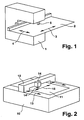
- FIG. 1 is a machine tool 1 shown, in which a workpiece 2 along the axial directions 3, 4 is movable.
- a tool holder 5, which can accommodate a tool, not shown, is also movable in the axial direction 4.
- Actuators for the workpiece, which act in the axial directions 3, 4, can be referred to as workpiece axes.
- the drive of the tool holder 5, which acts in the axial direction 4, can be referred to as the machine axis.
- FIG. 2 is another machine tool 10 shown, in which the workpiece 11 is arranged stationary.
- a portal 12 is movable along the axial direction 13.
- a device 14 is arranged, on which in turn a tool holder 14 'is arranged, which can hold a tool.
- the device 14 (and thus the tool) is movable in the axial direction 15.
- the tool holder 14 ' is movable with respect to the device 14 in the axial direction 13. From the Fig. 2 It can be seen that the device 14 has a lower mass than the portal 12. Therefore, movements in the axial direction 15 can be performed faster than movements of the portal in the axial direction 13. However, highly dynamic movements in the axial direction 13 can be performed by the tool holder 14 '.
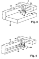
- a machine tool 20 is shown, in which an arm 21 along the axial direction 22 is movable. Along the arm 21, a device 23 in the axial direction 24 is movable. The device 23 is additionally movable in the axial direction 25.
- the axial directions 22, 24, 25 define the X, Y, Z direction of a Cartesian coordinate system.
- a boom 26 is rotatable in the axial direction 27. On the boom 26, a laser cutting head 28 is arranged, which in turn is rotatable in the axial direction 29.
- the presentation of the Fig. 4 is similar to the Fig. 3 in that the same axial directions 22, 24, 25, 27, 29 are provided.
- an axial direction 30 is provided around which a workpiece can be rotated.
- FIG. 5 Another embodiment of a machine tool is in the Fig. 5 shown.
- a device 42 in the axial direction 43 is movable.
- the device 42 is again height-adjustable in the axial direction 44.
- the boom 45 is rotatable in the axial direction 46 and the laser cutting head 47 is rotatable in the axial direction 48.
- Actuators acting in the axial directions 43, 44, 46, 48 may be referred to as machine axes, while a drive acting in the axial direction 49 may be referred to as a workpiece axis, since the workpiece 50 is movable along this axis.
- at least one second adjustment possibility must exist with respect to an axial direction. In the Fig. 5 this could be realized in that the portal 41 is also movable in the axial direction 49.
- FIG. 6 A first embodiment of an adjustment system 60 is shown.
- the adjustment system 60 is a target size x soll supplied.
- the output quantity is an actual quantity x ist .
- the adjustment system 60 has a tracking offset at the point 61.
- To from the values of x and x is in the comparator 62 is a first axis control 63 an input to a position controller 64 of the first axis control 63 determined.
- the position controller 64 determines a control signal for a controlled system 65, which has a highly dynamic additional axis.
- the thus set actual size is determined by a measuring device, not shown, as size x 1 .
- the quantities x 1 , x 2 , x can be determined, for example, from the position determination of the axes or via a distance measurement, eg between workpiece and tool. Such a distance measurement is often implemented for a distance control in a machine tool anyway.
- the tracking controller 68 and the controlled system 69 generate an increasing axis position x 2 .
- the position controller 64 reduces the axis position x 1 because it controls the sum x 1 + x 2 to the setpoint x soll .
- Fig. 7 an alternative embodiment of an adjustment system 80 is shown.
- This setting system 80 is again given a desired value x soll .
- At the output of the actual value is x.
- an input variable for a position controller 83 is determined by subtracting from the setpoint variable x soll the actual variable of the first controlled system 84 x 1 of the first axis control 81 in the comparator 82.
- the first axis controller 81 comprises the position controller 83, which generates an actuating signal for the controlled system 84 comprising one or more machine or workpiece axes, in this case of lower dynamics.
- the input variable of the position controller 83 corresponds to a positional error in the control of the axis (s) of the controlled system 84.
- This positional error is given to a matching device 85, which is arranged in a detection device 85a.
- the position error is multiplied by a factor of between 0 and 1.
- the comparator 87 the actual size x 2 at the output of the second controlled system 89 is subtracted from the output of the adaptation device 85.
- the second input variable of the position controller 88 of the second axis control 86 is generated.
- the position controller 88 determines a manipulated variable for an additional axis of the controlled system 89, in this case the higher dynamic axis.
- the actual quantities x 1 and x 2 are added to obtain the value x ist . If the positional error of the first axis control 81 enters the second axis control 86 as the setpoint value, the following error is transmitted by the additional axis of the controlled system 89 to the following error distance of the axis (n). This reduces the deviation of the mechanically interconnected first and second axes of the control paths 84, 89th
Landscapes
- Engineering & Computer Science (AREA)
- Human Computer Interaction (AREA)
- Manufacturing & Machinery (AREA)
- Physics & Mathematics (AREA)
- General Physics & Mathematics (AREA)
- Automation & Control Theory (AREA)
- Numerical Control (AREA)
- Automatic Control Of Machine Tools (AREA)
- Turning (AREA)
- Constituent Portions Of Griding Lathes, Driving, Sensing And Control (AREA)
Priority Applications (7)
| Application Number | Priority Date | Filing Date | Title |
|---|---|---|---|
| ES05002414T ES2309603T3 (es) | 2005-02-04 | 2005-02-04 | Procedimiento para la division de un movimiento relativo entre una pieza de trabajo y una herramienta de una maquina-herramienta. |
| PL05002414T PL1688807T3 (pl) | 2005-02-04 | 2005-02-04 | Sposób podziału ruchu względnego między przedmiotem obrabianym i narzędziem obrabiarki |
| AT05002414T ATE401594T1 (de) | 2005-02-04 | 2005-02-04 | Verfahren zur bewegungsaufteilung einer relativbewegung zwischen einem werkstück und einem werkzeug einer werkzeugmaschine |
| DE502005004724T DE502005004724D1 (de) | 2005-02-04 | 2005-02-04 | Verfahren zur Bewegungsaufteilung einer Relativbewegung zwischen einem Werkstück und einem Werkzeug einer Werkzeugmaschine |
| EP05002414.0A EP1688807B2 (de) | 2005-02-04 | 2005-02-04 | Verfahren zur Bewegungsaufteilung einer Relativbewegung zwischen einem Werkstück und einem Werkzeug einer Werkzeugmaschine |
| US11/346,604 US7482776B2 (en) | 2005-02-04 | 2006-02-02 | Controlling relative movement between a workpiece and a tool of a machine tool |
| JP2006026903A JP4813912B2 (ja) | 2005-02-04 | 2006-02-03 | 未加工品と工作機械の工具との間の相対運動の運動分割方法、および運動分割を実施するための工作機械 |
Applications Claiming Priority (1)
| Application Number | Priority Date | Filing Date | Title |
|---|---|---|---|
| EP05002414.0A EP1688807B2 (de) | 2005-02-04 | 2005-02-04 | Verfahren zur Bewegungsaufteilung einer Relativbewegung zwischen einem Werkstück und einem Werkzeug einer Werkzeugmaschine |
Publications (3)
| Publication Number | Publication Date |
|---|---|
| EP1688807A1 EP1688807A1 (de) | 2006-08-09 |
| EP1688807B1 EP1688807B1 (de) | 2008-07-16 |
| EP1688807B2 true EP1688807B2 (de) | 2014-06-18 |
Family
ID=34933597
Family Applications (1)
| Application Number | Title | Priority Date | Filing Date |
|---|---|---|---|
| EP05002414.0A Expired - Lifetime EP1688807B2 (de) | 2005-02-04 | 2005-02-04 | Verfahren zur Bewegungsaufteilung einer Relativbewegung zwischen einem Werkstück und einem Werkzeug einer Werkzeugmaschine |
Country Status (7)
| Country | Link |
|---|---|
| US (1) | US7482776B2 (pl) |
| EP (1) | EP1688807B2 (pl) |
| JP (1) | JP4813912B2 (pl) |
| AT (1) | ATE401594T1 (pl) |
| DE (1) | DE502005004724D1 (pl) |
| ES (1) | ES2309603T3 (pl) |
| PL (1) | PL1688807T3 (pl) |
Families Citing this family (24)
| Publication number | Priority date | Publication date | Assignee | Title |
|---|---|---|---|---|
| DE502006006615D1 (de) * | 2006-08-01 | 2010-05-12 | Trumpf Werkzeugmaschinen Gmbh | Verfahren zum koordinieren von antriebsanordnungenugehörige werkzeugmaschine |
| DE102007026356A1 (de) * | 2007-06-06 | 2009-01-08 | Trumpf Werkzeugmaschinen Gmbh + Co. Kg | Mess- oder Werkzeugmaschine mit redundanten translatorisch wirksamen Achsen zur kontinuierlichen Bewegung an komplexen Bahnkurven |
| DE102007028934A1 (de) | 2007-06-22 | 2008-12-24 | Trumpf Werkzeugmaschinen Gmbh + Co. Kg | Verfahren zur optimierten Bewegungskoordination von Mess-oder Werkzeugmaschinen mit redundanten translatorisch wirksamen Achsen |
| US7767932B2 (en) | 2007-06-29 | 2010-08-03 | Trumpf, Inc. | High dynamics laser processing machine |
| DE502007002935D1 (de) * | 2007-06-30 | 2010-04-08 | Trumpf Werkzeugmaschinen Gmbh | Werkzeugmaschine und Verfahren zum Bearbeiten eines Werkstückes |
| ATE482050T1 (de) * | 2007-06-30 | 2010-10-15 | Trumpf Werkzeugmaschinen Gmbh | Maschine zum bearbeiten von werkstücken und verfahren zum maschinellen bearbeiten von werkstücken |
| DE102007034885A1 (de) | 2007-07-14 | 2009-01-15 | Trumpf Werkzeugmaschinen Gmbh + Co. Kg | Einrichtung oder Verfahren einer Steuerung für Mess- und Werkzeugmaschinen mit redundanten translatorisch wirkenden Achsen |
| CN101556467B (zh) * | 2008-04-08 | 2012-06-13 | 深圳富泰宏精密工业有限公司 | 防止机台过冲系统及方法 |
| DE102008033709A1 (de) | 2008-07-18 | 2010-01-21 | Trumpf Werkzeugmaschinen Gmbh + Co. Kg | Verfahren zur Verlagerung der Bearbeitungsstelle eines Werkstücks und Werkzeugmaschine |
| DE102010001781A1 (de) | 2010-02-10 | 2011-08-11 | Siemens Aktiengesellschaft, 80333 | Verfahren zur Bewegung eines Maschinenelements einer Maschine aus der Automatisierungstechnik und Steuereinrichtung |
| DE102010001829B4 (de) | 2010-02-11 | 2011-09-01 | Siemens Aktiengesellschaft | Verfahren zur Bewegung eines Maschinenelements einer Maschine aus der Automatisierungstechnik und Antriebssystem |
| CN104385062A (zh) * | 2014-10-16 | 2015-03-04 | 清华大学 | 数控龙门机床 |
| DE102014116958B9 (de) | 2014-11-19 | 2017-10-05 | Trumpf Laser- Und Systemtechnik Gmbh | Optisches System zur Strahlformung eines Laserstrahls, Laserbearbeitungsanlage, Verfahren zur Materialbearbeitung und Verwenden einer gemeinsamen langgezogenen Fokuszone zur Lasermaterialbearbeitung |
| DE102014116957A1 (de) | 2014-11-19 | 2016-05-19 | Trumpf Laser- Und Systemtechnik Gmbh | Optisches System zur Strahlformung |
| EP3854513B1 (de) | 2014-11-19 | 2024-01-03 | TRUMPF Laser- und Systemtechnik GmbH | System zur asymmetrischen optischen strahlformung |
| US20180173188A1 (en) * | 2015-06-15 | 2018-06-21 | Hpt Sinergy S.R.L. | Cartesian numerically controlled machine tool for high-precision machining and optical apparatus for monitoring deformations for cartesian machine tools for high-precision machining |
| SG11201701698VA (en) | 2015-06-22 | 2017-04-27 | Electro Scient Ind Inc | Multi-axis machine tool and methods of controlling the same |
| KR102569941B1 (ko) | 2018-09-28 | 2023-08-23 | 코닝 인코포레이티드 | 투명 기판을 수정하기 위한 시스템 및 방법 |
| WO2020221410A1 (en) * | 2019-05-01 | 2020-11-05 | Kobots Aps | A portable automatic panel cutter and a method for marking panel parts |
| ES2993144T3 (en) * | 2019-05-01 | 2024-12-23 | KOBOTS Company ApS | Portable automated panel cutter |
| DE102019121827A1 (de) | 2019-08-13 | 2021-02-18 | Trumpf Laser- Und Systemtechnik Gmbh | Laserätzen mit variierender Ätzselektivität |
| AT522480B1 (de) * | 2019-11-14 | 2020-11-15 | Fill Gmbh | Verfahren zum Betreiben einer Bearbeitungsanlage |
| DK202170024A1 (en) * | 2021-01-18 | 2022-11-29 | Kobots As | Portable automated drywall board cutter |
| WO2022254639A1 (ja) * | 2021-06-02 | 2022-12-08 | ファナック株式会社 | 動作制御装置及びプログラム |
Family Cites Families (12)
| Publication number | Priority date | Publication date | Assignee | Title |
|---|---|---|---|---|
| US4382215A (en) * | 1981-07-16 | 1983-05-03 | General Electric Company | System and method of precision machining |
| DE8711811U1 (de) | 1987-09-01 | 1987-10-15 | Schmall, Karl-Heinz, 7570 Baden-Baden | Feinantrieb für ein Laserwerkzeug |
| US5109148A (en) * | 1990-01-26 | 1992-04-28 | Mitsubishi Denki Kabushiki Kaisha | Positioning device for a machining apparatus |
| JP3040448B2 (ja) * | 1990-01-26 | 2000-05-15 | 三菱電機株式会社 | 位置決め装置 |
| US5270627A (en) * | 1991-06-24 | 1993-12-14 | Unilens Corp., U.S.A. | Machine tool control system |
| DE4123323C2 (de) * | 1991-07-13 | 1994-02-10 | Andreas Ehlerding | Werkzeugträger |
| JP2735153B2 (ja) * | 1995-03-03 | 1998-04-02 | 工業技術院長 | 精密位置制御装置及び精密位置制御方法 |
| US5917300A (en) * | 1997-03-10 | 1999-06-29 | Convolve, Inc. | Method and apparatus for the control of gantry machines |
| US6835912B2 (en) * | 2002-05-28 | 2004-12-28 | Trumpf, Inc. | Laser cutting machine with two Y-axis drives |
| JP4396100B2 (ja) * | 2003-01-08 | 2010-01-13 | 株式会社安川電機 | 多軸電動機制御装置の共振周波数検出装置 |
| JP4289299B2 (ja) * | 2003-04-11 | 2009-07-01 | 三菱電機株式会社 | サーボ制御器 |
| DE10355614B4 (de) * | 2003-11-28 | 2006-11-23 | Siemens Ag | Einrichtung und Verfahren zur Bewegungsaufteilung einer Bewegung eines Maschinenteils entlang einer Antriebsachse einer Werkzeug- oder Produktionsmaschine |
-
2005
- 2005-02-04 ES ES05002414T patent/ES2309603T3/es not_active Expired - Lifetime
- 2005-02-04 DE DE502005004724T patent/DE502005004724D1/de not_active Expired - Lifetime
- 2005-02-04 AT AT05002414T patent/ATE401594T1/de not_active IP Right Cessation
- 2005-02-04 PL PL05002414T patent/PL1688807T3/pl unknown
- 2005-02-04 EP EP05002414.0A patent/EP1688807B2/de not_active Expired - Lifetime
-
2006
- 2006-02-02 US US11/346,604 patent/US7482776B2/en active Active
- 2006-02-03 JP JP2006026903A patent/JP4813912B2/ja not_active Expired - Fee Related
Also Published As
| Publication number | Publication date |
|---|---|
| ATE401594T1 (de) | 2008-08-15 |
| US7482776B2 (en) | 2009-01-27 |
| PL1688807T3 (pl) | 2009-01-30 |
| DE502005004724D1 (de) | 2008-08-28 |
| JP4813912B2 (ja) | 2011-11-09 |
| ES2309603T3 (es) | 2008-12-16 |
| EP1688807A1 (de) | 2006-08-09 |
| EP1688807B1 (de) | 2008-07-16 |
| JP2006216051A (ja) | 2006-08-17 |
| US20060176002A1 (en) | 2006-08-10 |
Similar Documents
| Publication | Publication Date | Title |
|---|---|---|
| EP1688807B2 (de) | Verfahren zur Bewegungsaufteilung einer Relativbewegung zwischen einem Werkstück und einem Werkzeug einer Werkzeugmaschine | |
| WO2008049764A1 (de) | Werkzeugmaschine | |
| DE3545795C2 (de) | Vorrichtung zur numerischen Steuerung | |
| WO2009000466A2 (de) | Verfahren zur optimierten bewegungskoordination von mess- oder werkzeugmaschinen mit redundanten translatorisch wirksamen achsen | |
| DE102016203597A1 (de) | Werkzeugmaschine und Verfahren zur maschinellen Herstellung eines Werkstücks | |
| DE3408523C2 (pl) | ||
| EP1963935B1 (de) | Ermittlungsverfahren für eine lagegeführt abzufahrende grobbahn | |
| EP2156252A1 (de) | Mess- oder werkzeugmaschine mit redundanten translatorisch wirksamen achsen zur kontinuierlichen bewegung an komplexen bahnkurven | |
| EP0931283B1 (de) | Verfahren und regelungsstruktur zur momentenvorsteuerung numerisch geregelter, elastischer und damit schwingungsfähiger mehrmassensysteme | |
| DE102012101979B4 (de) | Verfahren und Vorrichtung zur Erzeugung einer Relativbewegung | |
| DE102016012634B4 (de) | Numerische Steuerung mit krümmungs- und krümmungsänderungsabhängiger Geschwindigkeitssteuerung | |
| DE102008050863B4 (de) | Positionssteuerungsvorrichtung | |
| EP1977295B1 (de) | Verfahren zur achsregelung | |
| DE112017006003B4 (de) | Laserbearbeitungsmaschine und Laserbearbeitungssystem | |
| DE10156781C1 (de) | Aktive Kompensation von mechanischen Schwingungen und Verformungen in industriellen Bearbeitungsmaschinen | |
| EP2016471B1 (de) | Verfahren zum koordinieren von antriebsanordnungen einer werkzeugmaschine, bahnplanungseinheit und zugehörige werkzeugmaschine | |
| DE10359984B4 (de) | Verfahren und Einrichtung zur Bewegungsführung eines bewegbaren Maschinenelements einer Werkzeug- oder Produktionsmaschine | |
| EP1927906B1 (de) | Verfahren und Vorrichtung zur Lageregelung wenigstens eines Paares von Bewegungsachsen einer Maschine | |
| DE19637632A1 (de) | Numerisches Bahn-Steuersystem | |
| DE102014207170A1 (de) | Verfahren zum Freischneiden eines Werkstückteils mittels eines Laserstrahls und zugehörige Laserschneidmaschine | |
| EP1708058A1 (de) | Verfahren zur Kompensation von Überschwingern einer Hauptachse | |
| DE102005032336B4 (de) | Verfahren zur Beeinflussung einer Steuerung oder zur Steuerung einer Bewegungseinrichtung und Steuerung oder Steuerungskomponente einer Bewegungseinrichtung | |
| DE102014207220A1 (de) | Verfahren zum Laserbearbeiten eines Werkstücks mittels eines Laserstrahls und zugehörige Laserbearbeitungsmaschine | |
| EP0001269A2 (de) | Verfahren zur Bahnsteuerung einer Werkzeugmaschine | |
| DE3501487A1 (de) | Regelkreis fuer ein magnetschwebefahrzeug |
Legal Events
| Date | Code | Title | Description |
|---|---|---|---|
| PUAI | Public reference made under article 153(3) epc to a published international application that has entered the european phase |
Free format text: ORIGINAL CODE: 0009012 |
|
| 17P | Request for examination filed |
Effective date: 20060408 |
|
| AK | Designated contracting states |
Kind code of ref document: A1 Designated state(s): AT BE BG CH CY CZ DE DK EE ES FI FR GB GR HU IE IS IT LI LT LU MC NL PL PT RO SE SI SK TR |
|
| AX | Request for extension of the european patent |
Extension state: AL BA HR LV MK YU |
|
| 17Q | First examination report despatched |
Effective date: 20060821 |
|
| AKX | Designation fees paid |
Designated state(s): AT BE BG CH CY CZ DE DK EE ES FI FR GB GR HU IE IS IT LI LT LU MC NL PL PT RO SE SI SK TR |
|
| GRAP | Despatch of communication of intention to grant a patent |
Free format text: ORIGINAL CODE: EPIDOSNIGR1 |
|
| GRAS | Grant fee paid |
Free format text: ORIGINAL CODE: EPIDOSNIGR3 |
|
| GRAA | (expected) grant |
Free format text: ORIGINAL CODE: 0009210 |
|
| AK | Designated contracting states |
Kind code of ref document: B1 Designated state(s): AT BE BG CH CY CZ DE DK EE ES FI FR GB GR HU IE IS IT LI LT LU MC NL PL PT RO SE SI SK TR |
|
| REG | Reference to a national code |
Ref country code: GB Ref legal event code: FG4D Free format text: NOT ENGLISH |
|
| REG | Reference to a national code |
Ref country code: CH Ref legal event code: EP |
|
| REF | Corresponds to: |
Ref document number: 502005004724 Country of ref document: DE Date of ref document: 20080828 Kind code of ref document: P |
|
| REG | Reference to a national code |
Ref country code: IE Ref legal event code: FG4D Free format text: LANGUAGE OF EP DOCUMENT: GERMAN |
|
| REG | Reference to a national code |
Ref country code: ES Ref legal event code: FG2A Ref document number: 2309603 Country of ref document: ES Kind code of ref document: T3 |
|
| NLV1 | Nl: lapsed or annulled due to failure to fulfill the requirements of art. 29p and 29m of the patents act | ||
| PG25 | Lapsed in a contracting state [announced via postgrant information from national office to epo] |
Ref country code: LT Free format text: LAPSE BECAUSE OF FAILURE TO SUBMIT A TRANSLATION OF THE DESCRIPTION OR TO PAY THE FEE WITHIN THE PRESCRIBED TIME-LIMIT Effective date: 20080716 Ref country code: IS Free format text: LAPSE BECAUSE OF FAILURE TO SUBMIT A TRANSLATION OF THE DESCRIPTION OR TO PAY THE FEE WITHIN THE PRESCRIBED TIME-LIMIT Effective date: 20081116 Ref country code: NL Free format text: LAPSE BECAUSE OF FAILURE TO SUBMIT A TRANSLATION OF THE DESCRIPTION OR TO PAY THE FEE WITHIN THE PRESCRIBED TIME-LIMIT Effective date: 20080716 Ref country code: PT Free format text: LAPSE BECAUSE OF FAILURE TO SUBMIT A TRANSLATION OF THE DESCRIPTION OR TO PAY THE FEE WITHIN THE PRESCRIBED TIME-LIMIT Effective date: 20081216 |
|
| REG | Reference to a national code |
Ref country code: PL Ref legal event code: T3 |
|
| PG25 | Lapsed in a contracting state [announced via postgrant information from national office to epo] |
Ref country code: BG Free format text: LAPSE BECAUSE OF FAILURE TO SUBMIT A TRANSLATION OF THE DESCRIPTION OR TO PAY THE FEE WITHIN THE PRESCRIBED TIME-LIMIT Effective date: 20081016 Ref country code: SI Free format text: LAPSE BECAUSE OF FAILURE TO SUBMIT A TRANSLATION OF THE DESCRIPTION OR TO PAY THE FEE WITHIN THE PRESCRIBED TIME-LIMIT Effective date: 20080716 Ref country code: FI Free format text: LAPSE BECAUSE OF FAILURE TO SUBMIT A TRANSLATION OF THE DESCRIPTION OR TO PAY THE FEE WITHIN THE PRESCRIBED TIME-LIMIT Effective date: 20080716 |
|
| REG | Reference to a national code |
Ref country code: IE Ref legal event code: FD4D |
|
| PLBI | Opposition filed |
Free format text: ORIGINAL CODE: 0009260 |
|
| PG25 | Lapsed in a contracting state [announced via postgrant information from national office to epo] |
Ref country code: EE Free format text: LAPSE BECAUSE OF FAILURE TO SUBMIT A TRANSLATION OF THE DESCRIPTION OR TO PAY THE FEE WITHIN THE PRESCRIBED TIME-LIMIT Effective date: 20080716 Ref country code: DK Free format text: LAPSE BECAUSE OF FAILURE TO SUBMIT A TRANSLATION OF THE DESCRIPTION OR TO PAY THE FEE WITHIN THE PRESCRIBED TIME-LIMIT Effective date: 20080716 Ref country code: IE Free format text: LAPSE BECAUSE OF FAILURE TO SUBMIT A TRANSLATION OF THE DESCRIPTION OR TO PAY THE FEE WITHIN THE PRESCRIBED TIME-LIMIT Effective date: 20080716 |
|
| 26 | Opposition filed |
Opponent name: VOELKER, RENE Effective date: 20090408 |
|
| PG25 | Lapsed in a contracting state [announced via postgrant information from national office to epo] |
Ref country code: SK Free format text: LAPSE BECAUSE OF FAILURE TO SUBMIT A TRANSLATION OF THE DESCRIPTION OR TO PAY THE FEE WITHIN THE PRESCRIBED TIME-LIMIT Effective date: 20080716 Ref country code: RO Free format text: LAPSE BECAUSE OF FAILURE TO SUBMIT A TRANSLATION OF THE DESCRIPTION OR TO PAY THE FEE WITHIN THE PRESCRIBED TIME-LIMIT Effective date: 20080716 |
|
| PLAX | Notice of opposition and request to file observation + time limit sent |
Free format text: ORIGINAL CODE: EPIDOSNOBS2 |
|
| BERE | Be: lapsed |
Owner name: TRUMPF WERKZEUGMASCHINEN G.M.B.H. + CO. KG Effective date: 20090228 |
|
| PG25 | Lapsed in a contracting state [announced via postgrant information from national office to epo] |
Ref country code: MC Free format text: LAPSE BECAUSE OF NON-PAYMENT OF DUE FEES Effective date: 20090228 |
|
| GBPC | Gb: european patent ceased through non-payment of renewal fee |
Effective date: 20090204 |
|
| PLBB | Reply of patent proprietor to notice(s) of opposition received |
Free format text: ORIGINAL CODE: EPIDOSNOBS3 |
|
| PG25 | Lapsed in a contracting state [announced via postgrant information from national office to epo] |
Ref country code: SE Free format text: LAPSE BECAUSE OF FAILURE TO SUBMIT A TRANSLATION OF THE DESCRIPTION OR TO PAY THE FEE WITHIN THE PRESCRIBED TIME-LIMIT Effective date: 20081016 |
|
| PG25 | Lapsed in a contracting state [announced via postgrant information from national office to epo] |
Ref country code: BE Free format text: LAPSE BECAUSE OF NON-PAYMENT OF DUE FEES Effective date: 20090228 |
|
| PG25 | Lapsed in a contracting state [announced via postgrant information from national office to epo] |
Ref country code: GB Free format text: LAPSE BECAUSE OF NON-PAYMENT OF DUE FEES Effective date: 20090204 |
|
| PG25 | Lapsed in a contracting state [announced via postgrant information from national office to epo] |
Ref country code: AT Free format text: LAPSE BECAUSE OF NON-PAYMENT OF DUE FEES Effective date: 20090204 |
|
| PG25 | Lapsed in a contracting state [announced via postgrant information from national office to epo] |
Ref country code: GR Free format text: LAPSE BECAUSE OF FAILURE TO SUBMIT A TRANSLATION OF THE DESCRIPTION OR TO PAY THE FEE WITHIN THE PRESCRIBED TIME-LIMIT Effective date: 20081017 |
|
| PG25 | Lapsed in a contracting state [announced via postgrant information from national office to epo] |
Ref country code: LU Free format text: LAPSE BECAUSE OF NON-PAYMENT OF DUE FEES Effective date: 20090204 |
|
| PG25 | Lapsed in a contracting state [announced via postgrant information from national office to epo] |
Ref country code: HU Free format text: LAPSE BECAUSE OF FAILURE TO SUBMIT A TRANSLATION OF THE DESCRIPTION OR TO PAY THE FEE WITHIN THE PRESCRIBED TIME-LIMIT Effective date: 20090117 |
|
| PG25 | Lapsed in a contracting state [announced via postgrant information from national office to epo] |
Ref country code: CY Free format text: LAPSE BECAUSE OF FAILURE TO SUBMIT A TRANSLATION OF THE DESCRIPTION OR TO PAY THE FEE WITHIN THE PRESCRIBED TIME-LIMIT Effective date: 20080716 |
|
| PUAJ | Public notification under rule 129 epc |
Free format text: ORIGINAL CODE: 0009425 |
|
| 32PN | Public notification |
Free format text: MITTEILUNG IM EINSPRUCHSVERFAHREN (EPA FORM 2327 VOM 29/04/2013) |
|
| PUAH | Patent maintained in amended form |
Free format text: ORIGINAL CODE: 0009272 |
|
| STAA | Information on the status of an ep patent application or granted ep patent |
Free format text: STATUS: PATENT MAINTAINED AS AMENDED |
|
| PGFP | Annual fee paid to national office [announced via postgrant information from national office to epo] |
Ref country code: ES Payment date: 20140220 Year of fee payment: 10 Ref country code: PL Payment date: 20140127 Year of fee payment: 10 Ref country code: TR Payment date: 20140130 Year of fee payment: 10 |
|
| 27A | Patent maintained in amended form |
Effective date: 20140618 |
|
| AK | Designated contracting states |
Kind code of ref document: B2 Designated state(s): AT BE BG CH CY CZ DE DK EE ES FI FR GB GR HU IE IS IT LI LT LU MC NL PL PT RO SE SI SK TR |
|
| REG | Reference to a national code |
Ref country code: CH Ref legal event code: AELC |
|
| REG | Reference to a national code |
Ref country code: DE Ref legal event code: R102 Ref document number: 502005004724 Country of ref document: DE Effective date: 20140618 |
|
| PG25 | Lapsed in a contracting state [announced via postgrant information from national office to epo] |
Ref country code: ES Free format text: LAPSE BECAUSE OF FAILURE TO SUBMIT A TRANSLATION OF THE DESCRIPTION OR TO PAY THE FEE WITHIN THE PRESCRIBED TIME-LIMIT Effective date: 20140618 |
|
| REG | Reference to a national code |
Ref country code: FR Ref legal event code: PLFP Year of fee payment: 12 |
|
| PG25 | Lapsed in a contracting state [announced via postgrant information from national office to epo] |
Ref country code: PL Free format text: LAPSE BECAUSE OF NON-PAYMENT OF DUE FEES Effective date: 20150204 |
|
| REG | Reference to a national code |
Ref country code: FR Ref legal event code: PLFP Year of fee payment: 13 |
|
| PG25 | Lapsed in a contracting state [announced via postgrant information from national office to epo] |
Ref country code: TR Free format text: LAPSE BECAUSE OF NON-PAYMENT OF DUE FEES Effective date: 20150204 |
|
| REG | Reference to a national code |
Ref country code: FR Ref legal event code: PLFP Year of fee payment: 14 |
|
| PG25 | Lapsed in a contracting state [announced via postgrant information from national office to epo] |
Ref country code: PL Free format text: LAPSE BECAUSE OF FAILURE TO SUBMIT A TRANSLATION OF THE DESCRIPTION OR TO PAY THE FEE WITHIN THE PRESCRIBED TIME-LIMIT Effective date: 20080716 |
|
| PGFP | Annual fee paid to national office [announced via postgrant information from national office to epo] |
Ref country code: CZ Payment date: 20220203 Year of fee payment: 18 |
|
| PGFP | Annual fee paid to national office [announced via postgrant information from national office to epo] |
Ref country code: FR Payment date: 20230220 Year of fee payment: 19 Ref country code: CH Payment date: 20230307 Year of fee payment: 19 |
|
| PG25 | Lapsed in a contracting state [announced via postgrant information from national office to epo] |
Ref country code: CZ Free format text: LAPSE BECAUSE OF NON-PAYMENT OF DUE FEES Effective date: 20230204 |
|
| P01 | Opt-out of the competence of the unified patent court (upc) registered |
Effective date: 20240110 |
|
| PGFP | Annual fee paid to national office [announced via postgrant information from national office to epo] |
Ref country code: DE Payment date: 20240219 Year of fee payment: 20 |
|
| PGFP | Annual fee paid to national office [announced via postgrant information from national office to epo] |
Ref country code: IT Payment date: 20240228 Year of fee payment: 20 |
|
| REG | Reference to a national code |
Ref country code: CH Ref legal event code: PL |
|
| PG25 | Lapsed in a contracting state [announced via postgrant information from national office to epo] |
Ref country code: CH Free format text: LAPSE BECAUSE OF NON-PAYMENT OF DUE FEES Effective date: 20240229 |
|
| PG25 | Lapsed in a contracting state [announced via postgrant information from national office to epo] |
Ref country code: CH Free format text: LAPSE BECAUSE OF NON-PAYMENT OF DUE FEES Effective date: 20240229 |
|
| PG25 | Lapsed in a contracting state [announced via postgrant information from national office to epo] |
Ref country code: FR Free format text: LAPSE BECAUSE OF NON-PAYMENT OF DUE FEES Effective date: 20240229 |
|
| PG25 | Lapsed in a contracting state [announced via postgrant information from national office to epo] |
Ref country code: FR Free format text: LAPSE BECAUSE OF NON-PAYMENT OF DUE FEES Effective date: 20240229 |
|
| REG | Reference to a national code |
Ref country code: DE Ref legal event code: R071 Ref document number: 502005004724 Country of ref document: DE |