EP1688693A1 - Counterflow heat exchanger - Google Patents
Counterflow heat exchanger Download PDFInfo
- Publication number
- EP1688693A1 EP1688693A1 EP04792295A EP04792295A EP1688693A1 EP 1688693 A1 EP1688693 A1 EP 1688693A1 EP 04792295 A EP04792295 A EP 04792295A EP 04792295 A EP04792295 A EP 04792295A EP 1688693 A1 EP1688693 A1 EP 1688693A1
- Authority
- EP
- European Patent Office
- Prior art keywords
- heat exchanger
- tank
- outflow
- inflow
- side tank
- Prior art date
- Legal status (The legal status is an assumption and is not a legal conclusion. Google has not performed a legal analysis and makes no representation as to the accuracy of the status listed.)
- Withdrawn
Links
Images


Classifications
-
- F—MECHANICAL ENGINEERING; LIGHTING; HEATING; WEAPONS; BLASTING
- F28—HEAT EXCHANGE IN GENERAL
- F28D—HEAT-EXCHANGE APPARATUS, NOT PROVIDED FOR IN ANOTHER SUBCLASS, IN WHICH THE HEAT-EXCHANGE MEDIA DO NOT COME INTO DIRECT CONTACT
- F28D1/00—Heat-exchange apparatus having stationary conduit assemblies for one heat-exchange medium only, the media being in contact with different sides of the conduit wall, in which the other heat-exchange medium is a large body of fluid, e.g. domestic or motor car radiators
- F28D1/02—Heat-exchange apparatus having stationary conduit assemblies for one heat-exchange medium only, the media being in contact with different sides of the conduit wall, in which the other heat-exchange medium is a large body of fluid, e.g. domestic or motor car radiators with heat-exchange conduits immersed in the body of fluid
- F28D1/04—Heat-exchange apparatus having stationary conduit assemblies for one heat-exchange medium only, the media being in contact with different sides of the conduit wall, in which the other heat-exchange medium is a large body of fluid, e.g. domestic or motor car radiators with heat-exchange conduits immersed in the body of fluid with tubular conduits
- F28D1/0408—Multi-circuit heat exchangers, e.g. integrating different heat exchange sections in the same unit or heat exchangers for more than two fluids
- F28D1/0426—Multi-circuit heat exchangers, e.g. integrating different heat exchange sections in the same unit or heat exchangers for more than two fluids with units having particular arrangement relative to the large body of fluid, e.g. with interleaved units or with adjacent heat exchange units in common air flow or with units extending at an angle to each other or with units arranged around a central element
- F28D1/0435—Combination of units extending one behind the other
-
- F—MECHANICAL ENGINEERING; LIGHTING; HEATING; WEAPONS; BLASTING
- F28—HEAT EXCHANGE IN GENERAL
- F28D—HEAT-EXCHANGE APPARATUS, NOT PROVIDED FOR IN ANOTHER SUBCLASS, IN WHICH THE HEAT-EXCHANGE MEDIA DO NOT COME INTO DIRECT CONTACT
- F28D1/00—Heat-exchange apparatus having stationary conduit assemblies for one heat-exchange medium only, the media being in contact with different sides of the conduit wall, in which the other heat-exchange medium is a large body of fluid, e.g. domestic or motor car radiators
- F28D1/02—Heat-exchange apparatus having stationary conduit assemblies for one heat-exchange medium only, the media being in contact with different sides of the conduit wall, in which the other heat-exchange medium is a large body of fluid, e.g. domestic or motor car radiators with heat-exchange conduits immersed in the body of fluid
- F28D1/04—Heat-exchange apparatus having stationary conduit assemblies for one heat-exchange medium only, the media being in contact with different sides of the conduit wall, in which the other heat-exchange medium is a large body of fluid, e.g. domestic or motor car radiators with heat-exchange conduits immersed in the body of fluid with tubular conduits
- F28D1/0408—Multi-circuit heat exchangers, e.g. integrating different heat exchange sections in the same unit or heat exchangers for more than two fluids
- F28D1/0426—Multi-circuit heat exchangers, e.g. integrating different heat exchange sections in the same unit or heat exchangers for more than two fluids with units having particular arrangement relative to the large body of fluid, e.g. with interleaved units or with adjacent heat exchange units in common air flow or with units extending at an angle to each other or with units arranged around a central element
- F28D1/0452—Combination of units extending one behind the other with units extending one beside or one above the other
-
- F—MECHANICAL ENGINEERING; LIGHTING; HEATING; WEAPONS; BLASTING
- F28—HEAT EXCHANGE IN GENERAL
- F28D—HEAT-EXCHANGE APPARATUS, NOT PROVIDED FOR IN ANOTHER SUBCLASS, IN WHICH THE HEAT-EXCHANGE MEDIA DO NOT COME INTO DIRECT CONTACT
- F28D1/00—Heat-exchange apparatus having stationary conduit assemblies for one heat-exchange medium only, the media being in contact with different sides of the conduit wall, in which the other heat-exchange medium is a large body of fluid, e.g. domestic or motor car radiators
- F28D1/02—Heat-exchange apparatus having stationary conduit assemblies for one heat-exchange medium only, the media being in contact with different sides of the conduit wall, in which the other heat-exchange medium is a large body of fluid, e.g. domestic or motor car radiators with heat-exchange conduits immersed in the body of fluid
- F28D1/04—Heat-exchange apparatus having stationary conduit assemblies for one heat-exchange medium only, the media being in contact with different sides of the conduit wall, in which the other heat-exchange medium is a large body of fluid, e.g. domestic or motor car radiators with heat-exchange conduits immersed in the body of fluid with tubular conduits
- F28D1/053—Heat-exchange apparatus having stationary conduit assemblies for one heat-exchange medium only, the media being in contact with different sides of the conduit wall, in which the other heat-exchange medium is a large body of fluid, e.g. domestic or motor car radiators with heat-exchange conduits immersed in the body of fluid with tubular conduits the conduits being straight
- F28D1/0535—Heat-exchange apparatus having stationary conduit assemblies for one heat-exchange medium only, the media being in contact with different sides of the conduit wall, in which the other heat-exchange medium is a large body of fluid, e.g. domestic or motor car radiators with heat-exchange conduits immersed in the body of fluid with tubular conduits the conduits being straight the conduits having a non-circular cross-section
- F28D1/05366—Assemblies of conduits connected to common headers, e.g. core type radiators
- F28D1/05391—Assemblies of conduits connected to common headers, e.g. core type radiators with multiple rows of conduits or with multi-channel conduits combined with a particular flow pattern, e.g. multi-row multi-stage radiators
-
- F—MECHANICAL ENGINEERING; LIGHTING; HEATING; WEAPONS; BLASTING
- F28—HEAT EXCHANGE IN GENERAL
- F28F—DETAILS OF HEAT-EXCHANGE AND HEAT-TRANSFER APPARATUS, OF GENERAL APPLICATION
- F28F9/00—Casings; Header boxes; Auxiliary supports for elements; Auxiliary members within casings
- F28F9/001—Casings in the form of plate-like arrangements; Frames enclosing a heat exchange core
- F28F9/002—Casings in the form of plate-like arrangements; Frames enclosing a heat exchange core with fastening means for other structures
-
- F—MECHANICAL ENGINEERING; LIGHTING; HEATING; WEAPONS; BLASTING
- F28—HEAT EXCHANGE IN GENERAL
- F28F—DETAILS OF HEAT-EXCHANGE AND HEAT-TRANSFER APPARATUS, OF GENERAL APPLICATION
- F28F9/00—Casings; Header boxes; Auxiliary supports for elements; Auxiliary members within casings
- F28F9/26—Arrangements for connecting different sections of heat-exchange elements, e.g. of radiators
- F28F9/262—Arrangements for connecting different sections of heat-exchange elements, e.g. of radiators for radiators
-
- F—MECHANICAL ENGINEERING; LIGHTING; HEATING; WEAPONS; BLASTING
- F28—HEAT EXCHANGE IN GENERAL
- F28D—HEAT-EXCHANGE APPARATUS, NOT PROVIDED FOR IN ANOTHER SUBCLASS, IN WHICH THE HEAT-EXCHANGE MEDIA DO NOT COME INTO DIRECT CONTACT
- F28D21/00—Heat-exchange apparatus not covered by any of the groups F28D1/00 - F28D20/00
- F28D2021/0019—Other heat exchangers for particular applications; Heat exchange systems not otherwise provided for
- F28D2021/008—Other heat exchangers for particular applications; Heat exchange systems not otherwise provided for for vehicles
- F28D2021/0091—Radiators
- F28D2021/0094—Radiators for recooling the engine coolant
-
- F—MECHANICAL ENGINEERING; LIGHTING; HEATING; WEAPONS; BLASTING
- F28—HEAT EXCHANGE IN GENERAL
- F28F—DETAILS OF HEAT-EXCHANGE AND HEAT-TRANSFER APPARATUS, OF GENERAL APPLICATION
- F28F2265/00—Safety or protection arrangements; Arrangements for preventing malfunction
- F28F2265/26—Safety or protection arrangements; Arrangements for preventing malfunction for allowing differential expansion between elements
Definitions
- the present invention relates to a countercurrent heat exchanger, in which a pair of heat exchanger cores are arranged next to each other in their depth directions and coolant can flow from one of the heat exchanger cores to the other of the heat exchanger cores, turning around in an intermediate tank connected with them.
- a conventional countercurrent heat exchanger of this kind is disclosed in Japanese Patent Application Laid-open No. Tokkai 2002 - 393498.
- This countercurrent heat exchanger includes a pair of heat exchanger cores each having multiple tubes and fins arranged alternately and next to each other in its depth direction, an inflow-side tank connected with one end sides of the tubes contained in one of the heat exchanger cores, an outflow-side tank connected with one end sides of the tubes contained in the other of the heat exchanger cores, and a U-turn intermediate tank connected with the other end sides of the tubes for turning around coolant.
- the inflow-side tank and the outflow-side tank are integrally formed with each other, being separated by a separation wall between them to split off their coolant passages.
- the above-described countercurrent heat exchanger has the following problems, because the inflow-side tank and the outflow-side tank are constructed integrally with each other so that they are separated by only the separation wall provided between them.
- An object of the present invention is to provide a countercurrent heat exchanger that can avoid occurrence of a strain, a crack, destruction and the like in any part of the countercurrent heat exchanger due to heat stress caused by a temperature difference between coolants flowing in heat exchanger cores and also increase its heat transfer efficiency.
- a countercurrent heat exchanger of the present invention is constructed so that it comprises a pair of heat exchanger cores having multiple tubes and fins which are arranged alternatively, the heat exchanger cores being arranged next to each other in depth directions thereof: a U-turn intermediate tank connected with one end sides of the tubes contained in the heat exchanger cores; an inflow-side tank connected with the other end sides of the tubes contained in one of the heat exchanger cores; and an outflow-side tank formed to be separated from the inflow-side tank, the outflow-side tank being connected with the other end sides of the tubes contained in the other of the heat exchanger cores, wherein the inflow-side tank, the outflow-side tank and the intermediate tank are attached to a vehicle body side so that the both heat exchanger cores can expand and contract independently from each other with respect to the intermediate tank.
- the countercurrent heat exchanger of the present invention prevents a strain, a crack, destruction and the like from occurring in its parts due to thermal stress caused by a temperature difference between the coolants flowing in the both heat exchanger cores, since the inflow-side tank, the outflow-side tank and the intermediate tank are attached rotatably to the vehicle body member so that the heat exchanger cores can expand and contract independently from each other with respect to the intermediate tank.
- the countercurrent heat exchanger of the present invention increases the heat transfer efficiency, because it is constructed to have the inflow-side tank and the outflow-side tank which are formed separately from each other, so that heat of the coolant is prevented from being transferred from the inflow-side tank to the outflow-side tank.
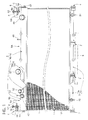
- FIG. 1 is a partially-sectional front view showing a countercuwent heat exchanger of the embodiment
- FIG. 2 is a perspective view of the same
- FIG. 3 is an enlarged plan view of the same
- FIG. 4 is an enlarged side view of the same.
- the countercurrent heat exchanger of the embodiment includes an inflow-side heat exchanger core 1, an outflow-side heat exchanger core 2, a U-turn intermediate tank 3 connecting between the both heat exchanger cores 1 and 2, an inflow-side tank 4 connected with the inflow-side heat exchanger core 1, an outflow-side tank 5 connected with the outflow-side heat exchanger core 2, a bracket 6 for supporting the heat exchanger to a vehicle-body-side, and a rubber bush 7 for supporting the intermediate tank 3 to the vehicle-body-side.
- the rubber bush 7 corresponds to an elastically supporting member of the present invention.
- the inflow-side heat exchanger core 1 and the outflow-side heat exchanger core 2 are constructed to have multiple tubes 11 and 21 in which the coolant flows and fins 12 and 22 which cools the coolant, being arranged alternatively in their lateral directions and the tubes being connected with one another. These both heat exchanger cores 1 and 2 are mounted on the vehicle body in a state in which they are disposed next to each other in their depth directions.
- the both heat exchanger cores 1 and 2 are connected at lower end sides of the tubes 11 and 21 with the U-turn intermediate tank 3, respectively, and also connected at upper end sides of the tubes 11 and 21 with the inflow-side tank 4 and the outflow-side tank 5, which are separated from each other, respectively.
- radiator core support 8 corresponds to a vehicle body member of the present invention.
- brackets 6 have heat-exchanger-side attachment portions 6a, which are attached to both the longitudinally directional end portions of the inflow-side tank 4 and the outflow-side tank 5 by bolts 61 and 61, respectively, so that the tanks 4 and 5 are rotatable around the center of the bolts 61 and 61.
- vehicle-body-side attachment portions 6b and 6b are formed to be bent, in a substantially horizontal direction and in a state where they extend toward each other, from the vertical heat-exchanger-side attachment portions 6a and 6a, respectively.
- Bolts 62 and 62 are inserted from a radiator core support 8 side and screwed into the welded nuts 6d and 6d through bushes, so that they fix the inflow-side tank 4 and the outflow-side tank 5 to the radiator core support 8 side.
- the U-turn intermediate tank 3 is elastically supported on the radiator core support 8 through the plural rubber bushes 7 and 7, which are located on a lower portion of the U-turn intermediate tank 3.
- Each inner portion of the inflow-side tank 4, the outflow-side tank 5 and the U-turn intermediate tank 3 is separated at a middle position in its longitudinal direction, thereby producing a structure combining a first radiator RA with large capacity and a second radiator RB with small capacity integrally in their lateral directions.
- First radiator RA side portions of the inflow-side tank 4a and the outflow-side tank 5a are connected with an inflow pipe 41 and an outflow pipe 51, respectively.
- second radiator RB side portions of the inflow-side tank 4a and the outflow-side tank 5a are connected with an inflow pipe 42 and an outflow pipe 52, respectively.
- the inflow-side tanks 4a and 4b are provided with air-bleeding pipes 43 and 53, respectively, and the intermediate tanks 3a and 3b are provided with drain pipes 31 and 32, respectively.
- the first radiator RA with large capacity can be used for cooling engine coolant
- the second radiator RB with small capacity can be used for cooling electric system coolant.
- FCV Fuel-Cell powered vehicle
- FCU Fan Coil Unit
- the first radiator RA with large capacity can be used for cooling heater circuits of an air conditioner, fuel-cell stacks and others
- the second radiator RB with small capacity can be used for cooling an inverter, an electric motor, other circuits and the like provided in the Fuel-Cell powered vehicle (FCV) using Long Life Coolant (LLC).
- FCV Fuel-Cell powered vehicle
- LLC Long Life Coolant
- a thermal expansion difference between the inflow-side heat exchanger cores 1 and 1 and the outflow-side heat core 2 and 2 becomes large, because the temperature difference at the first radiator RA side becomes fairly high, approximately 40°C between the coolant flowing the inflow-side heat exchanger cores 1 and 1 connected with the inflow-side tanks 4a and 4a and the coolant flowing in the outflow-side heat exchanger cores 2 and connected the outflow-side tanks 5a and 5b, and that at the second radiator RB side becomes approximately 20°C.
- the inflow-side tank 4 and the outflow-side tank 5 are formed so that they are separated from each other, and the inflow-side tank 4 and the outflow-side tank 5 are supported at its both longitudinally-directional end portions so that they are rotatable around the bolts 61 and 61 by each using one bolt 61, 61 and the bracket 6, 6 in order to attach them to the radiator core support 8, the vehicle body side.
- brackets 6 and 6 to be rotated relatively to each other at the bolts 61 and 61 with respect to the inflow-side tanks 4a and 4b and the outflow-side tanks 5a and 5b, when the inflow-side heat exchanger core 1 and the outflow-side heat exchanger core 2 expand and contract in a vertical direction with respect to the U-turn intermediate tank 3 due to a temperature change, thereby causing an expansion and contraction difference between the both heat exchanger cores 1 and 2 due to their temperature difference.
- the expansion and contraction difference can be absorbed.
- the expansion and contraction in the vertical direction of the inflow-side heat exchanger core 1 and the outflow-side heat exchanger core 2 can be absorbed by using elasticity of the rubber bushes 7, since the U-turn intermediate tank 3 is constructed so that it is elastically supported by the radiator core support 8 through a plurality of rubber bushes 7 and 7.
- the countercurrent heat exchanger of the embodiment can prevent occurrence of the strain, the crack, the destruction and the like in any portion thereof due to thermal stress caused by the temperature difference between the coolant flowing in the inflow-side heat exchanger core 1 and the coolant flowing in the outflow-side heat exchanger core 2.
- heat in the coolant flowing in the inflow-side tank 4 can be prevented from its direct transfer to the outflow-side tank 5 and heating the coolant in the outflow side, because the inflow-side tank 4 and the outflow-side tank 5 are separated from each other. Accordingly, an improvement in the heat transfer efficiency of the countercurrent heat exchanger can be obtained.
- the corrugated fin feeding apparatus of the embodiment according to the present invention has been described above, but the specific structure of the present invention is not limited to this embodiment.
- the present invention includes any change of design in the range not departing from the gist of the invention.
- each of the brackets 6 and 6 is attached by one bolt 61, 61 rotatably around the bolts 61 and 61 in the above-described embodiment, but as shown in FIG. 5, a bolt through-hole at the bracket 6 side may be formed to be an elongate hole 8a, so that the inflow-side tanks 4a and 4b and the outflow-side tanks 5a and 5b can independently slide relative to the brackets 6.
- the bolts 61 and 61 and the brackets 6 and 6 may be used so that ones of them are attached to the inflow-side tanks 4a and 4b and the outflow-side tanks 5a and 5b and the others are attached to the vehicle body side.
- inflow-side tank 4 and the outflow-side tank 5 are attached together to one bracket 6 in the embodiment, they may be attached to independent brackets, respectively.
- the rubber bushes 7 are used as an elastically supporting member for elastically supporting the U-turn intermediate tank 3 side in the above-described embodiment, they may be replaced by a leaf spring, a coil spring and the like.
- the first radiator RA with large capacity and the second radiator RB with small capacity are formed integrally in their lateral directions with each other by separation of each inner portions of the inflow-side tank 4, the outflow-side tank 5 and the U-turn immediate tank 3 at the middle position in their longitudinal directions. But, they may be constructed and used as one entire radiator without the separation like this.
- the countercurrent heat exchanger according to the present invention can be available as a heat exchanger for a motor vehicle and others such that it has a pair of heat exchangers arranged next to each other.
Landscapes
- Engineering & Computer Science (AREA)
- Physics & Mathematics (AREA)
- Thermal Sciences (AREA)
- Mechanical Engineering (AREA)
- General Engineering & Computer Science (AREA)
- Details Of Heat-Exchange And Heat-Transfer (AREA)
- Heat-Exchange Devices With Radiators And Conduit Assemblies (AREA)
- Cooling, Air Intake And Gas Exhaust, And Fuel Tank Arrangements In Propulsion Units (AREA)
Abstract
Description
- The present invention relates to a countercurrent heat exchanger, in which a pair of heat exchanger cores are arranged next to each other in their depth directions and coolant can flow from one of the heat exchanger cores to the other of the heat exchanger cores, turning around in an intermediate tank connected with them.
- A conventional countercurrent heat exchanger of this kind is disclosed in Japanese Patent Application Laid-open No. Tokkai 2002 - 393498. This countercurrent heat exchanger includes a pair of heat exchanger cores each having multiple tubes and fins arranged alternately and next to each other in its depth direction, an inflow-side tank connected with one end sides of the tubes contained in one of the heat exchanger cores, an outflow-side tank connected with one end sides of the tubes contained in the other of the heat exchanger cores, and a U-turn intermediate tank connected with the other end sides of the tubes for turning around coolant. The inflow-side tank and the outflow-side tank are integrally formed with each other, being separated by a separation wall between them to split off their coolant passages.
- However, the above-described countercurrent heat exchanger has the following problems, because the inflow-side tank and the outflow-side tank are constructed integrally with each other so that they are separated by only the separation wall provided between them.
- In a construction where the inflow-side tank and the outflow-side tank are integrally formed with each other, large thermal stress applies to the tubes, the inflow-side tank, the outflow-side tank and others, and might cause a strain, a crack, destruction and/or the like due to a thermal expansion difference caused between the both heat exchanger cores, since a thermal difference becomes large, approximately 40°C, between the coolant flowing in an inflow-side tank connected portion of the heat exchanger core and the coolant flowing in an outflow-side tank connected portion of the heat exchanger core.
- Further, high temperature coolant flowing in the inflow-side tank transfers its heat to the coolant flowing in the outflow-side tank through the separation wall to heat it up, since the inflow-side tank and the outflow-side tank are separated by only one separation wall. This decreases heat transfer efficiency of the heat exchanger cores.
- An object of the present invention is to provide a countercurrent heat exchanger that can avoid occurrence of a strain, a crack, destruction and the like in any part of the countercurrent heat exchanger due to heat stress caused by a temperature difference between coolants flowing in heat exchanger cores and also increase its heat transfer efficiency.
- In order to accomplish the object, a countercurrent heat exchanger of the present invention is constructed so that it comprises a pair of heat exchanger cores having multiple tubes and fins which are arranged alternatively, the heat exchanger cores being arranged next to each other in depth directions thereof: a U-turn intermediate tank connected with one end sides of the tubes contained in the heat exchanger cores; an inflow-side tank connected with the other end sides of the tubes contained in one of the heat exchanger cores; and an outflow-side tank formed to be separated from the inflow-side tank, the outflow-side tank being connected with the other end sides of the tubes contained in the other of the heat exchanger cores, wherein the inflow-side tank, the outflow-side tank and the intermediate tank are attached to a vehicle body side so that the both heat exchanger cores can expand and contract independently from each other with respect to the intermediate tank.
- In the countercurrent heat exchanger of the present invention, it prevents a strain, a crack, destruction and the like from occurring in its parts due to thermal stress caused by a temperature difference between the coolants flowing in the both heat exchanger cores, since the inflow-side tank, the outflow-side tank and the intermediate tank are attached rotatably to the vehicle body member so that the heat exchanger cores can expand and contract independently from each other with respect to the intermediate tank.
- In addition, the countercurrent heat exchanger of the present invention increases the heat transfer efficiency, because it is constructed to have the inflow-side tank and the outflow-side tank which are formed separately from each other, so that heat of the coolant is prevented from being transferred from the inflow-side tank to the outflow-side tank.
-
- FIG. 1 is a partially-sectional front view showing a countercurrent heat exchanger of an embodiment according to the present invention;
- FIG. 2 is a perspective view showing the countercurrent heat exchanger of the embodiment shown in FIG. 1;
- FIG. 3 is an enlarged plan view showing the countercurrent heat exchanger of the embodiment shown in FIG. 1;
- FIG. 4 is an enlarged and partially-sectional side view showing the countercurrent heat exchanger of the embodiment shown in FIG. 1; and
- FIG. 5 is an enlarged fragmentary perspective view showing a modified peripheral portion of a bracket of the countercurrent heat exchanger shown in FIG. 1.
-
- RA
- radiator with engine coolant (a first radiator)
- RB
- radiator with electric system coolant (a second radiator)
- 1
- inflow-side heat exchanger core
- 11
- tubes
- 12
- fins
- 2
- outflow-side heat exchanger core
- 21
- tubes
- 22
- fins
- 3
- U-turn intermediate tank
- 3a
- intermediate tank for the first radiator
- 3b
- intermediate tank for the second radiator
- 31
- drain pipe
- 32
- drain pipe
- 4
- inflow-side tank
- 4a
- inflow-side tank for the first radiator
- 4b
- inflow-side tank for the second radiator
- 41
- inflow pipe
- 42
- inflow pipe
- 43
- air-bleeding pipe
- 5
- outflow-side tank
- 5a
- outflow-side tank for the first radiator
- 5b
- outflow-side tank for the second radiator
- 51
- outflow pipe
- 52
- outflow pipe
- 53
- air-bleeding pipe
- 6
- bracket
- 6a
- heat-exchanger-side attachment portion
- 6b
- vehicle-body-side attachment portion
- 6c
- bolt hole
- 6d
- welded nut
- 61
- bolt
- 7
- rubber bush (an elastically supporting member)
- 8
- radiator core support (a vehicle-body-side member)
- 8a
- elongate hole
- Hereinafter, an embodiment of the present invention will be described with reference to the accompanying drawings.
- FIG. 1 is a partially-sectional front view showing a countercuwent heat exchanger of the embodiment, FIG. 2 is a perspective view of the same, FIG. 3 is an enlarged plan view of the same, and FIG. 4 is an enlarged side view of the same.
The countercurrent heat exchanger of the embodiment includes an inflow-sideheat exchanger core 1, an outflow-sideheat exchanger core 2, a U-turnintermediate tank 3 connecting between the bothheat exchanger cores side tank 4 connected with the inflow-sideheat exchanger core 1, an outflow-side tank 5 connected with the outflow-sideheat exchanger core 2, abracket 6 for supporting the heat exchanger to a vehicle-body-side, and arubber bush 7 for supporting theintermediate tank 3 to the vehicle-body-side. Incidentally, therubber bush 7 corresponds to an elastically supporting member of the present invention. - The construction of the above-described countercurrent heat exchanger will be described in detail. The inflow-side
heat exchanger core 1 and the outflow-sideheat exchanger core 2 are constructed to havemultiple tubes fins heat exchanger cores - The both
heat exchanger cores tubes intermediate tank 3, respectively, and also connected at upper end sides of thetubes side tank 4 and the outflow-side tank 5, which are separated from each other, respectively. - Two
brackets side tank 4 and the outflow-side tank 5 to theradiator core support 8, and prepared for both end portions in their longitudinal directions of the inflow-side tank 4 and the outflow-side tank 5. Incidentally, theradiator core support 8 corresponds to a vehicle body member of the present invention. - Specifically, these
brackets 6 have heat-exchanger-side attachment portions 6a, which are attached to both the longitudinally directional end portions of the inflow-side tank 4 and the outflow-side tank 5 bybolts tanks bolts side attachment portions side attachment portions bolt holes Bolts radiator core support 8 side and screwed into the welded nuts 6d and 6d through bushes, so that they fix the inflow-side tank 4 and the outflow-side tank 5 to theradiator core support 8 side. - On the other hand, the U-turn
intermediate tank 3 is elastically supported on theradiator core support 8 through theplural rubber bushes intermediate tank 3. - Each inner portion of the inflow-
side tank 4, the outflow-side tank 5 and the U-turnintermediate tank 3 is separated at a middle position in its longitudinal direction, thereby producing a structure combining a first radiator RA with large capacity and a second radiator RB with small capacity integrally in their lateral directions. - First radiator RA side portions of the inflow-
side tank 4a and the outflow-side tank 5a are connected with aninflow pipe 41 and anoutflow pipe 51, respectively. Similarly, second radiator RB side portions of the inflow-side tank 4a and the outflow-side tank 5a are connected with aninflow pipe 42 and anoutflow pipe 52, respectively. Incidentally, the inflow-side tanks pipes intermediate tanks drain pipes - In normal vehicles with an combustion engine, the first radiator RA with large capacity can be used for cooling engine coolant, and the second radiator RB with small capacity can be used for cooling electric system coolant. In case of a Fuel-Cell powered vehicle (FCV) using a Fan Coil Unit (FCU), the first radiator RA with large capacity can be used for cooling heater circuits of an air conditioner, fuel-cell stacks and others, and the second radiator RB with small capacity can be used for cooling an inverter, an electric motor, other circuits and the like provided in the Fuel-Cell powered vehicle (FCV) using Long Life Coolant (LLC).
- Next, the operation and effects of the countercurrent heat exchanger of the embodiment will be described.
In the countercurrent heat exchanger constructed above, high-temperature coolants flowing through theinflow pipes side tanks tubes heat exchanger cores intermediate tanks side tanks tubes heat exchanger cores outflow pipes - A thermal expansion difference between the inflow-side
heat exchanger cores side heat core heat exchanger cores side tanks heat exchanger cores 2 and connected the outflow-side tanks side tank 4 and the outflow-side tank 5 are formed so that they are separated from each other, and the inflow-side tank 4 and the outflow-side tank 5 are supported at its both longitudinally-directional end portions so that they are rotatable around thebolts bolt bracket radiator core support 8, the vehicle body side. This allows thebrackets bolts side tanks side tanks heat exchanger core 1 and the outflow-sideheat exchanger core 2 expand and contract in a vertical direction with respect to the U-turnintermediate tank 3 due to a temperature change, thereby causing an expansion and contraction difference between the bothheat exchanger cores - Further, the expansion and contraction in the vertical direction of the inflow-side
heat exchanger core 1 and the outflow-sideheat exchanger core 2 can be absorbed by using elasticity of therubber bushes 7, since the U-turnintermediate tank 3 is constructed so that it is elastically supported by theradiator core support 8 through a plurality ofrubber bushes - Therefore, the countercurrent heat exchanger of the embodiment can prevent occurrence of the strain, the crack, the destruction and the like in any portion thereof due to thermal stress caused by the temperature difference between the coolant flowing in the inflow-side
heat exchanger core 1 and the coolant flowing in the outflow-sideheat exchanger core 2. - Further, heat in the coolant flowing in the inflow-
side tank 4 can be prevented from its direct transfer to the outflow-side tank 5 and heating the coolant in the outflow side, because the inflow-side tank 4 and the outflow-side tank 5 are separated from each other. Accordingly, an improvement in the heat transfer efficiency of the countercurrent heat exchanger can be obtained. - The corrugated fin feeding apparatus of the embodiment according to the present invention has been described above, but the specific structure of the present invention is not limited to this embodiment. The present invention includes any change of design in the range not departing from the gist of the invention.
- For, example, each of the
brackets bolt bolts bracket 6 side may be formed to be anelongate hole 8a, so that the inflow-side tanks side tanks brackets 6. Incidentally, thebolts brackets side tanks side tanks - Further, although the inflow-
side tank 4 and the outflow-side tank 5 are attached together to onebracket 6 in the embodiment, they may be attached to independent brackets, respectively. - Further, although the
rubber bushes 7 are used as an elastically supporting member for elastically supporting the U-turnintermediate tank 3 side in the above-described embodiment, they may be replaced by a leaf spring, a coil spring and the like. - Further, in the above-described embodiment, a construction is taken up as an example, in which the first radiator RA with large capacity and the second radiator RB with small capacity are formed integrally in their lateral directions with each other by separation of each inner portions of the inflow-
side tank 4, the outflow-side tank 5 and the U-turnimmediate tank 3 at the middle position in their longitudinal directions. But, they may be constructed and used as one entire radiator without the separation like this. - The countercurrent heat exchanger according to the present invention can be available as a heat exchanger for a motor vehicle and others such that it has a pair of heat exchangers arranged next to each other.
Claims (4)
- A countercurrent heat exchanger comprising:a pair of heat exchanger cores (1, 2) having multiple tubes (11 , 21) and fins (12, 22) which are arranged alternatively, the heat exchanger cores being arranged next to each other in a depth direction thereof:a U-turn intermediate tank (3) connected with one end sides of the tubes contained in the heat exchanger cores;an inflow-side tank (4) connected with the other end sides of the tubes contained in one of the heat exchanger cores; andan outflow-side (5) tank formed to be separated from the inflow-side tank, the outflow-side tank being connected with the other end sides of the tubes contained in the other of the heat exchanger cores, characterized in thatthe inflow-side tank, the outflow-side tank and the intermediate tank are attached to a vehicle body side so that the both heat exchanger cores can expand and contract independently from each other with respect to the intermediate tank.
- The countercurrent heat exchanger of claim 1, characterized in that
the inflow-side tank (4) and the outflow-side tank (5) are provided at both end portions thereof with brackets (6) for attaching the inflow-side tank and the outflow-side tank to the vehicle body side, and
each of the brackets is attached to the vehicle body side by bolts (61) so that the bracket can rotate around the bolts relative to both longitudinally-directional end portions of the inflow-side tank and the outflow-side tank. - The countercurrent heat exchanger of claim 1, characterized in that
the inflow-side tank (4) and the outflow-side tank (5) are provided at both end portions thereof with brackets (6) for attaching the inflow-side tank and the outflow-side tank to the vehicle body side, each of the brackets being formed with an elongate hole (8a), and
the inflow-side tank and the outflow tank are attached to the vehicle body side by inserting a bolt (61) into the elongate hole so that the inflow-side tank and the outflow tank can move relative to the vehicle body side. - The countercurrent heat exchanger of any one of claims 1 to 3, characterized in that
the intermediate tank (3) is mounted on the vehicle body side through an elastically supporting member (7).
Applications Claiming Priority (2)
| Application Number | Priority Date | Filing Date | Title |
|---|---|---|---|
| JP2003356833 | 2003-10-16 | ||
| PCT/JP2004/015052 WO2005038380A1 (en) | 2003-10-16 | 2004-10-13 | Counterflow heat exchanger |
Publications (2)
| Publication Number | Publication Date |
|---|---|
| EP1688693A1 true EP1688693A1 (en) | 2006-08-09 |
| EP1688693A4 EP1688693A4 (en) | 2013-03-06 |
Family
ID=34463224
Family Applications (1)
| Application Number | Title | Priority Date | Filing Date |
|---|---|---|---|
| EP04792295A Withdrawn EP1688693A4 (en) | 2003-10-16 | 2004-10-13 | Counterflow heat exchanger |
Country Status (4)
| Country | Link |
|---|---|
| US (1) | US7267159B2 (en) |
| EP (1) | EP1688693A4 (en) |
| JP (1) | JP4345933B2 (en) |
| WO (1) | WO2005038380A1 (en) |
Cited By (2)
| Publication number | Priority date | Publication date | Assignee | Title |
|---|---|---|---|---|
| FR2911177A1 (en) * | 2007-01-09 | 2008-07-11 | Muller Et Cie Sa | Cast iron element fixing device for domestic or industrial heating device, has bolt preventing authorization of displacement of element with respect to support and another bolt authorizing displacement of element in dilation direction |
| CN110243204A (en) * | 2018-03-08 | 2019-09-17 | 电装马斯顿有限公司 | Heat exchanger assembly and the method for installing heat exchanger |
Families Citing this family (9)
| Publication number | Priority date | Publication date | Assignee | Title |
|---|---|---|---|---|
| JP4970022B2 (en) * | 2006-08-02 | 2012-07-04 | カルソニックカンセイ株式会社 | Combined heat exchanger and combined heat exchanger system |
| US20080164015A1 (en) * | 2007-01-04 | 2008-07-10 | Steven James Papapanu | Contra-tapered tank design for cross-counterflow radiator |
| JP4949301B2 (en) * | 2008-03-26 | 2012-06-06 | カルソニックカンセイ株式会社 | Radiator core support |
| US8376073B2 (en) * | 2010-02-26 | 2013-02-19 | Nissan North America, Inc. | Vehicle radiator structure |
| BR112013012454A2 (en) * | 2010-11-19 | 2016-08-30 | Modine Mfg Co | heat exchanger set and method |
| WO2012135956A1 (en) * | 2011-04-07 | 2012-10-11 | Dana Canada Corporation | Heat exchanger with resiliently mounted bracket |
| US10767937B2 (en) | 2011-10-19 | 2020-09-08 | Carrier Corporation | Flattened tube finned heat exchanger and fabrication method |
| USD735307S1 (en) * | 2012-12-26 | 2015-07-28 | Pgi International Ltd. | Multiport manifold for evaporator coils |
| WO2015168795A1 (en) | 2014-05-08 | 2015-11-12 | Dana Canada Corporation | Heat exchanger with slide-on mounting bracket |
Family Cites Families (21)
| Publication number | Priority date | Publication date | Assignee | Title |
|---|---|---|---|---|
| US3123170A (en) * | 1964-03-03 | Radiator with resilient mounting | ||
| GB707593A (en) * | 1950-08-11 | 1954-04-21 | Wilhelm Elze | Improvements in or relating to fluid-coolers |
| JPS6011317B2 (en) * | 1982-07-10 | 1985-03-25 | トヨタ自動車株式会社 | Radiator support device |
| JPS6078619U (en) * | 1983-11-04 | 1985-06-01 | トヨタ自動車株式会社 | Radiator support device |
| JPH0338587U (en) * | 1989-08-23 | 1991-04-15 | ||
| JP3043051B2 (en) | 1990-11-22 | 2000-05-22 | 昭和アルミニウム株式会社 | Heat exchange equipment |
| US5314013A (en) * | 1991-03-15 | 1994-05-24 | Sanden Corporation | Heat exchanger |
| US5355941A (en) * | 1993-09-17 | 1994-10-18 | Ford Motor Company | Sealing apparatus for a heat exchanger manifold |
| US5348081A (en) * | 1993-10-12 | 1994-09-20 | General Motors Corporation | High capacity automotive condenser |
| JP3511411B2 (en) | 1994-12-26 | 2004-03-29 | カルソニックカンセイ株式会社 | Integrated heat exchanger |
| FR2739598B1 (en) * | 1995-10-06 | 1997-12-05 | Valeo Thermique Moteur Sa | DEVICE FOR ATTACHING A HIGH TEMPERATURE HEAT EXCHANGER |
| JPH09273830A (en) * | 1996-04-05 | 1997-10-21 | Showa Alum Corp | Evaporator |
| DE19719251C2 (en) * | 1997-05-07 | 2002-09-26 | Valeo Klimatech Gmbh & Co Kg | Distribution / collection box of an at least double-flow evaporator of a motor vehicle air conditioning system |
| FR2783765B1 (en) * | 1998-09-25 | 2000-12-01 | Valeo Thermique Moteur Sa | DEVICE FOR FIXING EQUIPMENT, ESPECIALLY A HEAT EXCHANGER, ON A STRUCTURAL ELEMENT OF A MOTOR VEHICLE |
| FR2783767B1 (en) * | 1998-09-30 | 2000-12-15 | Valeo Thermique Moteur Sa | DEVICE FOR DIRECT MOUNTING OF EQUIPMENT, IN PARTICULAR A HEAT EXCHANGER, ON A STRUCTURAL ELEMENT OF A MOTOR VEHICLE |
| JP2000146481A (en) * | 1998-11-10 | 2000-05-26 | Zexel Corp | Side-by-side integrated heat exchanger |
| JP2000193393A (en) * | 1998-12-24 | 2000-07-14 | Zexel Corp | Side-by-side integrated heat exchanger |
| US6237680B1 (en) * | 1999-04-08 | 2001-05-29 | Ronny L. Davis | Laminar flow radiator for motor vehicle |
| EP1167911B1 (en) * | 2000-06-26 | 2013-12-25 | Keihin Thermal Technology Corporation | Evaporator |
| US6745827B2 (en) * | 2001-09-29 | 2004-06-08 | Halla Climate Control Corporation | Heat exchanger |
| JP4029000B2 (en) * | 2002-01-25 | 2008-01-09 | カルソニックカンセイ株式会社 | Manufacturing method of integrated heat exchanger and integrated heat exchanger |
-
2004
- 2004-10-13 JP JP2005514755A patent/JP4345933B2/en not_active Expired - Fee Related
- 2004-10-13 US US10/575,892 patent/US7267159B2/en not_active Expired - Fee Related
- 2004-10-13 WO PCT/JP2004/015052 patent/WO2005038380A1/en not_active Ceased
- 2004-10-13 EP EP04792295A patent/EP1688693A4/en not_active Withdrawn
Cited By (2)
| Publication number | Priority date | Publication date | Assignee | Title |
|---|---|---|---|---|
| FR2911177A1 (en) * | 2007-01-09 | 2008-07-11 | Muller Et Cie Sa | Cast iron element fixing device for domestic or industrial heating device, has bolt preventing authorization of displacement of element with respect to support and another bolt authorizing displacement of element in dilation direction |
| CN110243204A (en) * | 2018-03-08 | 2019-09-17 | 电装马斯顿有限公司 | Heat exchanger assembly and the method for installing heat exchanger |
Also Published As
| Publication number | Publication date |
|---|---|
| JPWO2005038380A1 (en) | 2007-11-22 |
| US20070017657A1 (en) | 2007-01-25 |
| EP1688693A4 (en) | 2013-03-06 |
| JP4345933B2 (en) | 2009-10-14 |
| WO2005038380A1 (en) | 2005-04-28 |
| US7267159B2 (en) | 2007-09-11 |
Similar Documents
| Publication | Publication Date | Title |
|---|---|---|
| JP7808623B2 (en) | Thermal management integrated module and electric vehicle | |
| CN106935928B (en) | Apparatus and method for controlling the temperature of coolant in a water-cooled battery system | |
| EP2677261B1 (en) | Two-phase cooling system for electronic components | |
| US7156162B2 (en) | Unit-type heat exchanger | |
| US7267159B2 (en) | Counterflow heat exchanger | |
| WO2006104620A2 (en) | Engine cooling radiator | |
| CN104567086A (en) | Heat exchanger having thermoelectric element and method for manufacturing the same | |
| JP2004299609A (en) | Heat exchanging apparatus for vehicle | |
| EP3581775B1 (en) | Road vehicle provided with a cooling system with "v" shaped dual radiator | |
| JP4415712B2 (en) | Heat exchanger | |
| JP6414504B2 (en) | Heat exchanger | |
| EP4023469B1 (en) | Cooling device and vehicle including said cooling device | |
| CN111584968A (en) | Battery temperature adjusting device, battery module with same and vehicle | |
| JP4487926B2 (en) | Cooling module | |
| EP1256771B1 (en) | Vehicle incorporating two heat exchangers | |
| CN210622917U (en) | Novel structure of high-low temperature radiator | |
| CN221074767U (en) | Fan mounting bracket, integrated cooling device and engineering machinery | |
| GB2254687A (en) | Heat exchanger | |
| KR100584770B1 (en) | Integral heat exchanger with integrated radiator and condenser | |
| JP2004077114A (en) | Integrated heat exchange device | |
| JP2004278886A (en) | Heat exchanger | |
| CN118511045A (en) | Heat exchanging device | |
| KR200154552Y1 (en) | Mounting Structure of Radiator and Condenser | |
| KR20030077308A (en) | Assembly of fan unit and heat exchanger | |
| JPH11311496A (en) | Double heat exchanger |
Legal Events
| Date | Code | Title | Description |
|---|---|---|---|
| PUAI | Public reference made under article 153(3) epc to a published international application that has entered the european phase |
Free format text: ORIGINAL CODE: 0009012 |
|
| 17P | Request for examination filed |
Effective date: 20060516 |
|
| AK | Designated contracting states |
Kind code of ref document: A1 Designated state(s): DE FR GB |
|
| DAX | Request for extension of the european patent (deleted) | ||
| RBV | Designated contracting states (corrected) |
Designated state(s): DE FR GB |
|
| A4 | Supplementary search report drawn up and despatched |
Effective date: 20130205 |
|
| RIC1 | Information provided on ipc code assigned before grant |
Ipc: F28F 9/00 20060101AFI20130130BHEP |
|
| 17Q | First examination report despatched |
Effective date: 20130412 |
|
| RAP1 | Party data changed (applicant data changed or rights of an application transferred) |
Owner name: CALSONIC KANSEI CORPORATION |
|
| STAA | Information on the status of an ep patent application or granted ep patent |
Free format text: STATUS: THE APPLICATION IS DEEMED TO BE WITHDRAWN |
|
| 18D | Application deemed to be withdrawn |
Effective date: 20150623 |