JP4345933B2 - Counterflow heat exchanger - Google Patents
Counterflow heat exchanger Download PDFInfo
- Publication number
- JP4345933B2 JP4345933B2 JP2005514755A JP2005514755A JP4345933B2 JP 4345933 B2 JP4345933 B2 JP 4345933B2 JP 2005514755 A JP2005514755 A JP 2005514755A JP 2005514755 A JP2005514755 A JP 2005514755A JP 4345933 B2 JP4345933 B2 JP 4345933B2
- Authority
- JP
- Japan
- Prior art keywords
- heat exchanger
- tank
- side tank
- inflow
- inflow side
- Prior art date
- Legal status (The legal status is an assumption and is not a legal conclusion. Google has not performed a legal analysis and makes no representation as to the accuracy of the status listed.)
- Expired - Fee Related
Links
Images


Classifications
-
- F—MECHANICAL ENGINEERING; LIGHTING; HEATING; WEAPONS; BLASTING
- F28—HEAT EXCHANGE IN GENERAL
- F28D—HEAT-EXCHANGE APPARATUS, NOT PROVIDED FOR IN ANOTHER SUBCLASS, IN WHICH THE HEAT-EXCHANGE MEDIA DO NOT COME INTO DIRECT CONTACT
- F28D1/00—Heat-exchange apparatus having stationary conduit assemblies for one heat-exchange medium only, the media being in contact with different sides of the conduit wall, in which the other heat-exchange medium is a large body of fluid, e.g. domestic or motor car radiators
- F28D1/02—Heat-exchange apparatus having stationary conduit assemblies for one heat-exchange medium only, the media being in contact with different sides of the conduit wall, in which the other heat-exchange medium is a large body of fluid, e.g. domestic or motor car radiators with heat-exchange conduits immersed in the body of fluid
- F28D1/04—Heat-exchange apparatus having stationary conduit assemblies for one heat-exchange medium only, the media being in contact with different sides of the conduit wall, in which the other heat-exchange medium is a large body of fluid, e.g. domestic or motor car radiators with heat-exchange conduits immersed in the body of fluid with tubular conduits
- F28D1/0408—Multi-circuit heat exchangers, e.g. integrating different heat exchange sections in the same unit or heat exchangers for more than two fluids
- F28D1/0426—Multi-circuit heat exchangers, e.g. integrating different heat exchange sections in the same unit or heat exchangers for more than two fluids with units having particular arrangement relative to the large body of fluid, e.g. with interleaved units or with adjacent heat exchange units in common air flow or with units extending at an angle to each other or with units arranged around a central element
- F28D1/0435—Combination of units extending one behind the other
-
- F—MECHANICAL ENGINEERING; LIGHTING; HEATING; WEAPONS; BLASTING
- F28—HEAT EXCHANGE IN GENERAL
- F28D—HEAT-EXCHANGE APPARATUS, NOT PROVIDED FOR IN ANOTHER SUBCLASS, IN WHICH THE HEAT-EXCHANGE MEDIA DO NOT COME INTO DIRECT CONTACT
- F28D1/00—Heat-exchange apparatus having stationary conduit assemblies for one heat-exchange medium only, the media being in contact with different sides of the conduit wall, in which the other heat-exchange medium is a large body of fluid, e.g. domestic or motor car radiators
- F28D1/02—Heat-exchange apparatus having stationary conduit assemblies for one heat-exchange medium only, the media being in contact with different sides of the conduit wall, in which the other heat-exchange medium is a large body of fluid, e.g. domestic or motor car radiators with heat-exchange conduits immersed in the body of fluid
- F28D1/04—Heat-exchange apparatus having stationary conduit assemblies for one heat-exchange medium only, the media being in contact with different sides of the conduit wall, in which the other heat-exchange medium is a large body of fluid, e.g. domestic or motor car radiators with heat-exchange conduits immersed in the body of fluid with tubular conduits
- F28D1/0408—Multi-circuit heat exchangers, e.g. integrating different heat exchange sections in the same unit or heat exchangers for more than two fluids
- F28D1/0426—Multi-circuit heat exchangers, e.g. integrating different heat exchange sections in the same unit or heat exchangers for more than two fluids with units having particular arrangement relative to the large body of fluid, e.g. with interleaved units or with adjacent heat exchange units in common air flow or with units extending at an angle to each other or with units arranged around a central element
- F28D1/0452—Combination of units extending one behind the other with units extending one beside or one above the other
-
- F—MECHANICAL ENGINEERING; LIGHTING; HEATING; WEAPONS; BLASTING
- F28—HEAT EXCHANGE IN GENERAL
- F28D—HEAT-EXCHANGE APPARATUS, NOT PROVIDED FOR IN ANOTHER SUBCLASS, IN WHICH THE HEAT-EXCHANGE MEDIA DO NOT COME INTO DIRECT CONTACT
- F28D1/00—Heat-exchange apparatus having stationary conduit assemblies for one heat-exchange medium only, the media being in contact with different sides of the conduit wall, in which the other heat-exchange medium is a large body of fluid, e.g. domestic or motor car radiators
- F28D1/02—Heat-exchange apparatus having stationary conduit assemblies for one heat-exchange medium only, the media being in contact with different sides of the conduit wall, in which the other heat-exchange medium is a large body of fluid, e.g. domestic or motor car radiators with heat-exchange conduits immersed in the body of fluid
- F28D1/04—Heat-exchange apparatus having stationary conduit assemblies for one heat-exchange medium only, the media being in contact with different sides of the conduit wall, in which the other heat-exchange medium is a large body of fluid, e.g. domestic or motor car radiators with heat-exchange conduits immersed in the body of fluid with tubular conduits
- F28D1/053—Heat-exchange apparatus having stationary conduit assemblies for one heat-exchange medium only, the media being in contact with different sides of the conduit wall, in which the other heat-exchange medium is a large body of fluid, e.g. domestic or motor car radiators with heat-exchange conduits immersed in the body of fluid with tubular conduits the conduits being straight
- F28D1/0535—Heat-exchange apparatus having stationary conduit assemblies for one heat-exchange medium only, the media being in contact with different sides of the conduit wall, in which the other heat-exchange medium is a large body of fluid, e.g. domestic or motor car radiators with heat-exchange conduits immersed in the body of fluid with tubular conduits the conduits being straight the conduits having a non-circular cross-section
- F28D1/05366—Assemblies of conduits connected to common headers, e.g. core type radiators
- F28D1/05391—Assemblies of conduits connected to common headers, e.g. core type radiators with multiple rows of conduits or with multi-channel conduits combined with a particular flow pattern, e.g. multi-row multi-stage radiators
-
- F—MECHANICAL ENGINEERING; LIGHTING; HEATING; WEAPONS; BLASTING
- F28—HEAT EXCHANGE IN GENERAL
- F28F—DETAILS OF HEAT-EXCHANGE AND HEAT-TRANSFER APPARATUS, OF GENERAL APPLICATION
- F28F9/00—Casings; Header boxes; Auxiliary supports for elements; Auxiliary members within casings
- F28F9/001—Casings in the form of plate-like arrangements; Frames enclosing a heat exchange core
- F28F9/002—Casings in the form of plate-like arrangements; Frames enclosing a heat exchange core with fastening means for other structures
-
- F—MECHANICAL ENGINEERING; LIGHTING; HEATING; WEAPONS; BLASTING
- F28—HEAT EXCHANGE IN GENERAL
- F28F—DETAILS OF HEAT-EXCHANGE AND HEAT-TRANSFER APPARATUS, OF GENERAL APPLICATION
- F28F9/00—Casings; Header boxes; Auxiliary supports for elements; Auxiliary members within casings
- F28F9/26—Arrangements for connecting different sections of heat-exchange elements, e.g. of radiators
- F28F9/262—Arrangements for connecting different sections of heat-exchange elements, e.g. of radiators for radiators
-
- F—MECHANICAL ENGINEERING; LIGHTING; HEATING; WEAPONS; BLASTING
- F28—HEAT EXCHANGE IN GENERAL
- F28D—HEAT-EXCHANGE APPARATUS, NOT PROVIDED FOR IN ANOTHER SUBCLASS, IN WHICH THE HEAT-EXCHANGE MEDIA DO NOT COME INTO DIRECT CONTACT
- F28D21/00—Heat-exchange apparatus not covered by any of the groups F28D1/00 - F28D20/00
- F28D2021/0019—Other heat exchangers for particular applications; Heat exchange systems not otherwise provided for
- F28D2021/008—Other heat exchangers for particular applications; Heat exchange systems not otherwise provided for for vehicles
- F28D2021/0091—Radiators
- F28D2021/0094—Radiators for recooling the engine coolant
-
- F—MECHANICAL ENGINEERING; LIGHTING; HEATING; WEAPONS; BLASTING
- F28—HEAT EXCHANGE IN GENERAL
- F28F—DETAILS OF HEAT-EXCHANGE AND HEAT-TRANSFER APPARATUS, OF GENERAL APPLICATION
- F28F2265/00—Safety or protection arrangements; Arrangements for preventing malfunction
- F28F2265/26—Safety or protection arrangements; Arrangements for preventing malfunction for allowing differential expansion between elements
Description
本発明は、1対の熱交換器コアが厚み方向に並設され、これらに接続された中間タンクにて冷却水がUターンして一方の熱交換器コアから他方の熱交換器コアに流れるようにした対向流式熱交換器に関する。 In the present invention, a pair of heat exchanger cores are arranged side by side in the thickness direction, and cooling water makes a U-turn in an intermediate tank connected to the cores and flows from one heat exchanger core to the other heat exchanger core. It is related with the counterflow type heat exchanger made.
従来のこの種の対向流式熱交換器は、特開2002−393498号公報に記載されている。すなわち、この対向流式熱交換器は、交互に多数連結配置されたチューブとフィンとを有し、厚み方向に並列配置された一対の熱交換器コアと、一方の熱交換器コアのチューブの一端側に連結された流入側タンクと、他方の熱交換器コアのチューブの一端側に連結された流出側タンクと、これら両チューブの他端側に連結されたUターン用中間タンクとを備えている。流入側タンクと流出側タンクとは一体形成され、これらの間が仕切壁により仕切られて冷却水流路が分離されている。 A conventional counterflow type heat exchanger of this type is described in Japanese Patent Application Laid-Open No. 2002-393498. That is, this counter-flow heat exchanger has a plurality of tubes and fins that are alternately connected and arranged, and a pair of heat exchanger cores arranged in parallel in the thickness direction, and a tube of one heat exchanger core. An inflow side tank connected to one end side, an outflow side tank connected to one end side of the tube of the other heat exchanger core, and a U-turn intermediate tank connected to the other end side of these tubes ing. The inflow side tank and the outflow side tank are integrally formed, and the cooling water flow path is separated by partitioning between them by a partition wall.
しかしながら、上記対向流式熱交換器では、流入側タンクと流出側タンクとが、これらの間に設けられた仕切壁だけで仕切られた一体形成構造となっていたため、以下に述べるような問題があった。 However, in the counterflow heat exchanger, the inflow side tank and the outflow side tank have an integrally formed structure that is partitioned only by a partition wall provided between them, and thus the following problems are encountered. there were.
即ち、流入側タンクに接続された熱交換器コア側を流れる冷却水と、流出側タンクに接続された熱交換器コア側を流れる冷却水との温度差は約40℃と極めて大きいため、流入側タンクと流出側タンクとが一体に形成された構造では、両熱交換器コアに発生する熱膨張差によりチューブや流入側タンクおよび流出側タンク等に大きな熱応力が作用し、これにより、これらの各部に歪み、亀裂、破損等を生じさせる虞がある。 That is, the temperature difference between the cooling water flowing on the heat exchanger core side connected to the inflow side tank and the cooling water flowing on the heat exchanger core side connected to the outflow side tank is as large as about 40 ° C. In the structure in which the side tank and the outflow side tank are integrally formed, a large thermal stress acts on the tube, the inflow side tank, the outflow side tank, etc. due to the difference in thermal expansion generated in both heat exchanger cores. There is a risk of causing distortion, cracking, breakage, etc. in each part of the above.
また、流入側タンクと流出側タンクとの間が一枚の仕切壁で仕切られただけの構造であるため、流入側タンク内を流れる高温の冷却水の熱が仕切壁を通じて熱伝導され、流出側タンク内を流れる冷却水を加温するため、熱交換効率が悪くなる。
本発明の解決しようとする課題は、両熱交換器コアを流れる冷却水の温度差に基づく熱応力によって対向流式熱交換器各部の歪み、亀裂、破損等が発生することを防止し、かつ、熱交換効率を高めることができる対向流式熱交換器を提供することにある。 The problem to be solved by the present invention is to prevent the occurrence of distortion, cracking, breakage, etc. of each part of the countercurrent heat exchanger due to the thermal stress based on the temperature difference of the cooling water flowing through both heat exchanger cores, and Another object of the present invention is to provide a counterflow heat exchanger that can increase the heat exchange efficiency.
上記課題を解決するため、本発明の請求項1記載の対向流式熱交換器は、 交互に多数連結配置されたチューブとフィンとを有し、厚み方向に並列に配置された一対の熱交換器コアと、両熱交換器コアに設けた各チューブの一方端側がそれぞれ接続したUターン用中間タンクと、熱交換器コアの一方に設けたチューブの他端側が接続された流入側タンクと、流入側タンクとは別体として分離形し、熱交換器コアの他方に設けたチューブの他端側を接続した流出側タンクと、を備え、両熱交換器コアが中間タンクを中心としてそれぞれ独立して伸縮可能になるように流入側タンクと流出側タンクと中間タンクとを車体側部材に取り付け、流入側タンクと流出側タンクとを車体側に取り付けるためのブラケットを設け、各ブラケットは、その熱交換器側取付部を流入側タンクと流出側タンクの長手方向両端面部に対しそれぞれ1本のボルトにより各ボルトを中心としてそれぞれ回動可能となるように車体側に取り付けて構成した。
交互に多数連結配置されたチューブとフィンとを有し、厚み方向に並列に配置された一対の熱交換器コアと、
該両熱交換器コアに設けられた各チューブの一方端側がそれぞれ接続されたUターン用中間タンクと、
前記熱交換器コアの一方に設けられたチューブの他端側が接続された流入側タンクと、
前記流入側タンクとは別体として分離形成され、前記熱交換器コアの他方に設けられたチューブの他端側が接続された流出側タンクと、を備え、
前記両熱交換器コアが前記中間タンクを中心としてそれぞれ独立して伸縮可能になるように前記流入側タンクと前記流出側タンクと中間タンクとを車体側部材に取り付ける対交流式熱交換器で、
前記流入側タンクと流出側タンクとを車体側に取り付けるためのブラケットを前記流入側タンクと前記流出側タンクの長手方向両端部に設け、
前記各ブラケットは、その前記熱交換器側取付部を前記流入側タンクと前記流出側タンクの長手方向端面部に対しそれぞれ1本のボルトにより各ボルトを中心としてそれぞれ回動可能となるように取り付けたことを特徴とする対向流式熱交換器。
本発明の請求項2記載の対向流式熱交換器は、互に多数連結配置されたチューブとフィンとを有し、厚み方向に並列に配置された一対の熱交換器コアと、両熱交換器コアに設けられた各チューブの一方端側がそれぞれ接続されたUターン用中間タンクと、熱交換器コアの一方に設けられたチューブの他端側が接続された流入側タンクと、流入側タンクとは別体として分離形成され、熱交換器コアの他方に設けられたチューブの他端側が接続された流出側タンクと、を備え、両熱交換器コアが中間タンクを中心としてそれぞれ独立して伸縮可能になるように流入側タンクと流出側タンクと中間タンクとを車体側部材に取り付ける対交流式熱交換器で、流入側タンクと流出側タンクとを車体側に取り付けるためのブラケットを流入側タンクと流出側タンクの長手方向両端部に設け、各ブラケットの前記熱交換器側取付部側のボルト挿通孔を長孔に形成し、該長孔にボルトを摺動可能に挿入することにより、ブラケットに対し流入側タンクと流出側タンクがそれぞれ独立して相対摺動して変位可能となるように構成した。
In order to solve the above-mentioned problem, a counter-flow heat exchanger according to
A pair of heat exchanger cores having tubes and fins arranged alternately and alternately arranged in parallel in the thickness direction;
A U-turn intermediate tank to which one end side of each tube provided in both heat exchanger cores is connected;
An inflow side tank to which the other end of the tube provided on one side of the heat exchanger core is connected;
An inflow side tank formed separately from the inflow side tank and connected to the other end side of the tube provided on the other side of the heat exchanger core;
An AC heat exchanger for attaching the inflow side tank, the outflow side tank, and the intermediate tank to a vehicle body side member so that the two heat exchanger cores can be independently expanded and contracted around the intermediate tank,
Brackets for attaching the inflow side tank and the outflow side tank to the vehicle body side are provided at both longitudinal ends of the inflow side tank and the outflow side tank,
Each bracket is attached so that the heat exchanger side attachment portion can be rotated around each bolt by one bolt with respect to the longitudinal end surface portions of the inflow side tank and the outflow side tank. A counter-flow heat exchanger characterized by that.
The counterflow type heat exchanger according to
本発明の対向流式熱交換器では、両熱交換器コアを、中間タンクを中心としてそれぞれ独立して伸縮変位可能となるように、流入側タンクと流出側タンクと中間タンクとを車体側部材に対し回動可能に取り付けた構成としたことにより、両熱交換器コアを流れる冷却水の温度差に基づく熱応力によって各部の歪み、亀裂、破損等が発生することを防止することができるようになるという効果が得られる。 In the counterflow heat exchanger according to the present invention, the inflow side tank, the outflow side tank, and the intermediate tank are connected to the vehicle body side member so that both heat exchanger cores can be independently expanded and contracted around the intermediate tank. By adopting a structure that can be rotated with respect to each other, it is possible to prevent the occurrence of distortion, cracking, breakage, etc. of each part due to thermal stress based on the temperature difference of the cooling water flowing through both heat exchanger cores. The effect of becoming.
また、流入側タンクと流出側タンクをそれぞれ別体に形成したことにより、流入側タンク側を流れる冷却水の熱が流出側タンクに伝わることが防止されるため、熱交換効率を高めることができるようになるという効果が得られる。 In addition, since the inflow side tank and the outflow side tank are formed separately, it is possible to prevent the heat of the cooling water flowing through the inflow side tank from being transmitted to the outflow side tank, thereby improving the heat exchange efficiency. The effect of becoming like this is acquired.
RA エンジン冷却水用ラジエータ(第1ラジエータ)
RB 電気系冷却水用ラジエータ(第2ラジエータ)
1 流入側熱交換器コア
11 チューブ
12 フィン
2 流出側熱交換器コア
21 チューブ
22 フィン
3 Uターン用中間タンク
3a 第1ラジエータ用中間タンク
3b 第2ラジエータ用中間タンク
31 ドレンパイプ
32 ドレンパイプ
4 流入側タンク
4a 第1ラジエータ用流入側タンク
4b 第2ラジエータ用流入側タンク
41 流入パイプ
42 流入パイプ
43 エア抜きパイプ
5 流出側タンク
5a 第1ラジエータ用流出側タンク
5b 第2ラジエータ用流出側タンク
51 流出パイプ
52 流出パイプ
53 エア抜きパイプ
6 ブラケット
6a 熱交換器側取付部
6b 車体側取付部
6c ボルト穴
6d ウエルドナット
61 ボルト
7 ゴムブッシュ(弾性支持部材)
8 ラジエータコアサポート(車体側部材)
8a 長孔RA Engine cooling water radiator (first radiator)
RB Radiator for electric cooling water (second radiator)
DESCRIPTION OF
8 Radiator core support (vehicle body side member)
8a long hole
以下に、この発明の実施例による対向流式熱交換器を添付の図面に基づいて説明する。 Hereinafter, a counter-flow heat exchanger according to an embodiment of the present invention will be described with reference to the accompanying drawings.
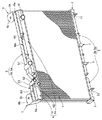
図1はこの実施例の対向流式熱交換器を示す一部切欠正面図、図2は同斜視図、図3は同拡大上面図、図4は同拡大側面図である。
この実施例の対向流式熱交換器は、流入側熱交換器コア1と、流出側熱交換器コア2と、両熱交換器コア1、2間を接続するUターン用中間タンク3と、流入側熱交換器コア1に接続された流入側タンク4と、流出側熱交換器コア2に接続された流出側タンク5と、熱交換器を車体側に支持するブラケット6と、中間タンク3を車体側に支持するゴムブッシュ7と、を備えている。なお、上記ゴムブッシュ7は、本発明の弾性支持部材に相当する。FIG. 1 is a partially cutaway front view showing a counterflow heat exchanger according to this embodiment, FIG. 2 is a perspective view thereof, FIG. 3 is an enlarged top view thereof, and FIG. 4 is an enlarged side view thereof.
The counter-flow heat exchanger of this embodiment includes an inflow side
上記対向流式熱交換器の構造につきさらに詳述すると、流入側熱交換器コア1と流出側熱交換器コア2とは、それぞれ冷却水が流通するチューブ11、21と冷却用のフィン12、22とを交互に横方向に多数連結配置した構造としている。これらの両熱交換器コア1、2はそれらの厚み方向に並設された状態で車体に搭載配置している。 The structure of the counterflow heat exchanger will be described in more detail. The inflow side
両熱交換器コア1、2は、これらの両チューブ11、21の下端側をUターン用中間タンク3にそれぞれ接続するとともに、両チューブ11、21の上端側をそれぞれ別体として形成した流入側タンク4と流出側タンク5とにそれぞれ接続している。 The both
ブラケット6、6は、流入側タンク4と流出側タンク5とをラジエータコアサポート8に取り付けるための金具であり、流入側タンク4と流出側タンク5の長手方向両端部に設けている。なお、ラジエータコアサポート8は、本発明の車体側部材に相当する。 The
即ち、これらの各ブラケット6は、その熱交換器側取付部6aを流入側タンク4と流出側タンク5の長手方向両端面部に対しそれぞれ1本のボルト61、61によりこれらのボルト61、61を中心としてそれぞれ回動可能になるように、取り付けている。また、これらの垂直な熱交換器側取付部6a、6aからそれぞれ内向き略水平方向に折曲形成された車体側取付部6b、6bには、車体側に取り付け固定するためのボルト穴6c、6cをそれぞれ1箇所設けると共に、これらのボルト穴6c、6cの下面側には、ウエルドナット6d、6dを溶接にて予め固定しておき、ラジエータコアサポート8側から挿通したボルト62、62を、ブッシュを介してウエルドナット6dにねじ込むことにより、流入側タンク4と流出側タンク5とをラジエータコアサポート8側に取り付け固定している。 That is, each of these
一方、Uターン用中間タンク3は、この下部に配置した複数のゴムブッシュ7、7を介してラジエータコアサポートに弾性支持している。 On the other hand, the U-turn
流入側タンク4と流出側タンク5とUターン用中間タンク3との各内部は、それらの長手方向の途中で仕切って分割することにより、大容量の第1ラジエータRAと、小容量の第2ラジエータRBとが幅方向に一体化された構造となるようにしている。 The insides of the
第1ラジエータRA側の流入側タンク4aと流出側タンク5aとには、流入パイプ41と流出パイプ51とをそれぞれ接続している。また、第2ラジエータRB側の流入側タンク4bと流出側タンク5bとにも、流入パイプ42と流出パイプ52とをそれぞれ接続している。なお、流入側タンク4a、4bにはエア抜きパイプ43、53を、または中間タンク3a、3bにはドレンパイプ31、32をそれぞれ設けてある。 An
なお、一般の内燃機関車両においては、大容量の第1ラジエータRAがエンジン冷却水を冷却し、小容量の第2ラジエータRBは電気系冷却水を冷却するため等に用いることができ、また、ファンコイルユニット(FCU)を用いる燃料電池車(FCV)に適用される場合は、大容量の第1ラジエータRAがエアコンのヒータ回路やフュエルセルスタック等を冷却し、小容量の第2ラジエータRBは冷却水(LLC)を用いる燃料電池車(FCV)におけるインバータのモータやその回路等を冷却するため等に用いることができる。 In a general internal combustion engine vehicle, the large-capacity first radiator RA can be used to cool engine cooling water, and the small-capacity second radiator RB can be used to cool electric cooling water. When applied to a fuel cell vehicle (FCV) using a fan coil unit (FCU), the large-capacity first radiator RA cools the air conditioner heater circuit, the fuel cell stack, etc., and the small-capacity second radiator RB It can be used to cool an inverter motor or its circuit in a fuel cell vehicle (FCV) using cooling water (LLC).
次に、この実施例の対向流式熱交換器の作用・効果を説明する。
上記のように構成された対向流式熱交換器では、第1ラジエータRAおよび第2ラジエータRBにおいて、流入パイプ41、42からそれぞれ各流入側タンク4a、4b内に流入した加熱冷却水は、それぞれ流入側熱交換器コア1、1のチューブ11、11内を流れる間に冷却された後、Uターン用中間タンク3a、3b内に流入し、この中間タンク3a、3b内からそれぞれ流出側熱交換器コア2、2のチューブ21、21内を流れる間にさらに冷却されて流出側タンク5a、5b内に流入し、流出パイプ51、52からそれぞれ排出される。Next, the operation and effect of the counterflow heat exchanger of this embodiment will be described.
In the counterflow heat exchanger configured as described above, in the first radiator RA and the second radiator RB, the heating and cooling water flowing into the
流入側タンク4a、4bに接続される流入側熱交換器コア1、1側を流れる冷却水と、流出側タンク5a、5bに接続される流出側熱交換器コア2、2側を流れる冷却水とは、これら間の温度差が、第1ラジエータRA側では約40℃と極めて大きく、また、第2ラジエータRB側でも約20℃の温度差があるため、流入側熱交換器コア1、1と流出側熱交換器コア2、2との熱膨張差が大きくなる。しかしながら、本対向流式熱交換器では、流入側タンク4と流出側タンク5とをそれぞれ別体に分離して形成すると共に、流入側タンク4と流出側タンク5とを車体側であるラジエータコアサポート8に取り付けるためのブラケット6、6を、流入側タンク4と流出側タンク5との長手方向両端面に対しそれぞれ1本のボルト61、61により、これらの各ボルト61、61を中心として回動可能になるように、取り付けた構造としている。このため、本対向流式熱交換器では、温度変化によりUターン用中間タンク3を中心として流入側熱交換器コア1と流出側熱交換器コア2とがこれらの長手方向(上下方向)に伸縮し、その際、温度差によって両熱交換器コア1、2間に伸縮長さの差が生じても、流入側タンク4a、4bおよび流出側タンク5a、5bに対しブラケット6、6が両ボルト61、61を中心としてそれぞれ相対回動することで、伸縮長さの差を吸収することができる。 Cooling water flowing through the inflow side
また、Uターン用中間タンク3は、複数のゴムブッシュ7、7を介してラジエータコアサポート8に弾性支持した構成としたため、流入側熱交換器コア1と流出側熱交換器コア2との長手方向伸縮をゴムブッシュ7の弾性により吸収することができる。 In addition, since the U-turn
従って、流入側熱交換器コア1と流出側熱交換器コア2とを流れる冷却水の温度差に基づく熱応力によって各部の歪み、亀裂、破損等が発生することを防止することができるようになるという効果が得られる。 Therefore, it is possible to prevent the occurrence of distortion, cracking, breakage, etc. of each part due to the thermal stress based on the temperature difference of the cooling water flowing through the inflow side
また、流入側タンク4と流出側タンク5がそれぞれ別体に形成されることにより、流入側タンク側4を流れる冷却水の熱が直接、流出側タンク5に伝わり、流出側の冷却水が加熱されるのを防止することができる。従って、本対向流式熱交換器の熱交換効率を高めることができるという効果が得られる。 In addition, since the
以上、本発明を実施例に基づき説明してきたが、本発明は上述の実施例に限られるものではなく、本発明の要旨を逸脱しない範囲の設計変更等があっても、本発明に含まれる。 As described above, the present invention has been described based on the embodiments. However, the present invention is not limited to the above-described embodiments, and design changes and the like within the scope of the present invention are included in the present invention. .
例えば、上記実施例では、ブラケット6、6をそれぞれ1本のボルト61、61によりこれらのボルト61、61を中心としてそれぞれ回動可能に取り付けるようにしたが、図5に示すように、ブラケット6側のボルト挿通孔を長孔8aに形成することにより、ブラケット6に対し流入側タンク4a、4bおよび流出側タンク5a、5bがそれぞれ独立して相対摺動して変位可能となるよう構成してもよい。なお、ボルト61、61とブラケット6、6とは、いずれか一方を流入側タンク4a、4bと流出側タンク5a、5bとに、また他方を車体側に取り付けるようにすればよい。 For example, in the above-described embodiment, the
また、上記実施例では、1つのブラケット6に流入側タンク4と流出側タンク5を取り付けるようにしたが、それぞれ別体のブラケットにより取り付けるようにしてもよい。 Moreover, in the said Example, although the
また、上記実施例では、Uターン用中間タンク3側を弾性支持する弾性支持部材としてゴムブッシュ7を用いたが、これに代えて板ばねやコイルスプリング等を用いることもできる。 Moreover, in the said Example, although the
また、上記実施例では、流入側タンク4と流出側タンク5とUターン用中間タンク3との各内部をその長手方向の途中で仕切って分割することにより、大容量の第1ラジエータRAと、小容量の第2ラジエータRBとが幅方向に一体化された構造のものを例に取ったが、このように分割することなく全体を1つのラジエータとして用いるようにしてもよい。 Moreover, in the said Example, by dividing and dividing each inside of the
本発明の対向流式熱交換器は、一対の熱交換器を並列配置して用いるものであれば、自動車等の熱交換器へ適用することができる。 The counterflow heat exchanger of the present invention can be applied to a heat exchanger such as an automobile as long as a pair of heat exchangers are used in parallel.
Claims (3)
該両熱交換器コアに設けられた各チューブの一方端側がそれぞれ接続されたUターン用中間タンクと、
前記熱交換器コアの一方に設けられたチューブの他端側が接続された流入側タンクと、
前記流入側タンクとは別体として分離形成され、前記熱交換器コアの他方に設けられたチューブの他端側が接続された流出側タンクと、を備え、
前記両熱交換器コアが前記中間タンクを中心としてそれぞれ独立して伸縮可能になるように前記流入側タンクと前記流出側タンクと中間タンクとを車体側部材に取り付ける対交流式熱交換器で、
前記流入側タンクと流出側タンクとを車体側に取り付けるためのブラケットを前記流入側タンクと前記流出側タンクの長手方向両端部に設け、
前記各ブラケットは、その前記熱交換器側取付部を前記流入側タンクと前記流出側タンクの長手方向端面部に対しそれぞれ1本のボルトにより各ボルトを中心としてそれぞれ回動可能となるように取り付けたことを特徴とする対向流式熱交換器。A pair of heat exchanger cores having tubes and fins arranged alternately and alternately arranged in parallel in the thickness direction;
A U-turn intermediate tank to which one end side of each tube provided in both heat exchanger cores is connected;
An inflow side tank to which the other end of the tube provided on one side of the heat exchanger core is connected;
An inflow side tank formed separately from the inflow side tank and connected to the other end of the tube provided on the other side of the heat exchanger core,
The two heat exchanger cores the intermediate tank independently stretchable the inlet side tank so as to become the outlet side tank and Keru Installing the intermediate tank to the vehicle body side member pair AC heat exchanger around the so,
Brackets for attaching the inflow side tank and the outflow side tank to the vehicle body side are provided at both longitudinal ends of the inflow side tank and the outflow side tank,
Each bracket is attached so that the heat exchanger side attachment portion can be rotated around each bolt by one bolt with respect to the longitudinal end surface portions of the inflow side tank and the outflow side tank. A counter-flow heat exchanger characterized by that.
該両熱交換器コアに設けられた各チューブの一方端側がそれぞれ接続されたUターン用中間タンクと、
前記熱交換器コアの一方に設けられたチューブの他端側が接続された流入側タンクと、
前記流入側タンクとは別体として分離形成され、前記熱交換器コアの他方に設けられたチューブの他端側が接続された流出側タンクと、を備え、
前記両熱交換器コアが前記中間タンクを中心としてそれぞれ独立して伸縮可能になるように前記流入側タンクと前記流出側タンクと中間タンクとを車体側部材に取り付ける対交流式熱交換器で、
前記流入側タンクと前記流出側タンクとを車体側に取り付けるためのブラケットを前記流入側タンクと前記流出側タンクの長手方向両端部に設け、
前記各ブラケットの前記熱交換器側取付部側のボルト挿通孔を長孔に形成し、該長孔にボルトを摺動可能に挿入することにより、前記ブラケットに対し前記流入側タンクと前記流出側タンクがそれぞれ独立して相対摺動して変位可能となるように構成したことを特徴とする対向流式熱交換器。 A pair of heat exchanger cores having tubes and fins arranged alternately and alternately arranged in parallel in the thickness direction;
A U-turn intermediate tank to which one end side of each tube provided in both heat exchanger cores is connected;
An inflow side tank to which the other end of the tube provided on one side of the heat exchanger core is connected;
An inflow side tank formed separately from the inflow side tank and connected to the other end side of the tube provided on the other side of the heat exchanger core;
An AC heat exchanger for attaching the inflow side tank, the outflow side tank, and the intermediate tank to a vehicle body side member so that the two heat exchanger cores can be independently expanded and contracted around the intermediate tank,
Brackets for attaching the inflow side tank and the outflow side tank to the vehicle body side are provided at both longitudinal ends of the inflow side tank and the outflow side tank,
A bolt insertion hole on the heat exchanger side mounting portion side of each bracket is formed into a long hole, and a bolt is slidably inserted into the long hole, whereby the inflow side tank and the outflow side are inserted into the bracket. A counter-flow heat exchanger, wherein the tanks are configured to be able to displace by sliding relative to each other independently .
前記中間タンクを弾性支持部材を介して車体側に取り付けたことを特徴とする対向流式熱交換器。 A counterflow heat exchanger, wherein the intermediate tank is attached to the vehicle body side through an elastic support member.
Applications Claiming Priority (3)
| Application Number | Priority Date | Filing Date | Title |
|---|---|---|---|
| JP2003356833 | 2003-10-16 | ||
| JP2003356833 | 2003-10-16 | ||
| PCT/JP2004/015052 WO2005038380A1 (en) | 2003-10-16 | 2004-10-13 | Counterflow heat exchanger |
Publications (2)
| Publication Number | Publication Date |
|---|---|
| JPWO2005038380A1 JPWO2005038380A1 (en) | 2007-11-22 |
| JP4345933B2 true JP4345933B2 (en) | 2009-10-14 |
Family
ID=34463224
Family Applications (1)
| Application Number | Title | Priority Date | Filing Date |
|---|---|---|---|
| JP2005514755A Expired - Fee Related JP4345933B2 (en) | 2003-10-16 | 2004-10-13 | Counterflow heat exchanger |
Country Status (4)
| Country | Link |
|---|---|
| US (1) | US7267159B2 (en) |
| EP (1) | EP1688693A4 (en) |
| JP (1) | JP4345933B2 (en) |
| WO (1) | WO2005038380A1 (en) |
Families Citing this family (11)
| Publication number | Priority date | Publication date | Assignee | Title |
|---|---|---|---|---|
| JP4970022B2 (en) * | 2006-08-02 | 2012-07-04 | カルソニックカンセイ株式会社 | Combined heat exchanger and combined heat exchanger system |
| US20080164015A1 (en) * | 2007-01-04 | 2008-07-10 | Steven James Papapanu | Contra-tapered tank design for cross-counterflow radiator |
| FR2911177B1 (en) * | 2007-01-09 | 2009-04-24 | Muller Et Cie Sa | DEVICE FOR ATTACHING AT LEAST ONE CAST IRON ELEMENT TO A SUPPORT |
| JP4949301B2 (en) * | 2008-03-26 | 2012-06-06 | カルソニックカンセイ株式会社 | Radiator core support |
| US8376073B2 (en) * | 2010-02-26 | 2013-02-19 | Nissan North America, Inc. | Vehicle radiator structure |
| DE112011103814T5 (en) * | 2010-11-19 | 2013-08-22 | Modine Manufacturing Company | Heat exchanger assembly and method |
| WO2012135956A1 (en) * | 2011-04-07 | 2012-10-11 | Dana Canada Corporation | Heat exchanger with resiliently mounted bracket |
| US10767937B2 (en) | 2011-10-19 | 2020-09-08 | Carrier Corporation | Flattened tube finned heat exchanger and fabrication method |
| USD735307S1 (en) * | 2012-12-26 | 2015-07-28 | Pgi International Ltd. | Multiport manifold for evaporator coils |
| DE112015002163T5 (en) | 2014-05-08 | 2017-02-09 | Dana Canada Corporation | Heat exchanger with retractable mounting bracket |
| GB2571767B (en) * | 2018-03-08 | 2022-06-08 | Denso Marston Ltd | Heat exchanger assembly and method for mounting a heat exchanger |
Family Cites Families (21)
| Publication number | Priority date | Publication date | Assignee | Title |
|---|---|---|---|---|
| US3123170A (en) * | 1964-03-03 | Radiator with resilient mounting | ||
| GB707593A (en) | 1950-08-11 | 1954-04-21 | Wilhelm Elze | Improvements in or relating to fluid-coolers |
| JPS6011317B2 (en) * | 1982-07-10 | 1985-03-25 | トヨタ自動車株式会社 | Radiator support device |
| JPS6078619U (en) * | 1983-11-04 | 1985-06-01 | トヨタ自動車株式会社 | Radiator support device |
| JPH0338587U (en) * | 1989-08-23 | 1991-04-15 | ||
| JP3043051B2 (en) | 1990-11-22 | 2000-05-22 | 昭和アルミニウム株式会社 | Heat exchange equipment |
| US5314013A (en) * | 1991-03-15 | 1994-05-24 | Sanden Corporation | Heat exchanger |
| US5355941A (en) * | 1993-09-17 | 1994-10-18 | Ford Motor Company | Sealing apparatus for a heat exchanger manifold |
| US5348081A (en) * | 1993-10-12 | 1994-09-20 | General Motors Corporation | High capacity automotive condenser |
| JP3511411B2 (en) | 1994-12-26 | 2004-03-29 | カルソニックカンセイ株式会社 | Integrated heat exchanger |
| FR2739598B1 (en) * | 1995-10-06 | 1997-12-05 | Valeo Thermique Moteur Sa | DEVICE FOR ATTACHING A HIGH TEMPERATURE HEAT EXCHANGER |
| JPH09273830A (en) * | 1996-04-05 | 1997-10-21 | Showa Alum Corp | Evaporator |
| DE19719251C2 (en) * | 1997-05-07 | 2002-09-26 | Valeo Klimatech Gmbh & Co Kg | Distribution / collection box of an at least double-flow evaporator of a motor vehicle air conditioning system |
| FR2783765B1 (en) * | 1998-09-25 | 2000-12-01 | Valeo Thermique Moteur Sa | DEVICE FOR FIXING EQUIPMENT, ESPECIALLY A HEAT EXCHANGER, ON A STRUCTURAL ELEMENT OF A MOTOR VEHICLE |
| FR2783767B1 (en) * | 1998-09-30 | 2000-12-15 | Valeo Thermique Moteur Sa | DEVICE FOR DIRECT MOUNTING OF EQUIPMENT, IN PARTICULAR A HEAT EXCHANGER, ON A STRUCTURAL ELEMENT OF A MOTOR VEHICLE |
| JP2000146481A (en) * | 1998-11-10 | 2000-05-26 | Zexel Corp | Parallel integral heat exchanger |
| JP2000193393A (en) * | 1998-12-24 | 2000-07-14 | Zexel Corp | Paralelly integrated heat exchanger |
| US6237680B1 (en) * | 1999-04-08 | 2001-05-29 | Ronny L. Davis | Laminar flow radiator for motor vehicle |
| US6536517B2 (en) * | 2000-06-26 | 2003-03-25 | Showa Denko K.K. | Evaporator |
| US6745827B2 (en) * | 2001-09-29 | 2004-06-08 | Halla Climate Control Corporation | Heat exchanger |
| JP4029000B2 (en) * | 2002-01-25 | 2008-01-09 | カルソニックカンセイ株式会社 | Manufacturing method of integrated heat exchanger and integrated heat exchanger |
-
2004
- 2004-10-13 JP JP2005514755A patent/JP4345933B2/en not_active Expired - Fee Related
- 2004-10-13 US US10/575,892 patent/US7267159B2/en not_active Expired - Fee Related
- 2004-10-13 WO PCT/JP2004/015052 patent/WO2005038380A1/en active Application Filing
- 2004-10-13 EP EP04792295A patent/EP1688693A4/en not_active Withdrawn
Also Published As
| Publication number | Publication date |
|---|---|
| JPWO2005038380A1 (en) | 2007-11-22 |
| EP1688693A1 (en) | 2006-08-09 |
| US7267159B2 (en) | 2007-09-11 |
| EP1688693A4 (en) | 2013-03-06 |
| WO2005038380A1 (en) | 2005-04-28 |
| US20070017657A1 (en) | 2007-01-25 |
Similar Documents
| Publication | Publication Date | Title |
|---|---|---|
| EP0855566B1 (en) | Integrated heat exchanger | |
| JP4345933B2 (en) | Counterflow heat exchanger | |
| JP2004299609A (en) | Heat exchanging apparatus for vehicle | |
| KR20170082865A (en) | Heat exchanger of bar plate type | |
| CN113383205B (en) | Heat exchanger | |
| JP5071181B2 (en) | Heat exchanger | |
| JP2016200372A (en) | Heat exchanger | |
| JP4487926B2 (en) | Cooling module | |
| US20100230080A1 (en) | Tank structure of heat exchanger | |
| JP2004340485A (en) | Complex heat exchanger | |
| JP2011185489A (en) | Complex type heat exchanger | |
| JP2006207952A (en) | Heat exchanger | |
| JP2006207943A (en) | Cross-flow type radiator | |
| KR101082474B1 (en) | Heat exchanger | |
| KR100457495B1 (en) | Heater Core for an Air Conditioning System of a Car | |
| JP7439537B2 (en) | Heat exchanger | |
| KR200366719Y1 (en) | Heat exchanger | |
| JP2008087747A (en) | Heat exchanger for vehicle | |
| JP2007303734A (en) | Heat exchanger | |
| KR20060011502A (en) | Heat exchanger having condenser and oil cooler installed therein | |
| JP2009041824A (en) | Heat exchanger | |
| WO2019111574A1 (en) | Radiator | |
| KR101082475B1 (en) | Heat exchanger | |
| JP2004243935A (en) | Heat exchanger for vehicle | |
| JP2006347190A (en) | Radiator core support structure |
Legal Events
| Date | Code | Title | Description |
|---|---|---|---|
| A131 | Notification of reasons for refusal |
Free format text: JAPANESE INTERMEDIATE CODE: A131 Effective date: 20090303 |
|
| A521 | Request for written amendment filed |
Free format text: JAPANESE INTERMEDIATE CODE: A523 Effective date: 20090424 |
|
| TRDD | Decision of grant or rejection written | ||
| A01 | Written decision to grant a patent or to grant a registration (utility model) |
Free format text: JAPANESE INTERMEDIATE CODE: A01 Effective date: 20090707 |
|
| A01 | Written decision to grant a patent or to grant a registration (utility model) |
Free format text: JAPANESE INTERMEDIATE CODE: A01 |
|
| A61 | First payment of annual fees (during grant procedure) |
Free format text: JAPANESE INTERMEDIATE CODE: A61 Effective date: 20090708 |
|
| R150 | Certificate of patent or registration of utility model |
Free format text: JAPANESE INTERMEDIATE CODE: R150 |
|
| FPAY | Renewal fee payment (event date is renewal date of database) |
Free format text: PAYMENT UNTIL: 20120724 Year of fee payment: 3 |
|
| FPAY | Renewal fee payment (event date is renewal date of database) |
Free format text: PAYMENT UNTIL: 20130724 Year of fee payment: 4 |
|
| R250 | Receipt of annual fees |
Free format text: JAPANESE INTERMEDIATE CODE: R250 |
|
| LAPS | Cancellation because of no payment of annual fees |