EP1688610A2 - Fluid flow device for fuel evaporative emission control system - Google Patents
Fluid flow device for fuel evaporative emission control system Download PDFInfo
- Publication number
- EP1688610A2 EP1688610A2 EP06270006A EP06270006A EP1688610A2 EP 1688610 A2 EP1688610 A2 EP 1688610A2 EP 06270006 A EP06270006 A EP 06270006A EP 06270006 A EP06270006 A EP 06270006A EP 1688610 A2 EP1688610 A2 EP 1688610A2
- Authority
- EP
- European Patent Office
- Prior art keywords
- fluid flow
- flow device
- control system
- emission control
- flow
- Prior art date
- Legal status (The legal status is an assumption and is not a legal conclusion. Google has not performed a legal analysis and makes no representation as to the accuracy of the status listed.)
- Withdrawn
Links
- 239000012530 fluid Substances 0.000 title claims abstract description 27
- 239000000446 fuel Substances 0.000 title claims abstract description 16
- 238000010926 purge Methods 0.000 claims abstract description 9
- 230000004075 alteration Effects 0.000 claims description 5
- 238000001179 sorption measurement Methods 0.000 claims description 4
- 239000004743 Polypropylene Substances 0.000 claims description 2
- -1 polypropylene Polymers 0.000 claims description 2
- 229920001155 polypropylene Polymers 0.000 claims description 2
- 239000002991 molded plastic Substances 0.000 claims 1
- OKTJSMMVPCPJKN-UHFFFAOYSA-N Carbon Chemical compound [C] OKTJSMMVPCPJKN-UHFFFAOYSA-N 0.000 abstract description 16
- 239000002828 fuel tank Substances 0.000 abstract description 3
- 239000003570 air Substances 0.000 description 4
- 229910052799 carbon Inorganic materials 0.000 description 4
- 230000008020 evaporation Effects 0.000 description 3
- 238000001704 evaporation Methods 0.000 description 3
- 229930195733 hydrocarbon Natural products 0.000 description 3
- 150000002430 hydrocarbons Chemical class 0.000 description 3
- 239000002245 particle Substances 0.000 description 2
- 239000004215 Carbon black (E152) Substances 0.000 description 1
- 238000003915 air pollution Methods 0.000 description 1
- 239000012080 ambient air Substances 0.000 description 1
- 238000010586 diagram Methods 0.000 description 1
- 239000008187 granular material Substances 0.000 description 1
- 238000009434 installation Methods 0.000 description 1
- 239000000203 mixture Substances 0.000 description 1
- 238000000465 moulding Methods 0.000 description 1
- 239000008188 pellet Substances 0.000 description 1
- 239000004033 plastic Substances 0.000 description 1
- 229920003023 plastic Polymers 0.000 description 1
- 238000013022 venting Methods 0.000 description 1
Images
Classifications
-
- F—MECHANICAL ENGINEERING; LIGHTING; HEATING; WEAPONS; BLASTING
- F02—COMBUSTION ENGINES; HOT-GAS OR COMBUSTION-PRODUCT ENGINE PLANTS
- F02M—SUPPLYING COMBUSTION ENGINES IN GENERAL WITH COMBUSTIBLE MIXTURES OR CONSTITUENTS THEREOF
- F02M25/00—Engine-pertinent apparatus for adding non-fuel substances or small quantities of secondary fuel to combustion-air, main fuel or fuel-air mixture
- F02M25/08—Engine-pertinent apparatus for adding non-fuel substances or small quantities of secondary fuel to combustion-air, main fuel or fuel-air mixture adding fuel vapours drawn from engine fuel reservoir
- F02M25/0854—Details of the absorption canister
Definitions
- This invention relates to a fluid flow device for use in a fuel evaporative emission control system.
- the present invention provides a fluid flow device for use in a fuel evaporative emission control system, the device comprising a fluid flow passage having an inlet and an outlet, and fluid flow alteration means within the fluid flow passage effective to give relatively unobstructed flow in one direction and relatively obstructed flow in the opposite direction, whereby in use flow in said opposite direction aids purging of an adsorption canister.
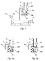
- a vehicle fuel system includes a fuel tank 10 containing fuel 11 and having a fill pipe 12 closed by a cap 14 which forms a seal with the fill pipe 12. Fuel is discharged from the tank 10 via a fuel line 16. The fuel tank is vented to atmosphere by a connection line 18 which leads to a canister 20 containing granules / pellets of activated carbon.
- the canister 20 has a first chamber 20A and second chamber 20B.
- a purge line 4 having a valve 3 is connected to first chamber 20A and a vent line 5 having a fluid flow device 22 is connected to second chamber 20B. As shown in Fig.
- valve 3 when the vehicle engine is inactive the valve 3 is closed and any increase in pressure caused by fuel evaporation is vented to atmosphere along route 1 which passes via canister chambers 20A, 20B (in which fuel vapours are adsorbed onto the activated carbon) and fluid flow device 22.
- valve 3 When the engine is activated, valve 3 is open and ambient air is drawn through the canister chambers 20A and 20B via the fluid flow device 22, and this air flow "purges" the activated carbon by de-adsorbing the fuel there through. The outflow is purged to the engine via line 4.
- the invention improves upon known types by providing the fluid flow device 22 in the line between the canister 20 and the vent.
- the fluid flow device 22 is based on the concept of a device which provides a relatively low resistance to fluid flow during venting, while providing a relatively high resistance during purging so as to give more intimate contact between the purge air and the carbon particles.
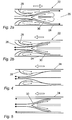
- Figure 2 shows one form of fluid flow device 22. This consists of a housing 24 forming a flow passage 26 which contains, in series, a converger 28 and a diffuser 30.
- Figure 2a When flow is in one direction (Figure 2a), the pressure drop through the device is small and there is little creation of vortexes and low turbulence.
- Figure 2b When flow is in the other direction ( Figure 2b), the pressure drop is much higher, and substantial vortexes and turbulence are present.
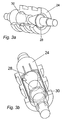
- FIG 3 shows a practical realisation of the scheme of Figure 2, like parts being denoted by like references.
- the housing 24, the converger 28 and the diffuser 30 can each be formed as a plastics moulding, suitably of polypropylene.
- the housing 24 will of course be in two parts before assembly.
- the device shown in Figure 3 is suitable for inclusion as a separate item in a vent line.
- the device of the invention could be integrated with the carbon canister itself to reduce the part count and speed installation.
Landscapes
- Engineering & Computer Science (AREA)
- Chemical & Material Sciences (AREA)
- Combustion & Propulsion (AREA)
- Mechanical Engineering (AREA)
- General Engineering & Computer Science (AREA)
- Supplying Secondary Fuel Or The Like To Fuel, Air Or Fuel-Air Mixtures (AREA)
- Cooling, Air Intake And Gas Exhaust, And Fuel Tank Arrangements In Propulsion Units (AREA)
Abstract

Description
- This invention relates to a fluid flow device for use in a fuel evaporative emission control system.
- In many jurisdictions regulations require the use of systems to prevent or minimise air pollution by evaporation of fuel from vehicle tanks. Commonly, such systems make use of a "carbon canister" arrangement, in which hydrocarbon vapours arising from evaporation of tank fuel are adsorbed on activated carbon particles within a container or canister when the vehicle is inactive. The adsorbed hydrocarbons are subsequently removed or purged during engine operation by drawing air through the canister and directing the resulting air/fuel mixture into the engine intake system.
- The purging of canisters is frequently inefficient, leading to hydrocarbons remaining within the canister. There is a need to improve the efficiency and completeness of such purging.
- It is known to use conical or frusto-conical flow diverters in carbon adsorption canisters: see for example US4,403,587, US4,338,106US4,507,132, and EPO,756,079. However, these prior art arrangements use such elements to distribute incoming fluid within the activated carbon, and the conical/frusto-conical elements are not used for gas dynamic purposes.
- The present invention provides a fluid flow device for use in a fuel evaporative emission control system, the device comprising a fluid flow passage having an inlet and an outlet, and fluid flow alteration means within the fluid flow passage effective to give relatively unobstructed flow in one direction and relatively obstructed flow in the opposite direction, whereby in use flow in said opposite direction aids purging of an adsorption canister.
- Preferred features and advantages of the invention will be apparent from the claims and from the following description.
- Embodiments of the invention will now be described, by way of example only, with reference to the drawings, in which:
- Figure 1 is a schematic diagram of a vehicle fuel system incorporating the invention;
- Figure 2a is a schematic cross-section of one embodiment of device with fluid flow in a first direction;
- Figure 2b shows the device of Fig. 2a with flow in the opposite direction;
- Figures 3a and 3b are perspective views from different directions of one form of practical realisation of the device of Fig. 2; and
- Figures 4 and 5 are schematic cross-sections of alternative forms of device.
- Referring to Figure 1, a vehicle fuel system includes a
fuel tank 10 containingfuel 11 and having afill pipe 12 closed by acap 14 which forms a seal with thefill pipe 12. Fuel is discharged from thetank 10 via afuel line 16. The fuel tank is vented to atmosphere by aconnection line 18 which leads to acanister 20 containing granules / pellets of activated carbon. Thecanister 20 has afirst chamber 20A andsecond chamber 20B. Apurge line 4 having avalve 3 is connected tofirst chamber 20A and avent line 5 having afluid flow device 22 is connected tosecond chamber 20B. As shown in Fig. 1A, when the vehicle engine is inactive thevalve 3 is closed and any increase in pressure caused by fuel evaporation is vented to atmosphere alongroute 1 which passes viacanister chambers fluid flow device 22. When the engine is activated,valve 3 is open and ambient air is drawn through thecanister chambers fluid flow device 22, and this air flow "purges" the activated carbon by de-adsorbing the fuel there through. The outflow is purged to the engine vialine 4. - The invention improves upon known types by providing the
fluid flow device 22 in the line between thecanister 20 and the vent. Thefluid flow device 22 is based on the concept of a device which provides a relatively low resistance to fluid flow during venting, while providing a relatively high resistance during purging so as to give more intimate contact between the purge air and the carbon particles. - Figure 2 shows one form of
fluid flow device 22. This consists of ahousing 24 forming aflow passage 26 which contains, in series, aconverger 28 and adiffuser 30. When flow is in one direction (Figure 2a), the pressure drop through the device is small and there is little creation of vortexes and low turbulence. When flow is in the other direction (Figure 2b), the pressure drop is much higher, and substantial vortexes and turbulence are present. - Figure 3 shows a practical realisation of the scheme of Figure 2, like parts being denoted by like references. The
housing 24, theconverger 28 and thediffuser 30 can each be formed as a plastics moulding, suitably of polypropylene. Thehousing 24 will of course be in two parts before assembly. - It is possible to provide a useful, though less desirable, flow device with only a converger, as in Figure 4, or only a diffuser, as in Figure 5. The required effect could also be produced by flow devices including other forms of interruption or baffle.
- The device shown in Figure 3 is suitable for inclusion as a separate item in a vent line. Alternatively, the device of the invention could be integrated with the carbon canister itself to reduce the part count and speed installation.
Claims (8)
- A fluid flow device for use in a fuel evaporative emission control system, the device comprising a fluid flow passage having an inlet and an outlet, and fluid flow alteration means within the fluid flow passage effective to give relatively unobstructed flow in one direction and relatively obstructed flow in the opposite direction, whereby in use flow in said opposite direction aids purging of an adsorption canister.
- A device according to claim 1, in which the fluid flow alteration means operates by producing dynamic effects within the fluid flow.
- A device according to claim 2, in which the fluid flow alteration means has no moving parts.
- A device according to claim 3, in which the fluid flow alteration means comprises a series combination of a diffuser and a converger.
- A device according to any preceding claim, in the form of a stand-alone device adapted to be connected in a fluid conduit.
- A device according to any of claims 1 to 4, the device forming an integral part of an adsorption canister.
- A device according to any preceding claim, formed of moulded plastics.
- A device according to claim 7, formed of polypropylene.
Applications Claiming Priority (1)
| Application Number | Priority Date | Filing Date | Title |
|---|---|---|---|
| GB0502233A GB0502233D0 (en) | 2005-02-03 | 2005-02-03 | Fuel vapour storage canister |
Publications (2)
| Publication Number | Publication Date |
|---|---|
| EP1688610A2 true EP1688610A2 (en) | 2006-08-09 |
| EP1688610A3 EP1688610A3 (en) | 2009-07-08 |
Family
ID=34307922
Family Applications (1)
| Application Number | Title | Priority Date | Filing Date |
|---|---|---|---|
| EP06270006A Withdrawn EP1688610A3 (en) | 2005-02-03 | 2006-01-18 | Fluid flow device for fuel evaporative emission control system |
Country Status (2)
| Country | Link |
|---|---|
| EP (1) | EP1688610A3 (en) |
| GB (1) | GB0502233D0 (en) |
Cited By (1)
| Publication number | Priority date | Publication date | Assignee | Title |
|---|---|---|---|---|
| US9845745B2 (en) | 2015-07-08 | 2017-12-19 | Ford Global Technologies, Llc | EVAP system with valve to improve canister purging |
Citations (4)
| Publication number | Priority date | Publication date | Assignee | Title |
|---|---|---|---|---|
| US4338106A (en) | 1979-11-09 | 1982-07-06 | Nippon Soken, Inc. | Canister for fuel evaporative emission control system |
| US4403587A (en) | 1981-03-23 | 1983-09-13 | Nippon Soken, Inc. | Fuel evaporative emission control apparatus for vehicles |
| US4507132A (en) | 1983-08-12 | 1985-03-26 | Aisan Industry Co., Ltd. | Fuel evaporation preventing device |
| EP0756079A1 (en) | 1995-07-26 | 1997-01-29 | Toyota Jidosha Kabushiki Kaisha | Canister |
Family Cites Families (4)
| Publication number | Priority date | Publication date | Assignee | Title |
|---|---|---|---|---|
| US4750923A (en) * | 1985-11-08 | 1988-06-14 | Aisan Kogyo Kabushiki Kaisha | Canister for reducing fuel vapor loss |
| DE4140258C1 (en) * | 1991-12-06 | 1993-04-15 | Robert Bosch Gmbh, 7000 Stuttgart, De | |
| JP4047467B2 (en) * | 1998-02-17 | 2008-02-13 | 東洋▲ろ▼機製造株式会社 | Filter device for canister |
| US6668876B2 (en) * | 2001-06-14 | 2003-12-30 | Siemens Vdo Automotive, Incorporated | Method for fuel vapor pressure management |
-
2005
- 2005-02-03 GB GB0502233A patent/GB0502233D0/en not_active Ceased
-
2006
- 2006-01-18 EP EP06270006A patent/EP1688610A3/en not_active Withdrawn
Patent Citations (4)
| Publication number | Priority date | Publication date | Assignee | Title |
|---|---|---|---|---|
| US4338106A (en) | 1979-11-09 | 1982-07-06 | Nippon Soken, Inc. | Canister for fuel evaporative emission control system |
| US4403587A (en) | 1981-03-23 | 1983-09-13 | Nippon Soken, Inc. | Fuel evaporative emission control apparatus for vehicles |
| US4507132A (en) | 1983-08-12 | 1985-03-26 | Aisan Industry Co., Ltd. | Fuel evaporation preventing device |
| EP0756079A1 (en) | 1995-07-26 | 1997-01-29 | Toyota Jidosha Kabushiki Kaisha | Canister |
Cited By (1)
| Publication number | Priority date | Publication date | Assignee | Title |
|---|---|---|---|---|
| US9845745B2 (en) | 2015-07-08 | 2017-12-19 | Ford Global Technologies, Llc | EVAP system with valve to improve canister purging |
Also Published As
| Publication number | Publication date |
|---|---|
| GB0502233D0 (en) | 2005-03-09 |
| EP1688610A3 (en) | 2009-07-08 |
Similar Documents
| Publication | Publication Date | Title |
|---|---|---|
| US5460136A (en) | Evaporative fuel-adsorbing device and evaporative emission control system including same | |
| US7249595B2 (en) | Vapor vent valve with pressure relief function integrated to carbon canister | |
| US5906189A (en) | Evaporative fuel controller for internal combustion engine | |
| US20100126477A1 (en) | Evaporative emissions control system | |
| JPS6040773A (en) | Device for preventing evaporation of fuel | |
| CN107532545A (en) | Evaporated fuel treating apparatus | |
| JP3274084B2 (en) | Canister | |
| US20050098160A1 (en) | Fuel vent assembly with floatless rollover protection | |
| JPH1172054A (en) | Fuel vapor emission preventive device | |
| US20080223343A1 (en) | Fuel vapor control apparatus | |
| US7909024B2 (en) | Hydrocarbon fuel vapour filter system | |
| WO2006067586A3 (en) | Controlling vapor emission in a small engine fuel tank system | |
| US7617851B2 (en) | Refueling vapor recovery system | |
| JP3320722B2 (en) | Exhaust device for fuel tank of internal combustion engine | |
| CN110869656A (en) | valve module | |
| JP2006266267A (en) | Fuel evaporative emission control system for small engine and its method | |
| AU2007282043B2 (en) | Vapor trapping canister vapor pressure management system | |
| EP1688610A2 (en) | Fluid flow device for fuel evaporative emission control system | |
| KR100265313B1 (en) | Air bleeder for a fuel tank of an internal cumbustion engine | |
| US5503659A (en) | Ventguard | |
| JP5193352B2 (en) | Automotive fuel tank | |
| CN114109662A (en) | Fuel system for vehicle | |
| JPH11193755A (en) | Evaporative fuel control system for internal combustion engine | |
| EP2071172A1 (en) | Canister with overmolded filter | |
| WO2016147717A1 (en) | Canister |
Legal Events
| Date | Code | Title | Description |
|---|---|---|---|
| PUAI | Public reference made under article 153(3) epc to a published international application that has entered the european phase |
Free format text: ORIGINAL CODE: 0009012 |
|
| AK | Designated contracting states |
Kind code of ref document: A2 Designated state(s): AT BE BG CH CY CZ DE DK EE ES FI FR GB GR HU IE IS IT LI LT LU LV MC NL PL PT RO SE SI SK TR |
|
| AX | Request for extension of the european patent |
Extension state: AL BA HR MK YU |
|
| PUAL | Search report despatched |
Free format text: ORIGINAL CODE: 0009013 |
|
| AK | Designated contracting states |
Kind code of ref document: A3 Designated state(s): AT BE BG CH CY CZ DE DK EE ES FI FR GB GR HU IE IS IT LI LT LU LV MC NL PL PT RO SE SI SK TR |
|
| AX | Request for extension of the european patent |
Extension state: AL BA HR MK YU |
|
| AKX | Designation fees paid | ||
| REG | Reference to a national code |
Ref country code: DE Ref legal event code: 8566 |
|
| STAA | Information on the status of an ep patent application or granted ep patent |
Free format text: STATUS: THE APPLICATION IS DEEMED TO BE WITHDRAWN |
|
| 18D | Application deemed to be withdrawn |
Effective date: 20100109 |