EP1687862B1 - Battery including aluminum components - Google Patents
Battery including aluminum components Download PDFInfo
- Publication number
- EP1687862B1 EP1687862B1 EP04820016A EP04820016A EP1687862B1 EP 1687862 B1 EP1687862 B1 EP 1687862B1 EP 04820016 A EP04820016 A EP 04820016A EP 04820016 A EP04820016 A EP 04820016A EP 1687862 B1 EP1687862 B1 EP 1687862B1
- Authority
- EP
- European Patent Office
- Prior art keywords
- grid
- aluminum alloy
- weight
- cathode
- aluminum
- Prior art date
- Legal status (The legal status is an assumption and is not a legal conclusion. Google has not performed a legal analysis and makes no representation as to the accuracy of the status listed.)
- Expired - Lifetime
Links
- XAGFODPZIPBFFR-UHFFFAOYSA-N aluminium Chemical compound [Al] XAGFODPZIPBFFR-UHFFFAOYSA-N 0.000 title claims abstract description 40
- 229910052782 aluminium Inorganic materials 0.000 title claims abstract description 39
- WHXSMMKQMYFTQS-UHFFFAOYSA-N Lithium Chemical compound [Li] WHXSMMKQMYFTQS-UHFFFAOYSA-N 0.000 claims abstract description 11
- 229910052744 lithium Inorganic materials 0.000 claims abstract description 11
- 229910000838 Al alloy Inorganic materials 0.000 claims description 41
- 239000000203 mixture Substances 0.000 claims description 23
- OKTJSMMVPCPJKN-UHFFFAOYSA-N Carbon Chemical compound [C] OKTJSMMVPCPJKN-UHFFFAOYSA-N 0.000 claims description 19
- 238000003490 calendering Methods 0.000 claims description 19
- 229910052751 metal Inorganic materials 0.000 claims description 19
- 239000002184 metal Substances 0.000 claims description 19
- 229910052799 carbon Inorganic materials 0.000 claims description 14
- 239000011248 coating agent Substances 0.000 claims description 13
- 238000000576 coating method Methods 0.000 claims description 13
- 239000011230 binding agent Substances 0.000 claims description 12
- 239000006182 cathode active material Substances 0.000 claims description 11
- NUJOXMJBOLGQSY-UHFFFAOYSA-N manganese dioxide Chemical compound O=[Mn]=O NUJOXMJBOLGQSY-UHFFFAOYSA-N 0.000 claims description 10
- XEEYBQQBJWHFJM-UHFFFAOYSA-N Iron Chemical compound [Fe] XEEYBQQBJWHFJM-UHFFFAOYSA-N 0.000 claims description 8
- PXHVJJICTQNCMI-UHFFFAOYSA-N Nickel Chemical compound [Ni] PXHVJJICTQNCMI-UHFFFAOYSA-N 0.000 claims description 8
- 238000001035 drying Methods 0.000 claims description 8
- 239000010936 titanium Substances 0.000 claims description 7
- RTAQQCXQSZGOHL-UHFFFAOYSA-N Titanium Chemical compound [Ti] RTAQQCXQSZGOHL-UHFFFAOYSA-N 0.000 claims description 6
- 238000004519 manufacturing process Methods 0.000 claims description 6
- 239000002002 slurry Substances 0.000 claims description 6
- 229910052719 titanium Inorganic materials 0.000 claims description 6
- FYYHWMGAXLPEAU-UHFFFAOYSA-N Magnesium Chemical compound [Mg] FYYHWMGAXLPEAU-UHFFFAOYSA-N 0.000 claims description 5
- 229910052749 magnesium Inorganic materials 0.000 claims description 5
- 239000011777 magnesium Substances 0.000 claims description 5
- 239000010703 silicon Substances 0.000 claims description 5
- 229910052710 silicon Inorganic materials 0.000 claims description 5
- RYGMFSIKBFXOCR-UHFFFAOYSA-N Copper Chemical compound [Cu] RYGMFSIKBFXOCR-UHFFFAOYSA-N 0.000 claims description 4
- 229910052802 copper Inorganic materials 0.000 claims description 4
- 239000010949 copper Substances 0.000 claims description 4
- 229910002804 graphite Inorganic materials 0.000 claims description 4
- 239000010439 graphite Substances 0.000 claims description 4
- 229910052742 iron Inorganic materials 0.000 claims description 4
- 229910052759 nickel Inorganic materials 0.000 claims description 4
- LSGOVYNHVSXFFJ-UHFFFAOYSA-N vanadate(3-) Chemical compound [O-][V]([O-])([O-])=O LSGOVYNHVSXFFJ-UHFFFAOYSA-N 0.000 claims description 4
- 239000011701 zinc Substances 0.000 claims description 4
- 229910052725 zinc Inorganic materials 0.000 claims description 4
- HCHKCACWOHOZIP-UHFFFAOYSA-N Zinc Chemical compound [Zn] HCHKCACWOHOZIP-UHFFFAOYSA-N 0.000 claims description 3
- NFMAZVUSKIJEIH-UHFFFAOYSA-N bis(sulfanylidene)iron Chemical compound S=[Fe]=S NFMAZVUSKIJEIH-UHFFFAOYSA-N 0.000 claims description 3
- 229910052804 chromium Inorganic materials 0.000 claims description 3
- 239000011651 chromium Substances 0.000 claims description 3
- 229910000339 iron disulfide Inorganic materials 0.000 claims description 3
- 229920000049 Carbon (fiber) Polymers 0.000 claims description 2
- VYZAMTAEIAYCRO-UHFFFAOYSA-N Chromium Chemical compound [Cr] VYZAMTAEIAYCRO-UHFFFAOYSA-N 0.000 claims description 2
- PWHULOQIROXLJO-UHFFFAOYSA-N Manganese Chemical compound [Mn] PWHULOQIROXLJO-UHFFFAOYSA-N 0.000 claims description 2
- 239000004917 carbon fiber Substances 0.000 claims description 2
- 229910052748 manganese Inorganic materials 0.000 claims description 2
- 239000011572 manganese Substances 0.000 claims description 2
- VNWKTOKETHGBQD-UHFFFAOYSA-N methane Chemical compound C VNWKTOKETHGBQD-UHFFFAOYSA-N 0.000 claims description 2
- 229920000620 organic polymer Polymers 0.000 claims description 2
- 238000000034 method Methods 0.000 claims 26
- 239000004411 aluminium Substances 0.000 claims 1
- 239000010406 cathode material Substances 0.000 abstract description 7
- 229910001220 stainless steel Inorganic materials 0.000 description 22
- 239000010935 stainless steel Substances 0.000 description 22
- 239000000463 material Substances 0.000 description 19
- -1 carbon monofluoride Chemical compound 0.000 description 13
- 239000011149 active material Substances 0.000 description 10
- 239000003792 electrolyte Substances 0.000 description 8
- 229910001094 6061 aluminium alloy Inorganic materials 0.000 description 7
- 229910000619 316 stainless steel Inorganic materials 0.000 description 6
- XLYOFNOQVPJJNP-UHFFFAOYSA-N water Substances O XLYOFNOQVPJJNP-UHFFFAOYSA-N 0.000 description 6
- 150000003839 salts Chemical class 0.000 description 5
- 239000002904 solvent Substances 0.000 description 5
- XUIMIQQOPSSXEZ-UHFFFAOYSA-N Silicon Chemical compound [Si] XUIMIQQOPSSXEZ-UHFFFAOYSA-N 0.000 description 4
- 229920001343 polytetrafluoroethylene Polymers 0.000 description 4
- WEVYAHXRMPXWCK-UHFFFAOYSA-N Acetonitrile Chemical compound CC#N WEVYAHXRMPXWCK-UHFFFAOYSA-N 0.000 description 3
- RTZKZFJDLAIYFH-UHFFFAOYSA-N Diethyl ether Chemical compound CCOCC RTZKZFJDLAIYFH-UHFFFAOYSA-N 0.000 description 3
- 239000003513 alkali Substances 0.000 description 3
- 229910052784 alkaline earth metal Inorganic materials 0.000 description 3
- VRAIHTAYLFXSJJ-UHFFFAOYSA-N alumane Chemical compound [AlH3].[AlH3] VRAIHTAYLFXSJJ-UHFFFAOYSA-N 0.000 description 3
- 239000011888 foil Substances 0.000 description 3
- 229920000642 polymer Polymers 0.000 description 3
- 239000004810 polytetrafluoroethylene Substances 0.000 description 3
- DHKHKXVYLBGOIT-UHFFFAOYSA-N 1,1-Diethoxyethane Chemical compound CCOC(C)OCC DHKHKXVYLBGOIT-UHFFFAOYSA-N 0.000 description 2
- YEJRWHAVMIAJKC-UHFFFAOYSA-N 4-Butyrolactone Chemical compound O=C1CCCO1 YEJRWHAVMIAJKC-UHFFFAOYSA-N 0.000 description 2
- 229910001008 7075 aluminium alloy Inorganic materials 0.000 description 2
- LCGLNKUTAGEVQW-UHFFFAOYSA-N Dimethyl ether Chemical compound COC LCGLNKUTAGEVQW-UHFFFAOYSA-N 0.000 description 2
- 229910019142 PO4 Inorganic materials 0.000 description 2
- 239000004952 Polyamide Substances 0.000 description 2
- 239000004743 Polypropylene Substances 0.000 description 2
- NINIDFKCEFEMDL-UHFFFAOYSA-N Sulfur Chemical compound [S] NINIDFKCEFEMDL-UHFFFAOYSA-N 0.000 description 2
- 150000001342 alkaline earth metals Chemical class 0.000 description 2
- 229910045601 alloy Inorganic materials 0.000 description 2
- 239000000956 alloy Substances 0.000 description 2
- 238000000137 annealing Methods 0.000 description 2
- 229910021383 artificial graphite Inorganic materials 0.000 description 2
- 150000004649 carbonic acid derivatives Chemical class 0.000 description 2
- 239000006257 cathode slurry Substances 0.000 description 2
- 238000004140 cleaning Methods 0.000 description 2
- 238000010276 construction Methods 0.000 description 2
- 230000007797 corrosion Effects 0.000 description 2
- 238000005260 corrosion Methods 0.000 description 2
- YSSSPARMOAYJTE-UHFFFAOYSA-N dibenzo-18-crown-6 Chemical compound O1CCOCCOC2=CC=CC=C2OCCOCCOC2=CC=CC=C21 YSSSPARMOAYJTE-UHFFFAOYSA-N 0.000 description 2
- 238000007599 discharging Methods 0.000 description 2
- GNTDGMZSJNCJKK-UHFFFAOYSA-N divanadium pentaoxide Chemical compound O=[V](=O)O[V](=O)=O GNTDGMZSJNCJKK-UHFFFAOYSA-N 0.000 description 2
- 239000008151 electrolyte solution Substances 0.000 description 2
- 150000002148 esters Chemical class 0.000 description 2
- 150000002170 ethers Chemical class 0.000 description 2
- FKRCODPIKNYEAC-UHFFFAOYSA-N ethyl propionate Chemical compound CCOC(=O)CC FKRCODPIKNYEAC-UHFFFAOYSA-N 0.000 description 2
- 150000002500 ions Chemical class 0.000 description 2
- AMXOYNBUYSYVKV-UHFFFAOYSA-M lithium bromide Chemical compound [Li+].[Br-] AMXOYNBUYSYVKV-UHFFFAOYSA-M 0.000 description 2
- HSZCZNFXUDYRKD-UHFFFAOYSA-M lithium iodide Chemical compound [Li+].[I-] HSZCZNFXUDYRKD-UHFFFAOYSA-M 0.000 description 2
- MHCFAGZWMAWTNR-UHFFFAOYSA-M lithium perchlorate Chemical compound [Li+].[O-]Cl(=O)(=O)=O MHCFAGZWMAWTNR-UHFFFAOYSA-M 0.000 description 2
- 229910001486 lithium perchlorate Inorganic materials 0.000 description 2
- 229910003002 lithium salt Inorganic materials 0.000 description 2
- 159000000002 lithium salts Chemical class 0.000 description 2
- 150000002739 metals Chemical class 0.000 description 2
- JKQOBWVOAYFWKG-UHFFFAOYSA-N molybdenum trioxide Chemical compound O=[Mo](=O)=O JKQOBWVOAYFWKG-UHFFFAOYSA-N 0.000 description 2
- 150000002825 nitriles Chemical class 0.000 description 2
- 239000003960 organic solvent Substances 0.000 description 2
- 235000021317 phosphate Nutrition 0.000 description 2
- 150000003013 phosphoric acid derivatives Chemical class 0.000 description 2
- 229920002492 poly(sulfone) Polymers 0.000 description 2
- 229920002647 polyamide Polymers 0.000 description 2
- 229920001155 polypropylene Polymers 0.000 description 2
- 229920002451 polyvinyl alcohol Polymers 0.000 description 2
- 229920000915 polyvinyl chloride Polymers 0.000 description 2
- 239000004800 polyvinyl chloride Substances 0.000 description 2
- 238000004513 sizing Methods 0.000 description 2
- 239000000243 solution Substances 0.000 description 2
- 239000011593 sulfur Substances 0.000 description 2
- 229910052717 sulfur Inorganic materials 0.000 description 2
- FYSNRJHAOHDILO-UHFFFAOYSA-N thionyl chloride Chemical compound ClS(Cl)=O FYSNRJHAOHDILO-UHFFFAOYSA-N 0.000 description 2
- BQCIDUSAKPWEOX-UHFFFAOYSA-N 1,1-Difluoroethene Chemical compound FC(F)=C BQCIDUSAKPWEOX-UHFFFAOYSA-N 0.000 description 1
- 229910001250 2024 aluminium alloy Inorganic materials 0.000 description 1
- XMWRBQBLMFGWIX-UHFFFAOYSA-N C60 fullerene Chemical class C12=C3C(C4=C56)=C7C8=C5C5=C9C%10=C6C6=C4C1=C1C4=C6C6=C%10C%10=C9C9=C%11C5=C8C5=C8C7=C3C3=C7C2=C1C1=C2C4=C6C4=C%10C6=C9C9=C%11C5=C5C8=C3C3=C7C1=C1C2=C4C6=C2C9=C5C3=C12 XMWRBQBLMFGWIX-UHFFFAOYSA-N 0.000 description 1
- OYPRJOBELJOOCE-UHFFFAOYSA-N Calcium Chemical compound [Ca] OYPRJOBELJOOCE-UHFFFAOYSA-N 0.000 description 1
- VEXZGXHMUGYJMC-UHFFFAOYSA-M Chloride anion Chemical compound [Cl-] VEXZGXHMUGYJMC-UHFFFAOYSA-M 0.000 description 1
- 229910021583 Cobalt(III) fluoride Inorganic materials 0.000 description 1
- OIFBSDVPJOWBCH-UHFFFAOYSA-N Diethyl carbonate Chemical compound CCOC(=O)OCC OIFBSDVPJOWBCH-UHFFFAOYSA-N 0.000 description 1
- XTHFKEDIFFGKHM-UHFFFAOYSA-N Dimethoxyethane Chemical compound COCCOC XTHFKEDIFFGKHM-UHFFFAOYSA-N 0.000 description 1
- KMTRUDSVKNLOMY-UHFFFAOYSA-N Ethylene carbonate Chemical compound O=C1OCCO1 KMTRUDSVKNLOMY-UHFFFAOYSA-N 0.000 description 1
- 229920002449 FKM Polymers 0.000 description 1
- DGAQECJNVWCQMB-PUAWFVPOSA-M Ilexoside XXIX Chemical compound C[C@@H]1CC[C@@]2(CC[C@@]3(C(=CC[C@H]4[C@]3(CC[C@@H]5[C@@]4(CC[C@@H](C5(C)C)OS(=O)(=O)[O-])C)C)[C@@H]2[C@]1(C)O)C)C(=O)O[C@H]6[C@@H]([C@H]([C@@H]([C@H](O6)CO)O)O)O.[Na+] DGAQECJNVWCQMB-PUAWFVPOSA-M 0.000 description 1
- JGFBQFKZKSSODQ-UHFFFAOYSA-N Isothiocyanatocyclopropane Chemical compound S=C=NC1CC1 JGFBQFKZKSSODQ-UHFFFAOYSA-N 0.000 description 1
- 229920002633 Kraton (polymer) Polymers 0.000 description 1
- 229910000733 Li alloy Inorganic materials 0.000 description 1
- RJUFJBKOKNCXHH-UHFFFAOYSA-N Methyl propionate Chemical compound CCC(=O)OC RJUFJBKOKNCXHH-UHFFFAOYSA-N 0.000 description 1
- 239000004677 Nylon Substances 0.000 description 1
- 239000002033 PVDF binder Substances 0.000 description 1
- 239000004698 Polyethylene Substances 0.000 description 1
- 239000004372 Polyvinyl alcohol Substances 0.000 description 1
- ZLMJMSJWJFRBEC-UHFFFAOYSA-N Potassium Chemical compound [K] ZLMJMSJWJFRBEC-UHFFFAOYSA-N 0.000 description 1
- 229910000831 Steel Inorganic materials 0.000 description 1
- 239000004809 Teflon Substances 0.000 description 1
- 229920006362 Teflon® Polymers 0.000 description 1
- QCWXUUIWCKQGHC-UHFFFAOYSA-N Zirconium Chemical compound [Zr] QCWXUUIWCKQGHC-UHFFFAOYSA-N 0.000 description 1
- 239000006230 acetylene black Substances 0.000 description 1
- 229910000941 alkaline earth metal alloy Inorganic materials 0.000 description 1
- 239000006183 anode active material Substances 0.000 description 1
- PWLNAUNEAKQYLH-UHFFFAOYSA-N butyric acid octyl ester Natural products CCCCCCCCOC(=O)CCC PWLNAUNEAKQYLH-UHFFFAOYSA-N 0.000 description 1
- 229910052791 calcium Inorganic materials 0.000 description 1
- 239000011575 calcium Substances 0.000 description 1
- 159000000007 calcium salts Chemical class 0.000 description 1
- 239000006229 carbon black Substances 0.000 description 1
- 150000004770 chalcogenides Chemical class 0.000 description 1
- WZJQNLGQTOCWDS-UHFFFAOYSA-K cobalt(iii) fluoride Chemical compound F[Co](F)F WZJQNLGQTOCWDS-UHFFFAOYSA-K 0.000 description 1
- 239000000571 coke Substances 0.000 description 1
- 230000000295 complement effect Effects 0.000 description 1
- 150000001875 compounds Chemical class 0.000 description 1
- 239000002322 conducting polymer Substances 0.000 description 1
- 229920001940 conductive polymer Polymers 0.000 description 1
- 239000004020 conductor Substances 0.000 description 1
- 229920001577 copolymer Polymers 0.000 description 1
- 238000007688 edging Methods 0.000 description 1
- 230000005611 electricity Effects 0.000 description 1
- JBTWLSYIZRCDFO-UHFFFAOYSA-N ethyl methyl carbonate Chemical compound CCOC(=O)OC JBTWLSYIZRCDFO-UHFFFAOYSA-N 0.000 description 1
- 150000004820 halides Chemical class 0.000 description 1
- 238000010438 heat treatment Methods 0.000 description 1
- HCDGVLDPFQMKDK-UHFFFAOYSA-N hexafluoropropylene Chemical group FC(F)=C(F)C(F)(F)F HCDGVLDPFQMKDK-UHFFFAOYSA-N 0.000 description 1
- 238000007654 immersion Methods 0.000 description 1
- 238000003780 insertion Methods 0.000 description 1
- 230000037431 insertion Effects 0.000 description 1
- 239000001989 lithium alloy Substances 0.000 description 1
- 229910001537 lithium tetrachloroaluminate Inorganic materials 0.000 description 1
- 229910001496 lithium tetrafluoroborate Inorganic materials 0.000 description 1
- QSZMZKBZAYQGRS-UHFFFAOYSA-N lithium;bis(trifluoromethylsulfonyl)azanide Chemical compound [Li+].FC(F)(F)S(=O)(=O)[N-]S(=O)(=O)C(F)(F)F QSZMZKBZAYQGRS-UHFFFAOYSA-N 0.000 description 1
- MCVFFRWZNYZUIJ-UHFFFAOYSA-M lithium;trifluoromethanesulfonate Chemical compound [Li+].[O-]S(=O)(=O)C(F)(F)F MCVFFRWZNYZUIJ-UHFFFAOYSA-M 0.000 description 1
- 238000011068 loading method Methods 0.000 description 1
- 159000000003 magnesium salts Chemical class 0.000 description 1
- WPBNNNQJVZRUHP-UHFFFAOYSA-L manganese(2+);methyl n-[[2-(methoxycarbonylcarbamothioylamino)phenyl]carbamothioyl]carbamate;n-[2-(sulfidocarbothioylamino)ethyl]carbamodithioate Chemical compound [Mn+2].[S-]C(=S)NCCNC([S-])=S.COC(=O)NC(=S)NC1=CC=CC=C1NC(=S)NC(=O)OC WPBNNNQJVZRUHP-UHFFFAOYSA-L 0.000 description 1
- 229910001507 metal halide Inorganic materials 0.000 description 1
- 229910044991 metal oxide Inorganic materials 0.000 description 1
- 150000004706 metal oxides Chemical class 0.000 description 1
- QLOAVXSYZAJECW-UHFFFAOYSA-N methane;molecular fluorine Chemical compound C.FF QLOAVXSYZAJECW-UHFFFAOYSA-N 0.000 description 1
- 229940017219 methyl propionate Drugs 0.000 description 1
- 238000002156 mixing Methods 0.000 description 1
- 238000012986 modification Methods 0.000 description 1
- 230000004048 modification Effects 0.000 description 1
- CWQXQMHSOZUFJS-UHFFFAOYSA-N molybdenum disulfide Chemical compound S=[Mo]=S CWQXQMHSOZUFJS-UHFFFAOYSA-N 0.000 description 1
- MPDOUGUGIVBSGZ-UHFFFAOYSA-N n-(cyclobutylmethyl)-3-(trifluoromethyl)aniline Chemical compound FC(F)(F)C1=CC=CC(NCC2CCC2)=C1 MPDOUGUGIVBSGZ-UHFFFAOYSA-N 0.000 description 1
- UUIQMZJEGPQKFD-UHFFFAOYSA-N n-butyric acid methyl ester Natural products CCCC(=O)OC UUIQMZJEGPQKFD-UHFFFAOYSA-N 0.000 description 1
- 229910021382 natural graphite Inorganic materials 0.000 description 1
- 229910021652 non-ferrous alloy Inorganic materials 0.000 description 1
- 239000011255 nonaqueous electrolyte Substances 0.000 description 1
- 229920001778 nylon Polymers 0.000 description 1
- 230000003647 oxidation Effects 0.000 description 1
- 238000007254 oxidation reaction Methods 0.000 description 1
- VLTRZXGMWDSKGL-UHFFFAOYSA-N perchloric acid Chemical class OCl(=O)(=O)=O VLTRZXGMWDSKGL-UHFFFAOYSA-N 0.000 description 1
- 229920003023 plastic Polymers 0.000 description 1
- 239000004033 plastic Substances 0.000 description 1
- 229920000573 polyethylene Polymers 0.000 description 1
- 229920002959 polymer blend Polymers 0.000 description 1
- 229920002981 polyvinylidene fluoride Polymers 0.000 description 1
- 229910052700 potassium Inorganic materials 0.000 description 1
- 239000011591 potassium Substances 0.000 description 1
- XAEFZNCEHLXOMS-UHFFFAOYSA-M potassium benzoate Chemical compound [K+].[O-]C(=O)C1=CC=CC=C1 XAEFZNCEHLXOMS-UHFFFAOYSA-M 0.000 description 1
- 238000003825 pressing Methods 0.000 description 1
- RUOJZAUFBMNUDX-UHFFFAOYSA-N propylene carbonate Chemical compound CC1COC(=O)O1 RUOJZAUFBMNUDX-UHFFFAOYSA-N 0.000 description 1
- 230000003134 recirculating effect Effects 0.000 description 1
- 238000006722 reduction reaction Methods 0.000 description 1
- 239000004065 semiconductor Substances 0.000 description 1
- 239000011734 sodium Substances 0.000 description 1
- 229910052708 sodium Inorganic materials 0.000 description 1
- 159000000000 sodium salts Chemical class 0.000 description 1
- 239000010959 steel Substances 0.000 description 1
- 238000005482 strain hardening Methods 0.000 description 1
- 239000000725 suspension Substances 0.000 description 1
- TXEYQDLBPFQVAA-UHFFFAOYSA-N tetrafluoromethane Chemical compound FC(F)(F)F TXEYQDLBPFQVAA-UHFFFAOYSA-N 0.000 description 1
- DQWPFSLDHJDLRL-UHFFFAOYSA-N triethyl phosphate Chemical compound CCOP(=O)(OCC)OCC DQWPFSLDHJDLRL-UHFFFAOYSA-N 0.000 description 1
- WVLBCYQITXONBZ-UHFFFAOYSA-N trimethyl phosphate Chemical compound COP(=O)(OC)OC WVLBCYQITXONBZ-UHFFFAOYSA-N 0.000 description 1
- 229910052720 vanadium Inorganic materials 0.000 description 1
- LEONUFNNVUYDNQ-UHFFFAOYSA-N vanadium atom Chemical compound [V] LEONUFNNVUYDNQ-UHFFFAOYSA-N 0.000 description 1
- 229910052726 zirconium Inorganic materials 0.000 description 1
Images



Classifications
-
- H—ELECTRICITY
- H01—ELECTRIC ELEMENTS
- H01M—PROCESSES OR MEANS, e.g. BATTERIES, FOR THE DIRECT CONVERSION OF CHEMICAL ENERGY INTO ELECTRICAL ENERGY
- H01M4/00—Electrodes
- H01M4/02—Electrodes composed of, or comprising, active material
- H01M4/36—Selection of substances as active materials, active masses, active liquids
- H01M4/48—Selection of substances as active materials, active masses, active liquids of inorganic oxides or hydroxides
- H01M4/50—Selection of substances as active materials, active masses, active liquids of inorganic oxides or hydroxides of manganese
- H01M4/505—Selection of substances as active materials, active masses, active liquids of inorganic oxides or hydroxides of manganese of mixed oxides or hydroxides containing manganese for inserting or intercalating light metals, e.g. LiMn2O4 or LiMn2OxFy
-
- H—ELECTRICITY
- H01—ELECTRIC ELEMENTS
- H01M—PROCESSES OR MEANS, e.g. BATTERIES, FOR THE DIRECT CONVERSION OF CHEMICAL ENERGY INTO ELECTRICAL ENERGY
- H01M4/00—Electrodes
- H01M4/02—Electrodes composed of, or comprising, active material
- H01M4/13—Electrodes for accumulators with non-aqueous electrolyte, e.g. for lithium-accumulators; Processes of manufacture thereof
-
- H—ELECTRICITY
- H01—ELECTRIC ELEMENTS
- H01M—PROCESSES OR MEANS, e.g. BATTERIES, FOR THE DIRECT CONVERSION OF CHEMICAL ENERGY INTO ELECTRICAL ENERGY
- H01M4/00—Electrodes
- H01M4/02—Electrodes composed of, or comprising, active material
- H01M4/13—Electrodes for accumulators with non-aqueous electrolyte, e.g. for lithium-accumulators; Processes of manufacture thereof
- H01M4/139—Processes of manufacture
-
- H—ELECTRICITY
- H01—ELECTRIC ELEMENTS
- H01M—PROCESSES OR MEANS, e.g. BATTERIES, FOR THE DIRECT CONVERSION OF CHEMICAL ENERGY INTO ELECTRICAL ENERGY
- H01M4/00—Electrodes
- H01M4/02—Electrodes composed of, or comprising, active material
- H01M4/14—Electrodes for lead-acid accumulators
- H01M4/16—Processes of manufacture
-
- H—ELECTRICITY
- H01—ELECTRIC ELEMENTS
- H01M—PROCESSES OR MEANS, e.g. BATTERIES, FOR THE DIRECT CONVERSION OF CHEMICAL ENERGY INTO ELECTRICAL ENERGY
- H01M4/00—Electrodes
- H01M4/02—Electrodes composed of, or comprising, active material
- H01M4/64—Carriers or collectors
- H01M4/70—Carriers or collectors characterised by shape or form
- H01M4/72—Grids
-
- H—ELECTRICITY
- H01—ELECTRIC ELEMENTS
- H01M—PROCESSES OR MEANS, e.g. BATTERIES, FOR THE DIRECT CONVERSION OF CHEMICAL ENERGY INTO ELECTRICAL ENERGY
- H01M4/00—Electrodes
- H01M4/02—Electrodes composed of, or comprising, active material
- H01M4/04—Processes of manufacture in general
- H01M4/043—Processes of manufacture in general involving compressing or compaction
- H01M4/0435—Rolling or calendering
-
- H—ELECTRICITY
- H01—ELECTRIC ELEMENTS
- H01M—PROCESSES OR MEANS, e.g. BATTERIES, FOR THE DIRECT CONVERSION OF CHEMICAL ENERGY INTO ELECTRICAL ENERGY
- H01M4/00—Electrodes
- H01M4/02—Electrodes composed of, or comprising, active material
- H01M4/64—Carriers or collectors
- H01M4/66—Selection of materials
- H01M4/661—Metal or alloys, e.g. alloy coatings
-
- Y—GENERAL TAGGING OF NEW TECHNOLOGICAL DEVELOPMENTS; GENERAL TAGGING OF CROSS-SECTIONAL TECHNOLOGIES SPANNING OVER SEVERAL SECTIONS OF THE IPC; TECHNICAL SUBJECTS COVERED BY FORMER USPC CROSS-REFERENCE ART COLLECTIONS [XRACs] AND DIGESTS
- Y02—TECHNOLOGIES OR APPLICATIONS FOR MITIGATION OR ADAPTATION AGAINST CLIMATE CHANGE
- Y02E—REDUCTION OF GREENHOUSE GAS [GHG] EMISSIONS, RELATED TO ENERGY GENERATION, TRANSMISSION OR DISTRIBUTION
- Y02E60/00—Enabling technologies; Technologies with a potential or indirect contribution to GHG emissions mitigation
- Y02E60/10—Energy storage using batteries
-
- Y—GENERAL TAGGING OF NEW TECHNOLOGICAL DEVELOPMENTS; GENERAL TAGGING OF CROSS-SECTIONAL TECHNOLOGIES SPANNING OVER SEVERAL SECTIONS OF THE IPC; TECHNICAL SUBJECTS COVERED BY FORMER USPC CROSS-REFERENCE ART COLLECTIONS [XRACs] AND DIGESTS
- Y02—TECHNOLOGIES OR APPLICATIONS FOR MITIGATION OR ADAPTATION AGAINST CLIMATE CHANGE
- Y02P—CLIMATE CHANGE MITIGATION TECHNOLOGIES IN THE PRODUCTION OR PROCESSING OF GOODS
- Y02P70/00—Climate change mitigation technologies in the production process for final industrial or consumer products
- Y02P70/50—Manufacturing or production processes characterised by the final manufactured product
Definitions
- This invention relates to batteries including aluminum components.
- a battery contains a negative electrode, typically called the anode, and a positive electrode, typically called the cathode.
- the anode contains an active material that can be oxidized; the cathode contains or consumes an active material that can be reduced.
- the anode active material is capable of reducing the cathode active material.
- anode and the cathode When a battery is used as an electrical energy source in a device, electrical contact is made to the anode and the cathode, allowing electrons to flow through the device and permitting the respective oxidation and reduction reactions to occur to provide electrical power.
- An electrolyte in contact with the anode and the cathode contains ions that flow through the separator between the electrodes to maintain charge balance throughout the battery during discharge.
- a primary lithium battery in general, includes a positive lead which can include aluminum.
- the positive lead is in electrical contact with the cathode of the battery.
- the cathode includes a current collector which can include aluminum.
- U.S. 5,595,837 discloses a method of making a primary lithium battery comprising coating a current collector including an aluminum mesh with a composition including a cathode active material, whilst WO 01/39296 discloses a laminated multi-layer electrochemical cell device.
- a method of making a cathode for a primary lithium battery includes coating an expanded metal grid including aluminum with a composition including a cathode active material.
- a method of making a cathode for a battery includes coating an expanded metal grid including an aluminum alloy with a composition including a cathode active material, wherein the cathode active material includes a manganese dioxide and the composition includes a carbon source and a binder, drying the grid after coating, calendaring the grid to a thickness of less than 20 mils (0.508 mm) after drying, sizing the grid after calendering, edge-cleaning the grid after sizing, heat treating the grid after edge-cleaning, and drying the grid under vacuum after heat treating the grid.
- the composition can be a slurry.
- the cathode active material can include a manganese dioxide, a carbon fluoride such as carbon monofluoride, polycarbon monofluoride, graphite fluoride or CF x , iron disulfide, or a vanadate.
- the composition can include a carbon source.
- the carbon source can include a carbon fiber, a graphite, an acetylenic carbon, or a combination thereof.
- the composition can include a binder.
- the binder can include an organic polymer.
- the binder can include poly(tetrafluoroethylene), poly(vinylalcohol), or a combination thereof.
- the grid can include a 1000 series aluminum, a 2000 series aluminum alloy, a 3000 series aluminum alloy, a 5000 series aluminum alloy, a 6000 series aluminum alloy, or a 7000 series aluminum alloy.
- the grid can include an aluminum alloy including 0-0.4% by weight of chromium, 0.01-6.8% by weight of copper, 0.05-1.3% by weight of iron, 0.1-7% by weight of magnesium, 0-2% by weight of manganese, 0-2% by weight of silicon, less than 0.25% by weight of titanium, 0-2.3% by weight of nickel, and 0-8.2% by weight of zinc.
- the grid can have a resistivity of less than 100 m ⁇ /cm, or of less than 10 m ⁇ /cm.
- the grid can be pulled before coating.
- the grid can be leveled before coating.
- the grid can be dried after coating.
- the grid can be calendered after drying. Calendering can include passing the grid through a gap.
- the gap can have a thickness of less than 25 mils (0.635 mm).
- the grid can be heat treated after calendering.
- the grid can be dried under vacuum after heat treating.
- Primary lithium batteries including a positive lead that includes aluminum can have a lower impedance than batteries having a positive lead of a different material, for example stainless steel.
- the combination of a cathode current collector including aluminum and a positive lead including aluminum can provide greater corrosion stability and conductivity in a battery than the combination of a current collector including aluminum and a positive lead of stainless steel.
- Aluminum or an aluminum alloy can be less expensive than stainless steel.
- a primary lithium electrochemical cell 10 includes an anode 12 in electrical contact with a negative lead 14, a cathode 16 in electrical contact with a crown 18, a separator 20 and an electrolyte.
- Anode 12, cathode 16, separator 20 and the electrolyte are contained within housing 22.
- the electrolyte can be a solution that includes a solvent system and a salt that is at least partially dissolved in the solvent system.
- One end of housing 22 is closed with a positive external contact 24 and an annular insulating gasket 26 that can provide a gas-tight and fluid-tight seal.
- Crown 18 and positive lead 28 connect cathode 16 to positive external contact 24.
- a safety valve is disposed in the inner side of positive external contact 24 and is configured to decrease the pressure within battery 10 when the pressure exceeds some predetermined value.
- the positive lead can be circular or annular and be arranged coaxially with the cylinder, and include radial extensions in the direction of the cathode.
- Electrochemical cell 10 can be, for example, a cylindrical wound cell, a button or coin cell, a prismatic cell, a rigid laminar cell or a flexible pouch, envelope or bag cell.
- Anode 12 can include alkali and alkaline earth metals, such as lithium, sodium, potassium, calcium, magnesium, or alloys thereof.
- the anode can include alloys of alkali or alkaline earth metals with another metal or other metals, for example, aluminum.
- An anode including lithium can include elemental lithium or lithium alloys, or combinations thereof.
- the electrolyte can be a nonaqueous electrolyte solution including a solvent and a salt.
- the salt can be an alkali or alkaline earth salt such as a lithium salt, a sodium salt, a potassium salt, a calcium salt, a magnesium salt, or combinations thereof.
- lithium salts include lithium hexafluorophosphate, lithium tetrafluoroborate, lithium hexafluoroarsenate, lithium perchlorate, lithium iodide, lithium bromide, lithium tetrachloroaluminate, lithium trifluoromethanesulfonate, LiN(CF 3 SO 2 ) 2 , and LiB(C 6 H 4 O 2 ) 2 .
- a perchlorate salt such as lithium perchlorate can be included in the electrolyte to help suppress corrosion of aluminum or an aluminum alloy in the cell, for example in the current collector.
- the concentration of the salt in the electrolyte solution can range from 0.01 molar to 3 molar, from 0.5 molar to 1.5 molar, and in certain embodiments can be 1 molar.
- the solvent can be an organic solvent.
- organic solvents include carbonates, ethers, esters, nitriles and phosphates.
- carbonates include ethylene carbonate, propylene carbonate, diethyl carbonate and ethylmethyl carbonate.
- ethers include diethyl ether, dimethyl ether, dimethoxyethane and diethoxyethane.
- esters include methyl propionate, ethyl propionate, methyl butyrate and gamma-butyrolactone.
- nitriles include acetonitrile.
- phosphates include triethylphosphate and trimethylphosphate.
- the electrolyte can be a polymeric electrolyte.
- Separator 20 can be formed of any separator material used in lithium primary or secondary battery separators.
- separator 20 can be formed of polypropylene, polyethylene, polytetrafluoroethylene, a polyamide (e.g., a nylon), a polysulfone, a polyvinyl chloride, or combinations thereof.
- Separator 20 can have a thickness of from about 12 microns to about 75 microns and more preferably from 12 to about 37 microns. Separator 20 can be cut into pieces of a similar size as anode 12 and cathode 16 and placed therebetween as shown in FIG. 1 .
- the anode, separator, and cathode can be rolled together, especially for use in cylindrical cells.
- housing 22 can be made of a metal such as nickel or nickel plated steel, stainless steel, aluminum-clad stainless steel, aluminum, or an aluminum alloy or a plastic such as polyvinyl chloride, polypropylene, a polysulfone, ABS or a polyamide.
- Housing 22 containing anode 12, cathode 16 and separator 20 can be filled with the electrolytic solution and subsequently hermetically sealed with positive external contact 24 and annular insulating gasket 26.
- Cathode 16 includes a composition that includes cathode active material that can undergo alkali ion insertion during discharge of battery 10.
- the active material can be, e.g., a metal oxide, halide, or chalcogenide; alternatively, the active material can be sulfur, an organosulfur polymer, or a conducting polymer.
- Specific examples include manganese dioxide, cobalt trifluoride, molybdenum sulfide, iron disulfide, thionyl chloride, molybdenum trioxide, sulfur, (C 6 H 5 N) n , and (S 3 N 2 ) n , where n is at least 2.
- the active material can be a vanadate material, such as a vanadium pentoxide. Vanadate materials are described, for example, in U.S. Patent Nos. 6,322,928 and 5,567,548 , each of which is incorporated by reference in its entirety.
- the active material can also be a carbon monofluoride, such as a compound having the formula CF x , where x is 0.5 to 1.0.
- the cathode composition can also include a binder, for example, a polymeric binder such as PTFE, PVDF, Kraton or Viton (e.g., a copolymer of vinylidene difluoride and hexafluoropropylene).
- the cathode composition can also include a carbon source, such as, for example, carbon black, synthetic graphite including expanded graphite or non-synthetic graphite including natural graphite, an acetylenic mesophase carbon, coke, graphitized carbon nanofibers or a polyacetylenic semiconductor.
- a carbon source such as, for example, carbon black, synthetic graphite including expanded graphite or non-synthetic graphite including natural graphite, an acetylenic mesophase carbon, coke, graphitized carbon nanofibers or a polyacetylenic semiconductor.
- the cathode includes a current collector on which the cathode active material can be coated or otherwise deposited.
- the current collector can have a region in contact with positive lead 28 and a second region in contact with the active material.
- the current collector serves to conduct electricity between the positive lead 28 and the active material.
- the current collector can be made of a material that is strong and is a good electrical conductor (i.e. has a low resistivity), for example a metal such as stainless steel, titanium, aluminum or an aluminum alloy. More specifically, the current collector advantageously is composed of a material having a high yield strength, e.g. greater than 50 MPa, a high tensile strength, e.g. greater than 100 MPa, and a low resistivity, e.g. less than 10 -4 ⁇ cm or less than 10 -5 ⁇ cm.
- the aluminum or aluminum alloy current collector can cost less and have a lower resistivity than one of either stainless steel or titanium.
- Aluminum and aluminum alloys are generally grouped into series according to the other elements present in the material. For example, a 1000 series aluminum is almost pure aluminum, a 2000 series aluminum alloy contains primarily aluminum and copper, a 6000 series aluminum alloy contains primarily aluminum, magnesium and silicon, and a 7000 series aluminum alloy contains primarily aluminum and zinc.
- a 1000 series, 2000 series, 3000 series, 5000 series, 6000 series, or 7000 series aluminum alloy can be suitable in a current collector or a positive lead.
- the aluminum alloy can be a 2024, 6061, or a 7075 aluminum alloy.
- Table 1 Compositions of other aluminum alloys can be found in, for example, Metals Handbook, Vol.
- the current collector can take is an expanded metal screen or grid, such as a non-woven expanded metal foil.
- Grids of stainless steel, aluminum or aluminum alloy are available from Dexmet Corporation (Branford, CT).
- a grid composed of aluminum or an aluminum alloy can be lighter and less expensive, have a lower electrical resistance, and have similar strength compared to a grid composed of stainless steel.
- a grid In order to be processed for ultimate use in a battery, it can be important for a grid to have a high yield strength, such as, for a one inch wide sample, greater than 2.5 lbF/ in (437,5N/m) or greater than 5 lbF/ in (875N/m), and a high tensile strength, such as, for a one inch (25.4mm) wide sample, greater than 5 lbF/ in (875N/m) or greater than 7 lbF/ in (1225N/m), to withstand forces applied to it during cathode manufacture.
- a high yield strength such as, for a one inch wide sample, greater than 2.5 lbF/ in (437,5N/m) or greater than 5 lbF/ in (875N/m)
- a high tensile strength such as, for a one inch (25.4mm) wide sample, greater than 5 lbF/ in (875N/m) or greater than 7 lbF/ in (1225N/m
- Yield strength is the maximum pulling force that can be applied to the current collector before it deforms to a certain degree, for example, a 1.14 inch (29 mm) increase in length for a sample initially 22 inches (559 mm) long.
- Tensile strength is the maximum pulling force that can be applied to the current collector before it breaks.
- the mechanical and electrical properties of a grid can be influenced by the composition of the grid, the material thickness, strand width, and the grid long dimension (LWD) and short dimension (SWD).
- the LWD and the SWD of the grid can reflect the machine direction of the grid.
- FIG. 2 depicts a grid and the various dimensions of the grid.
- the conductivity of the grid in the LWD differs from the conductivity of the grid in the SWD.
- treatment of the grid such as annealing, leveling or pulling can influence its mechanical properties. Annealing, or heat-treatment, can change the hardness or temper of the material.
- Leveling by passing the grid between rollers can reduce the thickness of the grid, flatten it, and increase its temper by strain hardening. In certain circumstances, a T3, H36 or H38 temper can be desirable.
- Pulling a grid involves applying a force to alter the grid dimensions, for instance by increasing the SWD. Altering the grid dimensions can alter the current path through the grid, and therefore alter the resistivity in the machine direction and/or the cross direction. Pulling a grid can decrease plasticity and increase tensile strength of the material. The more the grid has been pulled, the less flexible and more brittle it can become.
- a cathode is made by coating a cathode material onto a current collector, drying and then calendering the coated current collector.
- the cathode material is prepared by mixing an active material together with other components such as a binder, solvent/water, and a carbon source.
- the current collector can include a metal such as titanium, stainless steel, aluminum, or an aluminum alloy.
- the current collector can be an expanded metal grid.
- an active material such as manganese dioxide can be combined with carbon, such as graphite and/or acetylene black, and mixed with small amount of water to form a mull mix.
- the total carbon in the mull mix can be between 1% and 10%, for example between 5% and 7.5%.
- the amount of water in the mull mix can be less than 5%, such as between 1% and 3%.
- a binder which can be a water/polymer mixture such as a water/polyvinyl alcohol solution, can be mixed with the mull mix.
- the binder can include less than 10% by weight of the polymer, for example between 5% and 7.5%.
- the mull mix and binder are further blended with a polymer suspension, for example polytetrafluoroethylene (e.g. Teflon 30) in water, to form a cathode slurry.
- the current collector is then coated with the cathode slurry by immersion the current collector in a tank holding the slurry.
- the slurry can be mixed prior to coating. After passing through the tank, excess slurry can be removed by passing the current collector between blades held at a fixed gap that is determined by the desired thickness of slurry on the current collector.
- the coated current collector is dried by passing it through a heated oven. Once dried, the coated current collector can be calendered by passing between rolls to press it to a desired thickness.
- the final thickness after calendering can be in the range of 10 to 30 mils (0.254 to 0.762 mm), such as between 12 and 20 mils (0.305 to 0.508 mm).
- Calendering can increase the strength of a grid and elongate it by 5-40%. It can be important for the current collector to have a high yield strength to withstand calendering.
- the porosity of the cathode can be controlled by adjusting the final thickness of the calendered cathode. After calendering, the coated current collector can be cut to a desired size. One edge of the sized cathode can be cleared of cathode material to form a region for the current collector to contact the positive lead. After edging, the cathode can be heat treated for varying periods of time in the range of 30 to 180 minutes under recirculating air at temperatures between 100 and 250°C. The total time can be less than 10 hours. The cathode can be further dried under vacuum at temperatures between 100 and 250°C prior to being transferred to a dry room for cell assembly. The amount of cathode material on the finished current collector can be in the range of 80-140 mg/cm 2 .
- the anode and cathode are spirally wound together with a portion of the cathode current collector extending axially from one end of the roll.
- the portion of the current collector that extends from the roll can be free of cathode active material.
- the exposed end of the current collector can be welded to a metal tab, which is in electric contact with an external battery contact.
- the grid can be rolled in the machine direction, the pulled direction, perpendicular to the machine direction, or perpendicular to the pulled direction.
- the tab can be welded to the grid to minimize the conductivity of grid and tab assembly.
- the exposed end of the current collector can be in mechanical contact (i.e.
- a cell having a mechanical contact can require fewer parts and steps to manufacture than a cell with a welded contact.
- the mechanical contact can be more effective when the exposed grid is bent towards the center of the roll to create a dome or crown, with the highest point of the crown over the axis of the roll, corresponding to the center of a cylindrical cell.
- the grid can have a denser arrangement of strands than in the non-shaped form.
- a crown can be orderly folded and the dimensions of a crown can be precisely controlled.
- the positive lead 28 can include stainless steel, aluminum, or an aluminum alloy.
- a positive lead composed of aluminum or an aluminum alloy can be lighter and less expensive, and have a lower electrical resistance than a positive lead composed of stainless steel.
- the positive lead can be annular in shape, and can be arranged coaxially with the cylinder.
- the positive lead can also include radial extensions in the direction of the cathode that can engage the current collector.
- An extension can be round (e.g. circular or oval), rectangular, triangular or another shape.
- the positive lead can include extensions having different shapes.
- the positive lead and the current collector are in electrical contact. It can be preferable for both the current collector and the positive lead to include aluminum. Electrical contact between the positive lead and the current collector can be achieved by mechanical contact.
- the positive lead and current collector can be welded together. It can be important for a mechanical contact to be robust, in other words, for the parts to remain in mechanical (and therefore also electrical) contact when subjected to a sudden impact, such as when the battery is dropped onto a hard surface.
- a positive lead can have extensions projecting from a flat surface of the positive lead in the direction of the cathode that can mechanically engage the current collector, for example, a crown.
- the battery can be more robust when the positive lead includes one or more extensions, that is, the battery is less susceptible to damage when dropped on a hard surface.
- the extensions can be formed by pressing a tool having complementary shape into a flat blank.
- a positive lead can have one or more extensions, such as four, six or more extensions.
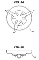
- FIGS. 3A and 3B depict a positive lead 28 with six extensions 30.
- FIG. 3A shows a bottom view (i.e. a view of the surface that contacts a current collector) and
- FIG. 3B shows a side view of a positive
- the positive lead and the cathode current collector are in electrical contact.
- the electrical contact can be the result of mechanical contact between the positive lead and current collector.
- the mechanical contact can be a stainless steel-stainless steel contact, an aluminum-stainless steel contact, or an aluminum-aluminum contact.
- the electrical resistance across an aluminum-aluminum contact can be lower than across a stainless steel-stainless steel contact or an aluminum-stainless steel contact.
- An aluminum-aluminum contact can be more robust than an aluminum-stainless steel contact in a battery, as measured, for example, by ability of the battery to withstand a user drop test. See Examples 3 and 4 below.
- the grids were made from 1145 aluminum (A1 1145), 6061 aluminum alloy (A1 6061), or 316L stainless steel (SS 316L).
- a grid of 6061 aluminum alloy can have a higher yield strength and tensile strength than one of 1145 aluminum alloy, as demonstrated from the results in Table 2.
- Cathodes with current collectors including 6061 aluminum alloy grids were prepared and assembled in tabbed (i.e. the current collector is connected to the external contact by a welded tab) cells.
- the cathodes had the properties listed in Table 3.
- the impedance was measured at ambient conditions using an impedance meter set to a frequency of 1000 Hz and capable of measuring voltage to an accuracy of ⁇ 1%. Closed circuit voltage was measured immediately after discharging the cell at a constant current of 3A for 0.5 seconds.
- the contact resistance of a 12 cm strip of 6061 aluminum alloy under a 500 g weight was measured for three different metal-metal contacts.
- the contact resistance between two samples of 6061 aluminum alloy was 29 ⁇ 5 milliOhms, an order of magnitude lower than contacts between two pieces of stainless steel, 265 ⁇ 28 milliOhms, or between a stainless steel and a 6061 aluminum alloy, 372 ⁇ 64 milliOhms.
- a series of 2/3A cells were built with various combinations of current collector and positive lead materials.
- the current collectors were A1 6061 (pulled or unpulled), or 316 stainless steel (SS 316).
- the positive lead was A1 1145. See Table 4.
- HEC high end camera
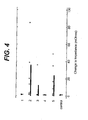
- FIG. 4 The measured changes in impedance for the different types of cells after a drop test are shown in FIG. 4 .
- Closed circuit voltage was measured immediately after discharging the cell at a constant current of 3 A for 0.5 seconds.
- the closed circuit voltages of the different types of cells before and after a drop test are shown in Table 4.
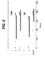
- An HEC test simulates discharge conditions in a high end camera. Cells are repeatedly discharged at a current of 1.8 A for 3 seconds followed by a 7 second rest period. The voltage is recorded at the end of the discharge period. The discharge-rest cycle is repeated until the cell reaches a predetermined cutoff voltage. The number of pulses before cutoff voltages of 2.2 V and 2.0 V were reached are shown in FIGS. 5 and 6 , respectively. The results are summarized in Table 4. In FIGS.
- a series of 2/3A cells were built with various combinations of current collector and positive lead materials and subjected to a drop test, as described above.
- the current collectors were either Al 6061 or stainless steel 316L.
- the positive lead was Al 3003, Al 5052 H36, or stainless steel 316L.
- the closed circuit voltage of the cells was measured before and after the drop test. See Table 5. TABLE 5 Grid material Positive lead material CV, fresh (V) CCV change after drop (V) Al 6061 Al 3003 2.420 0.073 Al 6061 Al 5052 H36 2.430 0.042 SS316 SS316 2.493 0.200
Landscapes
- Chemical & Material Sciences (AREA)
- Chemical Kinetics & Catalysis (AREA)
- Electrochemistry (AREA)
- General Chemical & Material Sciences (AREA)
- Engineering & Computer Science (AREA)
- Materials Engineering (AREA)
- Manufacturing & Machinery (AREA)
- Inorganic Chemistry (AREA)
- Cell Electrode Carriers And Collectors (AREA)
- Secondary Cells (AREA)
- Primary Cells (AREA)
- Sealing Battery Cases Or Jackets (AREA)
- Battery Electrode And Active Subsutance (AREA)
Abstract
Description
- This invention relates to batteries including aluminum components.
- Batteries are commonly used electrical energy sources. A battery contains a negative electrode, typically called the anode, and a positive electrode, typically called the cathode. The anode contains an active material that can be oxidized; the cathode contains or consumes an active material that can be reduced. The anode active material is capable of reducing the cathode active material.
- When a battery is used as an electrical energy source in a device, electrical contact is made to the anode and the cathode, allowing electrons to flow through the device and permitting the respective oxidation and reduction reactions to occur to provide electrical power. An electrolyte in contact with the anode and the cathode contains ions that flow through the separator between the electrodes to maintain charge balance throughout the battery during discharge.
- In general, a primary lithium battery includes a positive lead which can include aluminum. The positive lead is in electrical contact with the cathode of the battery. The cathode includes a current collector which can include aluminum.
-
U.S. 5,595,837 discloses a method of making a primary lithium battery comprising coating a current collector including an aluminum mesh with a composition including a cathode active material, whilstWO 01/39296 - In one aspect, a method of making a cathode for a primary lithium battery includes coating an expanded metal grid including aluminum with a composition including a cathode active material. In another aspect, a method of making a cathode for a battery includes coating an expanded metal grid including an aluminum alloy with a composition including a cathode active material, wherein the cathode active material includes a manganese dioxide and the composition includes a carbon source and a binder, drying the grid after coating, calendaring the grid to a thickness of less than 20 mils (0.508 mm) after drying, sizing the grid after calendering, edge-cleaning the grid after sizing, heat treating the grid after edge-cleaning, and drying the grid under vacuum after heat treating the grid.
- The composition can be a slurry. The cathode active material can include a manganese dioxide, a carbon fluoride such as carbon monofluoride, polycarbon monofluoride, graphite fluoride or CFx, iron disulfide, or a vanadate. The composition can include a carbon source. The carbon source can include a carbon fiber, a graphite, an acetylenic carbon, or a combination thereof. The composition can include a binder. The binder can include an organic polymer. The binder can include poly(tetrafluoroethylene), poly(vinylalcohol), or a combination thereof. The grid can include a 1000 series aluminum, a 2000 series aluminum alloy, a 3000 series aluminum alloy, a 5000 series aluminum alloy, a 6000 series aluminum alloy, or a 7000 series aluminum alloy. The grid can include an aluminum alloy including 0-0.4% by weight of chromium, 0.01-6.8% by weight of copper, 0.05-1.3% by weight of iron, 0.1-7% by weight of magnesium, 0-2% by weight of manganese, 0-2% by weight of silicon, less than 0.25% by weight of titanium, 0-2.3% by weight of nickel, and 0-8.2% by weight of zinc. The grid can have a resistivity of less than 100 mΩ/cm, or of less than 10 mΩ/cm.
- The grid can be pulled before coating. The grid can be leveled before coating. The grid can be dried after coating. The grid can be calendered after drying. Calendering can include passing the grid through a gap. The gap can have a thickness of less than 25 mils (0.635 mm). The grid can be heat treated after calendering. The grid can be dried under vacuum after heat treating. Primary lithium batteries including a positive lead that includes aluminum can have a lower impedance than batteries having a positive lead of a different material, for example stainless steel. The combination of a cathode current collector including aluminum and a positive lead including aluminum can provide greater corrosion stability and conductivity in a battery than the combination of a current collector including aluminum and a positive lead of stainless steel. Aluminum or an aluminum alloy can be less expensive than stainless steel.
- The details of one or more embodiments are set forth in the accompanying drawings and the description below. Other features, objects, and advantages will be apparent from the description and drawings, and from the claims.
-
FIG. 1 is a schematic drawing of a battery. -
FIG. 2 is a schematic drawing of a grid. -
FIGS. 3A and 3B are schematic drawings of a positive lead for a battery. -
FIG. 4 is a graph depicting change in impedance of batteries after a drop test. -
FIG. 5 is a graph depicting battery performance after a drop test. -
FIG. 6 is a graph depicting battery performance after a drop test. - Referring to
FIG. 1 , a primary lithiumelectrochemical cell 10 includes ananode 12 in electrical contact with anegative lead 14, acathode 16 in electrical contact with acrown 18, aseparator 20 and an electrolyte.Anode 12,cathode 16,separator 20 and the electrolyte are contained withinhousing 22. The electrolyte can be a solution that includes a solvent system and a salt that is at least partially dissolved in the solvent system. One end ofhousing 22 is closed with a positiveexternal contact 24 and anannular insulating gasket 26 that can provide a gas-tight and fluid-tight seal.Crown 18 andpositive lead 28 connectcathode 16 to positiveexternal contact 24. A safety valve is disposed in the inner side of positiveexternal contact 24 and is configured to decrease the pressure withinbattery 10 when the pressure exceeds some predetermined value. In certain circumstances, the positive lead can be circular or annular and be arranged coaxially with the cylinder, and include radial extensions in the direction of the cathode.Electrochemical cell 10 can be, for example, a cylindrical wound cell, a button or coin cell, a prismatic cell, a rigid laminar cell or a flexible pouch, envelope or bag cell. -
Anode 12 can include alkali and alkaline earth metals, such as lithium, sodium, potassium, calcium, magnesium, or alloys thereof. The anode can include alloys of alkali or alkaline earth metals with another metal or other metals, for example, aluminum. An anode including lithium can include elemental lithium or lithium alloys, or combinations thereof. - The electrolyte can be a nonaqueous electrolyte solution including a solvent and a salt. The salt can be an alkali or alkaline earth salt such as a lithium salt, a sodium salt, a potassium salt, a calcium salt, a magnesium salt, or combinations thereof. Examples of lithium salts include lithium hexafluorophosphate, lithium tetrafluoroborate, lithium hexafluoroarsenate, lithium perchlorate, lithium iodide, lithium bromide, lithium tetrachloroaluminate, lithium trifluoromethanesulfonate, LiN(CF3SO2)2, and LiB(C6H4O2)2. A perchlorate salt such as lithium perchlorate can be included in the electrolyte to help suppress corrosion of aluminum or an aluminum alloy in the cell, for example in the current collector. The concentration of the salt in the electrolyte solution can range from 0.01 molar to 3 molar, from 0.5 molar to 1.5 molar, and in certain embodiments can be 1 molar.
- The solvent can be an organic solvent. Examples of organic solvents include carbonates, ethers, esters, nitriles and phosphates. Examples of carbonates include ethylene carbonate, propylene carbonate, diethyl carbonate and ethylmethyl carbonate. Examples of ethers include diethyl ether, dimethyl ether, dimethoxyethane and diethoxyethane. Examples of esters include methyl propionate, ethyl propionate, methyl butyrate and gamma-butyrolactone. Examples of nitriles include acetonitrile. Examples of phosphates include triethylphosphate and trimethylphosphate. The electrolyte can be a polymeric electrolyte.
-
Separator 20 can be formed of any separator material used in lithium primary or secondary battery separators. For example,separator 20 can be formed of polypropylene, polyethylene, polytetrafluoroethylene, a polyamide (e.g., a nylon), a polysulfone, a polyvinyl chloride, or combinations thereof.Separator 20 can have a thickness of from about 12 microns to about 75 microns and more preferably from 12 to about 37 microns.Separator 20 can be cut into pieces of a similar size asanode 12 andcathode 16 and placed therebetween as shown inFIG. 1 . The anode, separator, and cathode can be rolled together, especially for use in cylindrical cells.Anode 12,cathode 16 andseparator 20 can then be placed withinhousing 22 which can be made of a metal such as nickel or nickel plated steel, stainless steel, aluminum-clad stainless steel, aluminum, or an aluminum alloy or a plastic such as polyvinyl chloride, polypropylene, a polysulfone, ABS or a polyamide.Housing 22 containinganode 12,cathode 16 andseparator 20 can be filled with the electrolytic solution and subsequently hermetically sealed with positiveexternal contact 24 and annular insulatinggasket 26. -
Cathode 16 includes a composition that includes cathode active material that can undergo alkali ion insertion during discharge ofbattery 10. The active material can be, e.g., a metal oxide, halide, or chalcogenide; alternatively, the active material can be sulfur, an organosulfur polymer, or a conducting polymer. Specific examples include manganese dioxide, cobalt trifluoride, molybdenum sulfide, iron disulfide, thionyl chloride, molybdenum trioxide, sulfur, (C6H5N)n, and (S3N2)n, where n is at least 2. The active material can be a vanadate material, such as a vanadium pentoxide. Vanadate materials are described, for example, inU.S. Patent Nos. 6,322,928 and5,567,548 , each of which is incorporated by reference in its entirety. The active material can also be a carbon monofluoride, such as a compound having the formula CFx, where x is 0.5 to 1.0. The cathode composition can also include a binder, for example, a polymeric binder such as PTFE, PVDF, Kraton or Viton (e.g., a copolymer of vinylidene difluoride and hexafluoropropylene). The cathode composition can also include a carbon source, such as, for example, carbon black, synthetic graphite including expanded graphite or non-synthetic graphite including natural graphite, an acetylenic mesophase carbon, coke, graphitized carbon nanofibers or a polyacetylenic semiconductor. - The cathode includes a current collector on which the cathode active material can be coated or otherwise deposited. The current collector can have a region in contact with
positive lead 28 and a second region in contact with the active material. The current collector serves to conduct electricity between thepositive lead 28 and the active material. The current collector can be made of a material that is strong and is a good electrical conductor (i.e. has a low resistivity), for example a metal such as stainless steel, titanium, aluminum or an aluminum alloy. More specifically, the current collector advantageously is composed of a material having a high yield strength, e.g. greater than 50 MPa, a high tensile strength, e.g. greater than 100 MPa, and a low resistivity, e.g. less than 10-4 Ω·cm or less than 10-5 Ω·cm. The aluminum or aluminum alloy current collector can cost less and have a lower resistivity than one of either stainless steel or titanium. - Aluminum and aluminum alloys are generally grouped into series according to the other elements present in the material. For example, a 1000 series aluminum is almost pure aluminum, a 2000 series aluminum alloy contains primarily aluminum and copper, a 6000 series aluminum alloy contains primarily aluminum, magnesium and silicon, and a 7000 series aluminum alloy contains primarily aluminum and zinc. A 1000 series, 2000 series, 3000 series, 5000 series, 6000 series, or 7000 series aluminum alloy can be suitable in a current collector or a positive lead. In particular, the aluminum alloy can be a 2024, 6061, or a 7075 aluminum alloy. The compositions of several aluminum based materials are presented in Table 1. Compositions of other aluminum alloys can be found in, for example, Metals Handbook, Vol. 2 - Properties and Selection: Nonferrous Alloys and Special-Purpose Materials, ASM International 10th Ed. 1990, which is incorporated by reference in its entirety.
TABLE 1 Component (weight %) Aluminum 1145 Aluminum 2024 Aluminum 3003 Aluminum 5052 Aluminum 6061 Aluminum 7075 Aluminum 99.45 min 93.5 98.7 97.5 98 (balance) 90 Chloride -- -- -- -- 50 ppm max -- Chromium -- 0.1 max -- 0.15-0.35 0.04-0.35% 0.18-0.28 Copper 0.05 max 3.8-4.9 0.05-0.2 0.1 max 0.15-0.4% 1.2-2 Iron 0.55 max (w/ silicon) 0.5 max 0.7 max 0.4 max 0.7 max 0.5 max Magnesium 0.05 max 1.2-1.8 -- 2.2-2.8 0.8-1.2 2.1-2.9 Manganese 0.05 max 0.3-0.9 1-1.5 0.1 max 0.15 max 0.3 max Silicon 0.55 max (w/ iron) 0.5 max 0.6 max 0.25 max 0.4-0.8 0.4 max Titanium 0.03 max 0.15 max -- -- 0.15 max 0.2 max Vanadium 0.05 max -- -- -- -- -- Zinc 0.05 max 0.25 max 0.1 0.1 max 0.25 max 5.1-6.1 Zirconium + Ti -- -- -- -- -- 0.25 max - One form that the current collector can take is an expanded metal screen or grid, such as a non-woven expanded metal foil. Grids of stainless steel, aluminum or aluminum alloy are available from Dexmet Corporation (Branford, CT). A grid composed of aluminum or an aluminum alloy can be lighter and less expensive, have a lower electrical resistance, and have similar strength compared to a grid composed of stainless steel. In order to be processed for ultimate use in a battery, it can be important for a grid to have a high yield strength, such as, for a one inch wide sample, greater than 2.5 lbF/ in (437,5N/m) or greater than 5 lbF/ in (875N/m), and a high tensile strength, such as, for a one inch (25.4mm) wide sample, greater than 5 lbF/ in (875N/m) or greater than 7 lbF/ in (1225N/m), to withstand forces applied to it during cathode manufacture. Yield strength is the maximum pulling force that can be applied to the current collector before it deforms to a certain degree, for example, a 1.14 inch (29 mm) increase in length for a sample initially 22 inches (559 mm) long. Tensile strength is the maximum pulling force that can be applied to the current collector before it breaks.
- The mechanical and electrical properties of a grid, such as hardness, yield strength, tensile strength, and resistivity, can be influenced by the composition of the grid, the material thickness, strand width, and the grid long dimension (LWD) and short dimension (SWD). The LWD and the SWD of the grid can reflect the machine direction of the grid.
FIG. 2 depicts a grid and the various dimensions of the grid. The conductivity of the grid in the LWD differs from the conductivity of the grid in the SWD. In addition, treatment of the grid such as annealing, leveling or pulling can influence its mechanical properties. Annealing, or heat-treatment, can change the hardness or temper of the material. Leveling by passing the grid between rollers can reduce the thickness of the grid, flatten it, and increase its temper by strain hardening. In certain circumstances, a T3, H36 or H38 temper can be desirable. Pulling a grid involves applying a force to alter the grid dimensions, for instance by increasing the SWD. Altering the grid dimensions can alter the current path through the grid, and therefore alter the resistivity in the machine direction and/or the cross direction. Pulling a grid can decrease plasticity and increase tensile strength of the material. The more the grid has been pulled, the less flexible and more brittle it can become. - In general, a cathode is made by coating a cathode material onto a current collector, drying and then calendering the coated current collector. The cathode material is prepared by mixing an active material together with other components such as a binder, solvent/water, and a carbon source. The current collector can include a metal such as titanium, stainless steel, aluminum, or an aluminum alloy. The current collector can be an expanded metal grid.
- To form the cathode material, an active material such as manganese dioxide can be combined with carbon, such as graphite and/or acetylene black, and mixed with small amount of water to form a mull mix. The total carbon in the mull mix can be between 1% and 10%, for example between 5% and 7.5%. The amount of water in the mull mix can be less than 5%, such as between 1% and 3%. A binder, which can be a water/polymer mixture such as a water/polyvinyl alcohol solution, can be mixed with the mull mix. The binder can include less than 10% by weight of the polymer, for example between 5% and 7.5%. The mull mix and binder are further blended with a polymer suspension, for example polytetrafluoroethylene (e.g. Teflon 30) in water, to form a cathode slurry.
- The current collector is then coated with the cathode slurry by immersion the current collector in a tank holding the slurry. The slurry can be mixed prior to coating. After passing through the tank, excess slurry can be removed by passing the current collector between blades held at a fixed gap that is determined by the desired thickness of slurry on the current collector. The coated current collector is dried by passing it through a heated oven. Once dried, the coated current collector can be calendered by passing between rolls to press it to a desired thickness. The final thickness after calendering can be in the range of 10 to 30 mils (0.254 to 0.762 mm), such as between 12 and 20 mils (0.305 to 0.508 mm). Calendering can increase the strength of a grid and elongate it by 5-40%. It can be important for the current collector to have a high yield strength to withstand calendering. The porosity of the cathode can be controlled by adjusting the final thickness of the calendered cathode. After calendering, the coated current collector can be cut to a desired size. One edge of the sized cathode can be cleared of cathode material to form a region for the current collector to contact the positive lead. After edging, the cathode can be heat treated for varying periods of time in the range of 30 to 180 minutes under recirculating air at temperatures between 100 and 250°C. The total time can be less than 10 hours. The cathode can be further dried under vacuum at temperatures between 100 and 250°C prior to being transferred to a dry room for cell assembly. The amount of cathode material on the finished current collector can be in the range of 80-140 mg/cm2.
- In a cylindrical cell, the anode and cathode are spirally wound together with a portion of the cathode current collector extending axially from one end of the roll. The portion of the current collector that extends from the roll can be free of cathode active material. To connect the current collector with an external contact, the exposed end of the current collector can be welded to a metal tab, which is in electric contact with an external battery contact. The grid can be rolled in the machine direction, the pulled direction, perpendicular to the machine direction, or perpendicular to the pulled direction. The tab can be welded to the grid to minimize the conductivity of grid and tab assembly. Alternatively, the exposed end of the current collector can be in mechanical contact (i.e. not welded) with a positive lead which is in electric contact with an external battery contact. A cell having a mechanical contact can require fewer parts and steps to manufacture than a cell with a welded contact. The mechanical contact can be more effective when the exposed grid is bent towards the center of the roll to create a dome or crown, with the highest point of the crown over the axis of the roll, corresponding to the center of a cylindrical cell. In the crown configuration, the grid can have a denser arrangement of strands than in the non-shaped form. A crown can be orderly folded and the dimensions of a crown can be precisely controlled.
- The
positive lead 28 can include stainless steel, aluminum, or an aluminum alloy. A positive lead composed of aluminum or an aluminum alloy can be lighter and less expensive, and have a lower electrical resistance than a positive lead composed of stainless steel. The positive lead can be annular in shape, and can be arranged coaxially with the cylinder. The positive lead can also include radial extensions in the direction of the cathode that can engage the current collector. An extension can be round (e.g. circular or oval), rectangular, triangular or another shape. The positive lead can include extensions having different shapes. The positive lead and the current collector are in electrical contact. It can be preferable for both the current collector and the positive lead to include aluminum. Electrical contact between the positive lead and the current collector can be achieved by mechanical contact. Alternatively, the positive lead and current collector can be welded together. It can be important for a mechanical contact to be robust, in other words, for the parts to remain in mechanical (and therefore also electrical) contact when subjected to a sudden impact, such as when the battery is dropped onto a hard surface. A positive lead can have extensions projecting from a flat surface of the positive lead in the direction of the cathode that can mechanically engage the current collector, for example, a crown. The battery can be more robust when the positive lead includes one or more extensions, that is, the battery is less susceptible to damage when dropped on a hard surface. The extensions can be formed by pressing a tool having complementary shape into a flat blank. A positive lead can have one or more extensions, such as four, six or more extensions.FIGS. 3A and 3B depict apositive lead 28 with sixextensions 30.FIG. 3A shows a bottom view (i.e. a view of the surface that contacts a current collector) andFIG. 3B shows a side view of a positive lead. - The positive lead and the cathode current collector are in electrical contact. The electrical contact can be the result of mechanical contact between the positive lead and current collector. Depending on the composition of the positive lead and current collector, the mechanical contact can be a stainless steel-stainless steel contact, an aluminum-stainless steel contact, or an aluminum-aluminum contact. The electrical resistance across an aluminum-aluminum contact can be lower than across a stainless steel-stainless steel contact or an aluminum-stainless steel contact. An aluminum-aluminum contact can be more robust than an aluminum-stainless steel contact in a battery, as measured, for example, by ability of the battery to withstand a user drop test. See Examples 3 and 4 below.
- Five metal grids were measured for tensile strength, yield strength, and resistivity in both the machine direction (MD), along which the grid is pulled, and the transverse direction (TD), perpendicular to the machine direction. After coating and calendering, the thickness and elongation of the grids was measured. The grids were made from 1145 aluminum (A1 1145), 6061 aluminum alloy (A1 6061), or 316L stainless steel (SS 316L). A grid of 6061 aluminum alloy can have a higher yield strength and tensile strength than one of 1145 aluminum alloy, as demonstrated from the results in Table 2.
TABLE 2 A11145 A1 6061 A1 6061 A1 6061 SS 316L Grid construction Initial foil thickness (mils) 5 5 5 6 4 Nominal strand width (mils) 10 8 8 10 7 Nominal grid LWD (mils) 100 100 100 100 100 Grid treatment Pulled None Pulled Pulled None Measured grid properties Tensile strength, MD (lb/in) 5.1
(8.9N/cm)3.3
(5.8N/cm)5.8
(10.2N/cm)8.68
(15.19N/cm)13.2
(23.1N/cm)Tensile strength, TD (lb/in) 7.5
(13.1N/cm)11.8
(20.7N/cm)6.9
(12.1N/cm)7.09
(12.41N/cm)83.7
(146.5N/cm)Yield strength, MD (lb/in) 2.4
(4.2N/cm)1.6
(2.8N/cm)2.5
(4.4N/cm)5.93
(10.38N/cm)2.8
(4.9N/cm)Yield strength, TD (lb/in) 2.0
(3.5N/cm)9.1
(15.9N/cm)2.4
(4.2N/cm)3.57
(6.25N/cm)-- Resistivity, MD (mΩ/cm)* 1.42 2.94 1.85 -- 122.9 Resistivity, TD (mΩ/cm)* 0.97 0.83 1.28 -- 29.1 Avg. calendered thickness (mils) -- -- 16.0 15.0 14.7 Avg. calendered elongation (%) -- -- 10.9 -- 5.1 *Measured resistivity of a 1-cm wide sample. - Cathodes with current collectors including 6061 aluminum alloy grids were prepared and assembled in tabbed (i.e. the current collector is connected to the external contact by a welded tab) cells. The cathodes had the properties listed in Table 3. The impedance was measured at ambient conditions using an impedance meter set to a frequency of 1000 Hz and capable of measuring voltage to an accuracy of ± 1%. Closed circuit voltage was measured immediately after discharging the cell at a constant current of 3A for 0.5 seconds.
TABLE 3 Material A1 6061 A1 6061 Grid construction Initial foil thickness (mils) 6 6 Strand width (mils) 10 10 LWD (mils) 100 100 Grid treatment Pulled Leveled Measured grid properties Measured strand width (mils) 9.1 10.6 Measured LWD (mils) 80.3 99.6 Measured SWD (mils) 71.6 51.2 Initial grid thickness (mils) 18.4 14.7 Calendered thickness(mils) 13.7 10.9 Cathode material loading (mils) 105.7 104.1 Measured cell properties Average cell impedance (mΩ) 77.0 76.0 Average closed circuit voltage (V) 2.82 2.83 Cathode porosity (%) 2.6 33.1 - The contact resistance of a 12 cm strip of 6061 aluminum alloy under a 500 g weight was measured for three different metal-metal contacts. The contact resistance between two samples of 6061 aluminum alloy was 29 ± 5 milliOhms, an order of magnitude lower than contacts between two pieces of stainless steel, 265 ± 28 milliOhms, or between a stainless steel and a 6061 aluminum alloy, 372 ± 64 milliOhms.
- A series of 2/3A cells were built with various combinations of current collector and positive lead materials. The current collectors were A1 6061 (pulled or unpulled), or 316 stainless steel (SS 316). The positive lead was A1 1145. See Table 4. To determine the robustness of the current collector-positive lead contact, the impedance, closed circuit voltage, and high end camera (HEC) test performance of each type of cell was measured before and after a drop test. In the drop test a cell was dropped six times (two times each in top, bottom, and side orientation) from a height of one meter onto a rigid concrete surface. The impedance was measured at ambient conditions using an impedance meter set to a frequency of 1000 Hz and capable of measuring voltage to an accuracy of ± 1%. The measured changes in impedance for the different types of cells after a drop test are shown in
FIG. 4 . Closed circuit voltage was measured immediately after discharging the cell at a constant current of 3 A for 0.5 seconds. The closed circuit voltages of the different types of cells before and after a drop test are shown in Table 4. An HEC test simulates discharge conditions in a high end camera. Cells are repeatedly discharged at a current of 1.8 A for 3 seconds followed by a 7 second rest period. The voltage is recorded at the end of the discharge period. The discharge-rest cycle is repeated until the cell reaches a predetermined cutoff voltage. The number of pulses before cutoff voltages of 2.2 V and 2.0 V were reached are shown inFIGS. 5 and6 , respectively. The results are summarized in Table 4. InFIGS. 4 ,5 , and6 , squares represent the performance of individual cells, the vertical bars represent the average, and the horizontal bars represent the standard deviation for each type of cell. The cell numbers listed in the first column of Table 4 correspond to the numbers inFIGS. 4 ,5 , and6 . In one case, the positive lead was modified with extensions that projected toward the cathode, indicated in Table 4 as "ext". The notation "DB" indicates that the grid was pulled. "DDB" indicates that the grid was pulled more than a grid noted as "DB".TABLE 4 Cell # Grid material Positive lead material Impedance, fresh (Ohms) Impedance change after drop (Ohms) CCV, fresh (V) CCV change after drop (V) 1 Al 6061 SS 316 0.144 0.28 2.45 -0.25 2 Al 6061 DB SS 316 0.206 15.9 2.29 -0.90 3 Al 6061 DB Al (no ext) 0.130 3.57 2.54 -0.92 4 Al 6061 DB Al (ext) 0.127 0.06 2.56 -0.14 5 Al 6061 DDB SS 316 0.201 10.7 2.25 -0.92 Control SS 316 SS316 0.150 0.14 2.42 -0.23 - A series of 2/3A cells were built with various combinations of current collector and positive lead materials and subjected to a drop test, as described above. The current collectors were either Al 6061 or stainless steel 316L. The positive lead was Al 3003, Al 5052 H36, or stainless steel 316L. The closed circuit voltage of the cells was measured before and after the drop test. See Table 5.
TABLE 5 Grid material Positive lead material CV, fresh (V) CCV change after drop (V) Al 6061 Al 3003 2.420 0.073 Al 6061 Al 5052 H36 2.430 0.042 SS316 SS316 2.493 0.200 - A number of embodiments have been described. Nevertheless, it will be understood that various modifications may be made. Accordingly, other embodiments are within the scope of the following claims.
Claims (27)
- A method of making a cathode for a primary lithium battery comprising:- providing an expanded metal grid including aluminium, the expanded metal grid having a long dimension and a short direction and having an array of diamond-shaped openings, and wherein the maximum pulling force that can be applied to a 25.4 mm (one inch) wide sample of the expanded metal grid before it breaks is greater than H875N/m (5lbF/in).- pulling the expanded metal grid to alter the grid dimensions; and- coating the expanded metal grid with a composition including a cathode active material.
- A method according to claim 1, wherein the composition is a slurry.
- A method according to claim 1 or 2, wherein the cathode active material includes a manganese dioxide, a CFx iron disulfide, or a vanadate.
- A method according to any one of the preceding claims, wherein the composition includes a carbon source.
- A method according to claim 4, wherein the carbon source includes a carbon fiber, a graphite, an acetylenic carbon, or a combination thereof.
- A method according to any one of the preceding claims, wherein the composition includes a binder.
- A method according to claim 5, wherein the binder includes an organic polymer.
- A method according to any one of the preceding claims, wherein the grid includes a 1000 series aluminum, a 2000 series aluminum alloy, a 3000 series aluminum alloy, a 5000 series aluminum alloy, a 6000 series aluminum alloy, or a 7000 series aluminum alloy.
- A method according to any one of the preceding claims, wherein the grid includes a 6000 series aluminum alloy.
- A method according to any one of the preceding claims, wherein the grid includes an aluminum alloy including 0-04% by weight of chromium.
- A method according to any one of the preceding claims, wherein the grid includes an aluminum alloy including 0.01-6.8% by weight of copper.
- A method according to any one of the preceding claims, wherein the grid includes an aluminum alloy including 0.05-1.3% by weight of iron.
- A method according to any one of the preceding claims, wherein the grid - includes an aluminum alloy including 0.1-7% by weight of magnesium.
- A method according to any one of the preceding claims, wherein the grid includes an aluminum alloy including 0-1% by weight of manganese.
- A method according to any one of the preceding claims, wherein the grid includes an aluminum alloy including 0-1% by weight of silicon.
- A method according to any one of the preceding claims, wherein the grid includes an aluminum alloy including less than 0.25% by weight of titanium.
- A method according to any one of the preceding claims, wherein the grid includes an aluminum alloy including 0-8.2% by weight of zinc.
- A method according to any one of the preceding claims, wherein the grid includes an aluminum alloy including 0-2.3% by weight of nickel.
- A method according to any one of the preceding claims, wherein the grid has a resistivity of less than 100 mΩ/cm.
- A method according to any one of the preceding claims, wherein the grid has a resistivity of less than 10 mΩ/cm.
- A method according to any one of the preceding claims, further comprising leveling the grid before coating by passing the grid between rollers.
- A method according to any one of the preceding claims, further comprising drying the grid after coating.
- A method according to any one of the preceding claims, further comprising calendering the grid after drying.
- A method according to claims 23 or 24, wherein calendering includes passing the grid through a cap.
- A method according to claim 24, wherein the gap has a thickness of less than 25 mils.
- A method according to claim 25, further comprising heat treating the grid after calendering.
- A method according to claim 26, further comprising drying the grip under vacuum after heat treating.
Applications Claiming Priority (2)
| Application Number | Priority Date | Filing Date | Title |
|---|---|---|---|
| US10/719,014 US7544384B2 (en) | 2003-11-24 | 2003-11-24 | Methods of making coated battery components |
| PCT/US2004/037689 WO2005055347A2 (en) | 2003-11-24 | 2004-11-10 | Battery including aluminum components |
Publications (2)
| Publication Number | Publication Date |
|---|---|
| EP1687862A2 EP1687862A2 (en) | 2006-08-09 |
| EP1687862B1 true EP1687862B1 (en) | 2011-02-16 |
Family
ID=34591218
Family Applications (1)
| Application Number | Title | Priority Date | Filing Date |
|---|---|---|---|
| EP04820016A Expired - Lifetime EP1687862B1 (en) | 2003-11-24 | 2004-11-10 | Battery including aluminum components |
Country Status (8)
| Country | Link |
|---|---|
| US (1) | US7544384B2 (en) |
| EP (1) | EP1687862B1 (en) |
| JP (1) | JP4563398B2 (en) |
| CN (1) | CN101072646A (en) |
| AT (1) | ATE498915T1 (en) |
| BR (1) | BRPI0416851A (en) |
| DE (1) | DE602004031450D1 (en) |
| WO (1) | WO2005055347A2 (en) |
Families Citing this family (15)
| Publication number | Priority date | Publication date | Assignee | Title |
|---|---|---|---|---|
| US6893772B2 (en) * | 1993-11-19 | 2005-05-17 | Medtronic, Inc. | Current collector for lithium electrode |
| US20070178383A1 (en) * | 2006-01-31 | 2007-08-02 | Viavattine Joseph J | Current collector |
| US20090197170A1 (en) * | 2008-01-31 | 2009-08-06 | Viavattine Joseph J | Maximization of active material to collector interfacial area |
| US20090246617A1 (en) * | 2008-03-28 | 2009-10-01 | Howard William G | Vanadium connector in an electrochemical cell for an implantable medical device |
| US20100147546A1 (en) * | 2008-12-11 | 2010-06-17 | Kenneth Mull | Expanded metal lightning protection foils with isotropic electrical resistance |
| JP5789744B2 (en) | 2010-11-15 | 2015-10-07 | パナソニックIpマネジメント株式会社 | Lithium primary battery |
| CN104335308B (en) | 2012-03-27 | 2019-03-08 | 约翰逊控制技术公司 | Capacitor electrodes with surface modification additives for lead-acid batteries |
| US9761862B2 (en) | 2012-03-27 | 2017-09-12 | Johnson Controls Technology Company | Polysulfone coating for high voltage lithium-ion cells |
| EP3069396A2 (en) | 2013-11-13 | 2016-09-21 | R. R. Donnelley & Sons Company | Battery |
| WO2017138192A1 (en) * | 2016-02-08 | 2017-08-17 | 国立研究開発法人産業技術総合研究所 | Non-aqueous electrolyte secondary battery positive electrode slurry production method and non-aqueous electrolyte secondary battery positive electrode slurry |
| US10847780B2 (en) * | 2016-09-16 | 2020-11-24 | Pacesetter, Inc. | Battery electrode and methods of making |
| DE102018119971B4 (en) * | 2018-08-16 | 2022-03-24 | Jörg Scheffler | Device for processing flat elements |
| CN109487131B (en) * | 2018-11-16 | 2021-04-02 | 广西柳州银海铝业股份有限公司 | Production method of aluminum alloy base material for 5052 alloy door plate |
| CN112538584B (en) * | 2019-09-20 | 2022-06-21 | 中铝材料应用研究院有限公司 | Lithium battery flexible package aluminum foil and preparation method thereof |
| JPWO2023157595A1 (en) * | 2022-02-16 | 2023-08-24 |
Family Cites Families (31)
| Publication number | Priority date | Publication date | Assignee | Title |
|---|---|---|---|---|
| FR1415519A (en) | 1963-07-18 | 1965-10-29 | Accumulateurs Fixes | Process for the arrangement of electrolytic cells and electric accumulators, and cells and accumulators obtained by this process |
| FR2094491A5 (en) * | 1970-06-23 | 1972-02-04 | Accumulateurs Fixes | |
| FR2097301A5 (en) * | 1970-07-01 | 1972-03-03 | Accumulateurs Fixes | |
| IL60238A (en) * | 1980-06-05 | 1983-07-31 | Tadiran Israel Elect Ind Ltd | Cathode and electric cell containing same |
| DE3242139C2 (en) | 1982-11-13 | 1984-09-06 | Accumulatorenwerke Hoppecke Carl Zoellner & Sohn GmbH & Co KG, 5790 Brilon | Process for the production of positive electrodes for electrochemical elements, in particular Li / Mn0 2 cells and electrodes produced by this process |
| US4529675A (en) * | 1984-11-21 | 1985-07-16 | General Electric Company | Rechargeable electrochemical cell having improved current collector means |
| IL77786A (en) * | 1986-02-04 | 1990-02-09 | Univ Ramot | Electrochemical cell |
| JPH02204976A (en) | 1989-01-23 | 1990-08-14 | Moli Energ Ltd | Electrochenical battery and its manufacture |
| US4963446A (en) | 1989-04-05 | 1990-10-16 | Eveready Battery Co., Inc. | Inwardly indented edge electrode assembly |
| US5418084A (en) * | 1992-11-23 | 1995-05-23 | Eveready Battery Company, Inc. | Electrochemical cell having a safety vent closure |
| US5496663A (en) * | 1994-08-19 | 1996-03-05 | Tracor Applied Sciences, Inc. | Lithium ion battery with lithium vanadium pentoxide positive electrode |
| US5543249A (en) * | 1995-03-01 | 1996-08-06 | Wilson Greatbatch Ltd. | Aqueous blended electrode material for use in electrochemical cells and method of manufacture |
| US5595837A (en) * | 1995-04-12 | 1997-01-21 | Valence Technology, Inc. | Process for prelithiation of carbon based anodes for lithium batteries |
| US5554463A (en) * | 1995-06-02 | 1996-09-10 | Pacesetter, Inc. | Current collector having coined side edges for use in an electrochemical cell, and method of its production |
| US6365299B1 (en) * | 1995-06-28 | 2002-04-02 | Fuji Photo Film Co., Ltd. | Nonaqueous secondary battery |
| JPH1040921A (en) * | 1996-07-26 | 1998-02-13 | Fuji Photo Film Co Ltd | Nonaqueous secondary battery |
| US5958625A (en) * | 1996-09-23 | 1999-09-28 | Gnb Technologies, Inc. | Positive lead-acid battery grids and cells and batteries using such grids |
| JP4027483B2 (en) * | 1997-12-25 | 2007-12-26 | 松下電器産業株式会社 | Battery electrode core plate, method for producing the same, and battery |
| US6202271B1 (en) * | 1998-03-13 | 2001-03-20 | Matsushita Electric Industrial Co., Ltd. | Method and apparatus for manufacturing expanded mesh sheet and battery using this expanded mesh sheet |
| JPH11329904A (en) * | 1998-05-12 | 1999-11-30 | Asahi Glass Furoro Polymers Kk | Non-aqueous electric double layer capacitor and battery manufacturing method |
| US6110622A (en) * | 1998-07-22 | 2000-08-29 | Wilson Greatbatch Ltd. | Chemically machined current collector design |
| JP3759564B2 (en) * | 1998-09-02 | 2006-03-29 | 三洋電機株式会社 | Lithium secondary battery |
| JP3933342B2 (en) * | 1999-04-05 | 2007-06-20 | 東洋アルミニウム株式会社 | Metal foil for current collector of secondary battery and current collector for secondary battery |
| US6322928B1 (en) * | 1999-09-23 | 2001-11-27 | 3M Innovative Properties Company | Modified lithium vanadium oxide electrode materials and products |
| WO2001036206A1 (en) * | 1999-11-12 | 2001-05-25 | Fargo Electronics, Inc. | Thermal printhead compensation |
| WO2001039296A1 (en) * | 1999-11-23 | 2001-05-31 | Valence Technology (Nevada), Inc. | Multi-layer electrochemical cell devices |
| US6368365B1 (en) * | 2000-03-23 | 2002-04-09 | The Gillette Company | Method of making a battery |
| KR100473433B1 (en) * | 2000-07-17 | 2005-03-08 | 마쯔시다덴기산교 가부시키가이샤 | Non-aqueous electrolyte and non-aqueous electrolytic cell and electrolytic condenser comprising the same |
| US6780543B2 (en) * | 2001-02-14 | 2004-08-24 | Sanyo Electric Co., Ltd. | Aluminum or aluminum alloy-based lithium secondary battery |
| US20030113622A1 (en) * | 2001-12-14 | 2003-06-19 | Blasi Jane A. | Electrolyte additive for non-aqueous electrochemical cells |
| DE10203143A1 (en) * | 2002-01-28 | 2003-08-07 | Epcos Ag | Electrodes, their manufacture and capacitors with the electrodes |
-
2003
- 2003-11-24 US US10/719,014 patent/US7544384B2/en not_active Expired - Lifetime
-
2004
- 2004-11-10 JP JP2006541265A patent/JP4563398B2/en not_active Expired - Fee Related
- 2004-11-10 WO PCT/US2004/037689 patent/WO2005055347A2/en not_active Ceased
- 2004-11-10 EP EP04820016A patent/EP1687862B1/en not_active Expired - Lifetime
- 2004-11-10 BR BRPI0416851-8A patent/BRPI0416851A/en not_active IP Right Cessation
- 2004-11-10 DE DE602004031450T patent/DE602004031450D1/en not_active Expired - Lifetime
- 2004-11-10 AT AT04820016T patent/ATE498915T1/en not_active IP Right Cessation
- 2004-11-10 CN CNA2004800347844A patent/CN101072646A/en active Pending
Also Published As
| Publication number | Publication date |
|---|---|
| ATE498915T1 (en) | 2011-03-15 |
| CN101072646A (en) | 2007-11-14 |
| DE602004031450D1 (en) | 2011-03-31 |
| JP4563398B2 (en) | 2010-10-13 |
| JP2007512670A (en) | 2007-05-17 |
| WO2005055347A8 (en) | 2006-06-29 |
| BRPI0416851A (en) | 2007-01-30 |
| US20050112274A1 (en) | 2005-05-26 |
| WO2005055347A3 (en) | 2006-05-11 |
| EP1687862A2 (en) | 2006-08-09 |
| WO2005055347A2 (en) | 2005-06-16 |
| US7544384B2 (en) | 2009-06-09 |
Similar Documents
| Publication | Publication Date | Title |
|---|---|---|
| US7279250B2 (en) | Battery including aluminum components | |
| US8435670B2 (en) | Battery including aluminum components | |
| EP1687862B1 (en) | Battery including aluminum components | |
| US6727022B2 (en) | Powder process for double current collector screen cathode preparation | |
| US11075377B2 (en) | Sandwich cathode lithium battery with high energy density | |
| US20140272610A1 (en) | Porous graphene nanocages for battery applications | |
| EP1704608A1 (en) | Cathode material for lithium battery | |
| JP2002124300A (en) | Lithium-ion secondary electrochemical cell with multiple electrode plates with different discharge rate ranges | |
| US20100055571A1 (en) | Current collector for the anode of a primary lithium electrochemical generator | |
| EP3352252A1 (en) | Non-aqueous secondary cell electrode, method for manufacturing same, and non-aqueous secondary cell | |
| JP2004228086A (en) | Hermetic sealed button cell | |
| JP2002203607A (en) | Electrochemical cell consisting of alkaline metal cell or ion electrochemical cell including double collector cathode structure using same active material of different thicknesses | |
| JP4867145B2 (en) | Non-aqueous electrolyte battery | |
| EP3926711A1 (en) | Positive electrode and secondary battery | |
| US20100196765A1 (en) | Reducing DC Resistance In Electrochemical Cells By Increasing Cathode Basis Weight | |
| EP4675693A1 (en) | Secondary battery | |
| US7771497B1 (en) | Method of using cyclic pressure to increase the planarity of SVO/current collector/CFX electrodes for use in lithium electrochemical cells | |
| EP4528881A1 (en) | Alkaline storage battery | |
| US8241788B1 (en) | Method for making flat and high-density cathode for use in electrochemical cells | |
| JP2003317720A (en) | Lithium secondary battery |
Legal Events
| Date | Code | Title | Description |
|---|---|---|---|
| PUAI | Public reference made under article 153(3) epc to a published international application that has entered the european phase |
Free format text: ORIGINAL CODE: 0009012 |
|
| 17P | Request for examination filed |
Effective date: 20060619 |
|
| AK | Designated contracting states |
Kind code of ref document: A2 Designated state(s): AT BE BG CH CY CZ DE DK EE ES FI FR GB GR HU IE IS IT LI LU MC NL PL PT RO SE SI SK TR |
|
| AX | Request for extension of the european patent |
Extension state: AL HR LT LV MK YU |
|
| R17D | Deferred search report published (corrected) |
Effective date: 20060511 |
|
| R17D | Deferred search report published (corrected) |
Effective date: 20060629 |
|
| 17Q | First examination report despatched |
Effective date: 20070119 |
|
| DAX | Request for extension of the european patent (deleted) | ||
| GRAP | Despatch of communication of intention to grant a patent |
Free format text: ORIGINAL CODE: EPIDOSNIGR1 |
|
| GRAS | Grant fee paid |
Free format text: ORIGINAL CODE: EPIDOSNIGR3 |
|
| GRAA | (expected) grant |
Free format text: ORIGINAL CODE: 0009210 |
|
| AK | Designated contracting states |
Kind code of ref document: B1 Designated state(s): AT BE BG CH CY CZ DE DK EE ES FI FR GB GR HU IE IS IT LI LU MC NL PL PT RO SE SI SK TR |
|
| REG | Reference to a national code |
Ref country code: GB Ref legal event code: FG4D |
|
| REG | Reference to a national code |
Ref country code: CH Ref legal event code: EP |
|
| REG | Reference to a national code |
Ref country code: IE Ref legal event code: FG4D |
|
| REF | Corresponds to: |
Ref document number: 602004031450 Country of ref document: DE Date of ref document: 20110331 Kind code of ref document: P |
|
| REG | Reference to a national code |
Ref country code: DE Ref legal event code: R096 Ref document number: 602004031450 Country of ref document: DE Effective date: 20110331 |
|
| REG | Reference to a national code |
Ref country code: NL Ref legal event code: VDEP Effective date: 20110216 |
|
| PG25 | Lapsed in a contracting state [announced via postgrant information from national office to epo] |
Ref country code: GR Free format text: LAPSE BECAUSE OF FAILURE TO SUBMIT A TRANSLATION OF THE DESCRIPTION OR TO PAY THE FEE WITHIN THE PRESCRIBED TIME-LIMIT Effective date: 20110517 Ref country code: PT Free format text: LAPSE BECAUSE OF FAILURE TO SUBMIT A TRANSLATION OF THE DESCRIPTION OR TO PAY THE FEE WITHIN THE PRESCRIBED TIME-LIMIT Effective date: 20110616 Ref country code: ES Free format text: LAPSE BECAUSE OF FAILURE TO SUBMIT A TRANSLATION OF THE DESCRIPTION OR TO PAY THE FEE WITHIN THE PRESCRIBED TIME-LIMIT Effective date: 20110527 Ref country code: SE Free format text: LAPSE BECAUSE OF FAILURE TO SUBMIT A TRANSLATION OF THE DESCRIPTION OR TO PAY THE FEE WITHIN THE PRESCRIBED TIME-LIMIT Effective date: 20110216 |
|
| PG25 | Lapsed in a contracting state [announced via postgrant information from national office to epo] |
Ref country code: PL Free format text: LAPSE BECAUSE OF FAILURE TO SUBMIT A TRANSLATION OF THE DESCRIPTION OR TO PAY THE FEE WITHIN THE PRESCRIBED TIME-LIMIT Effective date: 20110216 Ref country code: BG Free format text: LAPSE BECAUSE OF FAILURE TO SUBMIT A TRANSLATION OF THE DESCRIPTION OR TO PAY THE FEE WITHIN THE PRESCRIBED TIME-LIMIT Effective date: 20110516 Ref country code: CY Free format text: LAPSE BECAUSE OF FAILURE TO SUBMIT A TRANSLATION OF THE DESCRIPTION OR TO PAY THE FEE WITHIN THE PRESCRIBED TIME-LIMIT Effective date: 20110216 Ref country code: AT Free format text: LAPSE BECAUSE OF FAILURE TO SUBMIT A TRANSLATION OF THE DESCRIPTION OR TO PAY THE FEE WITHIN THE PRESCRIBED TIME-LIMIT Effective date: 20110216 Ref country code: NL Free format text: LAPSE BECAUSE OF FAILURE TO SUBMIT A TRANSLATION OF THE DESCRIPTION OR TO PAY THE FEE WITHIN THE PRESCRIBED TIME-LIMIT Effective date: 20110216 Ref country code: FI Free format text: LAPSE BECAUSE OF FAILURE TO SUBMIT A TRANSLATION OF THE DESCRIPTION OR TO PAY THE FEE WITHIN THE PRESCRIBED TIME-LIMIT Effective date: 20110216 Ref country code: SI Free format text: LAPSE BECAUSE OF FAILURE TO SUBMIT A TRANSLATION OF THE DESCRIPTION OR TO PAY THE FEE WITHIN THE PRESCRIBED TIME-LIMIT Effective date: 20110216 |
|
| PG25 | Lapsed in a contracting state [announced via postgrant information from national office to epo] |
Ref country code: DK Free format text: LAPSE BECAUSE OF FAILURE TO SUBMIT A TRANSLATION OF THE DESCRIPTION OR TO PAY THE FEE WITHIN THE PRESCRIBED TIME-LIMIT Effective date: 20110216 Ref country code: EE Free format text: LAPSE BECAUSE OF FAILURE TO SUBMIT A TRANSLATION OF THE DESCRIPTION OR TO PAY THE FEE WITHIN THE PRESCRIBED TIME-LIMIT Effective date: 20110216 |
|
| PG25 | Lapsed in a contracting state [announced via postgrant information from national office to epo] |
Ref country code: CZ Free format text: LAPSE BECAUSE OF FAILURE TO SUBMIT A TRANSLATION OF THE DESCRIPTION OR TO PAY THE FEE WITHIN THE PRESCRIBED TIME-LIMIT Effective date: 20110216 Ref country code: RO Free format text: LAPSE BECAUSE OF FAILURE TO SUBMIT A TRANSLATION OF THE DESCRIPTION OR TO PAY THE FEE WITHIN THE PRESCRIBED TIME-LIMIT Effective date: 20110216 Ref country code: SK Free format text: LAPSE BECAUSE OF FAILURE TO SUBMIT A TRANSLATION OF THE DESCRIPTION OR TO PAY THE FEE WITHIN THE PRESCRIBED TIME-LIMIT Effective date: 20110216 |
|
| PLBE | No opposition filed within time limit |
Free format text: ORIGINAL CODE: 0009261 |
|
| STAA | Information on the status of an ep patent application or granted ep patent |
Free format text: STATUS: NO OPPOSITION FILED WITHIN TIME LIMIT |
|
| 26N | No opposition filed |
Effective date: 20111117 |
|
| PGFP | Annual fee paid to national office [announced via postgrant information from national office to epo] |
Ref country code: FR Payment date: 20111103 Year of fee payment: 8 |
|
| REG | Reference to a national code |
Ref country code: DE Ref legal event code: R097 Ref document number: 602004031450 Country of ref document: DE Effective date: 20111117 |
|
| PGFP | Annual fee paid to national office [announced via postgrant information from national office to epo] |
Ref country code: BE Payment date: 20111207 Year of fee payment: 8 |
|
| PG25 | Lapsed in a contracting state [announced via postgrant information from national office to epo] |
Ref country code: IT Free format text: LAPSE BECAUSE OF FAILURE TO SUBMIT A TRANSLATION OF THE DESCRIPTION OR TO PAY THE FEE WITHIN THE PRESCRIBED TIME-LIMIT Effective date: 20110216 |
|
| PG25 | Lapsed in a contracting state [announced via postgrant information from national office to epo] |
Ref country code: MC Free format text: LAPSE BECAUSE OF NON-PAYMENT OF DUE FEES Effective date: 20111130 |
|
| REG | Reference to a national code |
Ref country code: CH Ref legal event code: PL |
|
| PG25 | Lapsed in a contracting state [announced via postgrant information from national office to epo] |
Ref country code: CH Free format text: LAPSE BECAUSE OF NON-PAYMENT OF DUE FEES Effective date: 20111130 Ref country code: LI Free format text: LAPSE BECAUSE OF NON-PAYMENT OF DUE FEES Effective date: 20111130 |
|
| REG | Reference to a national code |
Ref country code: IE Ref legal event code: MM4A |
|
| PG25 | Lapsed in a contracting state [announced via postgrant information from national office to epo] |
Ref country code: IE Free format text: LAPSE BECAUSE OF NON-PAYMENT OF DUE FEES Effective date: 20111110 |
|
| BERE | Be: lapsed |
Owner name: THE GILLETTE CY Effective date: 20121130 |
|
| PG25 | Lapsed in a contracting state [announced via postgrant information from national office to epo] |
Ref country code: LU Free format text: LAPSE BECAUSE OF NON-PAYMENT OF DUE FEES Effective date: 20111110 |
|
| GBPC | Gb: european patent ceased through non-payment of renewal fee |
Effective date: 20121110 |
|
| PG25 | Lapsed in a contracting state [announced via postgrant information from national office to epo] |
Ref country code: IS Free format text: LAPSE BECAUSE OF FAILURE TO SUBMIT A TRANSLATION OF THE DESCRIPTION OR TO PAY THE FEE WITHIN THE PRESCRIBED TIME-LIMIT Effective date: 20110216 |
|
| REG | Reference to a national code |
Ref country code: FR Ref legal event code: ST Effective date: 20130731 |
|
| PG25 | Lapsed in a contracting state [announced via postgrant information from national office to epo] |
Ref country code: BE Free format text: LAPSE BECAUSE OF NON-PAYMENT OF DUE FEES Effective date: 20121130 |
|
| PG25 | Lapsed in a contracting state [announced via postgrant information from national office to epo] |
Ref country code: TR Free format text: LAPSE BECAUSE OF FAILURE TO SUBMIT A TRANSLATION OF THE DESCRIPTION OR TO PAY THE FEE WITHIN THE PRESCRIBED TIME-LIMIT Effective date: 20110216 |
|
| PG25 | Lapsed in a contracting state [announced via postgrant information from national office to epo] |
Ref country code: HU Free format text: LAPSE BECAUSE OF FAILURE TO SUBMIT A TRANSLATION OF THE DESCRIPTION OR TO PAY THE FEE WITHIN THE PRESCRIBED TIME-LIMIT Effective date: 20110216 |
|
| PG25 | Lapsed in a contracting state [announced via postgrant information from national office to epo] |
Ref country code: GB Free format text: LAPSE BECAUSE OF NON-PAYMENT OF DUE FEES Effective date: 20121110 Ref country code: FR Free format text: LAPSE BECAUSE OF NON-PAYMENT OF DUE FEES Effective date: 20121130 |
|
| REG | Reference to a national code |
Ref country code: DE Ref legal event code: R081 Ref document number: 602004031450 Country of ref document: DE Owner name: DURACELL U.S. OPERATIONS, INC., WILMINGTON, US Free format text: FORMER OWNER: THE GILLETTE CO., BOSTON, MASS., US |
|
| PGFP | Annual fee paid to national office [announced via postgrant information from national office to epo] |
Ref country code: DE Payment date: 20161101 Year of fee payment: 13 |
|
| REG | Reference to a national code |
Ref country code: DE Ref legal event code: R119 Ref document number: 602004031450 Country of ref document: DE |
|
| PG25 | Lapsed in a contracting state [announced via postgrant information from national office to epo] |
Ref country code: DE Free format text: LAPSE BECAUSE OF NON-PAYMENT OF DUE FEES Effective date: 20180602 |