EP1687547B1 - Immobilising device for a disc brake and corresponding method of use - Google Patents
Immobilising device for a disc brake and corresponding method of use Download PDFInfo
- Publication number
- EP1687547B1 EP1687547B1 EP03768119A EP03768119A EP1687547B1 EP 1687547 B1 EP1687547 B1 EP 1687547B1 EP 03768119 A EP03768119 A EP 03768119A EP 03768119 A EP03768119 A EP 03768119A EP 1687547 B1 EP1687547 B1 EP 1687547B1
- Authority
- EP
- European Patent Office
- Prior art keywords
- traveller
- pad
- brake
- disc
- calliper
- Prior art date
- Legal status (The legal status is an assumption and is not a legal conclusion. Google has not performed a legal analysis and makes no representation as to the accuracy of the status listed.)
- Expired - Lifetime
Links
- 238000000034 method Methods 0.000 title claims description 9
- 238000006073 displacement reaction Methods 0.000 claims abstract 3
- 230000006835 compression Effects 0.000 claims description 5
- 238000007906 compression Methods 0.000 claims description 5
- 239000012530 fluid Substances 0.000 claims description 5
- 238000005381 potential energy Methods 0.000 claims description 4
- 238000003825 pressing Methods 0.000 claims description 3
- 230000009471 action Effects 0.000 claims description 2
- 238000007667 floating Methods 0.000 claims description 2
- 230000002427 irreversible effect Effects 0.000 claims description 2
- 230000036316 preload Effects 0.000 claims description 2
- 230000033001 locomotion Effects 0.000 description 7
- 230000005540 biological transmission Effects 0.000 description 6
- 230000000694 effects Effects 0.000 description 4
- 230000008901 benefit Effects 0.000 description 3
- 231100001261 hazardous Toxicity 0.000 description 3
- 230000007246 mechanism Effects 0.000 description 2
- 238000012986 modification Methods 0.000 description 2
- 230000004048 modification Effects 0.000 description 2
- 230000000284 resting effect Effects 0.000 description 2
- 230000003213 activating effect Effects 0.000 description 1
- 238000006243 chemical reaction Methods 0.000 description 1
- 238000010276 construction Methods 0.000 description 1
- 230000008878 coupling Effects 0.000 description 1
- 238000010168 coupling process Methods 0.000 description 1
- 238000005859 coupling reaction Methods 0.000 description 1
- 230000001419 dependent effect Effects 0.000 description 1
- 230000007257 malfunction Effects 0.000 description 1
- 238000004519 manufacturing process Methods 0.000 description 1
- 230000002441 reversible effect Effects 0.000 description 1
- 238000007789 sealing Methods 0.000 description 1
Images




Classifications
-
- F—MECHANICAL ENGINEERING; LIGHTING; HEATING; WEAPONS; BLASTING
- F16—ENGINEERING ELEMENTS AND UNITS; GENERAL MEASURES FOR PRODUCING AND MAINTAINING EFFECTIVE FUNCTIONING OF MACHINES OR INSTALLATIONS; THERMAL INSULATION IN GENERAL
- F16D—COUPLINGS FOR TRANSMITTING ROTATION; CLUTCHES; BRAKES
- F16D65/00—Parts or details
- F16D65/14—Actuating mechanisms for brakes; Means for initiating operation at a predetermined position
- F16D65/16—Actuating mechanisms for brakes; Means for initiating operation at a predetermined position arranged in or on the brake
- F16D65/18—Actuating mechanisms for brakes; Means for initiating operation at a predetermined position arranged in or on the brake adapted for drawing members together, e.g. for disc brakes
-
- F—MECHANICAL ENGINEERING; LIGHTING; HEATING; WEAPONS; BLASTING
- F16—ENGINEERING ELEMENTS AND UNITS; GENERAL MEASURES FOR PRODUCING AND MAINTAINING EFFECTIVE FUNCTIONING OF MACHINES OR INSTALLATIONS; THERMAL INSULATION IN GENERAL
- F16D—COUPLINGS FOR TRANSMITTING ROTATION; CLUTCHES; BRAKES
- F16D55/00—Brakes with substantially-radial braking surfaces pressed together in axial direction, e.g. disc brakes
- F16D2055/0075—Constructional features of axially engaged brakes
- F16D2055/0091—Plural actuators arranged side by side on the same side of the rotor
-
- F—MECHANICAL ENGINEERING; LIGHTING; HEATING; WEAPONS; BLASTING
- F16—ENGINEERING ELEMENTS AND UNITS; GENERAL MEASURES FOR PRODUCING AND MAINTAINING EFFECTIVE FUNCTIONING OF MACHINES OR INSTALLATIONS; THERMAL INSULATION IN GENERAL
- F16D—COUPLINGS FOR TRANSMITTING ROTATION; CLUTCHES; BRAKES
- F16D2121/00—Type of actuator operation force
- F16D2121/02—Fluid pressure
-
- F—MECHANICAL ENGINEERING; LIGHTING; HEATING; WEAPONS; BLASTING
- F16—ENGINEERING ELEMENTS AND UNITS; GENERAL MEASURES FOR PRODUCING AND MAINTAINING EFFECTIVE FUNCTIONING OF MACHINES OR INSTALLATIONS; THERMAL INSULATION IN GENERAL
- F16D—COUPLINGS FOR TRANSMITTING ROTATION; CLUTCHES; BRAKES
- F16D2121/00—Type of actuator operation force
- F16D2121/18—Electric or magnetic
- F16D2121/24—Electric or magnetic using motors
-
- F—MECHANICAL ENGINEERING; LIGHTING; HEATING; WEAPONS; BLASTING
- F16—ENGINEERING ELEMENTS AND UNITS; GENERAL MEASURES FOR PRODUCING AND MAINTAINING EFFECTIVE FUNCTIONING OF MACHINES OR INSTALLATIONS; THERMAL INSULATION IN GENERAL
- F16D—COUPLINGS FOR TRANSMITTING ROTATION; CLUTCHES; BRAKES
- F16D2123/00—Multiple operation forces
-
- F—MECHANICAL ENGINEERING; LIGHTING; HEATING; WEAPONS; BLASTING
- F16—ENGINEERING ELEMENTS AND UNITS; GENERAL MEASURES FOR PRODUCING AND MAINTAINING EFFECTIVE FUNCTIONING OF MACHINES OR INSTALLATIONS; THERMAL INSULATION IN GENERAL
- F16D—COUPLINGS FOR TRANSMITTING ROTATION; CLUTCHES; BRAKES
- F16D2125/00—Components of actuators
- F16D2125/18—Mechanical mechanisms
- F16D2125/20—Mechanical mechanisms converting rotation to linear movement or vice versa
- F16D2125/34—Mechanical mechanisms converting rotation to linear movement or vice versa acting in the direction of the axis of rotation
- F16D2125/40—Screw-and-nut
Definitions
- This invention relates to an immobilising device for disk brakes and a corresponding method of use; in particular the invention relates to a device for providing a parking brake suitable for fitting to disc brakes.
- thrust mechanisms which tighten the pads against the brake disc which has to be immobilised, to ensure that the pads are in a position pressed against the brake disc, are provided in devices for parking brakes.
- thrust means or components which pass through the pressure chamber of the brake containing brake fluid under pressure are provided and interact with the thrust means for the braking systems, typically hydraulic pistons.
- Brake callipers are of more complex construction and problems with the hydraulic seal of the brake pressure chambers arise and can cause hazardous leaking of brake fluid such as to compromise operation of the calliper. Such callipers are known from JP110093991 .
- the problem in this invention is that of constructing an immobilising device for disc brakes which overcomes the abovementioned disadvantages relating to the known art.
- Figure 1 shows a perspective view of a brake calliper comprising an immobilising device according to the invention
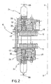
- Figure 2 shows a view in cross-section of the brake calliper in Figure 1 along the plane II in Figure 1,
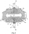
- Figure 3 shows a view in cross-section of the calliper in Figure 1 along the plane III in Figure 1,
- Figure 4 shows a magnified detail of the transmission coupling of the device according to the invention
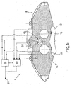
- Figure 5 shows a cross-sectional view of the brake calliper in Figure 1 along the line V-V in Figure 3,
- Figure 6 shows a view in cross-section of an immobilising device according to a further embodiment of the invention
- Figure 7 shows a perspective view of a brake calliper comprising an immobilising device according to a further embodiment of the invention
- Figure 8 shows a view in cross-section of the brake calliper in Figure 7 along the plane VIII in Figure 7.
- radial direction is meant a direction substantially perpendicular to the axis of rotation of the brake disc which is associated with the disc brake calliper.
- axial direction is meant a direction substantially parallel to the axis of rotation of the associated brake disc.
- tangential direction is meant a direction substantially perpendicular to the axial direction and the radial direction, and parallel to the braking band of the associated brake disc.
- 4 generically indicates a disc brake calliper complex mounted so as to straddle a brake disc 6 which can rotate about an axis X-X, which defines the axial direction, and comprising a braking band 7 having two braking surfaces 7A, 7B perpendicular to the axial direction and capable of exerting a braking action.
- Calliper complex 4 comprises a calliper body 8 comprising at least one central portion 9 straddling associated brake disc 6 and two side portions 10A, 10B located on sides axially opposite to brake disc 6 each respectively facing a corresponding braking surface 7A, 7B of braking band 7.
- Calliper complex 4 also comprises at least one pad 12 which can interact with brake disc 6, and at least one hydraulic actuating device 14 comprising at least one piston 16 which is mounted so as to move within calliper body 8 in an axial direction and capable of exerting a thrust force on pad 12 against brake disc 6.
- Calliper body 8 and the at least one piston 16 form a pressure chamber 20 capable of receiving a pressurised fluid to operate the at least one piston 16 and exert a braking force on brake disc 6.
- Calliper complex 4 also comprises at least one immobilising device 24 capable of immobilising brake disc 6, in particular acting as a parking brake.
- Immobilising device 24 comprises stop means 28 capable of providing an axial constraint for the said at least one pad 12 in a direction away from associated brake disc 6.
- stop means 28 are located on the side portions 10A, 10B of calliper body 8 and are at least partly housed within calliper body 8 itself.
- stop means 28 lie outside said pressure chamber 20; in other words they are fluidly isolated from pressure chamber 20.
- stop means 28 and the at least one piston 16 are operatively independent of each other; in other words there are no mechanical or hydraulic connections between stop means 28 and the at least one piston 16.
- Stop means 28 and the at least one piston 16 are positioned in such a way as to act on different portions of the said at least one pad 12 in other words; stop means 28 interact with a portion of pad 12 which is not acted on by the at least one piston 16.
- Stop means 28 and hydraulic actuating means 14 are operatively connected to a command device 29 and a control device 30.
- the command device is capable of activating stop means 28 and the control device 30 is capable of coordinating the functioning of stop means 28 in relation to hydraulic actuating device 14.
- Said control device 30 can be remote with respect to the calliper body or connected thereto.
- command device 29 and control device 30 are electrically connected to a power terminal 31 capable of receiving electrical current, for example a direct current.
- the stop means comprise a traveller 32 capable of acting on pad 12 and comprising a traveller body 36 and a traveller head 40.
- Traveller body 36 is at least partly housed within calliper body 8, in particular in a seat 44 in side portions 10A, 10B of calliper body 8.
- said seat 44 is a hole of cylindrical shape passing through a side portion of calliper body 8.
- On the inner surface seat 44 has a thread which extends along the axial direction.
- Seat 44 is aligned substantially parallel to pistons 16 and is fluidly separated from pistons 16 and pressure chamber 20.
- seat 44 comprises a bush 48 which has a thread 50 on its inner surface.
- bush 48 is inserted within seat 44 with an interference fit so as to render bush 48 of one piece with calliper body 8.
- a pin 52 located in for example a tangential direction, which passes through the side wall of bush 48 and part of the corresponding side portion of calliper body 8.
- Traveller body 36 is substantially cylindrical with a circular cross-section and has a thread on its outer surface which can make a connection of the bolt/nut type with bush 48, in which bush 48 constitutes the nut and traveller 32 constitutes the bolt.
- the thread of bush 48 and traveller 32 is of the irreversible type; in other words when a torque is applied to traveller 32 constituting the bolt it is possible to bring about relative axial translation movement between traveller 32 and bush 48, but it is not possible to effect relative translational movement by applying an axial force to traveller 32.
- traveller body 36 is operatively connected at one extremity 56 facing the brake disc to traveller head 40 which is substantially mushroom-shaped and capable of abutting against a portion of pad 12.
- traveller head 40 has a diameter which is larger than the diameter of traveller body 36 and has a flat portion 58 which can abut against a portion of pad 12.
- traveller body 36 has a hole 64, preferably a blind hole, that is one which does not pass through first extremity 56.
- Said hole 64 is preferably not circular, for example it is of rectangular shape with two opposite curved sides, illustrated for example in Figure 4, so as to be able to effect an interlocking connection with a corresponding shaft.
- Immobilising device 24 comprises an actuating shaft 68, at least partly within hole 64 in traveller body 36, and having a connecting extremity 72 and a transmission extremity 76.
- Connecting extremity 72 is shaped to match hole 64 in traveller body 36 so as to form an interlocking connection with traveller body 36 and bind together actuating shaft 68 and traveller 32 in rotation.
- Transmission extremity 76 is designed to receive the motion, directly or through suitable gears or transmissions from drive means 80.
- drive means 80 are electric motors, for example direct current motors, capable of providing a sufficient torque to cause actuating shaft 68 to rotate to bring about translational movement of traveller 32.
- drive means 80 and the part of the immobilising device which is not contained within the calliper body are housed in an enclosure 84 which according to the preferred arrangement and the dimensions required may be positioned substantially axially, as illustrated for example in Figures 1-3 and 7-8, or substantially tangentially, as illustrated for example in Figure 6.
- Enclosure 84 may be connected directly abutting against side portions 10A, 10B of calliper body 8, preferably with an intermediate sealing ring 85.
- the drive means comprise a drive shaft 86 having a free end 88 which is not engaged by visible transmission members, that is projecting from enclosure 84.
- Said free extremity 88 has a cross-section, for example a hexagonal cross-section, which is capable of being caused to rotate manually through a tool such as a hexagon spanner.
- Said enclosure 84 preferably comprises supports for the portion of actuating shaft 68 which projects from calliper body 8 away from brake disc 6; for example the support is provided by means of a bush bearing 92, which is substantially coaxial with the seat 44 of traveller body 36.
- the calliper body comprises at least two immobilising devices 24 located on opposite sides with respect to associated brake disc 6 and acting on pads 12 facing braking surfaces 7A, 7B which are axially opposite brake disc 6.
- immobilising device 24 is positioned on the side portions 10A, 10B of calliper body 8 in such a way that traveller head 40 can act on pad 12 in a substantially central portion of the pad with respect to a tangential direction.
- immobilising device 24 is preferably located close to the piston, for example in line with the tangential direction and located radially outwards, that is in a direction away from the axis of rotation of the associated brake disc.
- immobilising device 24 is preferably positioned in a position lying tangentially between the two pistons.
- an immobilising system comprising two immobilising devices 24A and 24B located on side portions 10A and 10B respectively, axially opposite each other with respect to associated brake disc 6, and operated by a single drive means 80 preferably located in the central portion 9 of one of the two side portions 10A, 10B of calliper body 8.
- said drive means 80 is located on side portion 10A and are operatively connected directly to actuating shaft 68 of immobilising device 24A located on the same side portion 10A.
- the immobilising devices each comprise a gear wheel 102A, 102B which is connected to each actuating shaft 68 so as to rotate as one piece.
- gear wheel 102A is positioned in an axial direction on the portion of actuating shaft 68 of immobilising device 24A lying between enclosure 84 and calliper body 8; gear wheel 102B is positioned in an axial direction on the free extremity 88 of the actuating shaft 68 of immobilising-device 24B.
- transmission device 96 which is positioned to straddle associated brake disc 6 and comprises a central shaft 10 and two lateral gears 104A, 104B capable of meshing with said gear wheels 102A, 102B, drive means 80 transmits rotatory motion to immobilising device 24 located on the opposite side portion 10B of calliper body 8.
- Braking for the purpose of parking using the immobilising device according to the invention is performed in at least two stages of braking.
- the hydraulic circuit of brake calliper 4 actuates the at least one piston 16 in such a way as to bring pad 12 on which the former acts to abut against brake disc 6 and immobilise brake disc 6.
- traveller body 36 is substantially withdrawn within seat 44 and the head of thrust member 40 is not in contact with pad 12.
- Actuation of the hydraulic or servo circuit may occur in different ways depending upon the nature of the braking system to which the brake calliper is operatively connected.
- drive means 80 are activated so as to cause actuating shaft 68 to rotate and move traveller 32 laterally until traveller head 40 abuts against pad 12.
- Electric motors such as motors fed with direct current, may for example be used as drive means 80.
- drive means 80 become deactivated, pressure is released from the hydraulic system and traveller head 40 remains abutted against pad 12 which is immobilised against brake disc 6.
- Drive means 80 may be deactivated for example by applying a control to the current taken up by the electric motor through control -device 30 so as to deactivate the drive means when this current reaches a predetermined value as a result of the resistance offered by the contact between traveller head 40 and pad 12. The irreversibility of the nut and bolt connection between traveller 32 and calliper body 8 prevents traveller head 40 from moving backwards.
- Traveller 32 has the function of acting as a stop for pad 12 after the latter has been positioned and abutted against brake disc 6 by hydraulic piston 16.
- Hydraulic actuating device 14 and immobilising device 24 are mechanically independent of each other while immobilising device 24 is functionally dependent on hydraulic actuating device 14 in that it is not capable of abutting and tightening pad 12 against the disc but only abutting traveller head 40 against the same in such a way as to prevent axial movement of pad 12 in a direction away from brake disc 6 when the force of hydraulic actuating device 14 is released.
- hydraulic actuating device 14 tightens pistons 16 against pads 12 in such a way as to preload and elastically deform calliper body 8; in particular calliper body 8 deforms elastically so that said side portions 10A, 10B tend to move axially away from the associated brake disc; in this way calliper body 8 is preloaded and stores elastic potential energy.
- traveller 32 abuts against pad 12 in such a way that when the hydraulic force of hydraulic actuating device 14 ceases the calliper body tends to give up the stored elastic potential energy, axially pressing said side portions 10A, 10B towards the associated brake disc.
- traveller 32 is axially loaded under compression and presses pad 12 against brake disc 6, ensuring that the disc is immobilised.
- Traveller 32' acts from a compression-loaded strut in such a way as to hold the calliper body in an elastically deformed state even after hydraulic actuating device 14 has been deactivated.
- control device carries out at least one second stage of braking in'association with at least one first stage of braking.
- control device again actuates hydraulic actuating device 14 in such a way as to further press pad 12 against brake disc 6; at the same time immobilising device 24 causes traveller 32 to advance further abutting against pad 12 in such a way as to ensure contact between pad 12 and traveller 32.
- control device 30 coordinates a sequence of first and second stages of braking which overlap at least partly with each other so as to ensure correct immobilisation of brake disc 6 through successively abutting hydraulic actuating device 14 against pads 12 and consequent secure immobilisation of traveller 32.
- hydraulic actuating device 14 In order to effect the operation of releasing the parking brake it is necessary during a first release stage to activate hydraulic actuating device 14 in such a way as to push pistons 16 against pads 12 and to relieve or preferably eliminate the axial load on traveller 32; in other words hydraulic actuating device 14 deforms calliper body 8 elastically in such a way as to relieve the compression load acting on traveller 32.
- control device activates drive means 80 which rotate traveller 32 in such a way as to move it away from pad 12; during this stage the control device for example controls the rate of rotation of drive means 80.
- drive means 80 which rotate traveller 32 in such a way as to move it away from pad 12; during this stage the control device for example controls the rate of rotation of drive means 80.
- Drive means 80 return traveller 32 towards calliper body 8 into a retracted position; control of the retraction of immobilising device 24 may take place for example by measuring the current taken up by drive means 80. The control device then deactivates drive means 80 and hydraulic actuating device 14 so as to discharge the hydraulic pressure in the hydraulic braking circuit.
- Control device 30 controls the operation of command device 29, preferably by acting on the current sent to the command device.
- Control device 30 controls command device 29 on the basis of a number of parameters which it receives from the stop means, such as for example the current taken up or the speed of rotation. On the basis of these parameters the control device acts on the command device which directly commands stop means 28.
- the control device In the case of callipers for disc brakes in which the pads are pushed by electric motors, the control device also obtains electrical signals from those electric motors acting on the pads and controls the command device on the basis of those signals.
- the command device in turn commands both the stop means and the thrust electric motors for the pads.
- the immobilising device according to this invention makes it possible to overcome the disadvantages inherent in the parking brake devices according to the known art.
- the device is free from the risks of hazardous leakage of brake fluid, as it is fluidly separate from the hydraulic circuit of the brake calliper with which it does not interfere.
- a further advantage lies in the fact that the device is of small dimensions and of low weight. In fact t he drive means are dimensioned to move the traveller from a resting position to a working position without exerting a thrust force on the pad.
- control device Through alternating successive stages of braking the control device guarantees correct seating of the pad against the brake disc and secure immobilisation of the disc even after pressure has been removed from the hydraulic braking system.
- the pad actuating device may not be hydraulic, and electrical actuating means such as direct current electric motors capable of forcing the pads against the brake disc may be used.
Landscapes
- Engineering & Computer Science (AREA)
- General Engineering & Computer Science (AREA)
- Mechanical Engineering (AREA)
- Braking Arrangements (AREA)
Abstract
Description
- This invention relates to an immobilising device for disk brakes and a corresponding method of use; in particular the invention relates to a device for providing a parking brake suitable for fitting to disc brakes.
- As is known, thrust mechanisms which tighten the pads against the brake disc which has to be immobilised, to ensure that the pads are in a position pressed against the brake disc, are provided in devices for parking brakes.
- These known mechanisms are complex and costly to construct; in particular thrust means or components which pass through the pressure chamber of the brake containing brake fluid under pressure are provided and interact with the thrust means for the braking systems, typically hydraulic pistons.
- Brake callipers are of more complex construction and problems with the hydraulic seal of the brake pressure chambers arise and can cause hazardous leaking of brake fluid such as to compromise operation of the calliper. Such callipers are known from
JP110093991 - The problem in this invention is that of constructing an immobilising device for disc brakes which overcomes the abovementioned disadvantages relating to the known art.
- These disadvantages and limitations are overcome by an immobilising device according to claim 1 the method according to claim 13 and the brake calliper to claims 18 to 20.
- Other embodiments of the immobilising device according to the invention are described in the subsequent claims.
- Other advantages and characteristics of the present invention will become clear from the following detailed description which is given with reference to the appended drawings which are provided purely by way of non-limiting example and in which:
- Figure 1 shows a perspective view of a brake calliper comprising an immobilising device according to the invention,
- Figure 2 shows a view in cross-section of the brake calliper in Figure 1 along the plane II in Figure 1,
- Figure 3 shows a view in cross-section of the calliper in Figure 1 along the plane III in Figure 1,
- Figure 4 shows a magnified detail of the transmission coupling of the device according to the invention,
- Figure 5 shows a cross-sectional view of the brake calliper in Figure 1 along the line V-V in Figure 3,
- Figure 6 shows a view in cross-section of an immobilising device according to a further embodiment of the invention,
- Figure 7 shows a perspective view of a brake calliper comprising an immobilising device according to a further embodiment of the invention,
- Figure 8 shows a view in cross-section of the brake calliper in Figure 7 along the plane VIII in Figure 7.
- Components or parts of components which are common to the embodiments described below will be indicated using the same reference numbers.
- By the term radial direction is meant a direction substantially perpendicular to the axis of rotation of the brake disc which is associated with the disc brake calliper.
- By the term axial direction is meant a direction substantially parallel to the axis of rotation of the associated brake disc.
- By the term tangential direction is meant a direction substantially perpendicular to the axial direction and the radial direction, and parallel to the braking band of the associated brake disc.
- The description below relates to disc brake callipers of both the fixed and floating type, comprising one piece or comprising two half callipers connected together.
- With reference to the abovementioned figures, 4 generically indicates a disc brake calliper complex mounted so as to straddle a brake disc 6 which can rotate about an axis X-X, which defines the axial direction, and comprising a
braking band 7 having two braking surfaces 7A, 7B perpendicular to the axial direction and capable of exerting a braking action. -
Calliper complex 4 comprises acalliper body 8 comprising at least onecentral portion 9 straddling associated brake disc 6 and two side portions 10A, 10B located on sides axially opposite to brake disc 6 each respectively facing a corresponding braking surface 7A, 7B ofbraking band 7. -
Calliper complex 4 also comprises at least onepad 12 which can interact with brake disc 6, and at least onehydraulic actuating device 14 comprising at least onepiston 16 which is mounted so as to move withincalliper body 8 in an axial direction and capable of exerting a thrust force onpad 12 against brake disc 6. -
Calliper body 8 and the at least onepiston 16 form apressure chamber 20 capable of receiving a pressurised fluid to operate the at least onepiston 16 and exert a braking force on brake disc 6. - Calliper
complex 4 also comprises at least oneimmobilising device 24 capable of immobilising brake disc 6, in particular acting as a parking brake. -
Immobilising device 24 comprises stop means 28 capable of providing an axial constraint for the said at least onepad 12 in a direction away from associated brake disc 6. - Preferably stop means 28 are located on the side portions 10A, 10B of
calliper body 8 and are at least partly housed withincalliper body 8 itself. - Advantageously stop means 28 lie outside said
pressure chamber 20; in other words they are fluidly isolated frompressure chamber 20. - Advantageously stop means 28 and the at least one
piston 16 are operatively independent of each other; in other words there are no mechanical or hydraulic connections between stop means 28 and the at least onepiston 16. - Stop means 28 and the at least one
piston 16 are positioned in such a way as to act on different portions of the said at least onepad 12 in other words; stop means 28 interact with a portion ofpad 12 which is not acted on by the at least onepiston 16. - Stop means 28 and hydraulic actuating means 14 are operatively connected to a
command device 29 and acontrol device 30. The command device is capable of activating stop means 28 and thecontrol device 30 is capable of coordinating the functioning of stop means 28 in relation tohydraulic actuating device 14. Saidcontrol device 30 can be remote with respect to the calliper body or connected thereto. Preferablycommand device 29 andcontrol device 30 are electrically connected to apower terminal 31 capable of receiving electrical current, for example a direct current. - In accordance with one embodiment the stop means comprise a
traveller 32 capable of acting onpad 12 and comprising atraveller body 36 and atraveller head 40. -
Traveller body 36 is at least partly housed withincalliper body 8, in particular in aseat 44 in side portions 10A, 10B ofcalliper body 8. - Preferably said
seat 44 is a hole of cylindrical shape passing through a side portion ofcalliper body 8. On theinner surface seat 44 has a thread which extends along the axial direction. -
Seat 44 is aligned substantially parallel topistons 16 and is fluidly separated frompistons 16 andpressure chamber 20. - According to a
further embodiment seat 44 comprises abush 48 which has athread 50 on its inner surface. Preferablybush 48 is inserted withinseat 44 with an interference fit so as to renderbush 48 of one piece withcalliper body 8. In particular, in order to prevent relative rotational movement betweenbush 48 andcalliper body 8, provision is made for example for apin 52, located in for example a tangential direction, which passes through the side wall ofbush 48 and part of the corresponding side portion ofcalliper body 8. -
Traveller body 36 is substantially cylindrical with a circular cross-section and has a thread on its outer surface which can make a connection of the bolt/nut type withbush 48, in whichbush 48 constitutes the nut andtraveller 32 constitutes the bolt. - Preferably the thread of
bush 48 andtraveller 32 is of the irreversible type; in other words when a torque is applied totraveller 32 constituting the bolt it is possible to bring about relative axial translation movement betweentraveller 32 andbush 48, but it is not possible to effect relative translational movement by applying an axial force totraveller 32. - Preferably
traveller body 36 is operatively connected at oneextremity 56 facing the brake disc totraveller head 40 which is substantially mushroom-shaped and capable of abutting against a portion ofpad 12. - Preferably
traveller head 40 has a diameter which is larger than the diameter oftraveller body 36 and has aflat portion 58 which can abut against a portion ofpad 12. - At a
second extremity 60 which is axially opposite saidfirst extremity 56traveller body 36 has ahole 64, preferably a blind hole, that is one which does not pass throughfirst extremity 56. - Said
hole 64 is preferably not circular, for example it is of rectangular shape with two opposite curved sides, illustrated for example in Figure 4, so as to be able to effect an interlocking connection with a corresponding shaft. -
Immobilising device 24 comprises anactuating shaft 68, at least partly withinhole 64 intraveller body 36, and having a connecting extremity 72 and atransmission extremity 76. - Connecting extremity 72 is shaped to match
hole 64 intraveller body 36 so as to form an interlocking connection withtraveller body 36 and bind together actuatingshaft 68 andtraveller 32 in rotation. -
Transmission extremity 76 is designed to receive the motion, directly or through suitable gears or transmissions fromdrive means 80. - Preferably drive means 80 are electric motors, for example direct current motors, capable of providing a sufficient torque to cause actuating
shaft 68 to rotate to bring about translational movement oftraveller 32. - Preferably drive means 80 and the part of the immobilising device which is not contained within the calliper body are housed in an
enclosure 84 which according to the preferred arrangement and the dimensions required may be positioned substantially axially, as illustrated for example in Figures 1-3 and 7-8, or substantially tangentially, as illustrated for example in Figure 6. -
Enclosure 84 may be connected directly abutting against side portions 10A, 10B ofcalliper body 8, preferably with anintermediate sealing ring 85. - According to one possible embodiment, illustrated for example in Figure 6, the drive means comprise a
drive shaft 86 having afree end 88 which is not engaged by visible transmission members, that is projecting fromenclosure 84. - Said
free extremity 88 has a cross-section, for example a hexagonal cross-section, which is capable of being caused to rotate manually through a tool such as a hexagon spanner. - Said
enclosure 84 preferably comprises supports for the portion of actuatingshaft 68 which projects fromcalliper body 8 away from brake disc 6; for example the support is provided by means of a bush bearing 92, which is substantially coaxial with theseat 44 oftraveller body 36. - Preferably, in the case described as an example, the calliper body comprises at least two
immobilising devices 24 located on opposite sides with respect to associated brake disc 6 and acting onpads 12 facing braking surfaces 7A, 7B which are axially opposite brake disc 6. - Preferably immobilising
device 24 is positioned on the side portions 10A, 10B ofcalliper body 8 in such a way thattraveller head 40 can act onpad 12 in a substantially central portion of the pad with respect to a tangential direction. - If the side portion of the calliper body has a
single piston 16 located centrally with respect to the pad,immobilising device 24 is preferably located close to the piston, for example in line with the tangential direction and located radially outwards, that is in a direction away from the axis of rotation of the associated brake disc. - If the side portion of the calliper body has two
pistons 16,immobilising device 24 is preferably positioned in a position lying tangentially between the two pistons. - According to a further embodiment, illustrated for example in Figures 7 and 8, provision is made for an immobilising system comprising two immobilising devices 24A and 24B located on side portions 10A and 10B respectively, axially opposite each other with respect to associated brake disc 6, and operated by a single drive means 80 preferably located in the
central portion 9 of one of the two side portions 10A, 10B ofcalliper body 8. - For example, said
drive means 80 is located on side portion 10A and are operatively connected directly to actuatingshaft 68 of immobilising device 24A located on the same side portion 10A. The immobilising devices each comprise a gear wheel 102A, 102B which is connected to each actuatingshaft 68 so as to rotate as one piece. - In particular, gear wheel 102A is positioned in an axial direction on the portion of actuating
shaft 68 of immobilising device 24A lying betweenenclosure 84 andcalliper body 8; gear wheel 102B is positioned in an axial direction on thefree extremity 88 of the actuatingshaft 68 of immobilising-device 24B. - Furthermore, through for example a
transmission device 96 which is positioned to straddle associated brake disc 6 and comprises acentral shaft 10 and two lateral gears 104A, 104B capable of meshing with said gear wheels 102A, 102B, drive means 80 transmits rotatory motion to immobilisingdevice 24 located on the opposite side portion 10B ofcalliper body 8. - The operation of the immobilising device according to the invention will now be described.
- Braking for the purpose of parking using the immobilising device according to the invention is performed in at least two stages of braking.
- During the first stage of parking braking the hydraulic circuit of
brake calliper 4 actuates the at least onepiston 16 in such a way as to bringpad 12 on which the former acts to abut against brake disc 6 and immobilise brake disc 6. In this first stage in which immobilisingdevice 24 is inactive or in a resting condition,traveller body 36 is substantially withdrawn withinseat 44 and the head ofthrust member 40 is not in contact withpad 12. - Actuation of the hydraulic or servo circuit may occur in different ways depending upon the nature of the braking system to which the brake calliper is operatively connected.
- In the second stage of parking braking, while the hydraulic circuit continues to press
pads 12 against brake disc 6, drive means 80 are activated so as to cause actuatingshaft 68 to rotate and movetraveller 32 laterally untiltraveller head 40 abuts againstpad 12. Electric motors, such as motors fed with direct current, may for example be used as drive means 80. - Once run ahead 40 abuts against
pad 12, drive means 80 become deactivated, pressure is released from the hydraulic system andtraveller head 40 remains abutted againstpad 12 which is immobilised against brake disc 6. Drive means 80 may be deactivated for example by applying a control to the current taken up by the electric motor through control -device 30 so as to deactivate the drive means when this current reaches a predetermined value as a result of the resistance offered by the contact betweentraveller head 40 andpad 12. The irreversibility of the nut and bolt connection betweentraveller 32 andcalliper body 8 preventstraveller head 40 from moving backwards. -
Traveller 32 has the function of acting as a stop forpad 12 after the latter has been positioned and abutted against brake disc 6 byhydraulic piston 16. - The immobilisation of brake disc 6 through
pads 12 takes place by taking advantage of the elasticity or elastic reaction force incalliper body 8. In other words, afterhydraulic actuating device 14 has operated,calliper body 8 tends to expand elastically under the effect of the hydraulic thrust so that aftertraveller 32 has abutted againstpad 12 and released pressure fromhydraulic actuating device 14, the preloading or elastic load stored in the calliper body tightenspad 12 which has first been locked in position bytraveller head 40 against brake disc 6. -
Hydraulic actuating device 14 and immobilisingdevice 24 are mechanically independent of each other while immobilisingdevice 24 is functionally dependent onhydraulic actuating device 14 in that it is not capable of abutting and tighteningpad 12 against the disc but only abuttingtraveller head 40 against the same in such a way as to prevent axial movement ofpad 12 in a direction away from brake disc 6 when the force ofhydraulic actuating device 14 is released. In other words,hydraulic actuating device 14 tightenspistons 16 againstpads 12 in such a way as to preload and elastically deformcalliper body 8; inparticular calliper body 8 deforms elastically so that said side portions 10A, 10B tend to move axially away from the associated brake disc; in thisway calliper body 8 is preloaded and stores elastic potential energy. Thentraveller 32 abuts againstpad 12 in such a way that when the hydraulic force ofhydraulic actuating device 14 ceases the calliper body tends to give up the stored elastic potential energy, axially pressing said side portions 10A, 10B towards the associated brake disc. Through this axialthrust force traveller 32 is axially loaded under compression and pressespad 12 against brake disc 6, ensuring that the disc is immobilised. Traveller 32' acts from a compression-loaded strut in such a way as to hold the calliper body in an elastically deformed state even afterhydraulic actuating device 14 has been deactivated. - Advantageously in the course of parking braking the control device carries out at least one second stage of braking in'association with at least one first stage of braking.
- In other words, after having pressed
pads 12 against brake disc 6 and abuttedtraveller 32 against the same, the control device again actuateshydraulic actuating device 14 in such a way as tofurther press pad 12 against brake disc 6; at the sametime immobilising device 24 causestraveller 32 to advance further abutting againstpad 12 in such a way as to ensure contact betweenpad 12 andtraveller 32. - Preferably control
device 30 coordinates a sequence of first and second stages of braking which overlap at least partly with each other so as to ensure correct immobilisation of brake disc 6 through successively abuttinghydraulic actuating device 14 againstpads 12 and consequent secure immobilisation oftraveller 32. - In order to effect the operation of releasing the parking brake it is necessary during a first release stage to activate
hydraulic actuating device 14 in such a way as to pushpistons 16 againstpads 12 and to relieve or preferably eliminate the axial load ontraveller 32; in other wordshydraulic actuating device 14 deformscalliper body 8 elastically in such a way as to relieve the compression load acting ontraveller 32. - In a second release stage the control device activates drive means 80 which rotate
traveller 32 in such a way as to move it away frompad 12; during this stage the control device for example controls the rate of rotation of drive means 80. According to further embodiments it is possible to movetraveller 32 away frompad 12 by providing power to drive means 80 for a predetermined period or controlling the number of rotations performed by drive means 80, or by using a limit switch capable of deactivating drive means 80 whentraveller head 40 has reached a predetermined position in its reverse travel. - Drive means 80
return traveller 32 towardscalliper body 8 into a retracted position; control of the retraction of immobilisingdevice 24 may take place for example by measuring the current taken up by drive means 80. The control device then deactivates drive means 80 andhydraulic actuating device 14 so as to discharge the hydraulic pressure in the hydraulic braking circuit. - In the event of malfunctioning, or jamming of
traveller head 40 againstpad 12 or damage to drive means 80, it is possible to act manually by rotatingdrive shaft 86 through a tool engaged on the oppositefree extremity 88 of that shaft. -
Control device 30 controls the operation ofcommand device 29, preferably by acting on the current sent to the command device.Control device 30 controls commanddevice 29 on the basis of a number of parameters which it receives from the stop means, such as for example the current taken up or the speed of rotation. On the basis of these parameters the control device acts on the command device which directly commands stop means 28. In the case of callipers for disc brakes in which the pads are pushed by electric motors, the control device also obtains electrical signals from those electric motors acting on the pads and controls the command device on the basis of those signals. The command device in turn commands both the stop means and the thrust electric motors for the pads. - As can be appreciated from what has been described, the immobilising device according to this invention makes it possible to overcome the disadvantages inherent in the parking brake devices according to the known art.
- In particular the device described is simple and cheap to manufacture.
- The device is free from the risks of hazardous leakage of brake fluid, as it is fluidly separate from the hydraulic circuit of the brake calliper with which it does not interfere.
- Furthermore, if the immobilising device is damaged there is no risk of hazardous malfunction of the hydraulic servo braking system.
- A further advantage lies in the fact that the device is of small dimensions and of low weight. In fact t he drive means are dimensioned to move the traveller from a resting position to a working position without exerting a thrust force on the pad.
- Through alternating successive stages of braking the control device guarantees correct seating of the pad against the brake disc and secure immobilisation of the disc even after pressure has been removed from the hydraulic braking system.
- In fact because of the fact that the piston and the traveller act on different portions of the pad small misalignments may arise due to elastic yielding of the calliper body after pressure has been removed from the hydraulic circuit of the calliper. This play will not ensure safe immobilisation of the disc through the traveller alone. These phenomena are avoided thanks to the immobilisation method described above imposed by the control device.
- In order to satisfy contingent and specific requirements a person skilled in the art may make many modifications and variants to the immobilising device described above.
- For example the pad actuating device may not be hydraulic, and electrical actuating means such as direct current electric motors capable of forcing the pads against the brake disc may be used.
- These and other modifications and variants are all however included within the scope of the invention as defined by the following claims.
Claims (20)
- Immobilising device (24) for a disc brake capable of effecting a parking braking action on a brake disc (6) which can rotate about an axis (X), the said disc brake comprising- a calliper body (8),- at least one pad (12) capable of interacting with the said brake disc (6), at least one hydraulic actuating device (14) comprising at least one piston (16) mounted so as to move within the calliper body (8) in an axial direction parallel to the said axis (X) and capable of exerting the thrust force through the said pad (12) against the said brake disc (6), the said immobilising device (24) comprising- stop means (28) capable of applying an axial constraint on the said at least one pad (12) in a direction away from the associated brake disc (6),characterised in that
the said stop means (28) are operatively separated from the at least one piston (16) and abut against a portion of the said pad (12) which is not acted on by the at least one piston (16), preventing axial displacement of the pad (12) in a direction away from the associated brake disc (6), the stop means comprising a traveller (32) acting from a compression - loaded strut in such a way as to hold the calliper body in an elastically deformed state even after hydraulic actuating device (14) has been deactivated, the traveller (32) being axially loaded under compression and pressing pad (12) against brake disc (6), ensuring that the disc is immobilised, the said hydraulic actuating device (14) and the said stop means (28) being operatively associated with a control device for simultaneous and/or sequential operation of the same. - Immobilising device (24) according to claim 1, in which the said stop means (28) lie outside a pressure chamber (20) of the calliper body (8) designed to receive pressurised fluid to actuate the at least one piston (16).
- Immobilising device (24) according to claims 1 or 2, in which the said stop means (28) comprise a traveller (32) acting directly on the at least one pad (12) and comprising a traveller body (36) at least partly housed within the calliper body (8) and a traveller head (40) capable of abutting against the at least one pad (12).
- Immobilising means (24) according to claim 3, in which the said traveller head (40) is substantially mushroom-shaped.
- Immobilising device (24) according to claims 3 or 4, in which the said traveller body (36) is at least partly connected to the calliper body (8) in accordance with a connection of the nut and bolt type.
- Immobilising device (24) according to any one of the preceding claims, in which the said traveller body (36) is at least partly connected to the calliper body (8) through a bush (48) securely fixed to the calliper body (8) and connected to the traveller body (36) through a connection of the nut and bolt type.
- Immobilising device (24) according to claims 5 or 6, in which the said nut and bolt connection is of the irreversible type.
- Immobilising device (24) according to any one of claims 3 to 7, in which the said traveller body (36) is connected to an actuating shaft (68) for the traveller (32) in such a way that the traveller body (36) and the said actuating shaft (68) rotate together as one piece.
- Immobilising device (24) according to claim 8, in which the traveller body (36) and the actuating shaft (68) are firmly connected in rotation through an interlocking connection.
- Immobilising device (24) according to claims 8 or 9, in which the said actuating shaft (68) is operatively associated with drive means (80) capable of rotating the said actuating shaft (68).
- Immobilising device (24) according to any one of the preceding claims, in which the said drive means (80) are located substantially parallel to the said drive shaft (68).
- Immobilising device (24) according to any one of claims from 1 to 10, in which the said drive means (80) are located along an angled direction with respect to the said actuating shaft (68).
- Method for the parking braking of a disc brake through an immobilising device (24) according to any one of claims from 1 to 12, comprising
a first braking stage in which the said at least one piston (16) pushes the said at least one pad (12) to abut against the brake disc (6) in such a way as to immobilise the brake disc (6), the hydraulic actuating device 14 tightening pistons 16 against pads 12 in such a way as to preload and elastically deform calliper body 8, calliper body 8 being preloaded and storing elastic potential energy, and
a second braking stage in which the said stop means (28) abut against a portion of the said at least one pad (12) not acted on by the said piston (26) preventing axial displacement of the pad (12) in a direction away from the associated brake disc (6), in such a way that when the hydraulic force of hydraulic actuating device (14) ceases the calliper body tends to give up the stored elastic potential energy, axially pressing said side portions (10A, 10B) towards the associated brake disc, ensuring that the disc is immobilised. - Method for the parking braking of a disc brake according to claim 13, in which the said first and second braking stages overlap at least partly in time.
- Method of parking braking a disc brake according to claim 13 or 14, in which a sequence of first braking stages is provided during operation.
- Method for parking braking a disc brake according to any one of claims from 13 to 15, comprising
a first release stage in which the said at least one piston (16) presses the said at least one pad (12) against the brake disc (6) in such a way as to relieve the axial load on the stop means (28), and
a second release stage in which the said drive means (80) cause the said stop means (28) to move back in a direction away from the brake disc (6). - Method of parking braking a disc brake according to claim 16, comprising a third release stage in which hydraulic pressure is discharged from the said hydraulic actuating device (14).
- Brake calliper comprising at least one immobilising device (24) according to any one of claims from 1 to 12.
- Brake calliper (4) of the fixed type, comprising at least one pair of immobilising devices (24) according to any of claims from 1 to 12, the said immobilising devices (24) being located on opposite sides with respect to the brake disc (6) in such a way as to act upon pads (12) located on opposite sides of the said brake disc (6).
- Brake calliper (4) of the floating type, comprising at least one immobilising device (24) according to claims 1 to 12, located on one side of the calliper body (8) comprising at least one piston (16).
Applications Claiming Priority (1)
| Application Number | Priority Date | Filing Date | Title |
|---|---|---|---|
| PCT/IT2003/000766 WO2005050050A1 (en) | 2003-11-24 | 2003-11-24 | Immobilising device for a disc brake and corresponding method of use |
Publications (2)
| Publication Number | Publication Date |
|---|---|
| EP1687547A1 EP1687547A1 (en) | 2006-08-09 |
| EP1687547B1 true EP1687547B1 (en) | 2008-01-30 |
Family
ID=34611211
Family Applications (1)
| Application Number | Title | Priority Date | Filing Date |
|---|---|---|---|
| EP03768119A Expired - Lifetime EP1687547B1 (en) | 2003-11-24 | 2003-11-24 | Immobilising device for a disc brake and corresponding method of use |
Country Status (5)
| Country | Link |
|---|---|
| EP (1) | EP1687547B1 (en) |
| AT (1) | ATE385299T1 (en) |
| AU (1) | AU2003292537A1 (en) |
| DE (1) | DE60318967D1 (en) |
| WO (1) | WO2005050050A1 (en) |
Cited By (1)
| Publication number | Priority date | Publication date | Assignee | Title |
|---|---|---|---|---|
| WO2012172317A1 (en) | 2011-06-13 | 2012-12-20 | Trw Limited | Electronic park brake |
Families Citing this family (2)
| Publication number | Priority date | Publication date | Assignee | Title |
|---|---|---|---|---|
| CN115059707B (en) * | 2022-07-15 | 2024-02-09 | 晋江市凯燕新材料研究院股份有限公司 | Braking system when disc surface and edge surface are different |
| IT202300006795A1 (en) * | 2023-04-06 | 2024-10-06 | Brembo Spa | Disc brake brake caliper |
Family Cites Families (6)
| Publication number | Priority date | Publication date | Assignee | Title |
|---|---|---|---|---|
| ES344660A1 (en) * | 1966-12-16 | 1968-10-16 | Teves Kg Alfred | Dual-network wheel-brake arrangement |
| DE1680832B2 (en) * | 1968-01-19 | 1972-12-14 | Alfred Teves Gmbh, 6000 Frankfurt | HAND BRAKE DEVICE FOR A PRESSURE-ACTUATED FIXED CALIPER DISC BRAKE, ESPECIALLY FOR MOTOR VEHICLES |
| US3809191A (en) * | 1969-08-04 | 1974-05-07 | Index Ind Inc | Auxiliary braking system |
| US3734248A (en) * | 1971-12-01 | 1973-05-22 | C Fay | Floating caliper assembly for distribution of brake shoe thrust in dual hydraulic brake system |
| JPH0654457B2 (en) * | 1989-01-27 | 1994-07-20 | 株式会社日立製作所 | Data processing device |
| JPH1193991A (en) * | 1997-09-22 | 1999-04-06 | Tokico Ltd | Brake equipment |
-
2003
- 2003-11-24 EP EP03768119A patent/EP1687547B1/en not_active Expired - Lifetime
- 2003-11-24 DE DE60318967T patent/DE60318967D1/en not_active Expired - Lifetime
- 2003-11-24 WO PCT/IT2003/000766 patent/WO2005050050A1/en not_active Ceased
- 2003-11-24 AU AU2003292537A patent/AU2003292537A1/en not_active Abandoned
- 2003-11-24 AT AT03768119T patent/ATE385299T1/en not_active IP Right Cessation
Cited By (1)
| Publication number | Priority date | Publication date | Assignee | Title |
|---|---|---|---|---|
| WO2012172317A1 (en) | 2011-06-13 | 2012-12-20 | Trw Limited | Electronic park brake |
Also Published As
| Publication number | Publication date |
|---|---|
| ATE385299T1 (en) | 2008-02-15 |
| EP1687547A1 (en) | 2006-08-09 |
| DE60318967D1 (en) | 2008-03-20 |
| AU2003292537A1 (en) | 2005-06-08 |
| WO2005050050A1 (en) | 2005-06-02 |
Similar Documents
| Publication | Publication Date | Title |
|---|---|---|
| CN114423962B (en) | Hydraulic and electromechanical service and parking disc brakes | |
| KR930002425B1 (en) | Electrically operated disc brake with back-off protector | |
| EP0551397B1 (en) | Disk brake/parking brake | |
| US12228185B2 (en) | Disk brake | |
| KR910007579B1 (en) | Electric disc brake | |
| US20200217379A1 (en) | Electric motor-driven brake apparatus | |
| KR102326495B1 (en) | Electromechanically and hydraulically actuatable motor vehicle brake with selective self-locking | |
| CN111133217B (en) | Electric Disc Brake | |
| CN109219544B (en) | Disc brakes | |
| KR102671511B1 (en) | Actuator and electro-mechanical brake having the same | |
| JP2014070670A (en) | Disc brake | |
| KR20130034605A (en) | Disk brake | |
| US20090159381A1 (en) | Hydraulically actuable vehicle brake having a locking means | |
| CN107250592B (en) | Disc brakes | |
| US20070029142A1 (en) | Brake system including ball screw and nut assembly | |
| KR20210002010A (en) | Electro-mechanical brake system | |
| JP5968192B2 (en) | Disc brake | |
| WO2015151618A1 (en) | Disk brake | |
| GB2329435A (en) | Apparatus for actuating a vehicle brake | |
| EP1687547A1 (en) | Immobilising device for a disc brake and corresponding method of use | |
| US20230091307A1 (en) | Brake device | |
| KR20110073889A (en) | Axle device for construction machinery with parking brake | |
| CN220706282U (en) | Electronic brake caliper assembly with electronic parking function | |
| US9132809B2 (en) | Integrated parking brake for disc brake | |
| US20070102249A1 (en) | Automatically locking parking brake for a vehicle |
Legal Events
| Date | Code | Title | Description |
|---|---|---|---|
| PUAI | Public reference made under article 153(3) epc to a published international application that has entered the european phase |
Free format text: ORIGINAL CODE: 0009012 |
|
| 17P | Request for examination filed |
Effective date: 20060328 |
|
| AK | Designated contracting states |
Kind code of ref document: A1 Designated state(s): AT BE BG CH CY CZ DE DK EE ES FI FR GB GR HU IE IT LI LU MC NL PT RO SE SI SK TR |
|
| 17Q | First examination report despatched |
Effective date: 20061201 |
|
| DAX | Request for extension of the european patent (deleted) | ||
| GRAP | Despatch of communication of intention to grant a patent |
Free format text: ORIGINAL CODE: EPIDOSNIGR1 |
|
| GRAS | Grant fee paid |
Free format text: ORIGINAL CODE: EPIDOSNIGR3 |
|
| GRAA | (expected) grant |
Free format text: ORIGINAL CODE: 0009210 |
|
| AK | Designated contracting states |
Kind code of ref document: B1 Designated state(s): AT BE BG CH CY CZ DE DK EE ES FI FR GB GR HU IE IT LI LU MC NL PT RO SE SI SK TR |
|
| REG | Reference to a national code |
Ref country code: GB Ref legal event code: FG4D |
|
| REG | Reference to a national code |
Ref country code: CH Ref legal event code: EP |
|
| REG | Reference to a national code |
Ref country code: IE Ref legal event code: FG4D |
|
| REF | Corresponds to: |
Ref document number: 60318967 Country of ref document: DE Date of ref document: 20080320 Kind code of ref document: P |
|
| PG25 | Lapsed in a contracting state [announced via postgrant information from national office to epo] |
Ref country code: LI Free format text: LAPSE BECAUSE OF FAILURE TO SUBMIT A TRANSLATION OF THE DESCRIPTION OR TO PAY THE FEE WITHIN THE PRESCRIBED TIME-LIMIT Effective date: 20080130 Ref country code: CH Free format text: LAPSE BECAUSE OF FAILURE TO SUBMIT A TRANSLATION OF THE DESCRIPTION OR TO PAY THE FEE WITHIN THE PRESCRIBED TIME-LIMIT Effective date: 20080130 Ref country code: ES Free format text: LAPSE BECAUSE OF FAILURE TO SUBMIT A TRANSLATION OF THE DESCRIPTION OR TO PAY THE FEE WITHIN THE PRESCRIBED TIME-LIMIT Effective date: 20080511 Ref country code: FI Free format text: LAPSE BECAUSE OF FAILURE TO SUBMIT A TRANSLATION OF THE DESCRIPTION OR TO PAY THE FEE WITHIN THE PRESCRIBED TIME-LIMIT Effective date: 20080130 |
|
| NLV1 | Nl: lapsed or annulled due to failure to fulfill the requirements of art. 29p and 29m of the patents act | ||
| REG | Reference to a national code |
Ref country code: CH Ref legal event code: PL |
|
| PG25 | Lapsed in a contracting state [announced via postgrant information from national office to epo] |
Ref country code: AT Free format text: LAPSE BECAUSE OF FAILURE TO SUBMIT A TRANSLATION OF THE DESCRIPTION OR TO PAY THE FEE WITHIN THE PRESCRIBED TIME-LIMIT Effective date: 20080130 |
|
| PG25 | Lapsed in a contracting state [announced via postgrant information from national office to epo] |
Ref country code: PT Free format text: LAPSE BECAUSE OF FAILURE TO SUBMIT A TRANSLATION OF THE DESCRIPTION OR TO PAY THE FEE WITHIN THE PRESCRIBED TIME-LIMIT Effective date: 20080630 Ref country code: BE Free format text: LAPSE BECAUSE OF FAILURE TO SUBMIT A TRANSLATION OF THE DESCRIPTION OR TO PAY THE FEE WITHIN THE PRESCRIBED TIME-LIMIT Effective date: 20080130 Ref country code: SI Free format text: LAPSE BECAUSE OF FAILURE TO SUBMIT A TRANSLATION OF THE DESCRIPTION OR TO PAY THE FEE WITHIN THE PRESCRIBED TIME-LIMIT Effective date: 20080130 |
|
| PG25 | Lapsed in a contracting state [announced via postgrant information from national office to epo] |
Ref country code: CZ Free format text: LAPSE BECAUSE OF FAILURE TO SUBMIT A TRANSLATION OF THE DESCRIPTION OR TO PAY THE FEE WITHIN THE PRESCRIBED TIME-LIMIT Effective date: 20080130 Ref country code: SK Free format text: LAPSE BECAUSE OF FAILURE TO SUBMIT A TRANSLATION OF THE DESCRIPTION OR TO PAY THE FEE WITHIN THE PRESCRIBED TIME-LIMIT Effective date: 20080130 Ref country code: DK Free format text: LAPSE BECAUSE OF FAILURE TO SUBMIT A TRANSLATION OF THE DESCRIPTION OR TO PAY THE FEE WITHIN THE PRESCRIBED TIME-LIMIT Effective date: 20080130 Ref country code: NL Free format text: LAPSE BECAUSE OF FAILURE TO SUBMIT A TRANSLATION OF THE DESCRIPTION OR TO PAY THE FEE WITHIN THE PRESCRIBED TIME-LIMIT Effective date: 20080130 Ref country code: SE Free format text: LAPSE BECAUSE OF FAILURE TO SUBMIT A TRANSLATION OF THE DESCRIPTION OR TO PAY THE FEE WITHIN THE PRESCRIBED TIME-LIMIT Effective date: 20080430 |
|
| EN | Fr: translation not filed | ||
| PG25 | Lapsed in a contracting state [announced via postgrant information from national office to epo] |
Ref country code: RO Free format text: LAPSE BECAUSE OF FAILURE TO SUBMIT A TRANSLATION OF THE DESCRIPTION OR TO PAY THE FEE WITHIN THE PRESCRIBED TIME-LIMIT Effective date: 20080130 |
|
| PLBE | No opposition filed within time limit |
Free format text: ORIGINAL CODE: 0009261 |
|
| STAA | Information on the status of an ep patent application or granted ep patent |
Free format text: STATUS: NO OPPOSITION FILED WITHIN TIME LIMIT |
|
| 26N | No opposition filed |
Effective date: 20081031 |
|
| PG25 | Lapsed in a contracting state [announced via postgrant information from national office to epo] |
Ref country code: DE Free format text: LAPSE BECAUSE OF FAILURE TO SUBMIT A TRANSLATION OF THE DESCRIPTION OR TO PAY THE FEE WITHIN THE PRESCRIBED TIME-LIMIT Effective date: 20080501 |
|
| PG25 | Lapsed in a contracting state [announced via postgrant information from national office to epo] |
Ref country code: BG Free format text: LAPSE BECAUSE OF FAILURE TO SUBMIT A TRANSLATION OF THE DESCRIPTION OR TO PAY THE FEE WITHIN THE PRESCRIBED TIME-LIMIT Effective date: 20080430 Ref country code: FR Free format text: LAPSE BECAUSE OF FAILURE TO SUBMIT A TRANSLATION OF THE DESCRIPTION OR TO PAY THE FEE WITHIN THE PRESCRIBED TIME-LIMIT Effective date: 20081121 Ref country code: EE Free format text: LAPSE BECAUSE OF FAILURE TO SUBMIT A TRANSLATION OF THE DESCRIPTION OR TO PAY THE FEE WITHIN THE PRESCRIBED TIME-LIMIT Effective date: 20080130 |
|
| PG25 | Lapsed in a contracting state [announced via postgrant information from national office to epo] |
Ref country code: MC Free format text: LAPSE BECAUSE OF NON-PAYMENT OF DUE FEES Effective date: 20081130 |
|
| PG25 | Lapsed in a contracting state [announced via postgrant information from national office to epo] |
Ref country code: CY Free format text: LAPSE BECAUSE OF FAILURE TO SUBMIT A TRANSLATION OF THE DESCRIPTION OR TO PAY THE FEE WITHIN THE PRESCRIBED TIME-LIMIT Effective date: 20080130 |
|
| PG25 | Lapsed in a contracting state [announced via postgrant information from national office to epo] |
Ref country code: IE Free format text: LAPSE BECAUSE OF NON-PAYMENT OF DUE FEES Effective date: 20081124 |
|
| PG25 | Lapsed in a contracting state [announced via postgrant information from national office to epo] |
Ref country code: HU Free format text: LAPSE BECAUSE OF FAILURE TO SUBMIT A TRANSLATION OF THE DESCRIPTION OR TO PAY THE FEE WITHIN THE PRESCRIBED TIME-LIMIT Effective date: 20080731 Ref country code: LU Free format text: LAPSE BECAUSE OF NON-PAYMENT OF DUE FEES Effective date: 20081124 |
|
| PG25 | Lapsed in a contracting state [announced via postgrant information from national office to epo] |
Ref country code: TR Free format text: LAPSE BECAUSE OF FAILURE TO SUBMIT A TRANSLATION OF THE DESCRIPTION OR TO PAY THE FEE WITHIN THE PRESCRIBED TIME-LIMIT Effective date: 20080130 |
|
| PG25 | Lapsed in a contracting state [announced via postgrant information from national office to epo] |
Ref country code: GR Free format text: LAPSE BECAUSE OF FAILURE TO SUBMIT A TRANSLATION OF THE DESCRIPTION OR TO PAY THE FEE WITHIN THE PRESCRIBED TIME-LIMIT Effective date: 20080501 |
|
| PGFP | Annual fee paid to national office [announced via postgrant information from national office to epo] |
Ref country code: IT Payment date: 20161108 Year of fee payment: 14 |
|
| PGFP | Annual fee paid to national office [announced via postgrant information from national office to epo] |
Ref country code: GB Payment date: 20171123 Year of fee payment: 15 |
|
| PG25 | Lapsed in a contracting state [announced via postgrant information from national office to epo] |
Ref country code: IT Free format text: LAPSE BECAUSE OF NON-PAYMENT OF DUE FEES Effective date: 20171124 |
|
| GBPC | Gb: european patent ceased through non-payment of renewal fee |
Effective date: 20181124 |
|
| PG25 | Lapsed in a contracting state [announced via postgrant information from national office to epo] |
Ref country code: GB Free format text: LAPSE BECAUSE OF NON-PAYMENT OF DUE FEES Effective date: 20181124 |