EP1685989A2 - Airflow distribution structure of vehicular air conditioning system - Google Patents
Airflow distribution structure of vehicular air conditioning system Download PDFInfo
- Publication number
- EP1685989A2 EP1685989A2 EP06000073A EP06000073A EP1685989A2 EP 1685989 A2 EP1685989 A2 EP 1685989A2 EP 06000073 A EP06000073 A EP 06000073A EP 06000073 A EP06000073 A EP 06000073A EP 1685989 A2 EP1685989 A2 EP 1685989A2
- Authority
- EP
- European Patent Office
- Prior art keywords
- duct
- airflow
- outlet
- strength member
- outlets
- Prior art date
- Legal status (The legal status is an assumption and is not a legal conclusion. Google has not performed a legal analysis and makes no representation as to the accuracy of the status listed.)
- Withdrawn
Links
Images









Classifications
-
- B—PERFORMING OPERATIONS; TRANSPORTING
- B60—VEHICLES IN GENERAL
- B60H—ARRANGEMENTS OF HEATING, COOLING, VENTILATING OR OTHER AIR-TREATING DEVICES SPECIALLY ADAPTED FOR PASSENGER OR GOODS SPACES OF VEHICLES
- B60H1/00—Heating, cooling or ventilating devices
- B60H1/00507—Details, e.g. mounting arrangements, desaeration devices
- B60H1/00514—Details of air conditioning housings
- B60H1/0055—Details of air conditioning housings the housing or parts thereof being integrated in other devices, e.g. dashboard
-
- B—PERFORMING OPERATIONS; TRANSPORTING
- B60—VEHICLES IN GENERAL
- B60H—ARRANGEMENTS OF HEATING, COOLING, VENTILATING OR OTHER AIR-TREATING DEVICES SPECIALLY ADAPTED FOR PASSENGER OR GOODS SPACES OF VEHICLES
- B60H1/00—Heating, cooling or ventilating devices
- B60H1/00507—Details, e.g. mounting arrangements, desaeration devices
- B60H1/00557—Details of ducts or cables
- B60H1/00564—Details of ducts or cables of air ducts
-
- B—PERFORMING OPERATIONS; TRANSPORTING
- B60—VEHICLES IN GENERAL
- B60H—ARRANGEMENTS OF HEATING, COOLING, VENTILATING OR OTHER AIR-TREATING DEVICES SPECIALLY ADAPTED FOR PASSENGER OR GOODS SPACES OF VEHICLES
- B60H1/00—Heating, cooling or ventilating devices
- B60H1/24—Ventilating devices where the heating or cooling is irrelevant
- B60H1/241—Ventilating devices where the heating or cooling is irrelevant characterised by the location of ventilation devices in the vehicle
- B60H1/242—Ventilating devices where the heating or cooling is irrelevant characterised by the location of ventilation devices in the vehicle located in the front area
-
- B—PERFORMING OPERATIONS; TRANSPORTING
- B62—LAND VEHICLES FOR TRAVELLING OTHERWISE THAN ON RAILS
- B62D—MOTOR VEHICLES; TRAILERS
- B62D25/00—Superstructure or monocoque structure sub-units; Parts or details thereof not otherwise provided for
- B62D25/08—Front or rear portions
- B62D25/14—Dashboards as superstructure sub-units
- B62D25/142—Dashboards as superstructure sub-units having ventilation channels incorporated therein
-
- B—PERFORMING OPERATIONS; TRANSPORTING
- B62—LAND VEHICLES FOR TRAVELLING OTHERWISE THAN ON RAILS
- B62D—MOTOR VEHICLES; TRAILERS
- B62D25/00—Superstructure or monocoque structure sub-units; Parts or details thereof not otherwise provided for
- B62D25/08—Front or rear portions
- B62D25/14—Dashboards as superstructure sub-units
- B62D25/145—Dashboards as superstructure sub-units having a crossbeam incorporated therein
Definitions
- the invention relates to an airflow distribution structure of a vehicular air conditioning system, and more particularly, to an airflow distribution structure for distributing conditioned air into the passenger room using a cross car beam.
- a cross car beam is positioned proximate to the boundary between an engine room and a passenger room in an automobile such that the cross car beam extends across a vehicle body.
- the cross car beam extends between both side surfaces of the vehicle body, and the opposite ends of the cross car beam are connected to the opposite inner side surfaces of the vehicle body.
- This structure reinforces rigidity of the vehicle body in the transverse direction, and receives an impact applied at the time of side collision.
- Japanese Patent Application Publication Laid-open No. H10-44762 describes a structure in which such a cross car beam is used as a duct of conditioned air from an air conditioning unit.
- the cross car beam 100 extends between both side walls 111. In this extending state, both ends of the cross car beam are fixed to both side walls 111 of the vehicle by bolts, welding, or the like and the cross car beam 100 stretches across the vehicle body 110 in the transverse direction.
- the cross car beam 100 reinforces the rigidity of the vehicle body 110 in the transverse direction.
- a shaft of a steering wheel 112 and an airbag are set in the vehicle body using the cross car beam 100.
- the cross car beam 100 has a hollow tube.
- the intermediate portion of the hollow tube is connected to a duct extending from a vehicular air conditioning unit (not illustrated) to introduce conditioned air from the air conditioning unit.
- the surface of the cross car beam 100 closer to the passenger room includes a plurality of outlets 120 for adjusting the temperature of air sent to a passenger on a driver's seat or on a passenger seat. Conditioned air from the air conditioning unit is blown out from the outlets 120.
- the tubular cross car beam 100 has the outlets for blowing out conditioned air, and the strength of the cross car beam 100 is deteriorated.
- the cross car beam 100 does not sufficiently reinforce the rigidity of the vehicle body in the transverse direction that is an original purpose of the cross car beam. If the thickness of the cross car beam is increased to enhance the strength, the cross car beam increases in weight, being not suitable for use in a vehicle.
- the cross car beam 100 includes a hollow tube, and the outlets 120 are provided in the hollow tube to blow conditioned air.
- This structure is difficult to control the blowing direction of the conditioned air.
- To control the conditioned air it is necessary to optimally set conditions such as opening positions and opening angles of the outlets. Such setting causes a complicated structure, so that the manufacture of the cross car beam is troublesome, difficult, and impractical.
- a duct member for controlling the conditioned air is incorporated in the cross car beam.
- This structure causes a complicated operation for assembling the duct member into the cross car beam and an operation for making the duct member as a passage for conditioned air, and increases the assembling steps.
- the first object of the invention is to provide an airflow distribution structure of a vehicular air conditioning system that sufficiently reinforces rigidity of a vehicle body in the transverse direction without deteriorating the strength even if a cross car beam is formed with outlets for conditioned air so that the cross car beam is used as a duct for conditioned air from an air conditioning system.
- the second object of the invention is to provide an airflow distribution structure of a vehicular air conditioning system in which, if a cross car beam is used as a duct for conditioned air, a duct member for controlling the blowing out of conditioned air is simply incorporated in the cross car beam, and the operability thereof is enhanced.
- the airflow distribution structure includes a tubular strength member (1; 40) extending behind an instrument panel (30) in a width direction of a vehicle and having both ends fixed to opposite side walls inside a passenger room, respectively.
- the strength member includes a first portion (13; 14) having an airflow passage (13; 14) therein.
- the strength member includes a second portion (19; 20) having a first outlet (15; 16) communicating with the airflow passage.
- the second portion (19; 20) is enlarged to be greater in tube dimension than the first portion (13; 14).
- the airflow distribution structure further includes a duct member (22; 23; 24) inside the strength member (1; 40), having the airflow passage (13; 14) therein and communicating with the first outlet (15; 16).
- the duct member includes a curved portion coinciding with the first outlet, the curved portion (23b; 24b) curving away from the first outlet to curve close to the first outlet.
- the first outlet includes first outlets (15; 16; 17; 18) in a longitudinal direction of the strength member.
- the second portion includes therein louvers (51; 52) switchable between the first outlets.
- the strength member (1; 40) has a first inlet (8; 9) communicating with the airflow passage (13; 14).
- the strength member has an end opening (17; 18) at the end thereof.
- the airflow distribution structure includes an airflow distribution duct having a second inlet (22f; 22g) facing the first inlet.
- the airflow distribution structure includes a fitting opening (22d; 22e) closer to outlet.
- the airflow distribution structure includes a branch duct (23; 24) having a connecting opening (23d; 24d) closer to inlet and fittable with the fitting opening; and a second outlet (23c; 24c) facing the first outlet (15; 16).
- the airflow distribution duct (22) is inserted into the strength member (1; 40) from the first outlet (8; 9).
- the branch duct (23; 24) is inserted into the strength member (1; 40) from the end opening (17; 18).
- the fitting opening (22d; 22e) and the connecting opening (23d; 24d) are fitted and communicate with each other.
- the tubular strength member defines an airflow passage and an outlet for conditioned airflow from an air conditioning unit, being used as a duct for conditioned airflow from an air conditioner.
- the second portion is greater in tube dimension than the first portion. This structure enhances the strength of the strength member, ensuring opening area of the first outlet. Thus, the strength member is not required to increase in thickness, being suited for mounting on a vehicle.
- the airflow distribution duct and the branch duct are inserted in the tubular strength member, allowing for smooth control of conditioned airflow.
- the strength member is formed with a passage for conditioned airflow by inserting the airflow duct and the branch duct into the strength member and by fitting and connecting the fitting connecting opening of the airflow distribution duct and the connecting opening of the branch duct with each other. This achieves a simple assembling operation and enhances the operability
- a cross car beam 1 as a strength member extends in the widthwise direction of a vehicle.
- the cross car beam 1 includes a center block 2 at the longitudinally central portion.
- the cross car beam 1 includes a pair of side beams 3 and 4 respectively extending in the widthwise direction of the vehicle from the opposite ends of the center block 2.
- the entire cross car beam 1 is made of metal.
- the cross car beam 1 is disposed behind an instrument panel 30 (see Fig. 3) provided in the front side of a passenger room, and extends in the widthwise direction of the vehicle body.
- the cross car beam 1 includes mounting brackets 5 at the longitudinally opposite ends (extended ends of the side beams 3 and 4).
- the mounting brackets 5 are fixed to the opposite side walls of the vehicle body by screws or the like. With this configuration, the cross car beam 1 reinforces the rigidity of the vehicle body in the transverse direction.
- This layout is also used for mounting the cross car beam 1 on a steering shaft or an airbag (not illustrated).
- the cross car beam 1 is formed by integrally joining hollow pipes by welding or the like. With this arrangement, the entire cross car beam 1 has the hollow pipes.
- the cross car beam 1 includes the center block 2 at the central portion.
- the center block 2 includes a hollow center pipe member 2a through the center block 2 in the vertical direction.
- the center block 2 is integrally provided at the opposite sides with side members 2b and 2c in the transverse direction.
- the side beams 3 and 4 include hollow pipes extending from the side members 2b and 2c in the transverse direction.
- An air conditioning unit 7 that conditions the air inside a vehicle is disposed behind the instrument panel, coinciding with the center block 2, and supplies conditioned air A to the center block 2.
- the side members 2b and 2c of the center block 2 is opened at the ends proximate to the air conditioning unit 7, forming inlets 8 and 9 through which air A from the air conditioning unit 7 is introduced.
- the side members 2b and 2c are opened at the connecting portion with the side beams 3 and 4, forming connecting openings 10 and 11 between the side beams 3 and 4.
- the side beams 3 and 4 are connected to the center block 2, with the side beams 3 and 4 facing the connecting openings 10 and 11. This connection brings the side members 2b and 2c and the side beams 3 and 4 into communication with each other, forming airflow passages 13 and 14 into which conditioned air A from the air conditioning unit 7 flows.
- the hollow center pipe member 2a in the center block 2 permits conditioned air A from the air conditioning unit 7 to be introduced into the center member 2a.
- the center member 2a is connected to a defroster duct (not illustrated), and conditioned air A introduced into the center member 2a is blown out toward the lower side of a front panel of the vehicle body through the defroster duct.
- the side beams 3 and 4 have extended ends, as open ends 17 and 18, in the longitudinal direction.
- the side beams 3 and 4 have side surfaces that are adjacent to the open ends 17 and 18.
- the side surfaces of the open ends 17 and 18 have side outlets 15 and 16 open to blow out air.
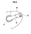
- the side outlets 15 and 16 are connected to a front side vent duct 31. This connection permits conditioned air A from the air conditioning unit 7 to be distributed toward the driver's seat and the passenger seat.
- the side outlets 15 and 16 and the front side vent duct 31 are connected to each other by inserting the end of the front side vent duct 31 into the side beams 3 and 4 from the side outlets 15 and 16 and mounting a joint duct 32 on the side outlets 15 and 16.
- the joint duct 32 is connected to a side vent grill 33 of the instrument panel 30. This connection permits the conditioned air from the air conditioning unit 7 to blow out from a side vent grill 33.
- the tube dimensions of the side outlet 15 and 16 portions or second portions in the side beams 3 and 4 are greater than tube dimensions of the airflow passage 13 and 14 portions or first portions located upstream of the side outlet 15 and 16 portions. Therefore, the side outlet 15 and 16 portions have enlarged tube portions 19 and 20 as second portions having larger tube dimensions. Formation of the enlarged tube portions 19 and 20 to the side outlet 15 and 16 portions in this manner reduces opening ratios of the side outlets 15 and 16 in the side beams 3 and 4.
- This structure enhances the strength of the side beams 3 and 4, i.e., strength of the cross car beam 1, ensuring the opening areas of the side outlets 15 and 16.
- the cross car beam 1 is not required to increase in thickness for improvement in the strength, and thus the cross car beam 1 does not increase in weight, being suitably used in a vehicle.
- the duct member is inserted in the cross car beam 1.
- the duct member forms a passage for the conditioned air A from the air conditioning u nit 7 in the cross car beam 1.
- the duct member includes an airflow duct 22 to be inserted into the center block 2.
- the duct member includes branch ducts 23 and 24 that are inserted into the side beams 3 and 4, respectively.
- the airflow duct 22 has a shape similar to that of the center block 2. That is, the airflow duct 22 includes a cylindrical portion 22a corresponding to the center member 2a of the center block 2.
- the airflow duct 22 includes cylindrical connecting portions 22b and 22c corresponding to the side members 2b and 2c.
- the cylindrical portion 22a and the connecting portions 22b and 22c are integrally formed.
- the connecting portions 22b and 22c are provided, at their ends closer to inlets, with inlets 22f and 22g facing the inlets 8 and 9.
- the connecting portions 22b and 22c are provided, at their ends closer to outlets, with fitting openings 22d and 22e corresponding to the connecting openings 10 and 11 of the side members 2b and 2c.
- the fitting openings 22d and 22e are open toward the side outlets 15 and 16 in the connecting portions 22b and 22c.
- the later-described ends of the branch ducts 23 and 24 closer to inlets are inserted and fitted into the fitting openings 22d and 22e.
- the branch ducts 23 and 24 are inserted into the side beams 3 and 4, respectively. As illustrated in Figs. 8 and 10, the branch ducts 23 and 24 have cylindrical shapes having outer dimensions substantially identical to the inner dimensions of the airflow passages 13 and 14 portions of the side beams 3 and 4. The branch ducts 23 and 24 have lengths substantially identical to those of the side beams 3 and 4, respectively.
- the branch ducts 23 and 24 have portions corresponding to the side outlets 15 and 16. These portions are bent perpendicularly toward the side outlets 15 and 16, and serve as bent portions 23a and 24a.
- the ends of the bent portions 23a and 24a, i.e., ends closer to the outlet have outlets 23c and 24c facing the outlets 15 and 16.
- the outlets 23c and 24c abut against the side outlets 15 and 16, and the branch ducts 23 and 24 introduce the conditioned air A to the side outlets 15 and 16.
- the ends of the branch ducts 23 and 24 opposite from the bent portions 23a and 24a, i.e., ends closer to the inlet have connecting openings 23d and 24d.
- the connecting openings 23d and 24d are fitted to the fitting openings 22d and 22e of the connecting portions 22b and 22c, and the airflow duct 22 and the branch ducts 23 and 24 connect to and communicate with each other.
- starting ends of the bent portions 23a and 24a include curved portions 23b and 24b.
- the curved portions 23b and 24b are curved in a direction separating away from the respective side outlets 15 and 16.
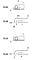
- conditioned air A from the air conditioning unit 7 temporarily pools at the curved portions 23b and 24b as illustrated in Figs. 4A and 4B.
- the pooled and conditioned air A then flows along the bent portions 23a and 24a and is blown out from the side outlets 15 and 16.
- the conditioned air A is controlled to blow out from the side outlets 15 and 16 along the substantially right-angled bent portions 23a and 24a, thus ensuring straight blowing of the conditioned air A.
- conditioned air from the side vent is reliably sent toward the driver's seat or the passenger seat, achieving efficient air conditioning operation.
- the side outlets 15 and 16 port-ions are enlarged in tube dimension, allowing the curved portions 23b and 24b to be smoothly inserted into the side outlets 15 and 16.
- Figs. 5A and 5B illustrate a flow of conditioned air in the bent portions 23a and 24a if the curved portions 23b and 24b are not provided. This structure does not ensure straight blowing of the conditioned air.
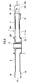
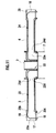
- Figs. 6 to 11 illustrate steps for assembling the airflow duct 22 and the branch ducts 23 and 24 into the cross car beam 1.
- the cylindrical portion 22a and the connecting portions 22b and 22c are set such that the cylindrical portion 22a faces the center member 2a, and the connecting portions 22b and 22c face the side members 2b and 2c.
- the airflow duct 22 is inserted into the center block 2.
- the fitting openings 22d and 22e of the airflow duct 22 are located at positions coinciding with the connecting openings 10 and 11 of the center block 2.
- Figs. 8 and 9 illustrate a step of inserting the branch duct 24 into the side beam 4.
- Figs. 10 and 11 illustrate a subsequent step of inserting the branch duct 23 into the side beam 3.
- the branch ducts 23 and 24 are inserted into the side beams 3 and 4 from the sides of the connecting openings 23d and 24d.
- the branch ducts 23 and 24 are inserted into the side beams 3 and 4 until the bent portions 23a and 24a abut against the corresponding side outlets 15 and 16 after they are inserted from the open ends 17 and 18 of the side beams 3 and 4.
- the side outlets 15 and 16 portions are formed with the enlarged tube portions 19 and 20 and their tube dimensions are increased.
- the bent portions 23a and 24a are smoothly inserted until they abut against the side outlets 15 and 16.
- the branch ducts 23 and 24 permit the connecting openings 23d and 24d that are ends on the insertion side to be fitted into the fitting openings 22d and 22e of the airflow duct 22 already inserted into the center block 2.
- the insides of the connecting portions 22b and 22c of the airflow duct 22 and the insides of the branch ducts 23 and 24 are brought into communication with each other.
- the airflow duct 22 and the branch ducts 23 and 24 function as passages of the conditioned air A from the air conditioning unit 7, introducing the conditioned air A from the air conditioning unit 7 into the side outlets 15 and 16, allowing the conditioned air A to be blown out from the outlets 15 and 16.
- the passage of the conditioned air A has a double structure including an outer side center block 2 and side beams 3 and 4, and an inner side airflow duct 22 and branch ducts 23 and 24.
- This double structure achieves the passage free from leakage of conditioned air A. Even if the double structure is complicated, the assembling operation is carried out by inserting the airflow duct 22 into the center block 2 and by inserting the branch ducts 23 and 24 into the side beams 3 and 4. This method achieves a simple assembling and enhances the assembling workability.
- the branch ducts 23 and 24 may be inserted into the side beams 3 and 4 such that the branch duct 23 is first inserted into the side beam 3 and then, the branch duct 24 is inserted into the side beam 4.
- a cross car beam 40 also includes the substantially central center block 2, and the side beams 3 and 4 extending from the left and right ends of the center block 2 in the widthwise direction of the vehicle.
- the center block 2 has the duct member inserted therein.
- the duct member includes the airflow duct 22 and the branch ducts 23 and 24.
- the airflow duct 22 is inserted into the center block 2, the branch ducts 23 and 24 are inserted into the side beams 3 and 4, and the duct member is assembled to the cross car beam 40.
- This assembling operation may be carried out in the same manner as that of the first embodiment.
- the passage of the conditioned air is of the double structure, and the members are simply be assembled.
- the airflow duct 22 is inserted into the center block 2 from the inlets 8 and 9.
- the branch ducts 23 and 24 are inserted into the side beams 3 and 4.
- the connecting openings 23d and 24d are fitted into the fitting openings 22d and 22e of the airflow duct 22, and the airflow duct 22 and the branch ducts 23 and 24 are connected to each other.
- the passage of the conditioned air having the double structure simplifies assembling of the duct member including the airflow duct 22 and the branch ducts 23 and 24 into the cross car beam.
- the side beams 3 and 4 have the side outlets 15 and 16 on the side of the open ends 17 and 18.
- the tube dimensions of the outlets 15 and 16 portions or enlarged tube portions 19 and 20 are greater than those of the airflow passage 13 and 14 portions. This structure ensures the strength of the cross car beam 40 without increasing the thickness, and restrains the weight of the cross car beam 40 from increasing.
- the open ends 17 and 18 in the side beams 3 and 4 serve as rear outlets.
- the open ends 17 and 18 as the rear outlets are connected to the rear ducts 43 and 44 as illustrated in Figs. 12 and 14.
- the ends of the branch ducts 23 and 24 to be inserted into the side beams 3 and 4 on the side of the side outlets 15 and 16 are open as rear connecting openings 45 and 46.
- the branch ducts 23 and 24 are inserted in the side beams 3 and 4 such that the rear connecting openings 45 and 46 are aligned with the open ends 17 and 18 of the side beams 3 and 4.
- the ends of the rear ducts 43 and 44 are respectively inserted and fitted between the rear connecting openings 45 and 46 and the open ends 17 and 18. With this arrangement, conditioned air A from the air conditioning unit 7 is introduced into the rear ducts 43 and 44 from the open ends 17 and 18 of the side beams 3 and 4, and is blown out from the rear ducts 43 and 44 toward the rear seat side.
- the open ends 17 and 18 of the side beams 3 and 4 and the rear ducts 43 and 44 are connected to each other using joint ducts 47.
- the joint duct 47 connects the open ends 17 and 18 and the rear ducts 43 and 44 with each other, with the joint duct 47 disposed in a side pillar 48 of the vehicle body.
- the rear ducts 43 and 44 extend downward along the mounting bracket 5 (see Fig. 12).
- the side outlets 15 and 16 and the open ends 17 and 18 as the rear outlets have doors 51 and 52 or louvers for switching the conditioned air A therebetween.
- the doors 51 and 52 are rotatably disposed in the enlarged tube portions 19 and 20 in the side beams 3 and 4. The doors 51 and 52 are rotated to switch between the side outlets 15 and 16 and the open ends 17 and 18.
- the doors 51 and 52 are disposed in corresponding portions between the enlarged tube portions 19 and 20 in the branch ducts 23 and 24 inserted into the side beams 3 and 4.
- the door 51 is curved from the open ends 17 and 18 toward the airflow passages 13 and 14. This curved shape guides the conditioned air A to smoothly flow into the side outlets 15 and 16, thus reliably supplying conditioned air A to the side outlets 15 and 16.
- the doors 51 and 52 provided in the enlarged tube portions 19 and 20 do not narrow the airflow passage, thus to open or close the airflow passage without deteriorating the airflow supply resistance.
Landscapes
- Engineering & Computer Science (AREA)
- Mechanical Engineering (AREA)
- Physics & Mathematics (AREA)
- Thermal Sciences (AREA)
- Chemical & Material Sciences (AREA)
- Combustion & Propulsion (AREA)
- Transportation (AREA)
- Air-Conditioning For Vehicles (AREA)
Abstract
Description
- This application is based upon and claims the benefit of priority from Japanese Patent Applications No. 2005-018493 and No. 2005-018501 each filed on January 16, 2005; the entire contents of which are incorporated herein by reference.
- The invention relates to an airflow distribution structure of a vehicular air conditioning system, and more particularly, to an airflow distribution structure for distributing conditioned air into the passenger room using a cross car beam.
- A cross car beam is positioned proximate to the boundary between an engine room and a passenger room in an automobile such that the cross car beam extends across a vehicle body. The cross car beam extends between both side surfaces of the vehicle body, and the opposite ends of the cross car beam are connected to the opposite inner side surfaces of the vehicle body. This structure reinforces rigidity of the vehicle body in the transverse direction, and receives an impact applied at the time of side collision. The document, Japanese Patent Application Publication Laid-open No. H10-44762, describes a structure in which such a cross car beam is used as a duct of conditioned air from an air conditioning unit.
- With reference to Fig. 15, the
cross car beam 100 extends between bothside walls 111. In this extending state, both ends of the cross car beam are fixed to bothside walls 111 of the vehicle by bolts, welding, or the like and thecross car beam 100 stretches across thevehicle body 110 in the transverse direction. Thecross car beam 100 reinforces the rigidity of thevehicle body 110 in the transverse direction. In addition, a shaft of asteering wheel 112 and an airbag are set in the vehicle body using thecross car beam 100. - The
cross car beam 100 has a hollow tube. The intermediate portion of the hollow tube is connected to a duct extending from a vehicular air conditioning unit (not illustrated) to introduce conditioned air from the air conditioning unit. The surface of thecross car beam 100 closer to the passenger room includes a plurality ofoutlets 120 for adjusting the temperature of air sent to a passenger on a driver's seat or on a passenger seat. Conditioned air from the air conditioning unit is blown out from theoutlets 120. - According to this structure, the tubular
cross car beam 100 has the outlets for blowing out conditioned air, and the strength of thecross car beam 100 is deteriorated. Thus, thecross car beam 100 does not sufficiently reinforce the rigidity of the vehicle body in the transverse direction that is an original purpose of the cross car beam. If the thickness of the cross car beam is increased to enhance the strength, the cross car beam increases in weight, being not suitable for use in a vehicle. - In this structure, the
cross car beam 100 includes a hollow tube, and theoutlets 120 are provided in the hollow tube to blow conditioned air. This structure is difficult to control the blowing direction of the conditioned air. To control the conditioned air, it is necessary to optimally set conditions such as opening positions and opening angles of the outlets. Such setting causes a complicated structure, so that the manufacture of the cross car beam is troublesome, difficult, and impractical. - Accordingly, a duct member for controlling the conditioned air is incorporated in the cross car beam. This structure, however, causes a complicated operation for assembling the duct member into the cross car beam and an operation for making the duct member as a passage for conditioned air, and increases the assembling steps.
- The first object of the invention is to provide an airflow distribution structure of a vehicular air conditioning system that sufficiently reinforces rigidity of a vehicle body in the transverse direction without deteriorating the strength even if a cross car beam is formed with outlets for conditioned air so that the cross car beam is used as a duct for conditioned air from an air conditioning system.
- The second object of the invention is to provide an airflow distribution structure of a vehicular air conditioning system in which, if a cross car beam is used as a duct for conditioned air, a duct member for controlling the blowing out of conditioned air is simply incorporated in the cross car beam, and the operability thereof is enhanced.
- An aspect of the invention provides the following airflow distribution structure of a vehicular air conditioning system. The airflow distribution structure includes a tubular strength member (1; 40) extending behind an instrument panel (30) in a width direction of a vehicle and having both ends fixed to opposite side walls inside a passenger room, respectively. The strength member includes a first portion (13; 14) having an airflow passage (13; 14) therein. The strength member includes a second portion (19; 20) having a first outlet (15; 16) communicating with the airflow passage. The second portion (19; 20) is enlarged to be greater in tube dimension than the first portion (13; 14).
- The airflow distribution structure further includes a duct member (22; 23; 24) inside the strength member (1; 40), having the airflow passage (13; 14) therein and communicating with the first outlet (15; 16). The duct member includes a curved portion coinciding with the first outlet, the curved portion (23b; 24b) curving away from the first outlet to curve close to the first outlet.
- The first outlet includes first outlets (15; 16; 17; 18) in a longitudinal direction of the strength member. The second portion includes therein louvers (51; 52) switchable between the first outlets.
- The strength member (1; 40) has a first inlet (8; 9) communicating with the airflow passage (13; 14). The strength member has an end opening (17; 18) at the end thereof. The airflow distribution structure includes an airflow distribution duct having a second inlet (22f; 22g) facing the first inlet. The airflow distribution structure includes a fitting opening (22d; 22e) closer to outlet. The airflow distribution structure includes a branch duct (23; 24) having a connecting opening (23d; 24d) closer to inlet and fittable with the fitting opening; and a second outlet (23c; 24c) facing the first outlet (15; 16). The airflow distribution duct (22) is inserted into the strength member (1; 40) from the first outlet (8; 9). The branch duct (23; 24) is inserted into the strength member (1; 40) from the end opening (17; 18). The fitting opening (22d; 22e) and the connecting opening (23d; 24d) are fitted and communicate with each other.
- According to the airflow distribution structure, the tubular strength member defines an airflow passage and an outlet for conditioned airflow from an air conditioning unit, being used as a duct for conditioned airflow from an air conditioner.
- The second portion is greater in tube dimension than the first portion. This structure enhances the strength of the strength member, ensuring opening area of the first outlet. Thus, the strength member is not required to increase in thickness, being suited for mounting on a vehicle.
- The airflow distribution duct and the branch duct are inserted in the tubular strength member, allowing for smooth control of conditioned airflow.
- The strength member is formed with a passage for conditioned airflow by inserting the airflow duct and the branch duct into the strength member and by fitting and connecting the fitting connecting opening of the airflow distribution duct and the connecting opening of the branch duct with each other. This achieves a simple assembling operation and enhances the operability
-
- Fig. 1 is a perspective view of a cross car beam according to a first embodiment;
- Fig. 2 is a cross section of the cross car beam illustrated in Fig. 1;
- Fig. 3 is a cross section illustrating a connecting structure of the cross car beam and a side vent duct;
- Figs. 4A and 4B are respectively a front view and a cross section of an enlarged pipe portion illustrated in Fig. 1;
- Figs. 5A and 5B are respectively a front view and a cross section of a cross car beam having no enlarged pipe portion;
- Fig. 6 is a cross section of an airflow duct and the cross car beam before the airflow duct is inserted;
- Fig. 7 is a cross section of the cross car beam in which the airflow duct is inserted;
- Fig. 8 is a cross section of a side beam in which one of branch ducts is inserted;
- Fig. 9 is a cross section of the side beam in which one of the branch ducts is inserted;
- Fig. 10 is a cross section of the side beam in which the other branch duct is inserted;
- Fig. 11 is a cross section of the side beam in which the other branch duct is inserted;
- Fig. 12 is a perspective view of a cross car beam according to a second embodiment;
- Fig. 13 is a cross section of the cross car beam illustrated in Fig. 12;
- Fig. 14 is a perspective view illustrating a connecting structure between a rear duct and the cross car beam illustrated in Fig. 12; and
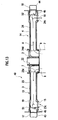
- Fig. 15 is perspective view of a related airflow distribution structure.
- The invention will be specifically described according to illustrated embodiments below. In the embodiments, like parts are designated with like reference numerals.
- As illustrated in Fig. 1, a cross car beam 1 as a strength member extends in the widthwise direction of a vehicle. The cross car beam 1 includes a
center block 2 at the longitudinally central portion. The cross car beam 1 includes a pair ofside beams center block 2. The entire cross car beam 1 is made of metal. - The cross car beam 1 is disposed behind an instrument panel 30 (see Fig. 3) provided in the front side of a passenger room, and extends in the widthwise direction of the vehicle body. The cross car beam 1 includes mounting
brackets 5 at the longitudinally opposite ends (extended ends of the side beams 3 and 4). The mountingbrackets 5 are fixed to the opposite side walls of the vehicle body by screws or the like. With this configuration, the cross car beam 1 reinforces the rigidity of the vehicle body in the transverse direction. This layout is also used for mounting the cross car beam 1 on a steering shaft or an airbag (not illustrated). - As illustrated in Fig. 2, the cross car beam 1 is formed by integrally joining hollow pipes by welding or the like. With this arrangement, the entire cross car beam 1 has the hollow pipes. The cross car beam 1 includes the
center block 2 at the central portion. Thecenter block 2 includes a hollowcenter pipe member 2a through thecenter block 2 in the vertical direction. Thecenter block 2 is integrally provided at the opposite sides withside members side members - An
air conditioning unit 7 that conditions the air inside a vehicle is disposed behind the instrument panel, coinciding with thecenter block 2, and supplies conditioned air A to thecenter block 2. - The
side members center block 2 is opened at the ends proximate to theair conditioning unit 7, forminginlets air conditioning unit 7 is introduced. Theside members openings center block 2, with the side beams 3 and 4 facing the connectingopenings side members airflow passages air conditioning unit 7 flows. - The hollow
center pipe member 2a in thecenter block 2 permits conditioned air A from theair conditioning unit 7 to be introduced into thecenter member 2a. Thecenter member 2a is connected to a defroster duct (not illustrated), and conditioned air A introduced into thecenter member 2a is blown out toward the lower side of a front panel of the vehicle body through the defroster duct. - The side beams 3 and 4 have extended ends, as open ends 17 and 18, in the longitudinal direction. The side beams 3 and 4 have side surfaces that are adjacent to the open ends 17 and 18. The side surfaces of the open ends 17 and 18 have
side outlets side outlets duct 31. This connection permits conditioned air A from theair conditioning unit 7 to be distributed toward the driver's seat and the passenger seat. - The
side outlets duct 31 are connected to each other by inserting the end of the front side ventduct 31 into the side beams 3 and 4 from theside outlets joint duct 32 on theside outlets joint duct 32 is connected to aside vent grill 33 of theinstrument panel 30. This connection permits the conditioned air from theair conditioning unit 7 to blow out from aside vent grill 33. - In this embodiment, the tube dimensions of the
side outlet airflow passage side outlet side outlet tube portions enlarged tube portions side outlet side outlets side outlets - In this embodiment, the duct member is inserted in the cross car beam 1. The duct member forms a passage for the conditioned air A from the air
conditioning u nit 7 in the cross car beam 1. As illustrated in Fig. 6, the duct member includes anairflow duct 22 to be inserted into thecenter block 2. The duct member includesbranch ducts - The
airflow duct 22 has a shape similar to that of thecenter block 2. That is, theairflow duct 22 includes acylindrical portion 22a corresponding to thecenter member 2a of thecenter block 2. Theairflow duct 22 includes cylindrical connectingportions side members cylindrical portion 22a and the connectingportions portions inlets inlets portions fitting openings openings side members fitting openings side outlets portions branch ducts fitting openings - The
branch ducts branch ducts airflow passages branch ducts - The
branch ducts side outlets side outlets bent portions bent portions outlets outlets outlets side outlets branch ducts side outlets branch ducts bent portions openings openings fitting openings portions airflow duct 22 and thebranch ducts - As illustrated in Figs. 8 and 10, starting ends of the
bent portions curved portions curved portions respective side outlets curved portions respective side outlets air conditioning unit 7 temporarily pools at thecurved portions bent portions side outlets - By forming the
curved portions bent portions side outlets bent portions side outlets curved portions side outlets - Figs. 5A and 5B illustrate a flow of conditioned air in the
bent portions curved portions - Figs. 6 to 11 illustrate steps for assembling the
airflow duct 22 and thebranch ducts cylindrical portion 22a and the connectingportions cylindrical portion 22a faces thecenter member 2a, and the connectingportions side members airflow duct 22 is inserted into thecenter block 2. By inserting theairflow duct 22, thefitting openings airflow duct 22 are located at positions coinciding with the connectingopenings center block 2. - Next, the
branch ducts corresponding side beams branch duct 24 into theside beam 4. Figs. 10 and 11 illustrate a subsequent step of inserting thebranch duct 23 into theside beam 3. - The
branch ducts openings branch ducts bent portions corresponding side outlets side outlets enlarged tube portions bent portions side outlets - With this insertion, the
branch ducts openings fitting openings airflow duct 22 already inserted into thecenter block 2. With this fitting, the insides of the connectingportions airflow duct 22 and the insides of thebranch ducts airflow duct 22 and thebranch ducts air conditioning unit 7, introducing the conditioned air A from theair conditioning unit 7 into theside outlets outlets - In this assembling operation, the passage of the conditioned air A has a double structure including an outer
side center block 2 andside beams side airflow duct 22 andbranch ducts airflow duct 22 into thecenter block 2 and by inserting thebranch ducts - The
branch ducts branch duct 23 is first inserted into theside beam 3 and then, thebranch duct 24 is inserted into theside beam 4. - With reference to Figs. 12 to 14, a
cross car beam 40 according to a second embodiment also includes the substantiallycentral center block 2, and the side beams 3 and 4 extending from the left and right ends of thecenter block 2 in the widthwise direction of the vehicle. Like the first embodiment, thecenter block 2 has the duct member inserted therein. The duct member includes theairflow duct 22 and thebranch ducts airflow duct 22 is inserted into thecenter block 2, thebranch ducts cross car beam 40. This assembling operation may be carried out in the same manner as that of the first embodiment. Thus, in this embodiment also, the passage of the conditioned air is of the double structure, and the members are simply be assembled. - That is, the
airflow duct 22 is inserted into thecenter block 2 from theinlets branch ducts openings fitting openings airflow duct 22, and theairflow duct 22 and thebranch ducts airflow duct 22 and thebranch ducts - The side beams 3 and 4 have the
side outlets outlets enlarged tube portions airflow passage cross car beam 40 without increasing the thickness, and restrains the weight of thecross car beam 40 from increasing. - In this embodiment, the open ends 17 and 18 in the side beams 3 and 4 serve as rear outlets. The open ends 17 and 18 as the rear outlets are connected to the
rear ducts branch ducts side outlets openings branch ducts rear connecting openings rear ducts openings air conditioning unit 7 is introduced into therear ducts rear ducts - In Fig. 13, the open ends 17 and 18 of the side beams 3 and 4 and the
rear ducts joint ducts 47. Thejoint duct 47 connects the open ends 17 and 18 and therear ducts joint duct 47 disposed in aside pillar 48 of the vehicle body. Therear ducts - In this embodiment, as illustrated in Fig. 13, the
side outlets doors doors enlarged tube portions doors side outlets - The
doors enlarged tube portions branch ducts door 51 is curved from the open ends 17 and 18 toward theairflow passages side outlets side outlets doors enlarged tube portions - Although the invention has been described above by reference to certain embodiments of the invention, the invention is not limited to the embodiments described above. Modifications and variations of the embodiments described above will occur to those skilled in the art, in light of the above teachings. The scope of the invention is defined with reference to the following claims.
Claims (4)
- An airflow distribution structure of a vehicular air conditioning system, comprising:a tubular strength member extending behind an instrument panel in a width direction of a vehicle and having both ends fixed to opposite side walls inside a passenger room, respectively,wherein the strength member comprises:a first portion having an airflow passage therein; anda second portion having a first outlet communicating with the airflow passage,wherein the second portion is enlarged to be greater in tube dimension than the first portion.
- The airflow distribution structure according to claim 1, further comprising:a duct member inside the strength member, having the airflow passage therein and communicating with the first outlet,wherein the duct member comprises a curved portion coinciding with the first outlet, the curved portion curving away from the first outlet to curve close to the first outlet.
- The airflow distribution structure according to claim 1,
wherein the first outlet comprises first outlets in a longitudinal direction of the strength member,
wherein the second portion comprises therein louvers switchable between the first outlets. - The airflow distribution structure according to claim 1,
wherein the strength member has a first inlet communicating with the airflow passage,
wherein the strength member has an end opening at the end thereof,
the airflow distribution structure further comprises:an airflow distribution duct having a second inlet facing the first inlet; and a fitting opening closer to outlet; anda branch duct having a connecting opening closer to inlet and fittable with the fitting opening; and a second outlet facing the first outlet,wherein the airflow distribution duct is inserted into the strength member from the first outlet,wherein the branch duct is inserted into the strength member from the end opening,wherein the fitting opening and the connecting opening are fitted and communicate with each other.
Applications Claiming Priority (2)
| Application Number | Priority Date | Filing Date | Title |
|---|---|---|---|
| JP2005018493A JP2006205826A (en) | 2005-01-26 | 2005-01-26 | Air distribution structure of air conditioner for vehicle |
| JP2005018501A JP2006205828A (en) | 2005-01-26 | 2005-01-26 | Air distribution structure of air conditioner for vehicle |
Publications (2)
| Publication Number | Publication Date |
|---|---|
| EP1685989A2 true EP1685989A2 (en) | 2006-08-02 |
| EP1685989A3 EP1685989A3 (en) | 2007-05-02 |
Family
ID=36272174
Family Applications (1)
| Application Number | Title | Priority Date | Filing Date |
|---|---|---|---|
| EP06000073A Withdrawn EP1685989A3 (en) | 2005-01-26 | 2006-01-03 | Airflow distribution structure of vehicular air conditioning system |
Country Status (2)
| Country | Link |
|---|---|
| US (1) | US20060199492A1 (en) |
| EP (1) | EP1685989A3 (en) |
Cited By (3)
| Publication number | Priority date | Publication date | Assignee | Title |
|---|---|---|---|---|
| FR2925010A1 (en) * | 2007-12-14 | 2009-06-19 | Faurecia Interieur Ind Snc | DASHBOARD TRAVERSE FOR MOTOR VEHICLE AND VEHICLE COMPRISING SUCH A TRAVERSE |
| CN107031847A (en) * | 2015-11-24 | 2017-08-11 | 哈米尔顿森德斯特兰德公司 | Cabin supply line |
| US20240253708A1 (en) * | 2021-05-17 | 2024-08-01 | Atieva, Inc. | Air duct integration into cross-car beam structure |
Families Citing this family (9)
| Publication number | Priority date | Publication date | Assignee | Title |
|---|---|---|---|---|
| FR2890029B1 (en) * | 2005-08-31 | 2007-11-30 | Faurecia Interieur Ind Snc | AERAULIC TRAVERSE FOR MOTOR VEHICLE |
| US7503622B2 (en) * | 2006-08-25 | 2009-03-17 | Gm Global Technology Operations, Inc. | Tubular instrument panel support structure |
| DE102009058996B4 (en) * | 2008-12-21 | 2012-12-06 | W.E.T. Automotive Systems Ag | aerator |
| US20140103685A1 (en) * | 2011-02-23 | 2014-04-17 | Ayyakannu Mani | Lightweight Cross-Car Beam and Method of Construction |
| WO2014184891A1 (en) * | 2013-05-15 | 2014-11-20 | 株式会社小松製作所 | Cab, and work vehicle |
| JP5770912B1 (en) * | 2014-11-18 | 2015-08-26 | 株式会社ヴァレオジャパン | Air conditioner for vehicles |
| US20180200940A1 (en) * | 2017-01-13 | 2018-07-19 | Nihon Plast Co., Ltd. | Hollow mold |
| EP3508399B1 (en) * | 2018-01-09 | 2023-02-22 | Motherson Innovations Company Limited | Self-supporting carrier structure for an instrument panel in a vehicle, instrument panel comprising such a carrier structure and vehicle with such an instrument panel |
| CN115158488B (en) * | 2022-06-27 | 2023-11-14 | 重庆长安汽车股份有限公司 | Seat mounting beam assembly integrated with ventilating duct and automobile |
Citations (1)
| Publication number | Priority date | Publication date | Assignee | Title |
|---|---|---|---|---|
| JPH1044762A (en) | 1996-08-01 | 1998-02-17 | Inoac Corp | Passenger car having reinforce bar |
Family Cites Families (8)
| Publication number | Priority date | Publication date | Assignee | Title |
|---|---|---|---|---|
| JPS5516747Y2 (en) * | 1977-04-01 | 1980-04-18 | ||
| FR2789043B1 (en) * | 1999-01-29 | 2001-06-08 | Valeo Climatisation | TRANSVERSE BEAM FOR SUPPORTING A MOTOR VEHICLE DASHBOARD WITH INTEGRATED AIR DUCT |
| DE29916467U1 (en) * | 1999-09-18 | 1999-12-09 | Benteler Ag, 33104 Paderborn | Instrument holder |
| FR2799412B1 (en) * | 1999-10-06 | 2002-07-12 | Valeo Climatisation | HEATING AND / OR AIR CONDITIONING SYSTEM HAVING AN AIR DISTRIBUTION SYSTEM IN THE INTERIOR OF A MOTOR VEHICLE |
| CN1248877C (en) * | 2001-12-11 | 2006-04-05 | 株式会社电装 | Car air conditioner with rotary damper |
| US6739968B1 (en) * | 2002-11-08 | 2004-05-25 | Collins & Aikman Products Co. | Interchangeable air vent assembly and vehicles incorporating same |
| US6988764B2 (en) * | 2003-01-28 | 2006-01-24 | Calsonic Kansei Corporation | Cross car beam for vehicle |
| JP2004345363A (en) * | 2003-03-18 | 2004-12-09 | Calsonic Kansei Corp | Air duct for vehicle |
-
2006
- 2006-01-03 EP EP06000073A patent/EP1685989A3/en not_active Withdrawn
- 2006-01-17 US US11/332,399 patent/US20060199492A1/en not_active Abandoned
Patent Citations (1)
| Publication number | Priority date | Publication date | Assignee | Title |
|---|---|---|---|---|
| JPH1044762A (en) | 1996-08-01 | 1998-02-17 | Inoac Corp | Passenger car having reinforce bar |
Cited By (4)
| Publication number | Priority date | Publication date | Assignee | Title |
|---|---|---|---|---|
| FR2925010A1 (en) * | 2007-12-14 | 2009-06-19 | Faurecia Interieur Ind Snc | DASHBOARD TRAVERSE FOR MOTOR VEHICLE AND VEHICLE COMPRISING SUCH A TRAVERSE |
| WO2009077702A1 (en) * | 2007-12-14 | 2009-06-25 | Faurecia Interieur Industrie | Crossbar for dashboard of an automobile and automobile including such crossbar |
| CN107031847A (en) * | 2015-11-24 | 2017-08-11 | 哈米尔顿森德斯特兰德公司 | Cabin supply line |
| US20240253708A1 (en) * | 2021-05-17 | 2024-08-01 | Atieva, Inc. | Air duct integration into cross-car beam structure |
Also Published As
| Publication number | Publication date |
|---|---|
| EP1685989A3 (en) | 2007-05-02 |
| US20060199492A1 (en) | 2006-09-07 |
Similar Documents
| Publication | Publication Date | Title |
|---|---|---|
| EP1685989A2 (en) | Airflow distribution structure of vehicular air conditioning system | |
| US5934744A (en) | Cross car structural beam | |
| US8641489B2 (en) | Air conditioning device for a vehicle comprising a network of de-icing ducts | |
| US6629424B1 (en) | Air conditioner for car and instrument panel module | |
| US20100178861A1 (en) | Vehicular air conditioner | |
| US11390139B2 (en) | Vehicle air conditioning device | |
| US5113748A (en) | Defroster construction for automotive air conditioner | |
| US5890651A (en) | Air conditioning apparatus for vehicle | |
| US8795042B2 (en) | Defroster nozzle | |
| US20070128997A1 (en) | Vehicle air duct structure | |
| KR100729312B1 (en) | Blast duct for vehicle | |
| JP5831738B2 (en) | Ventilation structure of vehicle | |
| JP2006205828A (en) | Air distribution structure of air conditioner for vehicle | |
| US20080309113A1 (en) | Motor Vehicle Dashboard Cross-Member, an Assembly Including Such a Cross-Member, and Method of Fabricating Such a Cross-Member | |
| JP7586719B2 (en) | Wind direction adjustment device | |
| JP2006205826A (en) | Air distribution structure of air conditioner for vehicle | |
| US20020101093A1 (en) | Dashboard designed to be mounted in an interior of a vehicle, as well as to a vehicle body equipped with such a dashboard | |
| JP4096243B2 (en) | Ventilation duct | |
| JP4382549B2 (en) | Vehicle defroster device | |
| JP4209695B2 (en) | VEHICLE AIR CONDITIONING UNIT AND VEHICLE AIR CONDITIONER | |
| JP3710004B2 (en) | Duct structure for vehicle air conditioning | |
| CN222819876U (en) | Air supply assembly, vehicle body frame and vehicle | |
| JP4487162B2 (en) | Vehicle air conditioner | |
| JP2003170729A (en) | Automotive air conditioners | |
| JP2002137622A (en) | Duct equipment |
Legal Events
| Date | Code | Title | Description |
|---|---|---|---|
| PUAI | Public reference made under article 153(3) epc to a published international application that has entered the european phase |
Free format text: ORIGINAL CODE: 0009012 |
|
| AK | Designated contracting states |
Kind code of ref document: A2 Designated state(s): AT BE BG CH CY CZ DE DK EE ES FI FR GB GR HU IE IS IT LI LT LU LV MC NL PL PT RO SE SI SK TR |
|
| AX | Request for extension of the european patent |
Extension state: AL BA HR MK YU |
|
| PUAL | Search report despatched |
Free format text: ORIGINAL CODE: 0009013 |
|
| AK | Designated contracting states |
Kind code of ref document: A3 Designated state(s): AT BE BG CH CY CZ DE DK EE ES FI FR GB GR HU IE IS IT LI LT LU LV MC NL PL PT RO SE SI SK TR |
|
| AX | Request for extension of the european patent |
Extension state: AL BA HR MK YU |
|
| RIC1 | Information provided on ipc code assigned before grant |
Ipc: B62D 25/14 20060101ALI20070328BHEP Ipc: B60H 1/00 20060101AFI20060517BHEP |
|
| 17P | Request for examination filed |
Effective date: 20070704 |
|
| 17Q | First examination report despatched |
Effective date: 20070924 |
|
| AKX | Designation fees paid |
Designated state(s): DE FR GB |
|
| STAA | Information on the status of an ep patent application or granted ep patent |
Free format text: STATUS: THE APPLICATION IS DEEMED TO BE WITHDRAWN |
|
| 18D | Application deemed to be withdrawn |
Effective date: 20090623 |