EP1685918B1 - Gewindeformer oder-bohrer - Google Patents
Gewindeformer oder-bohrer Download PDFInfo
- Publication number
- EP1685918B1 EP1685918B1 EP05000961A EP05000961A EP1685918B1 EP 1685918 B1 EP1685918 B1 EP 1685918B1 EP 05000961 A EP05000961 A EP 05000961A EP 05000961 A EP05000961 A EP 05000961A EP 1685918 B1 EP1685918 B1 EP 1685918B1
- Authority
- EP
- European Patent Office
- Prior art keywords
- shaft
- profile element
- attachment
- bore
- axial
- Prior art date
- Legal status (The legal status is an assumption and is not a legal conclusion. Google has not performed a legal analysis and makes no representation as to the accuracy of the status listed.)
- Expired - Lifetime
Links
- 238000005520 cutting process Methods 0.000 claims abstract description 3
- 239000000463 material Substances 0.000 claims description 19
- 238000000034 method Methods 0.000 claims description 5
- 230000000295 complement effect Effects 0.000 claims description 4
- 238000005245 sintering Methods 0.000 claims description 4
- 238000005476 soldering Methods 0.000 claims description 3
- 238000003466 welding Methods 0.000 claims description 3
- 229910000831 Steel Inorganic materials 0.000 claims description 2
- 239000007787 solid Substances 0.000 claims description 2
- 239000010959 steel Substances 0.000 claims description 2
- 230000004323 axial length Effects 0.000 claims 1
- 238000007373 indentation Methods 0.000 abstract 2
- 230000008878 coupling Effects 0.000 description 10
- 238000010168 coupling process Methods 0.000 description 10
- 238000005859 coupling reaction Methods 0.000 description 10
- 230000005540 biological transmission Effects 0.000 description 4
- 238000005336 cracking Methods 0.000 description 3
- 238000003754 machining Methods 0.000 description 3
- 238000004026 adhesive bonding Methods 0.000 description 2
- 230000015572 biosynthetic process Effects 0.000 description 2
- 239000002184 metal Substances 0.000 description 2
- 230000000694 effects Effects 0.000 description 1
Images
Classifications
-
- B—PERFORMING OPERATIONS; TRANSPORTING
- B23—MACHINE TOOLS; METAL-WORKING NOT OTHERWISE PROVIDED FOR
- B23G—THREAD CUTTING; WORKING OF SCREWS, BOLT HEADS, OR NUTS, IN CONJUNCTION THEREWITH
- B23G5/00—Thread-cutting tools; Die-heads
- B23G5/02—Thread-cutting tools; Die-heads without means for adjustment
- B23G5/06—Taps
-
- B—PERFORMING OPERATIONS; TRANSPORTING
- B23—MACHINE TOOLS; METAL-WORKING NOT OTHERWISE PROVIDED FOR
- B23G—THREAD CUTTING; WORKING OF SCREWS, BOLT HEADS, OR NUTS, IN CONJUNCTION THEREWITH
- B23G7/00—Forming thread by means of tools similar both in form and in manner of use to thread-cutting tools, but without removing any material
- B23G7/02—Tools for this purpose
-
- B—PERFORMING OPERATIONS; TRANSPORTING
- B23—MACHINE TOOLS; METAL-WORKING NOT OTHERWISE PROVIDED FOR
- B23B—TURNING; BORING
- B23B2228/00—Properties of materials of tools or workpieces, materials of tools or workpieces applied in a specific manner
- B23B2228/56—Two phase materials
-
- B—PERFORMING OPERATIONS; TRANSPORTING
- B23—MACHINE TOOLS; METAL-WORKING NOT OTHERWISE PROVIDED FOR
- B23G—THREAD CUTTING; WORKING OF SCREWS, BOLT HEADS, OR NUTS, IN CONJUNCTION THEREWITH
- B23G2200/00—Details of threading tools
- B23G2200/02—Tools in which the shank and the cutting part are made from different materials or from separate components
-
- B—PERFORMING OPERATIONS; TRANSPORTING
- B23—MACHINE TOOLS; METAL-WORKING NOT OTHERWISE PROVIDED FOR
- B23G—THREAD CUTTING; WORKING OF SCREWS, BOLT HEADS, OR NUTS, IN CONJUNCTION THEREWITH
- B23G2225/00—Materials of threading tools, workpieces or other structural elements
- B23G2225/28—Hard metal, i.e. cemented carbides
Definitions
- the invention relates to a thread former or drill according to the preamble of patent claim 1.
- a thread former or drill has become known in which a separate profile element is releasably attachable to a shaft.
- Shank and profile element have on the mutually facing sides projections and / or depressions which positively engage with each other so that an automatic centering of the profile element takes place on the shaft when both parts are axially clamped against each other. This is done by means of a screw which is guided through a hole in the profile element and screwed into an internally threaded bore of the shank.
- the shaft can be made in a conventional manner and with conventional dimensions of a high-strength material, in particular a suitable steel. He does not need to be thrown away when wearing the profile element.
- a provided plurality of different profile elements with different diameters, different pitch, etc. can be connected to a unit shaft.
- the profile element may consist of a suitable hard material. The material used for this is of course significantly lower than conventional tools.
- the recesses and the projections are provided, which engage in a form-fitting manner and at the same time cause a centering.
- the profile element is weakened by the hole for the fastening screw.
- very hard material such as carbide
- precise machining can be made.
- considerable forces arise in the region of the coupling sections in the transmission of the torque from the shaft to the profile element, which can lead to cracking in the case of a not particularly tough material.
- the screw is significantly loaded on train.
- a shank tool having an elongated shank axially pierced and having a chucking portion.
- a separate profile element of lesser length having a cutting profile section is provided at one end with a lug which is insertable into an enlarged bore portion of the facing shaft end.
- Profile member and lug are provided with a bore, and through the axial channel of the shaft extends a tie rod, which cooperates with the profile element to tighten the profile element firmly against the shaft. The torque is transmitted through the approach, for example, is out of round.
- the invention has for its object to overcome the disadvantages occurring in the known thread former or drill and to provide a thread former or drill, which has a dimensionally stable profile element.
- the profile element on the end facing the shaft has an axial projection which has an axial bore open towards the free end.
- the projections and / or recesses, which are otherwise provided on the side of the profile element facing the shaft, are now provided on the axial projection.
- the shank has an axial through bore, and the fastening device is axially fixable within the throughbore. Only the axial extension has a bore and the extension is made of a softer one and tougher material than the profile element and machinable.
- the fastening device interacts with the axial bore in the approach so that the parts can be axially clamped against each other.
- the profile element is completely solid, i. can be performed without a bore and therefore can absorb more forces without being overstressed, as may be the case with the conventional thread former or drill.
- the through hole near the neck on a shoulder may cooperate with the shoulder to exert an axial force upon actuation of the lug, through which the coupling portions of the neck and shaft are stretched against each other.
- a suitable fastener may, for example, a bayonet-like cooperate with the opening in the axial projection, wherein, for example ramp surfaces on the fastener cooperate with ramp surfaces of the approach to produce an axial tensile force upon rotation of the fastener.
- the approach may have an internally threaded bore for receiving a screw which is screwed from the through bore of the shaft forth.
- the head of such a fastening screw which cooperates with preferably a shoulder in the through hole, can be made arbitrarily long to accommodate high tensile forces.
- the underside of the head is provided with a conical portion which cooperates with a complementary conical portion of the shoulder.
- profile element and approach of the same material for example in the sintering process.
- a design is preferred such that profile element on the one hand and axial approach on the other hand consist of different materials.
- the approach can be formed of a tougher softer material, which avoids cracking in the coupling area and ensures better machining capability.
- the formation with two materials can e.g. be made by making a compact for a sintering process in two layers, one layer forms the profile element and the other forms the axial extension.
- separate parts may be formed of different materials, which are then joined together by a suitable bonding method, such as by welding, soldering, gluing or the like.
- WO 03/011508 Various means are described for achieving torque transfer across the separate parts at the same time centering, if they are clamped axially against each other.
- a particularly advantageous embodiment of the invention provides for this purpose to provide a planing or crown edge toothing.
- the self-centering coupling enables the transmission of maximum torques in the smallest space.
- the apexes of the teeth or their gaps in the longitudinal section are not at right angles to the axis, but inclined to the self-centering effect.
- crankshafts or transmission bridges such a coupling has become known per se.
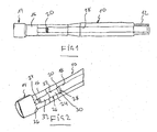
- a tool shank 10 which has a clamping portion 12 at one end and at the other end a coupling portion, not shown.
- a shaped profile element 14 is shown, which has a Anformkegel at the left end and at the periphery a thread profile, which is not shown. It is used to produce an internal thread according to the Gewindefurch- or -form vide.
- the circumference of the shape profile element 14 is polygonal, for example, which is likewise not recognizable.
- the shape profile element 14 consists for example of hard metal. At the left end adjoins the shape profile element 14 an axial cylindrical projection 16, which has a slightly smaller diameter than the shape profile element 14.
- the projection 16 also has a coupling portion.
- the coupling portions of shaft 10 and shoulder 16 may be formed, for example, in a manner as shown in FIG WO 03/011508 is shown.
- a toothing can be provided, for example, a crown edge toothing, which at the same time accomplishes a centering of the two parts.
- the shaft 10 has an axial through hole 18 which has an annular shoulder 20 near the left end facing the projection 16. After the conical annular shoulder, the throughbore narrows to a slightly smaller diameter bore portion 22. This bore portion receives a non-threaded shank portion 24 of a fastening screw 26 with a head 28.
- the head 28 has at the bottom a conical portion 30 which is complementary to the annular shoulder 20 cooperates.
- a threaded portion 32 of the screw 26 is screwed into a threaded bore 34 of the projection 16. Both through bore 18 and threaded bore 34 are axially and coaxially when clamping shaft 10 and mold member 14.
- the screw head 28 has a Phillips or the like for adjustment from the clamping end 12 ago. With the help of the screw 26, the parts 14, 16 and 10 are axially clamped against each other, the coupling portions ensure that an effective torque transmission is possible and accurate centering of these parts.
- the mold element 14 is made of very hard material, such as hard metal, which is known to be difficult to work and less tough.
- the material for approach 16 should be softer and tougher to prevent cracking while also providing better machining capability.
- the bipartite is in Fig. 2 indicated by the dashed line 36.
- the parts 14, 16 can be produced in the sintering process by producing a two-layered compact. Alternatively, the parts 14, 16 can be manufactured separately and then joined together by welding, gluing or soldering.
Landscapes
- Engineering & Computer Science (AREA)
- Mechanical Engineering (AREA)
- Artificial Filaments (AREA)
- Dowels (AREA)
- Insertion Pins And Rivets (AREA)
- Drilling Tools (AREA)
- Powder Metallurgy (AREA)
- Earth Drilling (AREA)
Description
- Die Erfindung bezieht sich auf einen Gewindeformer oder -bohrer nach dem Oberbegriff des Patentanspruchs 1.
- Aus
WO 03/011508 - Bei dem bekannten Werkzeug kann der Schaft in herkömmlicher Weise und mit herkömmlichen Abmessungen aus einem hoch belastbaren Material, insbesondere einem geeigneten Stahl, gefertigt werden. Er braucht bei Verschleiß des Profilelements nicht fortgeworfen zu werden. Dadurch kann eine bereitgestellte Mehrzahl unterschiedlicher Profilelemente mit unterschiedlichem Durchmesser, unterschiedlicher Steigung usw. mit einem Einheitsschaft verbunden werden. Das Profilelement kann aus einem geeigneten harten Werkstoff bestehen. Der Materialeinsatz hierfür ist naturgemäß signifikant geringer als bei herkömmlichen Werkzeugen. Zur Übertragung des Drehmoments vom Schaft auf das Profilelement sind die Vertiefungen und die Vorsprünge vorgesehen, die formschlüssig ineinandergreifen und zugleich eine Zentrierung bewirken.
- Insbesondere bei kleineren Durchmessern wird das Profilelement durch die Bohrung für die Befestigungsschraube geschwächt. Ferner ist zu berücksichtigen, daß sehr hartes Material, wie z.B. Hartmetall, recht schwer bearbeitbar ist. Andererseits muß für die Ausbildung der Vertiefungen und Vorsprünge für den formschlüssigen Eingriff mit einem komplementären Kupplungsabschnitt des Schaftes eine präzise Bearbeitung vorgenommen werden. Außerdem entstehen im Bereich der Kupplungsabschnitte erhebliche Kräfte bei der Übertragung des Drehmoments vom Schaft auf das Profilelement, was bei nicht besonders zähem Werkstoff zu einer Rißbildung führen kann. Ferner wird die Schraube erheblich auf Zug belastet.
- Aus
EP 0 734 803 A2 ist ein Schaftwerkzeug bekannt geworden, mit einem länglichen Schaft, der axial durchbohrt ist und einen Einspannabschnitt aufweist. Ein separates Profilelement von geringerer Länge, das einen Schneidprofilabschnitt aufweist, ist an einem Ende mit einem Ansatz versehen, der in einen erweiterten Bohrungsabschnitt des zugekehrten Schaftendes einsteckbar ist. Profilelement und Ansatz sind mit einer Bohrung versehen, und durch den axialen Kanal des Schaftes erstreckt sich eine Zugstange, die mit dem Profilelement zusammenwirkt, um das Profilelement fest gegen den Schaft anzuziehen. Das Drehmoment wird durch den Ansatz übertragen, der z.B. unrund ist. - Der Erfindung liegt die Aufgabe zugrunde, die bei dem bekannten Gewindeformer oder -bohrer auftretenden Nachteile zu beheben und einen Gewindeformer oder -bohrer zu schaffen, der ein formstabiles Profilelement aufweist.
- Diese Aufgabe wird durch die Merkmale des Patentanspruchs 1 gelöst.
- Bei dem erfindungsgemäßen Gewindeformer oder -bohrer weist das Profilelement an dem dem Schaft zugekehrten Ende einen axialen Ansatz auf, der eine zum freien Ende hin offene axiale Bohrung aufweist. Die Vorsprünge und/oder Vertiefungen, die sonst auf der dem Schaft zugewandten Seite des Profilelements vorgesehen sind, sind nunmehr am axialen Ansatz vorgesehen. Der Schaft weist eine axiale Durchbohrung auf, und die Befestigungsvorrichtung ist innerhalb der Durchbohrung axial festlegbar. Nur der axiale Ansatz weist eine Bohrung auf, und der Ansatz ist aus einem weicheren und zäheren Werkstoff als das Profilelement und mechanisch bearbeitbar. Die Befestigungsvorrichtung wirkt mit der axialen Bohrung im Ansatz so zusammen, daß die Teile axial fest gegeneinander gespannt werden können.
- Bei der Erfindung ist das Profilelement vollständig massiv, d.h. kann ohne Bohrung ausgeführt sein und kann daher in höherem Maße Kräfte aufnehmen, ohne überbeansprucht zu werden, wie dies bei dem herkömmlichen Gewindeformer oder -bohrer unter Umständen der Fall ist.
- Nach einer Ausgestaltung der Erfindung weist die Durchbohrung nahe dem Ansatz eine Schulter auf. Mit der Schulter kann ein geeignetes Befestigungselement zusammenwirken, um bei Betätigung auf den Ansatz eine axiale Kraft auszuüben, durch welche die Kupplungsabschnitte von Ansatz und Schaft gegeneinander gespannt werden. Ein derartiges Befestigungselement kann z.B. bajonettartig mit der Öffnung im axialen Ansatz zusammenwirken, wobei z.B. Rampenflächen am Befestigungselement mit Rampenflächen des Ansatzes zusammenwirken, um bei Verdrehung des Befestigungselements eine axiale Zugkraft zu erzeugen.
- Alternativ kann der Ansatz eine Innengewindebohrung aufweisen zur Aufnahme einer Schraube, die von der Durchbohrung des Schaftes her eingeschraubt wird. Der Kopf einer solchen Befestigungsschraube, der mit vorzugsweise einer Schulter in der Durchbohrung zusammenwirkt, kann beliebig lang ausgeführt werden, um hohe Zugkräfte aufzunehmen. Vorzugsweise ist die Unterseite des Kopfes mit einem konischen Abschnitt versehen, der mit einem komplementären konischen Abschnitt der Schulter zusammenwirkt.
- Es ist denkbar, Profilelement und Ansatz aus gleichem Material herzustellen, beispielsweise im Sinterverfahren. Bevorzugt ist jedoch eine Ausbildung derart, daß Profilelement einerseits und axialer Ansatz andererseits aus unterschiedlichen Werkstoffen bestehen. Zur Erhöhung der Standfestigkeit wird ein Profilelement aus sehr hartem Material, beispielsweise Hartmetall, bevorzugt. Der Ansatz kann aus einem zäheren weicheren Material geformt sein, was eine Rißbildung im Kupplungsbereich vermeidet und eine bessere Bearbeitungsmöglichkeit sicherstellt. Die Ausbildung mit zwei Werkstoffen kann z.B. dadurch erfolgen, daß ein Preßling für ein Sinterverfahren zweischichtig hergestellt wird, wobei die eine Schicht das Profilelement und die andere den axialen Ansatz bildet. Alternativ können getrennte Teile aus unterschiedlichem Material geformt werden, die anschließend durch ein geeignetes Verbindungsverfahren miteinander verbunden werden, beispielsweise durch Schweißen, Löten, Kleben oder dergleichen.
- In der bereits eingangs erwähnten
WO 03/011508 - Die Erfindung wird nachfolgend anhand von Zeichnungen näher erläutert.
- Fig. 1
- zeigt im Schnitt ein Werkzeug nach der Erfindung.
- Fig. 2
- zeigt im Schnitt vergrößert das vordere Ende des Werkzeugs nach
Fig. 1 . - In
Fig. 1 und 2 ist ein Werkzeugschaft 10 dargestellt, der an einem Ende einen Einspannabschnitt 12 aufweist und am anderen Ende einen nicht weiter dargestellten Kupplungsabschnitt. In denFign. 1 und 2 ist ferner ein Formprofilelement 14 dargestellt, das am linken Ende einen Anformkegel sowie am Umfang ein Gewindeprofil aufweist, das jedoch nicht dargestellt ist. Es dient zur Herstellung eines Innengewindes nach den Gewindefurch- oder -formverfahren. Der Umfang des Formprofilelements 14 ist z.B. polygonal, was ebenfalls nicht zu erkennen ist. Das Formprofilelement 14 besteht z.B. aus Hartmetall. Am linken Ende schließt sich an das Formprofilelement 14 ein axialer zylindrischer Ansatz 16 an, der einen etwas kleineren Durchmesser als das Formprofilelement 14 aufweist. Am freien Ende weist der Ansatz 16 ebenfalls einen Kupplungsabschnitt auf. Die Kupplungsabschnitte von Schaft 10 und Ansatz 16 können z.B. in einer Weise gebildet sein, wie dies inWO 03/011508 - Der Schaft 10 weist eine axiale Durchbohrung 18 auf, die nahe dem linken dem Ansatz 16 zugekehrten Ende eine Ringschulter 20 aufweist. Nach der konischen Ringschulter verengt sich die Durchbohrung zu einem etwas im Durchmesser kleineren Bohrungsabschnitt 22. Dieser Bohrungsabschnitt nimmt einen gewindefreien Schaftabschnitt 24 einer Befestigungsschraube 26 auf mit einem Kopf 28. Der Kopf 28 hat an der Unterseite einen konischen Abschnitt 30, der mit der komplementären Ringschulter 20 zusammenwirkt. Ein Gewindeabschnitt 32 der Schraube 26 ist in eine Gewindebohrung 34 des Ansatzes 16 eingeschraubt. Sowohl Durchbohrung 18 als auch Gewindebohrung 34 sind axial und beim Zusammenspannen von Schaft 10 und Formelement 14 koaxial. Der Schraubenkopf 28 besitzt einen Kreuzschlitz oder dergleichen zur Verstellung vom Einspannende 12 her. Mit Hilfe der Schraube 26 können die Teile 14, 16 und 10 axial fest gegeneinander gespannt werden, wobei die Kupplungsabschnitte dafür sorgen, daß eine wirksame Drehmomentübertragung möglich ist sowie eine genaue Zentrierung dieser Teile.
- Das Formelement 14 wird aus sehr hartem Material, beispielsweise Hartmetall, hergestellt, das bekanntlich schwer bearbeitbar und wenig zäh ist. Der Werkstoff für den Ansatz 16 sollte weicher und zäher sein, um eine Rißbildung zu vermeiden und zugleich auch eine bessere Bearbeitungsmöglichkeit zu bieten. Die Zweiteiligkeit ist in
Fig. 2 durch die gestrichelte Linie 36 angedeutet. - Bei getrennten Werkstoffen können die Teile 14, 16 im Sinterverfahren hergestellt werden, indem ein zweischichtiger Preßling hergestellt wird. Alternativ können die Teile 14, 16 separat gefertigt und anschließend durch Schweißung, Klebung oder Lötung miteinander verbunden werden.
Claims (9)
- Gewindeformer, oder -bohrer mit einem Schaft (10), der an einem Ende einen Einspannabschnitt (12) aufweist und unit einem separaten Profilelement (14), das mittels einer Befestigungsvorrichtung zentrisch und unverdrehbar befestigbar ist, wobei das Profilelement (14) eine geringe axiale Länge und außen einen Einlauf- bzw. Anschnittkegel und einen Form-oder Schneidprofilabschnitt aufweist, und wobei am Ende des Schaftes (10) und auf der dem Schaft (10) zugekehrten Seite des Profilelements (14) Vorsprünge und/oder Vertiefungen geformt sind, die formschlüssig so ineinandergreifen, daß eine automatische Zentrierung des Profilelements (14) am Schaft (10) erfolgt, dadurch gekennzeichnet, daß das Profilelement (14) vollständig massiv ist und an dem dem Schaft (10) zugekehrten Ende einen axialen Ansatz (16) aufweist, der Ansatz (16) aus einem weicheren und zäheren Werkstoff als das Profilelement (14) besteht und mechanisch bearbeitbar ist, wobei nur der axiale Ansatz (16) eine zum freien Ende hin offene axiale Bohrung (34) aufweist, die Vorsprünge und/oder Vertiefungen am freien Ende des Ansatzes (16) geformt sind, der Schaft (10) eine axiale Durchbohrung (18) aufweist und die Befestigungsvorrichtung innerhalb der Durchbohrung (18) axial festlegbar ist und mit der axialen Bohrung (34) im Ansatz (16) so zusammenwirkt, daß die Teile axial gegeneinander gespannt werden können.
- Gewindeformer oder -bohrer nach Anspruch 1 dadurch gekennzeichnet, daß der Schaft (10) aus einem bezüglich Biegung und Torsion hoch beanspruchbaren Material, insbesondere aus Stahl und das Profilelement (14) aus einem geeigneten Hartstoff besteht.
- Gewindeformer oder -bohrer nach Anspruch 1 oder 2, dadurch gekennzeichnet, daß die Durchbohrung (18) im Schaft (10) nahe dem Ansatz (16) eine Schulter (20) aufweist, mit der ein Befestigungselement zusammenwirkt.
- Gewindeformer oder -bohrer nach einem der Ansprüche 1 bis 3, dadurch gekennzeichnet, daß die Öffnung ein axiales Innengewinde (34) aufweist und in der Durchbohrung (18) des Schaftes (10) eine Schraube (26) angeordnet ist.
- Gewindeformer oder -bohrer nach Anspruch 4, dadurch gekennzeichnet, daß ein Kopf der Schraube (26) an der Unterseite einen konischen Abschnitt (30) aufweist, der mit einem zum konischen Abschnitt (30) komplementären konischen Fläche (20) in der Durchbohrung (18) zusammenwirkt.
- Gewindeformer oder -bohrer nach einem der Ansprüche 1 bis 5, dadurch gekennzeichnet, daß der Ansatz (16) einteilig mit dem Profilelement (14) geformt ist.
- Gewindeformer oder -bohrer nach einem der Ansprüche 1 bis 5, dadurch gekennzeichnet, daß das Profilelement und Ansatz aus einem zweischichtigen Preßling im Sinterverfahren hergestellt sind, wobei für den Ansatz ein anderer Werkstoff verwendet wird als für das Profilelement.
- Gewindeformer oder -bohrer nach einem der Ansprüche 1 bis 5, dadurch gekennzeichnet, daß der Ansatz als separates Teil geformt und durch Schweißung, Lötung oder Klebung mit dem Profilelement fest verbunden ist.
- Gewindeformer oder -bohrer nach einem der Ansprüche 1 bis 8, dadurch gekennzeichnet, daß die Vertiefungen und/oder Vorsprünge von einer Planhub- oder Kronenrandverzahnung gebildet sind.
Priority Applications (4)
| Application Number | Priority Date | Filing Date | Title |
|---|---|---|---|
| AT05000961T ATE415230T1 (de) | 2005-01-19 | 2005-01-19 | Gewindeformer oder-bohrer |
| ES05000961T ES2317089T3 (es) | 2005-01-19 | 2005-01-19 | Cdonformador de roscas o macho de roscar. |
| EP05000961A EP1685918B1 (de) | 2005-01-19 | 2005-01-19 | Gewindeformer oder-bohrer |
| DE502005006054T DE502005006054D1 (de) | 2005-01-19 | 2005-01-19 | Gewindeformer oder-bohrer |
Applications Claiming Priority (1)
| Application Number | Priority Date | Filing Date | Title |
|---|---|---|---|
| EP05000961A EP1685918B1 (de) | 2005-01-19 | 2005-01-19 | Gewindeformer oder-bohrer |
Publications (2)
| Publication Number | Publication Date |
|---|---|
| EP1685918A1 EP1685918A1 (de) | 2006-08-02 |
| EP1685918B1 true EP1685918B1 (de) | 2008-11-26 |
Family
ID=34933361
Family Applications (1)
| Application Number | Title | Priority Date | Filing Date |
|---|---|---|---|
| EP05000961A Expired - Lifetime EP1685918B1 (de) | 2005-01-19 | 2005-01-19 | Gewindeformer oder-bohrer |
Country Status (4)
| Country | Link |
|---|---|
| EP (1) | EP1685918B1 (de) |
| AT (1) | ATE415230T1 (de) |
| DE (1) | DE502005006054D1 (de) |
| ES (1) | ES2317089T3 (de) |
Family Cites Families (4)
| Publication number | Priority date | Publication date | Assignee | Title |
|---|---|---|---|---|
| US2325627A (en) * | 1941-10-02 | 1943-08-03 | John E Castle | Thread cutting tool |
| DE19511551A1 (de) | 1995-03-29 | 1996-10-02 | Link Johann & Ernst Gmbh & Co | Drehantreibbares Werkzeug sowie Werkzeugkopf zur Verwendung bei einem solchen Werkzeug |
| SE509540C2 (sv) * | 1997-06-30 | 1999-02-08 | Seco Tools Ab | Verktyg |
| DE10136293B4 (de) * | 2001-07-25 | 2006-03-09 | Wilhelm Fette Gmbh | Gewindeformer oder -bohrer |
-
2005
- 2005-01-19 AT AT05000961T patent/ATE415230T1/de not_active IP Right Cessation
- 2005-01-19 EP EP05000961A patent/EP1685918B1/de not_active Expired - Lifetime
- 2005-01-19 DE DE502005006054T patent/DE502005006054D1/de not_active Expired - Lifetime
- 2005-01-19 ES ES05000961T patent/ES2317089T3/es not_active Expired - Lifetime
Also Published As
| Publication number | Publication date |
|---|---|
| EP1685918A1 (de) | 2006-08-02 |
| DE502005006054D1 (de) | 2009-01-08 |
| ES2317089T3 (es) | 2009-04-16 |
| ATE415230T1 (de) | 2008-12-15 |
Similar Documents
| Publication | Publication Date | Title |
|---|---|---|
| EP1409185B2 (de) | Gewindeformer oder -bohrer | |
| DE3909725C1 (en) | Hole- and thread-forming screw | |
| EP0464071B1 (de) | Loch- und gewindeformende schraube | |
| DE69028760T2 (de) | Schlüsselloses Futter | |
| EP0310942B1 (de) | Vorrichtung zum Wechseln und Spannen eines Werkzeugkopfes an der Antriebsspindel einer Werkzeugmaschine | |
| EP1918596B1 (de) | Blindnietelement sowie Verwendung hierfür | |
| DE3448086C2 (de) | ||
| DE10130681A1 (de) | Selbstbohrende Blindnietmutter | |
| DE2739714A1 (de) | Mutter mit eigener drehmomentbegrenzung | |
| EP2114599B1 (de) | Ausgewuchtetes ausbohrwerkzeug mit klemmeinrichtung | |
| DE3108438C2 (de) | Bohrwerkzeug | |
| DE20303656U1 (de) | Stufenbohrer | |
| DE4034862C2 (de) | ||
| DE20015550U1 (de) | Stufenbohrer | |
| DE102019203051A1 (de) | Befestigungselement zum Reibschweißen sowie Verfahren zum Reibschweißen eines Befestigungselements an ein flächiges Werkstück | |
| DE19831743B4 (de) | Vorrichtung zum Bearbeiten von Werkstücken | |
| DE19541163A1 (de) | Bohrwerkzeug, insbesondere zur Bearbeitung von Gestein | |
| EP1738849B1 (de) | Schaftfräser | |
| CH665790A5 (de) | Bohrer. | |
| EP1685918A1 (de) | Gewindeformer oder-bohrer | |
| EP3170595B1 (de) | Werkzeughalter | |
| EP1738846B1 (de) | Vorrichtung zum Lösen einer Einpressmutter oder Hohlnietverbindung | |
| DE7901702U1 (de) | Schraubenkopf | |
| DE3024996A1 (de) | Bohrfutter | |
| DE19506081A1 (de) | Befestigungselement |
Legal Events
| Date | Code | Title | Description |
|---|---|---|---|
| PUAI | Public reference made under article 153(3) epc to a published international application that has entered the european phase |
Free format text: ORIGINAL CODE: 0009012 |
|
| 17P | Request for examination filed |
Effective date: 20051022 |
|
| AK | Designated contracting states |
Kind code of ref document: A1 Designated state(s): AT BE BG CH CY CZ DE DK EE ES FI FR GB GR HU IE IS IT LI LT LU MC NL PL PT RO SE SI SK TR |
|
| AX | Request for extension of the european patent |
Extension state: AL BA HR LV MK YU |
|
| AKX | Designation fees paid |
Designated state(s): AT BE BG CH CY CZ DE DK EE ES FI FR GB GR HU IE IS IT LI LT LU MC NL PL PT RO SE SI SK TR |
|
| 17Q | First examination report despatched |
Effective date: 20071123 |
|
| GRAP | Despatch of communication of intention to grant a patent |
Free format text: ORIGINAL CODE: EPIDOSNIGR1 |
|
| GRAS | Grant fee paid |
Free format text: ORIGINAL CODE: EPIDOSNIGR3 |
|
| GRAA | (expected) grant |
Free format text: ORIGINAL CODE: 0009210 |
|
| AK | Designated contracting states |
Kind code of ref document: B1 Designated state(s): AT BE BG CH CY CZ DE DK EE ES FI FR GB GR HU IE IS IT LI LT LU MC NL PL PT RO SE SI SK TR |
|
| REG | Reference to a national code |
Ref country code: GB Ref legal event code: FG4D Free format text: NOT ENGLISH |
|
| REG | Reference to a national code |
Ref country code: CH Ref legal event code: EP |
|
| REG | Reference to a national code |
Ref country code: IE Ref legal event code: FG4D Free format text: LANGUAGE OF EP DOCUMENT: GERMAN |
|
| REF | Corresponds to: |
Ref document number: 502005006054 Country of ref document: DE Date of ref document: 20090108 Kind code of ref document: P |
|
| REG | Reference to a national code |
Ref country code: CH Ref legal event code: NV Representative=s name: ISLER & PEDRAZZINI AG |
|
| REG | Reference to a national code |
Ref country code: SE Ref legal event code: TRGR |
|
| REG | Reference to a national code |
Ref country code: ES Ref legal event code: FG2A Ref document number: 2317089 Country of ref document: ES Kind code of ref document: T3 |
|
| PG25 | Lapsed in a contracting state [announced via postgrant information from national office to epo] |
Ref country code: LT Free format text: LAPSE BECAUSE OF FAILURE TO SUBMIT A TRANSLATION OF THE DESCRIPTION OR TO PAY THE FEE WITHIN THE PRESCRIBED TIME-LIMIT Effective date: 20081126 |
|
| NLV1 | Nl: lapsed or annulled due to failure to fulfill the requirements of art. 29p and 29m of the patents act | ||
| PG25 | Lapsed in a contracting state [announced via postgrant information from national office to epo] |
Ref country code: PL Free format text: LAPSE BECAUSE OF FAILURE TO SUBMIT A TRANSLATION OF THE DESCRIPTION OR TO PAY THE FEE WITHIN THE PRESCRIBED TIME-LIMIT Effective date: 20081126 Ref country code: IS Free format text: LAPSE BECAUSE OF FAILURE TO SUBMIT A TRANSLATION OF THE DESCRIPTION OR TO PAY THE FEE WITHIN THE PRESCRIBED TIME-LIMIT Effective date: 20090326 Ref country code: NL Free format text: LAPSE BECAUSE OF FAILURE TO SUBMIT A TRANSLATION OF THE DESCRIPTION OR TO PAY THE FEE WITHIN THE PRESCRIBED TIME-LIMIT Effective date: 20081126 Ref country code: FI Free format text: LAPSE BECAUSE OF FAILURE TO SUBMIT A TRANSLATION OF THE DESCRIPTION OR TO PAY THE FEE WITHIN THE PRESCRIBED TIME-LIMIT Effective date: 20081126 Ref country code: SI Free format text: LAPSE BECAUSE OF FAILURE TO SUBMIT A TRANSLATION OF THE DESCRIPTION OR TO PAY THE FEE WITHIN THE PRESCRIBED TIME-LIMIT Effective date: 20081126 |
|
| REG | Reference to a national code |
Ref country code: IE Ref legal event code: FD4D |
|
| PG25 | Lapsed in a contracting state [announced via postgrant information from national office to epo] |
Ref country code: EE Free format text: LAPSE BECAUSE OF FAILURE TO SUBMIT A TRANSLATION OF THE DESCRIPTION OR TO PAY THE FEE WITHIN THE PRESCRIBED TIME-LIMIT Effective date: 20081126 Ref country code: RO Free format text: LAPSE BECAUSE OF FAILURE TO SUBMIT A TRANSLATION OF THE DESCRIPTION OR TO PAY THE FEE WITHIN THE PRESCRIBED TIME-LIMIT Effective date: 20081126 Ref country code: IE Free format text: LAPSE BECAUSE OF FAILURE TO SUBMIT A TRANSLATION OF THE DESCRIPTION OR TO PAY THE FEE WITHIN THE PRESCRIBED TIME-LIMIT Effective date: 20081126 Ref country code: DK Free format text: LAPSE BECAUSE OF FAILURE TO SUBMIT A TRANSLATION OF THE DESCRIPTION OR TO PAY THE FEE WITHIN THE PRESCRIBED TIME-LIMIT Effective date: 20081126 Ref country code: BG Free format text: LAPSE BECAUSE OF FAILURE TO SUBMIT A TRANSLATION OF THE DESCRIPTION OR TO PAY THE FEE WITHIN THE PRESCRIBED TIME-LIMIT Effective date: 20090226 |
|
| PG25 | Lapsed in a contracting state [announced via postgrant information from national office to epo] |
Ref country code: CZ Free format text: LAPSE BECAUSE OF FAILURE TO SUBMIT A TRANSLATION OF THE DESCRIPTION OR TO PAY THE FEE WITHIN THE PRESCRIBED TIME-LIMIT Effective date: 20081126 Ref country code: PT Free format text: LAPSE BECAUSE OF FAILURE TO SUBMIT A TRANSLATION OF THE DESCRIPTION OR TO PAY THE FEE WITHIN THE PRESCRIBED TIME-LIMIT Effective date: 20090427 Ref country code: MC Free format text: LAPSE BECAUSE OF NON-PAYMENT OF DUE FEES Effective date: 20090131 |
|
| PG25 | Lapsed in a contracting state [announced via postgrant information from national office to epo] |
Ref country code: SK Free format text: LAPSE BECAUSE OF FAILURE TO SUBMIT A TRANSLATION OF THE DESCRIPTION OR TO PAY THE FEE WITHIN THE PRESCRIBED TIME-LIMIT Effective date: 20081126 |
|
| PLBE | No opposition filed within time limit |
Free format text: ORIGINAL CODE: 0009261 |
|
| STAA | Information on the status of an ep patent application or granted ep patent |
Free format text: STATUS: NO OPPOSITION FILED WITHIN TIME LIMIT |
|
| 26N | No opposition filed |
Effective date: 20090827 |
|
| PG25 | Lapsed in a contracting state [announced via postgrant information from national office to epo] |
Ref country code: BE Free format text: LAPSE BECAUSE OF NON-PAYMENT OF DUE FEES Effective date: 20090131 |
|
| PG25 | Lapsed in a contracting state [announced via postgrant information from national office to epo] |
Ref country code: AT Free format text: LAPSE BECAUSE OF NON-PAYMENT OF DUE FEES Effective date: 20090119 |
|
| PG25 | Lapsed in a contracting state [announced via postgrant information from national office to epo] |
Ref country code: GR Free format text: LAPSE BECAUSE OF FAILURE TO SUBMIT A TRANSLATION OF THE DESCRIPTION OR TO PAY THE FEE WITHIN THE PRESCRIBED TIME-LIMIT Effective date: 20090227 |
|
| PG25 | Lapsed in a contracting state [announced via postgrant information from national office to epo] |
Ref country code: LU Free format text: LAPSE BECAUSE OF NON-PAYMENT OF DUE FEES Effective date: 20090119 |
|
| PGRI | Patent reinstated in contracting state [announced from national office to epo] |
Ref country code: IT Effective date: 20110501 |
|
| PG25 | Lapsed in a contracting state [announced via postgrant information from national office to epo] |
Ref country code: HU Free format text: LAPSE BECAUSE OF FAILURE TO SUBMIT A TRANSLATION OF THE DESCRIPTION OR TO PAY THE FEE WITHIN THE PRESCRIBED TIME-LIMIT Effective date: 20090527 |
|
| REG | Reference to a national code |
Ref country code: DE Ref legal event code: R082 Ref document number: 502005006054 Country of ref document: DE Representative=s name: HAUCK PATENT- UND RECHTSANWAELTE, DE Effective date: 20110621 Ref country code: DE Ref legal event code: R081 Ref document number: 502005006054 Country of ref document: DE Owner name: LMT FETTE WERKZEUGTECHNIK GMBH & CO. KG, DE Free format text: FORMER OWNER: FETTE GMBH, 21493 SCHWARZENBEK, DE Effective date: 20110621 Ref country code: DE Ref legal event code: R082 Ref document number: 502005006054 Country of ref document: DE Representative=s name: HAUCK PATENTANWALTSPARTNERSCHAFT MBB, DE Effective date: 20110621 |
|
| PG25 | Lapsed in a contracting state [announced via postgrant information from national office to epo] |
Ref country code: TR Free format text: LAPSE BECAUSE OF FAILURE TO SUBMIT A TRANSLATION OF THE DESCRIPTION OR TO PAY THE FEE WITHIN THE PRESCRIBED TIME-LIMIT Effective date: 20081126 |
|
| PG25 | Lapsed in a contracting state [announced via postgrant information from national office to epo] |
Ref country code: CY Free format text: LAPSE BECAUSE OF FAILURE TO SUBMIT A TRANSLATION OF THE DESCRIPTION OR TO PAY THE FEE WITHIN THE PRESCRIBED TIME-LIMIT Effective date: 20081126 |
|
| REG | Reference to a national code |
Ref country code: FR Ref legal event code: PLFP Year of fee payment: 11 |
|
| PGFP | Annual fee paid to national office [announced via postgrant information from national office to epo] |
Ref country code: IT Payment date: 20150122 Year of fee payment: 11 Ref country code: CH Payment date: 20150123 Year of fee payment: 11 Ref country code: ES Payment date: 20150122 Year of fee payment: 11 |
|
| PGFP | Annual fee paid to national office [announced via postgrant information from national office to epo] |
Ref country code: GB Payment date: 20150123 Year of fee payment: 11 Ref country code: SE Payment date: 20150123 Year of fee payment: 11 Ref country code: FR Payment date: 20150115 Year of fee payment: 11 |
|
| REG | Reference to a national code |
Ref country code: CH Ref legal event code: PL |
|
| GBPC | Gb: european patent ceased through non-payment of renewal fee |
Effective date: 20160119 |
|
| REG | Reference to a national code |
Ref country code: FR Ref legal event code: ST Effective date: 20160930 |
|
| PG25 | Lapsed in a contracting state [announced via postgrant information from national office to epo] |
Ref country code: GB Free format text: LAPSE BECAUSE OF NON-PAYMENT OF DUE FEES Effective date: 20160119 Ref country code: LI Free format text: LAPSE BECAUSE OF NON-PAYMENT OF DUE FEES Effective date: 20160131 Ref country code: CH Free format text: LAPSE BECAUSE OF NON-PAYMENT OF DUE FEES Effective date: 20160131 |
|
| PG25 | Lapsed in a contracting state [announced via postgrant information from national office to epo] |
Ref country code: FR Free format text: LAPSE BECAUSE OF NON-PAYMENT OF DUE FEES Effective date: 20160201 Ref country code: SE Free format text: LAPSE BECAUSE OF NON-PAYMENT OF DUE FEES Effective date: 20160120 |
|
| PG25 | Lapsed in a contracting state [announced via postgrant information from national office to epo] |
Ref country code: IT Free format text: LAPSE BECAUSE OF NON-PAYMENT OF DUE FEES Effective date: 20160119 |
|
| REG | Reference to a national code |
Ref country code: ES Ref legal event code: FD2A Effective date: 20170224 |
|
| PG25 | Lapsed in a contracting state [announced via postgrant information from national office to epo] |
Ref country code: ES Free format text: LAPSE BECAUSE OF NON-PAYMENT OF DUE FEES Effective date: 20160120 |
|
| PGFP | Annual fee paid to national office [announced via postgrant information from national office to epo] |
Ref country code: DE Payment date: 20240307 Year of fee payment: 20 |
|
| REG | Reference to a national code |
Ref country code: DE Ref legal event code: R071 Ref document number: 502005006054 Country of ref document: DE |