EP1685740B1 - Protective cover assembly - Google Patents
Protective cover assembly Download PDFInfo
- Publication number
- EP1685740B1 EP1685740B1 EP04795110.8A EP04795110A EP1685740B1 EP 1685740 B1 EP1685740 B1 EP 1685740B1 EP 04795110 A EP04795110 A EP 04795110A EP 1685740 B1 EP1685740 B1 EP 1685740B1
- Authority
- EP
- European Patent Office
- Prior art keywords
- protective cover
- cover assembly
- less
- metal foil
- micrometers
- Prior art date
- Legal status (The legal status is an assumption and is not a legal conclusion. Google has not performed a legal analysis and makes no representation as to the accuracy of the status listed.)
- Expired - Lifetime
Links
- 230000001681 protective effect Effects 0.000 title claims description 128
- 239000011888 foil Substances 0.000 claims description 48
- 229910052751 metal Inorganic materials 0.000 claims description 47
- 239000002184 metal Substances 0.000 claims description 47
- 238000000034 method Methods 0.000 claims description 38
- 239000011148 porous material Substances 0.000 claims description 36
- 239000000853 adhesive Substances 0.000 claims description 23
- 230000001070 adhesive effect Effects 0.000 claims description 23
- 239000007788 liquid Substances 0.000 claims description 22
- 238000012360 testing method Methods 0.000 claims description 22
- XLYOFNOQVPJJNP-UHFFFAOYSA-N water Substances O XLYOFNOQVPJJNP-UHFFFAOYSA-N 0.000 claims description 22
- 238000011282 treatment Methods 0.000 claims description 20
- PXHVJJICTQNCMI-UHFFFAOYSA-N Nickel Chemical compound [Ni] PXHVJJICTQNCMI-UHFFFAOYSA-N 0.000 claims description 16
- 230000002209 hydrophobic effect Effects 0.000 claims description 12
- 229910052759 nickel Inorganic materials 0.000 claims description 7
- 238000004458 analytical method Methods 0.000 claims description 6
- 238000010998 test method Methods 0.000 claims description 5
- VYPSYNLAJGMNEJ-UHFFFAOYSA-N Silicium dioxide Chemical compound O=[Si]=O VYPSYNLAJGMNEJ-UHFFFAOYSA-N 0.000 claims description 2
- 239000000463 material Substances 0.000 description 47
- 230000008569 process Effects 0.000 description 12
- 238000010276 construction Methods 0.000 description 11
- 239000002245 particle Substances 0.000 description 11
- 239000012528 membrane Substances 0.000 description 10
- 230000000052 comparative effect Effects 0.000 description 9
- 238000011109 contamination Methods 0.000 description 9
- 229920001343 polytetrafluoroethylene Polymers 0.000 description 9
- 239000004810 polytetrafluoroethylene Substances 0.000 description 9
- 239000004033 plastic Substances 0.000 description 7
- 229920003023 plastic Polymers 0.000 description 7
- 230000008901 benefit Effects 0.000 description 6
- 239000000428 dust Substances 0.000 description 6
- 238000000465 moulding Methods 0.000 description 6
- 229920000728 polyester Polymers 0.000 description 6
- 230000001413 cellular effect Effects 0.000 description 5
- 230000007613 environmental effect Effects 0.000 description 5
- -1 polytetrafluoroethylene Polymers 0.000 description 5
- 230000000153 supplemental effect Effects 0.000 description 5
- 238000000576 coating method Methods 0.000 description 4
- 238000005323 electroforming Methods 0.000 description 4
- 230000006870 function Effects 0.000 description 4
- 238000004519 manufacturing process Methods 0.000 description 4
- 238000012986 modification Methods 0.000 description 4
- 230000004048 modification Effects 0.000 description 4
- 230000000712 assembly Effects 0.000 description 3
- 238000000429 assembly Methods 0.000 description 3
- 230000004888 barrier function Effects 0.000 description 3
- 239000011248 coating agent Substances 0.000 description 3
- 238000001816 cooling Methods 0.000 description 3
- 238000009434 installation Methods 0.000 description 3
- 238000005259 measurement Methods 0.000 description 3
- XEEYBQQBJWHFJM-UHFFFAOYSA-N Iron Chemical compound [Fe] XEEYBQQBJWHFJM-UHFFFAOYSA-N 0.000 description 2
- 239000004952 Polyamide Substances 0.000 description 2
- 239000004809 Teflon Substances 0.000 description 2
- 229920006362 Teflon® Polymers 0.000 description 2
- 238000004891 communication Methods 0.000 description 2
- 230000001419 dependent effect Effects 0.000 description 2
- 229920000295 expanded polytetrafluoroethylene Polymers 0.000 description 2
- 229920002313 fluoropolymer Polymers 0.000 description 2
- BASFCYQUMIYNBI-UHFFFAOYSA-N platinum Chemical compound [Pt] BASFCYQUMIYNBI-UHFFFAOYSA-N 0.000 description 2
- 229920002647 polyamide Polymers 0.000 description 2
- 229920002635 polyurethane Polymers 0.000 description 2
- 239000004814 polyurethane Substances 0.000 description 2
- 239000000843 powder Substances 0.000 description 2
- 238000012545 processing Methods 0.000 description 2
- 230000005855 radiation Effects 0.000 description 2
- 229920002379 silicone rubber Polymers 0.000 description 2
- 239000004945 silicone rubber Substances 0.000 description 2
- 230000005236 sound signal Effects 0.000 description 2
- 238000001228 spectrum Methods 0.000 description 2
- 239000010935 stainless steel Substances 0.000 description 2
- 229910001220 stainless steel Inorganic materials 0.000 description 2
- 229920001169 thermoplastic Polymers 0.000 description 2
- 239000004416 thermosoftening plastic Substances 0.000 description 2
- 238000012546 transfer Methods 0.000 description 2
- YIWGJFPJRAEKMK-UHFFFAOYSA-N 1-(2H-benzotriazol-5-yl)-3-methyl-8-[2-[[3-(trifluoromethoxy)phenyl]methylamino]pyrimidine-5-carbonyl]-1,3,8-triazaspiro[4.5]decane-2,4-dione Chemical compound CN1C(=O)N(c2ccc3n[nH]nc3c2)C2(CCN(CC2)C(=O)c2cnc(NCc3cccc(OC(F)(F)F)c3)nc2)C1=O YIWGJFPJRAEKMK-UHFFFAOYSA-N 0.000 description 1
- XKTYXVDYIKIYJP-UHFFFAOYSA-N 3h-dioxole Chemical compound C1OOC=C1 XKTYXVDYIKIYJP-UHFFFAOYSA-N 0.000 description 1
- 229920002799 BoPET Polymers 0.000 description 1
- VYZAMTAEIAYCRO-UHFFFAOYSA-N Chromium Chemical compound [Cr] VYZAMTAEIAYCRO-UHFFFAOYSA-N 0.000 description 1
- 241000272194 Ciconiiformes Species 0.000 description 1
- RYGMFSIKBFXOCR-UHFFFAOYSA-N Copper Chemical compound [Cu] RYGMFSIKBFXOCR-UHFFFAOYSA-N 0.000 description 1
- 244000043261 Hevea brasiliensis Species 0.000 description 1
- 239000004698 Polyethylene Substances 0.000 description 1
- 239000004743 Polypropylene Substances 0.000 description 1
- 239000004820 Pressure-sensitive adhesive Substances 0.000 description 1
- XUIMIQQOPSSXEZ-UHFFFAOYSA-N Silicon Chemical compound [Si] XUIMIQQOPSSXEZ-UHFFFAOYSA-N 0.000 description 1
- BQCADISMDOOEFD-UHFFFAOYSA-N Silver Chemical compound [Ag] BQCADISMDOOEFD-UHFFFAOYSA-N 0.000 description 1
- 229910000831 Steel Inorganic materials 0.000 description 1
- 238000010521 absorption reaction Methods 0.000 description 1
- 229920006397 acrylic thermoplastic Polymers 0.000 description 1
- 230000002730 additional effect Effects 0.000 description 1
- 229910045601 alloy Inorganic materials 0.000 description 1
- 239000000956 alloy Substances 0.000 description 1
- 229910052782 aluminium Inorganic materials 0.000 description 1
- XAGFODPZIPBFFR-UHFFFAOYSA-N aluminium Chemical compound [Al] XAGFODPZIPBFFR-UHFFFAOYSA-N 0.000 description 1
- 230000005540 biological transmission Effects 0.000 description 1
- 238000004364 calculation method Methods 0.000 description 1
- 239000001913 cellulose Substances 0.000 description 1
- 229920002678 cellulose Polymers 0.000 description 1
- 238000006243 chemical reaction Methods 0.000 description 1
- 239000011651 chromium Substances 0.000 description 1
- 229910052804 chromium Inorganic materials 0.000 description 1
- 230000002860 competitive effect Effects 0.000 description 1
- 230000006835 compression Effects 0.000 description 1
- 238000007906 compression Methods 0.000 description 1
- 239000000356 contaminant Substances 0.000 description 1
- 229920001577 copolymer Polymers 0.000 description 1
- 239000010949 copper Substances 0.000 description 1
- 229910052802 copper Inorganic materials 0.000 description 1
- 238000005553 drilling Methods 0.000 description 1
- 229920001971 elastomer Polymers 0.000 description 1
- 239000000806 elastomer Substances 0.000 description 1
- 239000000835 fiber Substances 0.000 description 1
- 238000001914 filtration Methods 0.000 description 1
- 239000012530 fluid Substances 0.000 description 1
- 239000004811 fluoropolymer Substances 0.000 description 1
- 239000006260 foam Substances 0.000 description 1
- 239000003517 fume Substances 0.000 description 1
- 239000007789 gas Substances 0.000 description 1
- 238000007646 gravure printing Methods 0.000 description 1
- 238000002847 impedance measurement Methods 0.000 description 1
- 238000011065 in-situ storage Methods 0.000 description 1
- 238000001746 injection moulding Methods 0.000 description 1
- 229910052742 iron Inorganic materials 0.000 description 1
- 238000003475 lamination Methods 0.000 description 1
- 239000011133 lead Substances 0.000 description 1
- 239000011159 matrix material Substances 0.000 description 1
- 239000012982 microporous membrane Substances 0.000 description 1
- 239000002105 nanoparticle Substances 0.000 description 1
- 229920003052 natural elastomer Polymers 0.000 description 1
- 229920001194 natural rubber Polymers 0.000 description 1
- 239000004745 nonwoven fabric Substances 0.000 description 1
- 239000003921 oil Substances 0.000 description 1
- 230000003287 optical effect Effects 0.000 description 1
- 230000003647 oxidation Effects 0.000 description 1
- 238000007254 oxidation reaction Methods 0.000 description 1
- 230000035515 penetration Effects 0.000 description 1
- 230000035699 permeability Effects 0.000 description 1
- 238000001259 photo etching Methods 0.000 description 1
- 229910052697 platinum Inorganic materials 0.000 description 1
- 229920003229 poly(methyl methacrylate) Polymers 0.000 description 1
- 229920002401 polyacrylamide Polymers 0.000 description 1
- 239000004417 polycarbonate Substances 0.000 description 1
- 229920000515 polycarbonate Polymers 0.000 description 1
- 229920000573 polyethylene Polymers 0.000 description 1
- 229920000642 polymer Polymers 0.000 description 1
- 229920000098 polyolefin Polymers 0.000 description 1
- 229920001155 polypropylene Polymers 0.000 description 1
- 229920005591 polysilicon Polymers 0.000 description 1
- 229920001296 polysiloxane Polymers 0.000 description 1
- 238000012805 post-processing Methods 0.000 description 1
- 238000004080 punching Methods 0.000 description 1
- 239000005871 repellent Substances 0.000 description 1
- 230000004044 response Effects 0.000 description 1
- 229920003031 santoprene Polymers 0.000 description 1
- 238000007650 screen-printing Methods 0.000 description 1
- 229910052710 silicon Inorganic materials 0.000 description 1
- 239000010703 silicon Substances 0.000 description 1
- 229910052709 silver Inorganic materials 0.000 description 1
- 239000004332 silver Substances 0.000 description 1
- 238000005245 sintering Methods 0.000 description 1
- 239000007787 solid Substances 0.000 description 1
- 239000002904 solvent Substances 0.000 description 1
- 238000005507 spraying Methods 0.000 description 1
- 238000010561 standard procedure Methods 0.000 description 1
- 238000007655 standard test method Methods 0.000 description 1
- 239000010959 steel Substances 0.000 description 1
- 239000000126 substance Substances 0.000 description 1
- 239000000758 substrate Substances 0.000 description 1
- ISXSCDLOGDJUNJ-UHFFFAOYSA-N tert-butyl prop-2-enoate Chemical compound CC(C)(C)OC(=O)C=C ISXSCDLOGDJUNJ-UHFFFAOYSA-N 0.000 description 1
- 229920002725 thermoplastic elastomer Polymers 0.000 description 1
- 229920001187 thermosetting polymer Polymers 0.000 description 1
- 238000009423 ventilation Methods 0.000 description 1
- 238000003466 welding Methods 0.000 description 1
- 210000000707 wrist Anatomy 0.000 description 1
Images


Classifications
-
- H—ELECTRICITY
- H05—ELECTRIC TECHNIQUES NOT OTHERWISE PROVIDED FOR
- H05K—PRINTED CIRCUITS; CASINGS OR CONSTRUCTIONAL DETAILS OF ELECTRIC APPARATUS; MANUFACTURE OF ASSEMBLAGES OF ELECTRICAL COMPONENTS
- H05K5/00—Casings, cabinets or drawers for electric apparatus
- H05K5/02—Details
- H05K5/03—Covers
-
- H—ELECTRICITY
- H04—ELECTRIC COMMUNICATION TECHNIQUE
- H04R—LOUDSPEAKERS, MICROPHONES, GRAMOPHONE PICK-UPS OR LIKE ACOUSTIC ELECTROMECHANICAL TRANSDUCERS; DEAF-AID SETS; PUBLIC ADDRESS SYSTEMS
- H04R1/00—Details of transducers, loudspeakers or microphones
- H04R1/08—Mouthpieces; Microphones; Attachments therefor
- H04R1/083—Special constructions of mouthpieces
- H04R1/086—Protective screens, e.g. all weather or wind screens
-
- H—ELECTRICITY
- H04—ELECTRIC COMMUNICATION TECHNIQUE
- H04R—LOUDSPEAKERS, MICROPHONES, GRAMOPHONE PICK-UPS OR LIKE ACOUSTIC ELECTROMECHANICAL TRANSDUCERS; DEAF-AID SETS; PUBLIC ADDRESS SYSTEMS
- H04R1/00—Details of transducers, loudspeakers or microphones
- H04R1/02—Casings; Cabinets ; Supports therefor; Mountings therein
- H04R1/023—Screens for loudspeakers
Definitions
- the present invention generally relates to a cover providing environmental protection for a device, particularly an electronic device. More specifically, the present invention relates to a protective cover assembly comprising a treated perforated metal foil that has low specific acoustic resistance and reactance, low air flow resistance, high EMI shielding effectiveness, occupies limited space and has the ability to withstand exposure to dust and liquid intrusion.
- Most modem electronic devices such as radios and cellular telephones, contain at least one component that needs to be protected from external contamination, such as liquids or dust
- An acoustic transducer such as a microphone, ringer, speaker, or buzzer is an example of a component that requires such protection.
- An acoustic transducer is an electrical component that converts electrical signals into sound, or vice-versa. Acoustic transducers are easily susceptible to being physically damaged, so they are often mounted in a protective housing with apertures located over the position of the acoustic transducer. These apertures enable the system to transmit or receive sound signals with minimal acoustic loss, while simultaneously preventing large debris from entering the housing and damaging the acoustic transducer.
- apertures do not protect the acoustic transducer from incidental exposure to liquids (e.g., spills, rain, etc.) or fine dust and other particulate.
- a protective cover is typically utilized between the acoustic transducer and the housing, as a supplemental barrier to the apertures.
- a protective cover is thus simply a device that is intended to prevent unwanted contamination (liquid, particulate, or both) from reaching a susceptible component.
- the protective cover assembly it is desirable for the protective cover assembly to accomplish this contamination protection while minimizing the overall impact to the acoustic loss of the system.
- An acoustic transducer, as well as other components in an electronic device are also often susceptible to externally-generated EMI (electromagnetic interference) or ESD (electrostatic discharge).
- EMI electromagnetic interference
- ESD electrostatic discharge
- An unshielded electronic device can allow EMI to penetrate the device's housing, causing it function improperly.
- a poorly protected electronic device can allow ESD to permanently damage certain sensitive components within the device. Shielding from EMI and ESD is typically accomplished by properly grounding components, and/or by providing a Faraday cage (or EMI shield) around these susceptible components. Since an EMI shield is, in essence, a metal or electrically conductive enclosure that surrounds the components, it will typically block or attenuate sound signals when shielding an acoustic transducer.
- a protective cover that has low air flow resistance will typically also contribute little to the acoustic loss of a system.
- the acoustic loss of a system (typically measured in decibels) is based on the characteristic elements/components that comprise the system, such as the housing aperture size, the volume of the cavity between the acoustic transducer and the protective cover, etc.
- the impact each element has on the overall acoustic loss of the system, independent of its area, can be determined individually by calculation or test; and this is called specific acoustic impedance.
- the ideal protective cover would have a specific acoustic impedance value as small as possible. In some cases, however, the acoustic system (minus the protective cover) may contain sharp resonances at certain frequencies. In this case, a protective cover with a higher level of specific acoustic impedance can be effective at dampening the system resonances and ultimately flatten the spectrum for improved sound quality.
- Specific acoustic impedance can be measured in Rayls (MKS), and is composed of two terms: specific acoustic resistance and specific acoustic reactance.
- Specific acoustic resistance affects the specific acoustic impedance in a uniform manner across the frequency spectrum, and is related to viscous losses as air particles pass through any pores in the protective cover. These viscous losses are created by either friction of the air particle on the pore walls and/or a less direct air particle path (i.e. tortuous).
- Specific acoustic reactance tends to affect the specific acoustic impedance in a more frequency-dependent manner, and is related to the movement/vibration of the protective cover in use. Because it has a non-uniform behavior with frequency, materials that are highly reactive are typically not selected for use as a protective cover, unless the application requires high environmental protection.
- protective covers There are several different materials used in the construction of typical protective covers in use today. Many prior art protective covers are composed of a porous material constructed of synthetic or natural fibers, formed into either a woven or non-woven pattern. Other protective covers, such as microporous PTFE membranes, contain a network of interconnected nodes and fibrils. Finally, for very harsh or demanding environmental applications, some protective covers are composed entirely of non-porous films, such as polytetrafluoroethylene (“PTFE”), polyurethane, Mylar®, etc.
- PTFE polytetrafluoroethylene
- U.S. Pat. No. 4,949,386 entitled “Speaker System”
- a protective cover comprising in part, a laminated two-layer construction defined by a polyester woven or non-woven material and a microporous PTFE membrane.
- the hydrophobic property of the microporous PTFE membrane prevents liquid from passing through the environmental barrier system.
- this laminated covering system may be effective in preventing liquid entry into an electronic device, the lamination results in an excessively high specific acoustic impedance (dominated by reactance) which is unacceptable in modem communication electronics where sound quality is a critical requirement.
- U.S. Pat. No. 5,420,570 entitled “Manually Actuable Wrist Alarm Having A High-Intensity Sonic Alarm Signal” teaches the use of a non-porous film as a protective cover.
- a non-porous film can provide excellent liquid protection, such a non-porous film suffers from extremely high specific acoustic impedance, which is dominated by reactance. This can produce sound that is excessively muffled and distorted.
- the high specific acoustic reactance results from the relatively high mass and stiffness associated with typical non-porous films.
- U.S. Pat. No. 4,071,040 entitled “Water-Proof Air Pressure Equalizing Valve,” teaches the disposition of a thin microporous membrane between two sintered stainless steel disks. Although such a construction may have been effective for its intended use in rugged military-type field telephone sets, it is not desirable for use in modern communication electronic devices because the reactance is extremely high. This is because the two stainless steel disks physically constrain the membrane, limiting its ability to vibrate. Additionally, sintered metal disks are relatively thick and heavy and are thus impractical for lightweight, handheld portable electronic devices.
- U.S. Patent No. 5,828,012 entitled “Protective Cover Assembly Having Enhanced Acoustical Characteristics” teaches a protective cover comprising a membrane that is bonded to a porous support layer in a ring-like pattern. The construction results in an inner, unbonded region surrounded by an outer, bonded region. In this configuration, the membrane layer and the support layer are free to independently vibrate in response to acoustic energy passing therethrough, thereby minimizing the specific acoustic reactance over a completely laminated structure. However, although this construction reduces the reactance of the laminate comparatively, the degree of specific acoustic reactance still remains quite high.
- U.S. Patent Nos. 6,512,834 entitled “Protective Acoustic Cover Assembly” teaches a protective cover that eliminates the need for a porous support layer. While this invention provides both improved water intrusion performance and acoustics over the '012 construction, the acoustic reactance still dominates the acoustic impedance.
- WO 02/45463 A2 (Knowles Electronics, LLC) describes a silicon condenser microphone comprising a transducer unit, a substrate and a cover.
- the cover contains an aperture which may contain a sintered metal insert to prevent water, particles and/or light from entering the package and damaging the internal components.
- resistive materials are a polyester woven material with the tradename SAATIFIL ACOUSTEXTM by SaatiTech, a division of the Saati Group, Inc. and nonwoven materials from Freudenberg Nonwovens NA and W. L. Gore & Associates, Inc.
- SAATIFIL ACOUSTEXTM a polyester woven material with the tradename SAATIFIL ACOUSTEXTM by SaatiTech, a division of the Saati Group, Inc. and nonwoven materials from Freudenberg Nonwovens NA and W. L. Gore & Associates, Inc.
- these materials can have a high specific acoustic resistance, which can be influenced by either their tortuous particle path and/or their increased material thickness. These physical material properties create higher viscous losses associated with the air particles passing through the pores.
- highly resistive materials are often highly undesirable in many applications, materials of this type can be produced with lower specific acoustic resistance, but this is usually accomplished by increasing the pore size of the material. This results in a decrease in the level of liquid and
- the protective cover It would also be highly desirable for the protective cover to offer additional properties and benefits such as: electrical conductivity for EMI shielding, grounding and ESD protection, high temperature and chemical resistance, and compatibility with insert-molding or heat-staking processes to simplify installation into a housing.
- a protective cover assembly and an apparatus and method of protecting an electronic component disposed in a housing according to the appended claims.
- the present invention provides a protective cover assembly including a metal foil with perforations, and a treatment on one or more surfaces of said metal foil.
- the treatment is a modification of the surface of the foil to render it hydrophobic or oleophobic, or both.
- the protective cover assembly preferably has an average specific acoustic resistance of less than about 11 Rayls MKS from 250-300 Hz, an average specific acoustic reactance magnitude of less than about 1 Rayls MKS from 250-300 Hz, an air flow resistance of less than about 0.05 mm H 2 O, and an instantaneous water entry pressure value of greater than about 11 cm.
- the perforations of the metal foil preferably have an average maximum pore size of less than about 150 micrometers, and more preferably less than 100 micrometers.
- the protective cover assembly may further include an adhesive mounting system, and the preferred metal foil is nickel.
- the preferred thickness of the metal foil is less than about 20 micrometers.
- the present invention provides an apparatus including:
- the protective cover assembly is integral with the housing absent any adhesive, for example by insert molding.
- the invention provides a method of protecting an electronic component disposed in a housing having an aperture by:
- FIGS. 1a and 1b show a protective cover assembly 14, according to a preferred embodiment of the invention.
- the protective cover assembly 14 is comprised of a metal foil 20 with perforations 21 and a hydrophobic or oleophobic treatment 25 on one or more of its surfaces.
- the protective cover assembly 14 may also comprise a supplementary means of mounting, as shown in FIG. 4a-10b ).
- the metal foil 20 can be made of any metal, including but not limited to: nickel, aluminum, copper, silver, lead, platinum, iron, steel, chromium or alloys thereof.
- a metal such as nickel is preferred for its high electrical conductivity, ability to resist oxidation, mechanical robustness and strength, high temperature resistance, ability to be manufactured via a continuous electroforming process, and other advantageous processing characteristics.
- the metal foil 20 should be as thin as possible, while still maintaining physical robustness and ability to be manufactured and installed without damage.
- the thickness of the foil should be in the range of about 5 to 200 micrometers, and most preferably in the range 10 to 33 micrometers.
- the perforations 21 in the metal foil 20 should have a maximum pore size (i.e. maximum opening distance within the perforation) in the range of 10 to 1000 micrometers, preferably below 150 micrometers, more preferably below 100 micrometers, and most preferably in the range of about 50 to 100 micrometers, for applications requiring both low acoustic impedance and high environmental protection.
- the perforations 21 may be any shape, but are preferably round, oval, or hexagonal shaped.
- the perforations 21 should preferably be as uniform and equidistant as possible across the metal foil 20 surface, and comprise a percent open area (i.e. the open pore area divided by the total sample area in percentage terms) of less than 65 percent, most preferably in the range of 5 to 45 percent. For applications where a higher resistance is desirable to dampen resonances, perforation sizes and percent open areas may be smaller.
- the metal foil 20 with perforations 21 may be manufactured by any of a number of known processes, which produce the perforations 21 in either a separate step after foil production (such as through mechanical punching, laser drilling, photoetching, etc.), or in-situ during the foil production itself (for example by stretching or drawing processes, powder sintering processes, electroforming processes, etc.).
- An electroforming process is a preferred embodiment for fabrication of the metal foil 20 with perforations 21, since it has the capability of being continuous in nature, thereby allowing for subsequent, cost-effective roll-to-roll processing of the metal foil 20.
- Electroforming also has the advantage of being able to produce large volumes of perforations, in various shapes and locations, with high uniformity, and at high speeds. Methods to produce such products are disclosed in U.S. Pat. Nos. 4,844,778 and other patents, can be used.
- the metal foil 20 has a hydrophobic (i.e. water-repellant) and/or oleophobic (i.e. oil-repellant) treatment 25 on at least one of its surfaces, to improve its resistance to liquids such as water, oils, or other low surface tension liquids.
- a hydrophobic (i.e. water-repellant) and/or oleophobic (i.e. oil-repellant) treatment 25 on at least one of its surfaces, to improve its resistance to liquids such as water, oils, or other low surface tension liquids.
- the water- and oil-repellent treatments and methods disclosed in U.S. Pat. Nos. 5,116,650 , 5,286,279 , 5,342,434 , 5,376,441 and other patents can be used.
- Other oleophobic treatments utilize coatings of fluorinated polymers such as, but not limited to: dioxole/TFE copolymers as those taught in U.S.
- Patents Nos. 5,385,694 and 5,460,872 perfluoroalkyl acrylates and perfluoroalkyl methacrylates such as those taught in U.S. Patent No. 5,462,586 , and fluoro-olefins and fluorosilicones. If it is a hydrophobic treatment, it may include use of hydrophobic nanoparticle silica particles. Alternatively, treatment 25 is a surface modification such as by plasma exposure. The treatments described herein in combination with the perforation size, shape, percent open area, and thickness of the metal foil interact to determine the final performance characteristics of the protective cover assembly. Accordingly, these features may be varied to optimize the final performance (e.g., acoustic resistance versus liquid protection) depending on the application requirements.
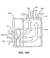
- a particularly useful embodiment of the present invention comprises the use of the inventive protective cover assembly in an electronic device that requires forced air cooling.
- Figure 10a shows an electronic device 100 comprising a protective cover assembly 14, apertures 101, fan 103 and other critical electronic components 104.
- the protective cover assembly 14 is disposed over the fan 103 to ensure adequate protection from the environment (i.e., dust, dirt, and common fluids) while also allowing reasonable air flow 105 (i.e., low air flow resistance) necessary to cool the critical electronic components 104.
- FIG. 2 shows an external front view of a conventional cellular phone housing 10 having small apertures 11 covering a microphone location 12 and loudspeaker 13a and alert 13b locations.
- the number, size and shape of the apertures may vary greatly.
- Aperture designs include slots, ovals, circles, or other combinations of shapes.
- FIG. 3 is an internal rear view of the housing 10 illustrating the same microphone location 12 and the loudspeaker and alert locations 13a and 13b.
- FIG. 3 illustrates generally a typical mounting location for protective cover assemblies 14 which are mounted in the microphone location 12 and the speaker and alert locations 13a and 13b.
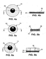
- FIGS. 4a and 4b illustrate a protective cover assembly 14 with a means for mounting to a housing 10 (not shown).
- an adhesive mounting system 24 is shown bonded to metal foil 20 with perforations 21 and treatment 25 (not shown).
- the adhesive mounting system 24 can be selected from many known materials well known in the art, such as thermoplastic, thermosetting, pressure-sensitive, or a reaction curing type, in liquid or solid form, selected from the classes including, but not limited to, acrylics, polyamides, polyacrylamides, polyesters, polyolefins, polyurethanes, polysilicons and the like.
- a pressure-sensitive adhesive mounting system 24 is most preferred, since it does not require heat or curing for mounting.
- the adhesive mounting system 24 can be applied directly to the metal foil 20 by screen printing, gravure printing, spray coating, powder coating, or other processes well known in the art.
- the adhesive mounting system 24 may be applied to the metal foil 20 in patterns, such as the ring-like shape shown in FIGS. 4a and 4b , continuously, using individual points, or in other patterns.
- the need for additional bonding points of the protective cover assembly 14 is dependent on the shape of the area or device to be covered as well as by the size of the protective cover assembly 14. Thus, some experimentation may be needed to establish the best method and pattern of additional bonding to optimize acoustic performance of the cover assembly 14.
- the adhesive mounting system 24 may also comprise a carrier (not shown), such as a mesh or film, to facilitate application of adhesive mounting system 24 onto metal foil 20.
- the adhesive mounting system 24 is simply a convenient means to mount the protective cover assembly 14 to the housing 10.
- Other means for mounting the protective cover assembly 14 to the housing 10 without the use of adhesives include heat staking, ultrasonic welding, press-fits, insert-molding, etc., which are processes well known in the art.
- FIGS. 5a-9b Other protective cover assembly 14 mounting systems follow in FIGS. 5a-9b .
- FIGS. 5a and 5b illustrate an acoustically transparent "sandwich construction" embodiment of a protective cover assembly 14 of the present invention.
- a “sandwich construction” describes the configuration of the protective cover assembly 14, where a metal foil 20 with perforations 21 and treatment 25 is generally “sandwiched" between a first adhesive support system 22 and a second adhesive support system 24.
- the adhesive support systems 22 and 24 are preferably bonded so that an inner unbonded region of the metal foil 20 surrounded by an outer bonded region is formed. In the unbonded region of the metal foil 20, the combination of the two adhesive support systems 22 and 24 provides focused acoustic energy between a transducer and the housing 10, resulting in lower acoustic loss.
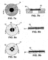
- FIGS. 6a and 6b illustrate an embodiment of a "sandwich construction" protective cover assembly 14 as shown in FIGS. 5a and 5b , wherein an acoustic gasket 34 is bonded to the first adhesive mounting system 22.
- the first adhesive mounting system 22 is a double-sided adhesive.
- the acoustic gasket 34 is attached to the first adhesive mounting system 22 and is designed to be compressed between a housing 10 and the acoustic transducer or PCB (not shown), so as to provide a seal and thus avoid acoustic leakage, as discussed in U.S. Patent Nos. 6,512,834 .
- Conventional commercially-available materials are known in the art and are suitable for use as the acoustic gasket 34 material.
- a preferred acoustic gasket 34 material is a microporous PTFE material, and more preferably, a microporous ePTFE having a microstructure of interconnected nodes and fibrils, as described in U.S. Patent Nos. 3,953,566 , 4,187,390 , and 4,110,392 .
- the acoustic gasket 34 material comprises a matrix of microporous PTFE, which may be partially filled with elastomeric materials.
- acoustic gasket 34 materials might include a metal-plated or particle-filled polymer that provides features such as conformability and electrical conductivity.
- the acoustic gasket 34 can be bonded to the cover materials using the methods and materials for bonding together the metal foil 20 and adhesive mounting systems 22 and 24.
- FIGS. 7a and 7b illustrate an alternative embodiment of a protective cover assembly 14 where the metal foil 20 with perforations 21 and treatment 25 is insert-molded into a plastic cap 36.
- Vulcanizable plastics like silicones or natural rubber, and thermoplastics, like polypropylene, polyethylene, polycarbonates or polyamides, as well as thermoplastic elastomers, like Santoprene® or Hytrel®, are particularly suitable as a material for the plastic cap 36, though many other plastic materials may be used as well.
- Most of these plastics can be used in the so-called insert-molding injection-molding process, which offers the significant advantage of integrating a metal foil 20 into a plastic cap 36 in one step. This type of process can offer high bond strength while also providing cost benefits.
- the metal foil 20 owing to its high temperature resistance, is particularly compatible with such an insert-molding process without damage to it.
- the metal foil 20 is illustrated as being molded in the middle of the plastic cap 36, it should be understood that other locations and techniques are possible (i.e. the metal foil 20 may be molded into a groove formulated in any vertical position on the cap 36.)
- FIGS. 8a, 8b, 9a and 9b are also "sandwich construction" embodiments as described above in all aspects, except that a supplemental bonding site 38 within the adhesive mounting system 22 and 24 spans across the metal foil 20.
- the supplemental bonding site 38 provides support for a protective cover assembly 14 with a relatively large inner unbonded region as discussed above.
- the supplemental bonding site 38 shown in the example has a defined geometry it should be noted that alternative supplemental bonding site geometries are possible and will be well understood by those skilled in the art.
- test specimen holder 44 that has an open-end termination instead of a closed-end termination.
- the open-end termination measurement is utilized to closely represent acoustic systems used in typical electronic devices and is more accurate when measuring thin, porous products.
- test specimen holder 44 is installed on the impedance tube 42 without a sample 66.
- a computer 70 communicates with the function generator/analyzer 60 which generates white noise and drives the speaker 46. Sound waves 68 from the speaker 46 propagate down the impedance tube 42. At the end of the test specimen holder 44, some sound waves 68 reflect back and microphones 50 and 52 measure the transfer function at the location where a sample is normally positioned. From the transfer function, the specific acoustic impedance is measured. This impedance measurement without a sample 66 is then saved in a computer 70 for post processing. Upon completion of the test, a sample 66 is placed into the test specimen holder 44 and the impedance test is again performed.
- This procedure for measurement provides an accurate and simple metric for comparing the specific acoustic impedance of a sample.
- the results can also be evaluated at a particular discrete or range of frequencies to determine any acoustic impedance frequency dependence within the material.
- the specific acoustic resistance Rs can be derived from the "complex" specific acoustic impedance Z by extracting the "real" part. Alternatively, extracting the "imaginary" part of the acoustic impedance will yield the specific acoustic reactance Xs, which is often displayed as a magnitude (i.e. values displayed are positive numbers).
- the specific acoustic resistance Rs will typically dominate the specific acoustic impedance.
- the specific acoustic reactance Xs will dominate the specific acoustic impedance. Both components are useful in determining acoustic performance, although the specific acoustic resistance may be more representative when measuring highly porous protective covers.
- I-WEP Instantaneous Water Entry Pressure
- I-WEP Instantaneous Water Entry Pressure
- test sample 72 is placed over the pressure cup 74.
- the clamping screen 76 is then secured and sealed to the pressure cup 74 to hold the sample securely in place.
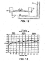
- the water pressure in the pressure cup 74 is then gradually increased at a constant rate of 2.5 cm/second by way of a water column 78 until evidence of water breakthrough occurs.
- the water pressure at breakthrough is then recorded as the I-WEP.
- the air flow resistance of samples was determined by using the Model 8160 Automated Filter Tester ("AFT"), manufactured by TSI and conducted in accordance with the procedure described in ASTM Test Method D726-58.
- the AFT is an automated filter that measures filter efficiency and penetration versus particle size as well as air flow resistance for air filtration media.
- the AFT determines the air flow resistance by measuring the pressure drop or pressure differential across the test specimen. The results are reported in millimeters of H 2 O for a given flow rate of 25 liters/min and a face velocity of 5.34 cm/s.
- a perforated nickel foil manufactured by Stork Veco B.V. was provided comprising the following nominal properties: thickness-0.0005" (12 micrometers); average maximum pore size - 87 micrometers; percent open area - 45%.
- a treatment was prepared using Teflon AF fluoropolymer from DuPont. The treatment consisted of 0.15% by weight of the Teflon AF in 99.85% by weight solvent, which was TF5070 from 3M. An adequate amount of coating solution was poured into a petri dish and the foil was fully immersed using tweezers. The treated foil was subsequently suspended in a fume hood for approximately 10 minutes. Specific acoustic resistance and reactance, along with I-WEP, and air flow resistance were tested according to the test methods outlined above. A comparison of the results from these tests are shown in Table 1 along with the material properties of thickness, and average maximum pore size.
- This example is a commercially available protective cover sold under the tradename SAATIFIL ACOUSTEXTM B010 by SaatiTech, a division of the Saati Group, Inc.
- the product consists of a polyester woven material.
- the material had the following nominal properties: thickness-105 micrometers; average maximum pore size - 120 micrometers; percent open area - 41%.
- Specific acoustic resistance and reactance, along with I-WEP, and air flow resistance were tested as described above. A comparison of the results from these tests are shown in Table 1 along with the material properties of thickness, and average maximum pore size.
- This example is a commercially available protective cover sold under the tradename GORETM PROTECTIVE COVER GAW101 manufactured by W. L. Gore & Associates, Inc.
- the product consists of a black, non-woven cellulose material.
- the material had the following nominal properties: thickness-150 micrometers; average maximum pore size - 56 micrometers.
- Specific acoustic resistance and reactance, along with I-WEP, and air flow resistance were tested as described above. A comparison of the results from these tests are shown in Table 1 along with the material properties of thickness, and average maximum pore size.
- This example is a commercially available protective cover sold under the tradename GORETM PROTECTIVE COVER GAW314 manufactured by W. L. Gore & Associates, Inc.
- the product consists of a black, ePTFE based material.
- the material had the following nominal properties: thickness-11 micrometers; average maximum pore size - 0.45 micrometers. A disc, 35mm diameter, was cut from the material. Specific acoustic resistance and reactance, along with I-WEP, and air flow resistance were tested as described above. A comparison of the results from these tests are shown in Table 1 along with the material properties of thickness, and average maximum pore size. Table 1 Average Specific Acoustic Impedance from 250 to 300 Hz (MKS Rayls) Average Instantaneous Water Entry Pressure Other Nominal Properties Examples Resistance (magnitude) Reactance (magnitude) I-WEP (cm) Airflow Resistance (mm of H 2 O) Thickness ( ⁇ m) Avg. Max Pore Size ( ⁇ m) Example 1 9 0 20 0.05 12 90 Comparative 1 11 1 11 0.05 105 158 Comparative 2 64 7 15 0.26 150 56 Comparative 3 5 86 >300 160.5 20 0.45
- Example 1 has improved average acoustic impedance over all of the Comparative Examples, which includes no measurable reactance.
- Example 1 shows equivalent air flow resistance with Comparative Example 1, but at a smaller maximum pore size, thereby providing a higher level of particulate protection.
- Example 1 provides these improvements while still maintaining a high level of water entry protection, sufficient for most portable device applications, for example a digital projector or notebook computer. If necessary, the water entry protection of Example 1 could be even further improved using other coating treatments described herein.
- Example 1 has the further advantages over the Comparative Examples of being electrically conductive, and compatible with standard insert molding processes.
- a further advantage of the exemplary embodiment is its EMI shielding effectiveness, which is shown in Figure 13 to be at least 50 dB, from 0 to 4 Gigahertz.
Landscapes
- Engineering & Computer Science (AREA)
- Physics & Mathematics (AREA)
- Acoustics & Sound (AREA)
- Signal Processing (AREA)
- Microelectronics & Electronic Packaging (AREA)
- Casings For Electric Apparatus (AREA)
- Telephone Set Structure (AREA)
- Details Of Audible-Bandwidth Transducers (AREA)
- Soundproofing, Sound Blocking, And Sound Damping (AREA)
Description
- The present invention generally relates to a cover providing environmental protection for a device, particularly an electronic device. More specifically, the present invention relates to a protective cover assembly comprising a treated perforated metal foil that has low specific acoustic resistance and reactance, low air flow resistance, high EMI shielding effectiveness, occupies limited space and has the ability to withstand exposure to dust and liquid intrusion.
- Most modem electronic devices, such as radios and cellular telephones, contain at least one component that needs to be protected from external contamination, such as liquids or dust An acoustic transducer such as a microphone, ringer, speaker, or buzzer is an example of a component that requires such protection. An acoustic transducer is an electrical component that converts electrical signals into sound, or vice-versa. Acoustic transducers are easily susceptible to being physically damaged, so they are often mounted in a protective housing with apertures located over the position of the acoustic transducer. These apertures enable the system to transmit or receive sound signals with minimal acoustic loss, while simultaneously preventing large debris from entering the housing and damaging the acoustic transducer. These apertures, however, do not protect the acoustic transducer from incidental exposure to liquids (e.g., spills, rain, etc.) or fine dust and other particulate. To protect acoustic transducers from contaminants such as these, a protective cover is typically utilized between the acoustic transducer and the housing, as a supplemental barrier to the apertures. A protective cover is thus simply a device that is intended to prevent unwanted contamination (liquid, particulate, or both) from reaching a susceptible component. For acoustic applications, it is desirable for the protective cover assembly to accomplish this contamination protection while minimizing the overall impact to the acoustic loss of the system.
- An acoustic transducer, as well as other components in an electronic device are also often susceptible to externally-generated EMI (electromagnetic interference) or ESD (electrostatic discharge). An unshielded electronic device can allow EMI to penetrate the device's housing, causing it function improperly. Additionally, a poorly protected electronic device can allow ESD to permanently damage certain sensitive components within the device. Shielding from EMI and ESD is typically accomplished by properly grounding components, and/or by providing a Faraday cage (or EMI shield) around these susceptible components. Since an EMI shield is, in essence, a metal or electrically conductive enclosure that surrounds the components, it will typically block or attenuate sound signals when shielding an acoustic transducer. In such situations, large holes or apertures in the EMI shield will lower the acoustic loss (thereby creating less attenuation) but it will also decrease the EMI shield's shielding effectiveness, as well as allow liquids, dust, and other contamination to penetrate the housing and reach the susceptible components. The properties of EMI and ESD protection, as well as contamination protection, are often therefore, competing properties. Accordingly, there exists a need in industry for a protective cover assembly that effectively blocks or limits EMI and ESD, has low acoustic loss, and prevents contamination from entering an electronic device's housing.
- Many electronic components, such as notebook computers, digital projectors, etc. also generate heat which must be dissipated. It is important to keep the internal temperatures of these electronic devices low because the failure rate of electronic components within them typically increase with higher temperatures. Many electronic devices use an electric fan to increase the air flow across the electronic components, thereby cooling them. These systems typically require holes or apertures in the housing to allow for cool air to be drawn in, and the heated air to be expelled. Larger holes will decrease the air flow resistance (thereby increasing the cooling effectiveness), but will also allow more opportunity for unwanted liquids and dust particles to enter the device's housing and cause potential damage to susceptible components.
- Accordingly, there exists a need in industry for a protective cover that provides low air flow resistance, effectively blocks or limits EMI and ESD, has low acoustic loss, and prevents contamination from entering the device's housing.
- Fortunately, a protective cover that has low air flow resistance will typically also contribute little to the acoustic loss of a system. The acoustic loss of a system (typically measured in decibels) is based on the characteristic elements/components that comprise the system, such as the housing aperture size, the volume of the cavity between the acoustic transducer and the protective cover, etc. The impact each element has on the overall acoustic loss of the system, independent of its area, can be determined individually by calculation or test; and this is called specific acoustic impedance.
- For most acoustic systems, the ideal protective cover would have a specific acoustic impedance value as small as possible. In some cases, however, the acoustic system (minus the protective cover) may contain sharp resonances at certain frequencies. In this case, a protective cover with a higher level of specific acoustic impedance can be effective at dampening the system resonances and ultimately flatten the spectrum for improved sound quality.
- Specific acoustic impedance can be measured in Rayls (MKS), and is composed of two terms: specific acoustic resistance and specific acoustic reactance. Specific acoustic resistance affects the specific acoustic impedance in a uniform manner across the frequency spectrum, and is related to viscous losses as air particles pass through any pores in the protective cover. These viscous losses are created by either friction of the air particle on the pore walls and/or a less direct air particle path (i.e. tortuous). Specific acoustic reactance, however, tends to affect the specific acoustic impedance in a more frequency-dependent manner, and is related to the movement/vibration of the protective cover in use. Because it has a non-uniform behavior with frequency, materials that are highly reactive are typically not selected for use as a protective cover, unless the application requires high environmental protection.
- As a general rule, the larger the pore size that exists in a protective cover (all else being equal), the lower the resulting specific acoustic resistance, the lower the air flow resistance, and the lower the level of liquid and particulate protection. Also generally speaking, the thinner the protective cover, the lower the specific acoustic resistance, as well. This is because, as the protective cover becomes thinner, lower viscous losses associated with air particles passing through the pores result. Non-porous covers or ones with very tight pore structures, however, tend to transmit sound via mechanical vibration of the protective cover (i.e. reactance), as opposed to physically passing air particles through the pores. Since vibration is required to transmit sound in this case, protective covers with high flexibility, low mass and less thickness are desired, in order to minimize specific acoustic reactance. These thin, low mass protective covers, however, can be more delicate, less durable, and more difficult to handle during fabrication and subsequent installation into an electronic device, so very low reactance may not be achievable in practice. The fact that the properties of specific acoustic resistance, specific acoustic reactance, durability, manufacturability, and contamination protection are often competing have made it difficult to develop protective covers that simultaneously meet aggressive acoustic, air flow, liquid and particulate protection targets. This has resulted in two major categories of protective covers: ones that can give high liquid and particulate protection, but with a relatively high air flow resistance and specific acoustic impedance (usually dominated by reactance); and ones that offer low air flow resistance and specific acoustic impedance, but with an accompanying low level of liquid and particulate protection.
- There are several different materials used in the construction of typical protective covers in use today. Many prior art protective covers are composed of a porous material constructed of synthetic or natural fibers, formed into either a woven or non-woven pattern. Other protective covers, such as microporous PTFE membranes, contain a network of interconnected nodes and fibrils. Finally, for very harsh or demanding environmental applications, some protective covers are composed entirely of non-porous films, such as polytetrafluoroethylene ("PTFE"), polyurethane, Mylar®, etc.
- A general description of prior art patents adhering to the above-described scientific principles follows.
-
U.S. Pat. No. 4,949,386 , entitled "Speaker System", teaches a protective cover comprising in part, a laminated two-layer construction defined by a polyester woven or non-woven material and a microporous PTFE membrane. The hydrophobic property of the microporous PTFE membrane prevents liquid from passing through the environmental barrier system. However, although this laminated covering system may be effective in preventing liquid entry into an electronic device, the lamination results in an excessively high specific acoustic impedance (dominated by reactance) which is unacceptable in modem communication electronics where sound quality is a critical requirement. -
U.S. Pat. No. 4,987,597 entitled "Apparatus For Closing Openings Of A Hearing Aid Or An Ear Adapter For Hearing Aids" teaches the use of a microporous PTFE membrane as a protective cover. The membrane effectively restricts liquid passage through the membrane but also results in a high specific acoustic impedance. Additionally, the patent fails to specifically teach the material parameters of the membrane that are required in order to achieve low specific acoustic impedance, although it does generally describe the parameters in terms of porosity and air permeability. -
U.S. Pat. No. 5,420,570 entitled "Manually Actuable Wrist Alarm Having A High-Intensity Sonic Alarm Signal" teaches the use of a non-porous film as a protective cover. As previously discussed, although a non-porous film can provide excellent liquid protection, such a non-porous film suffers from extremely high specific acoustic impedance, which is dominated by reactance. This can produce sound that is excessively muffled and distorted. The high specific acoustic reactance results from the relatively high mass and stiffness associated with typical non-porous films. -
U.S. Pat. No. 4,071,040 , entitled "Water-Proof Air Pressure Equalizing Valve," teaches the disposition of a thin microporous membrane between two sintered stainless steel disks. Although such a construction may have been effective for its intended use in rugged military-type field telephone sets, it is not desirable for use in modern communication electronic devices because the reactance is extremely high. This is because the two stainless steel disks physically constrain the membrane, limiting its ability to vibrate. Additionally, sintered metal disks are relatively thick and heavy and are thus impractical for lightweight, handheld portable electronic devices. - To overcome some of the shortcomings described above with respect to the '386, '597, '570 and '040 patents,
U.S. Patent No. 5,828,012 , entitled "Protective Cover Assembly Having Enhanced Acoustical Characteristics" teaches a protective cover comprising a membrane that is bonded to a porous support layer in a ring-like pattern. The construction results in an inner, unbonded region surrounded by an outer, bonded region. In this configuration, the membrane layer and the support layer are free to independently vibrate in response to acoustic energy passing therethrough, thereby minimizing the specific acoustic reactance over a completely laminated structure. However, although this construction reduces the reactance of the laminate comparatively, the degree of specific acoustic reactance still remains quite high. - To increase the simplicity, robustness, and improve the liquid protection of the construction described above with respect to the '012 patent,
U.S. Patent Nos. 6,512,834 entitled "Protective Acoustic Cover Assembly" teaches a protective cover that eliminates the need for a porous support layer. While this invention provides both improved water intrusion performance and acoustics over the '012 construction, the acoustic reactance still dominates the acoustic impedance. -
WO 02/45463 A2 -
US 5,342,434 (W. L. Gore & Associates, Inc.) describes flexible gas permeable materials that are hydrophobic and oleophobic. These materials can be used in filters that protect electronic equipment used in or near automotive engines. - Although the prior art mentioned above primarily discusses highly reactive materials, most commercially available protective covers are typically resistive. Examples of such resistive materials are a polyester woven material with the tradename SAATIFIL ACOUSTEX™ by SaatiTech, a division of the Saati Group, Inc. and nonwoven materials from Freudenberg Nonwovens NA and W. L. Gore & Associates, Inc. As mentioned previously, these materials can have a high specific acoustic resistance, which can be influenced by either their tortuous particle path and/or their increased material thickness. These physical material properties create higher viscous losses associated with the air particles passing through the pores. Because highly resistive materials are often highly undesirable in many applications, materials of this type can be produced with lower specific acoustic resistance, but this is usually accomplished by increasing the pore size of the material. This results in a decrease in the level of liquid and particulate protection.
- Because the consumer market desires the use of handheld electronic devices in increasingly harsh environments while simultaneously expecting high reliability and sound quality, the demand for durable, more contamination-resistant and less resistive/reactive protective covers has increased remarkably. In addition, as electronic devices become more portable and smaller, the heat load inside the enclosure increases thus increasing the need for ventilation. Therefore, there exists an unmet need to have a protective cover with low acoustic resistance, low air flow resistance, no measurable acoustic reactance, and a high level of water and particulate protection. The protective cover should also be durable and sufficiently rigid to facilitate the use of quick and accurate installation methods. It would also be highly desirable for the protective cover to offer additional properties and benefits such as: electrical conductivity for EMI shielding, grounding and ESD protection, high temperature and chemical resistance, and compatibility with insert-molding or heat-staking processes to simplify installation into a housing.
- The foregoing illustrates limitations known to exist in present protective covers for electronic and other devices. Thus, it is apparent that it would be advantageous to provide an improved protective cover to overcome one or more of the limitations set forth above. Accordingly, a suitable alternative is provided including features more fully disclosed hereinafter.
- According to aspects of the present invention there are provided a protective cover assembly, and an apparatus and method of protecting an electronic component disposed in a housing according to the appended claims.
- The present invention provides a protective cover assembly including a metal foil with perforations, and a treatment on one or more surfaces of said metal foil. The treatment is a modification of the surface of the foil to render it hydrophobic or oleophobic, or both. The protective cover assembly preferably has an average specific acoustic resistance of less than about 11 Rayls MKS from 250-300 Hz, an average specific acoustic reactance magnitude of less than about 1 Rayls MKS from 250-300 Hz, an air flow resistance of less than about 0.05 mm H2O, and an instantaneous water entry pressure value of greater than about 11 cm. The perforations of the metal foil preferably have an average maximum pore size of less than about 150 micrometers, and more preferably less than 100 micrometers. The protective cover assembly may further include an adhesive mounting system, and the preferred metal foil is nickel. The preferred thickness of the metal foil is less than about 20 micrometers.
- In another aspect, the present invention provides an apparatus including:
- (a) an electronic component;
- (b) a housing having at least one aperture, the housing at least partially enclosing the electronic component; and
- (c) a protective cover assembly disposed proximate the electronic component, the protective cover assembly including:
- (i) a metal foil with perforations, and
- (ii) a treatment on one or more surfaces of the metal foil.
- In this aspect, the protective cover assembly is integral with the housing absent any adhesive, for example by insert molding.
- In another aspect, the invention provides a method of protecting an electronic component disposed in a housing having an aperture by:
- (a) providing a protective cover assembly comprising:
- (i) a metal foil with perforations, and
- (ii) a treatment on one or more surfaces of the metal foil;
- (b) mounting the protective cover assembly proximate the electronic component to protect the electronic component from particulates and liquid ingress.
-
-
Fig. 1A is a plan view of a protective cover assembly according to an exemplary embodiment of the invention. -
Fig. 1B is a side view of the protective cover assembly ofFig. 1A . -
Fig. 2 is a view of the external side of a cellular phone housing according to an exemplary embodiment of the invention. -
Fig. 3 is a view of the internal side of a cellular phone housing according to an exemplary embodiment of the invention. -
Fig. 4A is a plan view of a protective cover assembly according to an exemplary embodiment of the invention. -
Fig. 4B is a side view of the protective cover assembly ofFig. 4A . -
Fig. 5A is a plan view of a protective cover assembly according to an exemplary embodiment of the invention. -
Fig. 5B is a side view of the protective cover assembly ofFig. 5A . -
Fig. 6A is a plan view of a protective cover assembly according to an exemplary embodiment of the invention. -
Fig. 6B is a side view of the protective cover assembly ofFig. 6A . -
Fig. 7A is a plan view of a protective cover assembly according to an exemplary embodiment of the invention. -
Fig. 7B is a side view of the protective cover assembly ofFig. 7A . -
Fig. 8A is a plan view of a protective cover assembly according to an exemplary embodiment of the invention. -
Fig. 8B is a side view of the protective cover assembly ofFig. 8A . -
Fig. 9A is a plan view of a protective cover assembly according to an exemplary embodiment of the invention. -
Fig. 9B is a side view of the protective cover assembly ofFig. 9A . -
Fig. 10A is a cross-sectional view of an electronic device according to an exemplary embodiment of the present invention. -
Fig. 10B is a perspective view of a digital projector according to an exemplary embodiment of the present invention. -
Fig. 10C is a perspective view of a notebook computer according to an exemplary embodiment of the present invention. -
Fig. 11 is a schematic of a test device used to measure acoustic transmission loss. -
Fig. 12 is a schematic of a test device used to measure instantaneous water entry pressure. -
Fig. 13 is a graph showing the shielding effectiveness of an exemplary embodiment of the present invention. - Referring now to the drawings, wherein similar reference characters designate corresponding parts throughout the several views, embodiments of the perforated acoustic cover assembly of the present invention are generally shown in a variety of configurations and dimensioned for use, in one embodiment, to cover a transducer in a typical electronic device, such as a cellular phone.
-
FIGS. 1a and 1b show aprotective cover assembly 14, according to a preferred embodiment of the invention. Theprotective cover assembly 14 is comprised of ametal foil 20 withperforations 21 and a hydrophobic oroleophobic treatment 25 on one or more of its surfaces. Theprotective cover assembly 14 may also comprise a supplementary means of mounting, as shown inFIG. 4a-10b ). Themetal foil 20 can be made of any metal, including but not limited to: nickel, aluminum, copper, silver, lead, platinum, iron, steel, chromium or alloys thereof. A metal such as nickel is preferred for its high electrical conductivity, ability to resist oxidation, mechanical robustness and strength, high temperature resistance, ability to be manufactured via a continuous electroforming process, and other advantageous processing characteristics. - The
metal foil 20 should be as thin as possible, while still maintaining physical robustness and ability to be manufactured and installed without damage. The thickness of the foil should be in the range of about 5 to 200 micrometers, and most preferably in the range 10 to 33 micrometers. Theperforations 21 in themetal foil 20 should have a maximum pore size (i.e. maximum opening distance within the perforation) in the range of 10 to 1000 micrometers, preferably below 150 micrometers, more preferably below 100 micrometers, and most preferably in the range of about 50 to 100 micrometers, for applications requiring both low acoustic impedance and high environmental protection. Theperforations 21 may be any shape, but are preferably round, oval, or hexagonal shaped. For most applications, theperforations 21 should preferably be as uniform and equidistant as possible across themetal foil 20 surface, and comprise a percent open area (i.e. the open pore area divided by the total sample area in percentage terms) of less than 65 percent, most preferably in the range of 5 to 45 percent. For applications where a higher resistance is desirable to dampen resonances, perforation sizes and percent open areas may be smaller. - The
metal foil 20 withperforations 21 may be manufactured by any of a number of known processes, which produce theperforations 21 in either a separate step after foil production (such as through mechanical punching, laser drilling, photoetching, etc.), or in-situ during the foil production itself (for example by stretching or drawing processes, powder sintering processes, electroforming processes, etc.). An electroforming process is a preferred embodiment for fabrication of themetal foil 20 withperforations 21, since it has the capability of being continuous in nature, thereby allowing for subsequent, cost-effective roll-to-roll processing of themetal foil 20. Electroforming also has the advantage of being able to produce large volumes of perforations, in various shapes and locations, with high uniformity, and at high speeds. Methods to produce such products are disclosed inU.S. Pat. Nos. 4,844,778 and other patents, can be used. - Still referring to
FIGS. 1a and 1b , themetal foil 20 has a hydrophobic (i.e. water-repellant) and/or oleophobic (i.e. oil-repellant)treatment 25 on at least one of its surfaces, to improve its resistance to liquids such as water, oils, or other low surface tension liquids. For example, the water- and oil-repellent treatments and methods disclosed inU.S. Pat. Nos. 5,116,650 ,5,286,279 ,5,342,434 ,5,376,441 and other patents, can be used. Other oleophobic treatments utilize coatings of fluorinated polymers such as, but not limited to: dioxole/TFE copolymers as those taught inU.S. Patents Nos. 5,385,694 and5,460,872 , perfluoroalkyl acrylates and perfluoroalkyl methacrylates such as those taught inU.S. Patent No. 5,462,586 , and fluoro-olefins and fluorosilicones. If it is a hydrophobic treatment, it may include use of hydrophobic nanoparticle silica particles. Alternatively,treatment 25 is a surface modification such as by plasma exposure. The treatments described herein in combination with the perforation size, shape, percent open area, and thickness of the metal foil interact to determine the final performance characteristics of the protective cover assembly. Accordingly, these features may be varied to optimize the final performance (e.g., acoustic resistance versus liquid protection) depending on the application requirements. - A particularly useful embodiment of the present invention comprises the use of the inventive protective cover assembly in an electronic device that requires forced air cooling.
Figure 10a shows anelectronic device 100 comprising aprotective cover assembly 14,apertures 101,fan 103 and other criticalelectronic components 104. Theprotective cover assembly 14 is disposed over thefan 103 to ensure adequate protection from the environment (i.e., dust, dirt, and common fluids) while also allowing reasonable air flow 105 (i.e., low air flow resistance) necessary to cool the criticalelectronic components 104. Those skilled in the art will realize that a different arrangement of the various components may be possible that still utilizes theprotective cover assembly 14 to protect criticalelectronic components 104. Examples of devices that use aprotective cover assembly 14 that would require natural or forced air to cool electrical components include digital projectors and notebook computers, which are shown inFigure 10b andFigure 10c , respectively, having reference numerals designating the same features as described above. -
FIG. 2 shows an external front view of a conventional cellular phone housing 10 havingsmall apertures 11 covering amicrophone location 12 andloudspeaker 13a and alert 13b locations. The number, size and shape of the apertures may vary greatly. Aperture designs include slots, ovals, circles, or other combinations of shapes. -
FIG. 3 is an internal rear view of the housing 10 illustrating thesame microphone location 12 and the loudspeaker andalert locations FIG. 3 illustrates generally a typical mounting location forprotective cover assemblies 14 which are mounted in themicrophone location 12 and the speaker andalert locations -
FIGS. 4a and 4b illustrate aprotective cover assembly 14 with a means for mounting to a housing 10 (not shown). In this example, anadhesive mounting system 24 is shown bonded tometal foil 20 withperforations 21 and treatment 25 (not shown). Theadhesive mounting system 24 can be selected from many known materials well known in the art, such as thermoplastic, thermosetting, pressure-sensitive, or a reaction curing type, in liquid or solid form, selected from the classes including, but not limited to, acrylics, polyamides, polyacrylamides, polyesters, polyolefins, polyurethanes, polysilicons and the like. A pressure-sensitiveadhesive mounting system 24 is most preferred, since it does not require heat or curing for mounting. Theadhesive mounting system 24 can be applied directly to themetal foil 20 by screen printing, gravure printing, spray coating, powder coating, or other processes well known in the art. Theadhesive mounting system 24 may be applied to themetal foil 20 in patterns, such as the ring-like shape shown inFIGS. 4a and 4b , continuously, using individual points, or in other patterns. For very largeacoustic cover assemblies 14 it may be more convenient to use widely separated bond lines instead of discrete bond points. The need for additional bonding points of theprotective cover assembly 14 is dependent on the shape of the area or device to be covered as well as by the size of theprotective cover assembly 14. Thus, some experimentation may be needed to establish the best method and pattern of additional bonding to optimize acoustic performance of thecover assembly 14. In general for a given protective cover assembly, to reduce its acoustic impedance and associated acoustic loss of its system, the area of the open unbonded region(s) or the area with open pores, should be maximized. Additionally, the adhesive mountingsystem 24 may also comprise a carrier (not shown), such as a mesh or film, to facilitate application of adhesive mountingsystem 24 ontometal foil 20. - The
adhesive mounting system 24 is simply a convenient means to mount theprotective cover assembly 14 to the housing 10. Other means for mounting theprotective cover assembly 14 to the housing 10 without the use of adhesives include heat staking, ultrasonic welding, press-fits, insert-molding, etc., which are processes well known in the art. - Other
protective cover assembly 14 mounting systems follow inFIGS. 5a-9b . -
FIGS. 5a and 5b illustrate an acoustically transparent "sandwich construction" embodiment of aprotective cover assembly 14 of the present invention. A "sandwich construction" describes the configuration of theprotective cover assembly 14, where ametal foil 20 withperforations 21 andtreatment 25 is generally "sandwiched" between a firstadhesive support system 22 and a secondadhesive support system 24. Theadhesive support systems metal foil 20 surrounded by an outer bonded region is formed. In the unbonded region of themetal foil 20, the combination of the twoadhesive support systems -
FIGS. 6a and 6b illustrate an embodiment of a "sandwich construction"protective cover assembly 14 as shown inFIGS. 5a and 5b , wherein anacoustic gasket 34 is bonded to the first adhesive mountingsystem 22. In this embodiment, the first adhesive mountingsystem 22 is a double-sided adhesive. Theacoustic gasket 34 is attached to the first adhesive mountingsystem 22 and is designed to be compressed between a housing 10 and the acoustic transducer or PCB (not shown), so as to provide a seal and thus avoid acoustic leakage, as discussed inU.S. Patent Nos. 6,512,834 . Conventional commercially-available materials are known in the art and are suitable for use as theacoustic gasket 34 material. For example, soft elastomeric materials or foamed elastomers, such as silicone rubber and silicone rubber foams, can be used. A preferredacoustic gasket 34 material is a microporous PTFE material, and more preferably, a microporous ePTFE having a microstructure of interconnected nodes and fibrils, as described inU.S. Patent Nos. 3,953,566 ,4,187,390 , and4,110,392 . Most preferably, theacoustic gasket 34 material comprises a matrix of microporous PTFE, which may be partially filled with elastomeric materials. These types of gaskets can offer thin profiles while also providing very low compression forces. Other types ofacoustic gasket 34 materials might include a metal-plated or particle-filled polymer that provides features such as conformability and electrical conductivity. Theacoustic gasket 34 can be bonded to the cover materials using the methods and materials for bonding together themetal foil 20 and adhesive mountingsystems -
FIGS. 7a and 7b illustrate an alternative embodiment of aprotective cover assembly 14 where themetal foil 20 withperforations 21 andtreatment 25 is insert-molded into aplastic cap 36. Vulcanizable plastics, like silicones or natural rubber, and thermoplastics, like polypropylene, polyethylene, polycarbonates or polyamides, as well as thermoplastic elastomers, like Santoprene® or Hytrel®, are particularly suitable as a material for theplastic cap 36, though many other plastic materials may be used as well. Most of these plastics can be used in the so-called insert-molding injection-molding process, which offers the significant advantage of integrating ametal foil 20 into aplastic cap 36 in one step. This type of process can offer high bond strength while also providing cost benefits. Themetal foil 20, owing to its high temperature resistance, is particularly compatible with such an insert-molding process without damage to it. Although themetal foil 20 is illustrated as being molded in the middle of theplastic cap 36, it should be understood that other locations and techniques are possible (i.e. themetal foil 20 may be molded into a groove formulated in any vertical position on thecap 36.) -
FIGS. 8a, 8b, 9a and 9b are also "sandwich construction" embodiments as described above in all aspects, except that asupplemental bonding site 38 within the adhesive mountingsystem metal foil 20. Thesupplemental bonding site 38 provides support for aprotective cover assembly 14 with a relatively large inner unbonded region as discussed above. Although thesupplemental bonding site 38 shown in the example has a defined geometry it should be noted that alternative supplemental bonding site geometries are possible and will be well understood by those skilled in the art. - Samples were tested and evaluated using the analysis procedures and methodology as described in ASTM E 1050-90, (Standard Test Method for Impedance and Absorption of Acoustical Materials Using a Tube, Two Microphones, and a Digital Frequency Analysis System). However, a modification to the ASTM standard was required to accurately evaluate the
protective cover assembly 14 and other competitive protective cover material samples. These modifications to the ASTM standard will be more readily understood and apparent when read in conjunction with the following description and while viewing accompanying drawings of the test sample holder inFIG. 11 . - The primary exception to ASTM 1050-90 is the use of a
test specimen holder 44 that has an open-end termination instead of a closed-end termination. The open-end termination measurement is utilized to closely represent acoustic systems used in typical electronic devices and is more accurate when measuring thin, porous products. - Initially, the
test specimen holder 44 is installed on theimpedance tube 42 without asample 66. Acomputer 70 communicates with the function generator/analyzer 60 which generates white noise and drives thespeaker 46.Sound waves 68 from thespeaker 46 propagate down theimpedance tube 42. At the end of thetest specimen holder 44, somesound waves 68 reflect back andmicrophones sample 66 is then saved in acomputer 70 for post processing. Upon completion of the test, asample 66 is placed into thetest specimen holder 44 and the impedance test is again performed. The original impedance is then simply subtracted from measured impedance of the sample to acquire the specific acoustic impedance of thesample 66. This is calculated using the specific acoustic impedance equation delineated in ASTM 1050-90 in conjunction with the following equation:
- This procedure for measurement provides an accurate and simple metric for comparing the specific acoustic impedance of a sample. The results can also be evaluated at a particular discrete or range of frequencies to determine any acoustic impedance frequency dependence within the material.
- Additionally, the specific acoustic resistance Rs can be derived from the "complex" specific acoustic impedance Z by extracting the "real" part. Alternatively, extracting the "imaginary" part of the acoustic impedance will yield the specific acoustic reactance Xs, which is often displayed as a magnitude (i.e. values displayed are positive numbers). For
protective cover assemblies 14 outlined herein and other protective covers that are highly porous, the specific acoustic resistance Rs will typically dominate the specific acoustic impedance. For non-porous protective covers or those with very tight pore structures, the specific acoustic reactance Xs will dominate the specific acoustic impedance. Both components are useful in determining acoustic performance, although the specific acoustic resistance may be more representative when measuring highly porous protective covers. - Instantaneous Water Entry Pressure ("I-WEP") provides a test method for water intrusion through highly porous materials. I-WEP is a measure of the sample's repellency or ability to serve as an aqueous barrier. This is an important property to consider and measure when designing electronic devices for water resistance applications. An illustration of the test device used to quantify I-WEP performance is shown in
FIG. 12 . - Initially, the
test sample 72 is placed over thepressure cup 74. Theclamping screen 76 is then secured and sealed to thepressure cup 74 to hold the sample securely in place. The water pressure in thepressure cup 74 is then gradually increased at a constant rate of 2.5 cm/second by way of awater column 78 until evidence of water breakthrough occurs. The water pressure at breakthrough is then recorded as the I-WEP. - Using an optical microscope with micron-sized measurement capabilities and a backlight, ten random pores within a sample are visually inspected and the largest opening within the pore is measured and recorded. These ten values are then averaged to give an average maximum pore size.
- The air flow resistance of samples was determined by using the Model 8160 Automated Filter Tester ("AFT"), manufactured by TSI and conducted in accordance with the procedure described in ASTM Test Method D726-58. The AFT is an automated filter that measures filter efficiency and penetration versus particle size as well as air flow resistance for air filtration media. The AFT determines the air flow resistance by measuring the pressure drop or pressure differential across the test specimen. The results are reported in millimeters of H2O for a given flow rate of 25 liters/min and a face velocity of 5.34 cm/s.
- The EMI shielding effectiveness of the samples were measured in accordance with ASTM D4935-99, "Standard Method for Measuring the Electromagnetic Shielding Effectiveness of Planar Materials".
- A perforated nickel foil manufactured by Stork Veco B.V. was provided comprising the following nominal properties: thickness-0.0005" (12 micrometers); average maximum pore size - 87 micrometers; percent open area - 45%. A disc, 35mm diameter, was cut from the material. A treatment was prepared using Teflon AF fluoropolymer from DuPont. The treatment consisted of 0.15% by weight of the Teflon AF in 99.85% by weight solvent, which was TF5070 from 3M. An adequate amount of coating solution was poured into a petri dish and the foil was fully immersed using tweezers. The treated foil was subsequently suspended in a fume hood for approximately 10 minutes. Specific acoustic resistance and reactance, along with I-WEP, and air flow resistance were tested according to the test methods outlined above. A comparison of the results from these tests are shown in Table 1 along with the material properties of thickness, and average maximum pore size.
- This example is a commercially available protective cover sold under the tradename SAATIFIL ACOUSTEX™ B010 by SaatiTech, a division of the Saati Group, Inc. The product consists of a polyester woven material. The material had the following nominal properties: thickness-105 micrometers; average maximum pore size - 120 micrometers; percent open area - 41%. A disc, 35mm diameter, was cut from the material. Specific acoustic resistance and reactance, along with I-WEP, and air flow resistance were tested as described above. A comparison of the results from these tests are shown in Table 1 along with the material properties of thickness, and average maximum pore size.
- This example is a commercially available protective cover sold under the tradename GORE™ PROTECTIVE COVER GAW101 manufactured by W. L. Gore & Associates, Inc. The product consists of a black, non-woven cellulose material. The material had the following nominal properties: thickness-150 micrometers; average maximum pore size - 56 micrometers. A disc, 35mm diameter, was cut from the material. Specific acoustic resistance and reactance, along with I-WEP, and air flow resistance were tested as described above. A comparison of the results from these tests are shown in Table 1 along with the material properties of thickness, and average maximum pore size.
- This example is a commercially available protective cover sold under the tradename GORE™ PROTECTIVE COVER GAW314 manufactured by W. L. Gore & Associates, Inc. The product consists of a black, ePTFE based material.
- The material had the following nominal properties: thickness-11 micrometers; average maximum pore size - 0.45 micrometers. A disc, 35mm diameter, was cut from the material. Specific acoustic resistance and reactance, along with I-WEP, and air flow resistance were tested as described above. A comparison of the results from these tests are shown in Table 1 along with the material properties of thickness, and average maximum pore size.
Table 1 Average Specific Acoustic Impedance from 250 to 300 Hz (MKS Rayls) Average Instantaneous Water Entry Pressure Other Nominal Properties Examples Resistance (magnitude) Reactance (magnitude) I-WEP (cm) Airflow Resistance (mm of H2O) Thickness (µm) Avg. Max Pore Size (µm) Example 1 9 0 20 0.05 12 90 Comparative 111 1 11 0.05 105 158 Comparative 264 7 15 0.26 150 56 Comparative 35 86 >300 160.5 20 0.45 - As can be seen from Table 1, the exemplary embodiment of this invention, illustrated by Example 1, has improved average acoustic impedance over all of the Comparative Examples, which includes no measurable reactance. Example 1 shows equivalent air flow resistance with Comparative Example 1, but at a smaller maximum pore size, thereby providing a higher level of particulate protection. Example 1 provides these improvements while still maintaining a high level of water entry protection, sufficient for most portable device applications, for example a digital projector or notebook computer. If necessary, the water entry protection of Example 1 could be even further improved using other coating treatments described herein. Example 1 has the further advantages over the Comparative Examples of being electrically conductive, and compatible with standard insert molding processes. In addition, a further advantage of the exemplary embodiment is its EMI shielding effectiveness, which is shown in
Figure 13 to be at least 50 dB, from 0 to 4 Gigahertz.
Claims (27)
- A protective cover assembly (14) comprising:a metal foil (20) with perforations (21), one or more of the surfaces of the metal foil (20) having been modified by a hydrophobic and/or oleophobic treatment (25),said protective cover assembly (14) having an air flow resistance of 0.05 mm of H20 or less for a given flow rate of 25 liters/min and a face velocity of 5.34 cm/s using a Model 8160 Automated Filter Test, manufactured by TSI, and conducted in accordance with the procedure described in ASTM Test Method D726-58.
- The protective cover assembly (14) of claim 1, wherein said protective cover assembly (14) has an instantaneous water entry pressure value of greater than 11 cm.
- The protective cover assembly (14) of claim 1, wherein said protective cover assembly (14) has a shielding effectiveness of greater than 50 decibels at 1 GHz.
- The protective cover assembly (14) of claim 1 wherein said perforations (21) have an average maximum pore size of less than 150 micrometers.
- The protective cover assembly (14) of claim 1 wherein said perforations (21) have an average maximum pore size of less than 100 micrometers.
- The protective cover assembly (14) of claim 1 wherein said perforations (21) have an average maximum pore size of between 50 and 100 micrometers.
- The protective cover assembly (14) of claim 1 wherein said treatment (25) includes hydrophobic treatment that comprises silica particles.
- The protective cover assembly (14) of claim 1 wherein said protective cover assembly (14) is less than 12 micrometers thick.
- The protective cover assembly (14) of claim 1 further comprising an adhesive mounting system.
- The protective cover assembly (14) of claim 1 wherein said metal foil (21) is nickel.
- A protective cover assembly (14) according to claim 1,
wherein said protective cover assembly (14) has an instantaneous water entry pressure value of greater than 11 cm;
said perforations (21) have an average maximum pore size of less than 150 micrometers; and
said metal foil (20) is nickel. - An apparatus comprising:(a) an electronic component transducer;(b) a housing (10) having at least one aperture, said housing (10) at least partially enclosing said electronic component;(c) a protective cover assembly (14) according to claim 1, the assembly (14) disposed proximate said electronic component.
- The apparatus of claim 12, wherein said perforations (21) of said metal foil (20) have an average maximum pore size of less than 150 micrometers.
- A method of protecting an electronic component disposed in a housing (10) having an aperture comprising the steps of:(a) providing a protective cover assembly (14) according to claim 1,(b) mounting said protective cover assembly (14) proximate said electronic component to protect said electronic component from particulates and liquid ingress.
- Apparatus according to claim 12, wherein the electronic component transducer is an acoustic transducer.
- The apparatus of claim 15, wherein said protective cover assembly (14) has an average specific acoustic reactance magnitude of less than 1 Rayls MKS (1 Ns/m3) from 250-300 Hz, conducted in accordance with the analysis procedures and methodology as described in ASTM E 1050-90, but modified by using a test specimen holder having an open-end termination instead of a closed-end termination.
- The apparatus of claim 15, wherein said protective cover assembly (14) has an instantaneous water entry pressure value of greater than 11 cm.
- The apparatus of claim 15 wherein said perforations (21) have an average maximum pore size of less than 150 micrometers.
- The apparatus of claim 15 wherein said protective cover assembly (14) further comprises an adhesive mounting system (24).
- The apparatus of claim 15 wherein said metal foil (20) is nickel.
- The apparatus of claim 15, wherein said protective cover assembly (14) is integral with said housing (10) absent any adhesive.
- An apparatus according to claim 15, wherein:(i) the metal foil (20) has perforations (21) having an average maximum pore size of less than 150 micrometers,(ii) the average specific acoustic resistance of less than about 11 Rayls MKS (11 Ns/m3) from 250-300 Hz, conducted in accordance with the analysis procedures and methodology as described in ASTM E 1050-90, but modified by using a test specimen holder having an open-end termination instead of a closed-end termination andwherein said protective cover assembly (14) further has:(i) an average specific acoustic reactance magnitude of less than 1 Rayls MKS (1 Ns/m3) from 250-300 Hz, conducted in accordance with the analysis procedures and methodology as described in ASTM E 1050-90, but modified by using a test specimen holder having an open-end termination instead of a closed-end termination, andii) an instantaneous water entry pressure value of greater than about 11 cm.
- A method according to claim 14, wherein the electronic component is an acoustic transducer.
- The method of claim 23 wherein said metal foil is nickel.
- The method of claim 23 wherein said perforations (21) have an average maximum pore size of less than 150 micrometers.
- The method of claim 23 wherein said protective cover assembly (14) has an instantaneous water entry pressure value of greater than 11 cm.
- A protective cover assembly (14) according to claim 1, wherein the protective cover assembly (10) has an average specific acoustic resistance of less than 11 Rayls MKS (11 Ns/m3) from 250-300 Hz, conducted in accordance with the analysis procedures and methodology as described in ASTM E 1050-90, but modified by using a test specimen holder having an open-end termination instead of a closed-end termination.
Priority Applications (1)
| Application Number | Priority Date | Filing Date | Title |
|---|---|---|---|
| EP14157892.2A EP2741522A1 (en) | 2003-10-14 | 2004-10-14 | Protective cover assembly |
Applications Claiming Priority (2)
| Application Number | Priority Date | Filing Date | Title |
|---|---|---|---|
| US10/686,036 US6932187B2 (en) | 2003-10-14 | 2003-10-14 | Protective acoustic cover assembly |
| PCT/US2004/033907 WO2005039234A2 (en) | 2003-10-14 | 2004-10-14 | Protective cover assembly |
Related Child Applications (2)
| Application Number | Title | Priority Date | Filing Date |
|---|---|---|---|
| EP14157892.2A Division-Into EP2741522A1 (en) | 2003-10-14 | 2004-10-14 | Protective cover assembly |
| EP14157892.2A Division EP2741522A1 (en) | 2003-10-14 | 2004-10-14 | Protective cover assembly |
Publications (3)
| Publication Number | Publication Date |
|---|---|
| EP1685740A2 EP1685740A2 (en) | 2006-08-02 |
| EP1685740A4 EP1685740A4 (en) | 2009-07-22 |
| EP1685740B1 true EP1685740B1 (en) | 2014-12-24 |
Family
ID=34423238
Family Applications (2)
| Application Number | Title | Priority Date | Filing Date |
|---|---|---|---|
| EP04795110.8A Expired - Lifetime EP1685740B1 (en) | 2003-10-14 | 2004-10-14 | Protective cover assembly |
| EP14157892.2A Withdrawn EP2741522A1 (en) | 2003-10-14 | 2004-10-14 | Protective cover assembly |
Family Applications After (1)
| Application Number | Title | Priority Date | Filing Date |
|---|---|---|---|
| EP14157892.2A Withdrawn EP2741522A1 (en) | 2003-10-14 | 2004-10-14 | Protective cover assembly |
Country Status (6)
| Country | Link |
|---|---|
| US (1) | US6932187B2 (en) |
| EP (2) | EP1685740B1 (en) |
| JP (1) | JP2007510326A (en) |
| KR (1) | KR100841508B1 (en) |
| CN (1) | CN1883242A (en) |
| WO (1) | WO2005039234A2 (en) |
Families Citing this family (103)
| Publication number | Priority date | Publication date | Assignee | Title |
|---|---|---|---|---|
| US6666295B2 (en) * | 2001-01-23 | 2003-12-23 | Etymotic Research, Inc. | Acoustic resistor for hearing improvement and audiometric applications, and method of making same |
| US7030482B2 (en) * | 2001-12-21 | 2006-04-18 | Intel Corporation | Method and apparatus for protecting a die ESD events |
| CN1316348C (en) | 2002-04-15 | 2007-05-16 | 埃波斯技术有限公司 | Method and system for obtaining positioning data |
| DE10260307B4 (en) * | 2002-12-20 | 2007-02-22 | Siemens Audiologische Technik Gmbh | Electroacoustic miniature transducer for a hearing aid |
| US6905000B1 (en) * | 2003-01-31 | 2005-06-14 | Plantronics, Inc. | Faceplate cover |
| US8457336B2 (en) * | 2004-02-05 | 2013-06-04 | Insound Medical, Inc. | Contamination resistant ports for hearing devices |
| US7283640B2 (en) * | 2004-02-10 | 2007-10-16 | Phonak Ag | Microphone cover |
| US20050249369A1 (en) * | 2004-05-05 | 2005-11-10 | Phonak Ag | Flexible frequency response shaping |
| US7852318B2 (en) * | 2004-05-17 | 2010-12-14 | Epos Development Ltd. | Acoustic robust synchronization signaling for acoustic positioning system |
| JP4521242B2 (en) * | 2004-09-30 | 2010-08-11 | 株式会社オーディオテクニカ | Boundary microphone |
| JP4188325B2 (en) * | 2005-02-09 | 2008-11-26 | ホシデン株式会社 | Microphone with built-in dustproof plate |
| EP2323017B1 (en) * | 2005-03-23 | 2016-06-29 | QUALCOMM Incorporated | Method and system for digital pen assembly |
| US7854819B2 (en) * | 2005-05-17 | 2010-12-21 | Panasonic Corporation | Multilayer information recording medium and production method therefor |
| JP4710622B2 (en) * | 2006-01-20 | 2011-06-29 | 日本電気株式会社 | Mobile terminal and noise prevention structure for mobile terminal |
| DE602007005405D1 (en) | 2006-01-26 | 2010-05-06 | Sonion Mems As | Elastomer shield for miniature microphones |
| US20070217641A1 (en) * | 2006-03-15 | 2007-09-20 | Rosal Mark B | Ear Gear |
| EP2005785B1 (en) * | 2006-03-17 | 2013-05-08 | Donaldson Company, Inc. | Hearing aid microphone cover |
| WO2008023991A1 (en) * | 2006-08-21 | 2008-02-28 | Rune Skramstad | A horn loudspeaker and a sound source |
| DK2060148T3 (en) * | 2006-08-31 | 2018-08-20 | Widex As | FILTER FOR A HEARING AND HEARING |
| DE102006046292B9 (en) * | 2006-09-29 | 2014-04-30 | Epcos Ag | Component with MEMS microphone and method of manufacture |
| EP2069082A4 (en) * | 2006-10-03 | 2011-11-09 | Sonic Innovations Inc | Hydrophobic and oleophobic coating and method for preparing the same |
| US8846161B2 (en) * | 2006-10-03 | 2014-09-30 | Brigham Young University | Hydrophobic coating and method |
| AU2007341776B2 (en) | 2007-01-03 | 2011-01-27 | Widex A/S | Component for a hearing aid and a method of making a component for a hearing aid |
| CN103399675B (en) * | 2007-03-14 | 2016-12-28 | 高通股份有限公司 | MEMS microphone |
| WO2008124786A2 (en) * | 2007-04-09 | 2008-10-16 | Personics Holdings Inc. | Always on headwear recording system |
| US7933122B2 (en) | 2007-06-06 | 2011-04-26 | Otter Products, Llc | Protective enclosure for a computer |
| JP5088779B2 (en) * | 2007-08-07 | 2012-12-05 | 日本ゴア株式会社 | Electroacoustic transducer, electronic device, waterproof cover, and ventilation test method for electroacoustic transducer |
| US8792658B2 (en) * | 2007-08-30 | 2014-07-29 | General Monitors, Inc. | Techniques for protection of acoustic devices |
| WO2009071942A2 (en) * | 2007-12-04 | 2009-06-11 | Bae Systems Plc | Improvements relating to sonar baffles and backings |
| US8172035B2 (en) * | 2008-03-27 | 2012-05-08 | Bose Corporation | Waterproofing loudspeaker cones |
| US7913808B2 (en) * | 2008-03-27 | 2011-03-29 | Bose Corporation | Waterproofing loudspeaker cones |
| US9280239B2 (en) * | 2008-05-22 | 2016-03-08 | Plantronics, Inc. | Touch sensitive controls with weakly conductive touch surfaces |
| JP5481852B2 (en) * | 2008-12-12 | 2014-04-23 | 船井電機株式会社 | Microphone unit and voice input device including the same |
| JP5171670B2 (en) * | 2009-01-29 | 2013-03-27 | 株式会社オーディオテクニカ | Condenser microphone unit |
| US8157048B2 (en) * | 2009-04-22 | 2012-04-17 | Gore Enterprise Holdings, Inc. | Splash proof acoustically resistive color assembly |
| US8731618B2 (en) * | 2009-04-23 | 2014-05-20 | Apple Inc. | Portable electronic device |
| US20100310194A1 (en) * | 2009-06-08 | 2010-12-09 | Roy Archambault | Waterproof, handheld electronic device enclosure |
| CN201491215U (en) * | 2009-07-17 | 2010-05-26 | 瑞声声学科技(常州)有限公司 | Minisize electroacoustic microphone |
| CN105307064A (en) * | 2009-09-04 | 2016-02-03 | 日东电工株式会社 | Sound-transmitting membrane for microphone, sound-transmitting membrane member for microphone provided with the membrane, microphone, and electronic device provided with microphone |
| US9165550B2 (en) | 2009-11-19 | 2015-10-20 | Otter Products, Llc | Acoustic isolation mechanism with membrane |
| US8479875B2 (en) | 2009-11-19 | 2013-07-09 | Otter Products, Llc | Acoustic isolation mechanism |
| US8290195B2 (en) * | 2010-03-31 | 2012-10-16 | Bose Corporation | Acoustic radiation pattern adjusting |
| JP4865052B2 (en) * | 2010-04-20 | 2012-02-01 | 株式会社東芝 | Electronics |
| EP2583733B1 (en) | 2010-06-16 | 2021-05-05 | Nitto Denko Corporation | Waterproof air-permeable filter and use of the same |
| US9044706B2 (en) | 2010-06-16 | 2015-06-02 | Nitto Denko Corporation | Water-proof air-permeable filter and use of the same |
| JP5709496B2 (en) * | 2010-12-07 | 2015-04-30 | 株式会社オーディオテクニカ | Acoustic resistance material and method of manufacturing acoustic resistance material |
| CN103404167B (en) * | 2011-01-18 | 2017-03-01 | 领先仿生公司 | Moistureproof earphone and the implantable cochlear stimulation system including moistureproof earphone |
| CN103404166B (en) * | 2011-03-03 | 2017-05-31 | 日东电工株式会社 | Waterproof sound passing membrane and electric product |
| ITMI20111579A1 (en) * | 2011-09-02 | 2013-03-03 | Saati Spa | MEMS MICROPHONE WITH INTEGRATED TEXTILE PROTECTION SCREEN. |
| CN103024614A (en) * | 2011-09-20 | 2013-04-03 | 深圳富泰宏精密工业有限公司 | Speaker protecting component and portable electronic device employing same |
| CN103051986A (en) * | 2011-10-13 | 2013-04-17 | 海能达通信股份有限公司 | Sound chamber structure and electroacoustic product |
| US8767992B2 (en) | 2011-12-30 | 2014-07-01 | Gary A. Lester, JR. | Mobile media device case/attachment for providing passive acoustic boosting |
| US9414141B2 (en) * | 2012-01-04 | 2016-08-09 | Apple Inc. | Mesh structure providing enhanced acoustic coupling |
| US8965025B2 (en) * | 2012-05-17 | 2015-02-24 | Aac Acoustic Technologies (Shenzhen) Co., Ltd. | Micro-speaker box |
| US9038773B2 (en) * | 2012-08-20 | 2015-05-26 | W. L. Gore & Associates, Inc. | Acoustic cover assembly |
| US8670586B1 (en) * | 2012-09-07 | 2014-03-11 | Bose Corporation | Combining and waterproofing headphone port exits |
| US8739926B1 (en) * | 2012-11-21 | 2014-06-03 | Nitto Denko Corporation | Sound-transmitting membrane and electronic device equipped with sound-transmitting membrane |
| JP5856102B2 (en) | 2012-11-21 | 2016-02-09 | 日東電工株式会社 | Sound-permeable structure, sound-permeable membrane, and waterproof case |
| US9514735B2 (en) * | 2012-12-11 | 2016-12-06 | Amogreentech Co., Ltd. | Waterproof sound transmitting sheet, and method for producing same |
| CN104159742B (en) * | 2012-12-11 | 2016-03-16 | 阿莫绿色技术有限公司 | The transaudient sheet material of waterproof and production method thereof |
| KR101509597B1 (en) | 2012-12-11 | 2015-04-07 | 주식회사 아모그린텍 | Waterproof sound-transmitting sheet and method for manufacturing thereof |
| JP2014175907A (en) * | 2013-03-11 | 2014-09-22 | Nitto Denko Corp | Waterproof sound-transmitting member |
| US9872099B2 (en) * | 2013-05-10 | 2018-01-16 | Goertek Inc. | Shutter covered on sound hole of loudspeaker module and assembling method thereof, loudspeaker module |
| US9002041B2 (en) * | 2013-05-14 | 2015-04-07 | Logitech Europe S.A. | Method and apparatus for improved acoustic transparency |
| US20150078609A1 (en) * | 2013-09-16 | 2015-03-19 | Merry Electronics (Suzhou) Co., Ltd. | Vent structure for electro-acoustic product, an electro-acoustic product housing using the vent structure |
| US9820038B2 (en) | 2013-09-30 | 2017-11-14 | Apple Inc. | Waterproof speaker module |
| KR102408259B1 (en) | 2013-10-30 | 2022-06-10 | 닛토덴코 가부시키가이샤 | Waterproof ventilation structure and waterproof ventilation member |
| US9414154B2 (en) * | 2014-04-03 | 2016-08-09 | Merry Electronics (Shenzhen) Co., Ltd. | Water-repellent earphone |
| US9226076B2 (en) | 2014-04-30 | 2015-12-29 | Apple Inc. | Evacuation of liquid from acoustic space |
| US9305538B2 (en) * | 2014-06-13 | 2016-04-05 | Alica Tyson | Transmission obscuring cover device |
| US20160376144A1 (en) * | 2014-07-07 | 2016-12-29 | W. L. Gore & Associates, Inc. | Apparatus and Method For Protecting a Micro-Electro-Mechanical System |
| JP6472182B2 (en) * | 2014-07-15 | 2019-02-20 | 日東電工株式会社 | Waterproof member and electronic device provided with the waterproof member |
| DE102014214547A1 (en) * | 2014-07-24 | 2016-01-28 | Sennheiser Electronic Gmbh & Co. Kg | Method for producing acoustic resistors |
| US9363589B2 (en) * | 2014-07-31 | 2016-06-07 | Apple Inc. | Liquid resistant acoustic device |
| US9681210B1 (en) | 2014-09-02 | 2017-06-13 | Apple Inc. | Liquid-tolerant acoustic device configurations |
| US10154327B2 (en) * | 2014-09-08 | 2018-12-11 | Apple Inc. | Molded acoustic mesh for electronic devices |
| US9538272B2 (en) * | 2014-09-08 | 2017-01-03 | Apple Inc. | Acoustic mesh and methods of use for electronic devices |
| CN105873386A (en) * | 2015-01-19 | 2016-08-17 | 富泰华工业(深圳)有限公司 | Electronic device shell |
| US9525924B2 (en) * | 2015-03-16 | 2016-12-20 | Microsoft Technology Licensing, Llc | Magnetic shielding and communication coil |
| CN104822102A (en) * | 2015-04-22 | 2015-08-05 | 歌尔声学股份有限公司 | Speaker module |
| CN107849280B (en) * | 2015-04-30 | 2021-07-23 | 日东电工株式会社 | Polymer resin film, breathable film, sound-transmitting film, acoustic resistor, acoustic device, and method for producing polymer resin film |
| CN204761633U (en) * | 2015-06-10 | 2015-11-11 | 瑞声光电科技(常州)有限公司 | Sounding device |
| US9811121B2 (en) | 2015-06-23 | 2017-11-07 | Apple Inc. | Liquid-resistant acoustic device gasket and membrane assemblies |
| US10110981B2 (en) * | 2015-06-30 | 2018-10-23 | W. L. Gore & Associates, Inc. | Vibro acoustic cover using expanded PTFE composite |
| US9545140B1 (en) | 2015-07-19 | 2017-01-17 | Otter Products, Llc | Protective enclosure for an electronic device |
| US9693134B2 (en) * | 2015-07-20 | 2017-06-27 | Nitto Denko Corporation | Waterproof sound-transmitting member |
| US9939783B2 (en) | 2015-08-19 | 2018-04-10 | Apple Inc. | Water resistant vent in an electronic device |
| US10015602B2 (en) | 2015-08-26 | 2018-07-03 | Cochlear Limited | Systems and methods for improving output signals from auditory prostheses |
| CN105681980A (en) * | 2015-12-31 | 2016-06-15 | 联想(北京)有限公司 | Electronic output equipment |
| KR102506823B1 (en) * | 2016-08-23 | 2023-03-07 | 삼성전자 주식회사 | Electronic device with speaker |
| US10209123B2 (en) | 2016-08-24 | 2019-02-19 | Apple Inc. | Liquid detection for an acoustic module |
| WO2018043224A1 (en) * | 2016-09-01 | 2018-03-08 | パナソニックIpマネジメント株式会社 | Speaker device and moving body device with same mounted thereon |
| KR101788112B1 (en) * | 2017-02-06 | 2017-10-20 | 주식회사 이엠텍 | High-pressure water resist microspeaker with improved coil structure |
| US10420406B2 (en) | 2017-02-16 | 2019-09-24 | Otter Products, Llc | Protective cover for electronic device |
| KR102318787B1 (en) * | 2017-09-19 | 2021-10-27 | 더블유.엘. 고어 앤드 어소시에이트스, 인코포레이티드 | Acoustic protective cover comprising a curable backing layer |
| CN208908495U (en) * | 2018-08-03 | 2019-05-28 | 瑞声科技(新加坡)有限公司 | Loudspeaker mould group |
| US10993009B2 (en) * | 2019-01-07 | 2021-04-27 | Bose Corporation | Earphone |
| CN110446139B (en) * | 2019-08-20 | 2022-03-15 | 歌尔股份有限公司 | Acoustic device and electronic apparatus |
| US10741160B1 (en) * | 2019-09-25 | 2020-08-11 | W. L. Gore & Associates, Inc. | Acoustically resistive supported membrane assemblies |
| US20220268800A1 (en) * | 2019-09-26 | 2022-08-25 | Molex, Llc | Hybrid sensor assembly for use with active noise cancellation |
| US11417311B2 (en) | 2020-08-03 | 2022-08-16 | W. L. Gore & Associates, Inc. | Acoustically resistive supported membrane assemblies including at least one support structure |
| IT202200014272A1 (en) * | 2022-07-06 | 2024-01-06 | Saati Spa | IMPROVED TYPE FABRIC FOR USE ON ACOUSTIC COMPONENTS OF ELECTRONIC DEVICES AND ACOUSTIC COMPONENT MADE WITH THIS FABRIC |
| WO2024009174A1 (en) | 2022-07-06 | 2024-01-11 | Saati S.P.A. | Improved textile protective element for use in acoustic components of electronic devices and acoustic component provided with this element inside |
Family Cites Families (27)
| Publication number | Priority date | Publication date | Assignee | Title |
|---|---|---|---|---|
| CA962021A (en) * | 1970-05-21 | 1975-02-04 | Robert W. Gore | Porous products and process therefor |
| JPS5554068Y2 (en) * | 1974-04-30 | 1980-12-15 | ||
| US4071040A (en) * | 1976-03-18 | 1978-01-31 | North Electric Company | Water-proof air-pressure equalizing valve |
| US4110392A (en) * | 1976-12-17 | 1978-08-29 | W. L. Gore & Associates, Inc. | Production of porous sintered PTFE products |
| US4194041A (en) * | 1978-06-29 | 1980-03-18 | W. L. Gore & Associates, Inc. | Waterproof laminate |
| AT378306B (en) * | 1983-08-29 | 1985-07-25 | Akg Akustische Kino Geraete | USE OF A BUNDLED LASER BEAM FOR PRODUCING AN ACOUSTIC FRICTION RESISTOR FOR ELECTROACOUSTIC TRANSDUCERS |
| JPH0649034Y2 (en) * | 1984-05-31 | 1994-12-12 | パイオニア株式会社 | Speaker waterproof cover |
| NL8603278A (en) * | 1986-12-23 | 1988-07-18 | Stork Veco Bv | MEMBRANE WITH PERFORATIONS AND METHOD FOR MANUFACTURING SUCH MEMBRANE. |
| DE8713369U1 (en) * | 1987-10-05 | 1989-02-09 | Siemens AG, 1000 Berlin und 8000 München | Device for closing openings on hearing aids or earpieces for hearing aids |
| US4852683A (en) * | 1988-01-27 | 1989-08-01 | Etymotic Research, Inc. | Earplug with improved audibility |
| US4949386A (en) * | 1988-05-23 | 1990-08-14 | Hill Amel L | Speaker system |
| US5116650A (en) * | 1990-12-03 | 1992-05-26 | W. L. Gore & Associates, Inc. | Dioxole/tfe copolymer composites |
| US5258746A (en) * | 1991-12-03 | 1993-11-02 | K & B Protection, Inc. | Manually actuatable wrist alarm having a high-intensity sonic alarm signal |
| US5338287A (en) * | 1991-12-23 | 1994-08-16 | Miller Gale W | Electromagnetic induction hearing aid device |
| US5222050A (en) * | 1992-06-19 | 1993-06-22 | Knowles Electronics, Inc. | Water-resistant transducer housing with hydrophobic vent |
| US5286279A (en) * | 1992-12-14 | 1994-02-15 | W. L. Gore & Associates, Inc. | Gas permeable coated porous membranes |
| US5342434A (en) * | 1992-12-14 | 1994-08-30 | W. L. Gore & Associates, Inc. | Gas permeable coated porous membranes |
| DE69333755T2 (en) * | 1993-03-26 | 2006-03-30 | W.L. Gore & Associates, Inc., Newark | Use of a coated polytetrafluoroethylene article for clothing |
| US5460872A (en) * | 1993-03-26 | 1995-10-24 | W. L. Gore & Associates, Inc. | Process for coating microporous substrates and products therefrom |
| JP2854223B2 (en) * | 1993-09-08 | 1999-02-03 | ジャパンゴアテックス株式会社 | Oil repellent waterproof ventilation filter |
| US5625688A (en) * | 1995-06-15 | 1997-04-29 | Jing Mei Industrial Holdings, Ltd. | Shower telephone |
| JP3629084B2 (en) * | 1996-01-24 | 2005-03-16 | 株式会社オーディオテクニカ | Waterproof microphone |
| US5828012A (en) * | 1996-05-31 | 1998-10-27 | W. L. Gore & Associates, Inc. | Protective cover assembly having enhanced acoustical characteristics |
| US6134333A (en) * | 1998-03-17 | 2000-10-17 | Sonic Innovations, Inc. | Disposable oleophobic and hydrophobic barrier for a hearing aid |
| JP3535412B2 (en) * | 1999-04-06 | 2004-06-07 | 株式会社巴川製紙所 | A conductive adhesive composition, a conductive adhesive sheet, an electromagnetic wave shielding material using the same, and an electromagnetic wave shielding flexible printed board. |
| US6512834B1 (en) * | 1999-07-07 | 2003-01-28 | Gore Enterprise Holdings, Inc. | Acoustic protective cover assembly |
| US7166910B2 (en) * | 2000-11-28 | 2007-01-23 | Knowles Electronics Llc | Miniature silicon condenser microphone |
-
2003
- 2003-10-14 US US10/686,036 patent/US6932187B2/en not_active Expired - Lifetime
-
2004
- 2004-10-14 JP JP2006535654A patent/JP2007510326A/en active Pending
- 2004-10-14 EP EP04795110.8A patent/EP1685740B1/en not_active Expired - Lifetime
- 2004-10-14 KR KR1020067009266A patent/KR100841508B1/en not_active IP Right Cessation
- 2004-10-14 WO PCT/US2004/033907 patent/WO2005039234A2/en active Application Filing
- 2004-10-14 CN CNA2004800301357A patent/CN1883242A/en active Pending
- 2004-10-14 EP EP14157892.2A patent/EP2741522A1/en not_active Withdrawn
Non-Patent Citations (2)
| Title |
|---|
| "Standard Test Method for Impedance and Absorption of Acoustical Materials Using a Tube, Two Microphones, and a Digital Frequency Analysis System", ASTM INTERNATIONAL, no. Designation: E 1050-90, 1 January 1990 (1990-01-01), pages 1 - 6, XP007922614 * |
| "Standard Test Method for Resistance of Nonporous Paper to Passage of Air", ASTM INTERNATIONAL, no. Designation: D726-94, 1 January 2003 (2003-01-01), pages 1 - 4, XP007922613 * |
Also Published As
| Publication number | Publication date |
|---|---|
| JP2007510326A (en) | 2007-04-19 |
| KR100841508B1 (en) | 2008-06-25 |
| EP1685740A4 (en) | 2009-07-22 |
| WO2005039234A3 (en) | 2006-07-27 |
| CN1883242A (en) | 2006-12-20 |
| EP1685740A2 (en) | 2006-08-02 |
| WO2005039234A2 (en) | 2005-04-28 |
| US20050077102A1 (en) | 2005-04-14 |
| US6932187B2 (en) | 2005-08-23 |
| EP2741522A1 (en) | 2014-06-11 |
| KR20060085958A (en) | 2006-07-28 |
Similar Documents
| Publication | Publication Date | Title |
|---|---|---|
| EP1685740B1 (en) | Protective cover assembly | |
| EP1197119B1 (en) | Acoustic protective cover assembly | |
| US5828012A (en) | Protective cover assembly having enhanced acoustical characteristics | |
| EP2422527B1 (en) | Splash proof acoustically resistive cover assembly | |
| CN110971995A (en) | Liquid-proof packaging for electroacoustic transducers and electronic devices | |
| WO2017176989A1 (en) | Pressure equalizing construction for nonporous acoustic membrane | |
| EP2561131A1 (en) | Textile laminar structure for making acoustic components | |
| WO2019093394A1 (en) | Waterproof sound-transmitting member and electronic device provided therewith | |
| JP2005334758A (en) | Ventilation filter |
Legal Events
| Date | Code | Title | Description |
|---|---|---|---|
| PUAI | Public reference made under article 153(3) epc to a published international application that has entered the european phase |
Free format text: ORIGINAL CODE: 0009012 |
|
| 17P | Request for examination filed |
Effective date: 20060413 |
|
| AK | Designated contracting states |
Kind code of ref document: A2 Designated state(s): AT BE BG CH CY CZ DE DK EE ES FI FR GB GR HU IE IT LI LU MC NL PL PT RO SE SI SK TR |
|
| AX | Request for extension of the european patent |
Extension state: AL HR LT LV MK |
|
| PUAK | Availability of information related to the publication of the international search report |
Free format text: ORIGINAL CODE: 0009015 |
|
| DAX | Request for extension of the european patent (deleted) | ||
| A4 | Supplementary search report drawn up and despatched |
Effective date: 20090623 |
|
| 17Q | First examination report despatched |
Effective date: 20101028 |
|
| RIC1 | Information provided on ipc code assigned before grant |
Ipc: H04R 1/08 20060101ALN20140402BHEP Ipc: H04R 1/02 20060101ALI20140402BHEP Ipc: H04R 1/00 20060101AFI20140402BHEP |
|
| GRAP | Despatch of communication of intention to grant a patent |
Free format text: ORIGINAL CODE: EPIDOSNIGR1 |
|
| RIC1 | Information provided on ipc code assigned before grant |
Ipc: H04R 1/00 20060101AFI20140417BHEP Ipc: H04R 1/02 20060101ALI20140417BHEP Ipc: H04R 1/08 20060101ALN20140417BHEP |
|
| INTG | Intention to grant announced |
Effective date: 20140520 |
|
| GRAP | Despatch of communication of intention to grant a patent |
Free format text: ORIGINAL CODE: EPIDOSNIGR1 |
|
| RIC1 | Information provided on ipc code assigned before grant |
Ipc: H04R 1/02 20060101ALI20140929BHEP Ipc: H04R 1/08 20060101ALN20140929BHEP Ipc: H04R 1/00 20060101AFI20140929BHEP |
|
| GRAS | Grant fee paid |
Free format text: ORIGINAL CODE: EPIDOSNIGR3 |
|
| INTG | Intention to grant announced |
Effective date: 20141030 |
|
| GRAA | (expected) grant |
Free format text: ORIGINAL CODE: 0009210 |
|
| AK | Designated contracting states |
Kind code of ref document: B1 Designated state(s): AT BE BG CH CY CZ DE DK EE ES FI FR GB GR HU IE IT LI LU MC NL PL PT RO SE SI SK TR |
|
| REG | Reference to a national code |
Ref country code: GB Ref legal event code: FG4D |
|
| REG | Reference to a national code |
Ref country code: CH Ref legal event code: EP |
|
| REG | Reference to a national code |
Ref country code: DE Ref legal event code: R081 Ref document number: 602004046398 Country of ref document: DE Owner name: W.L. GORE & ASSOCIATES, INC., NEWARK, US Free format text: FORMER OWNER: GORE ENTERPRISE HOLDINGS, INC., NEWARK, DEL., US |
|
| REG | Reference to a national code |
Ref country code: IE Ref legal event code: FG4D |
|
| REG | Reference to a national code |
Ref country code: AT Ref legal event code: REF Ref document number: 703653 Country of ref document: AT Kind code of ref document: T Effective date: 20150115 |
|
| REG | Reference to a national code |
Ref country code: DE Ref legal event code: R096 Ref document number: 602004046398 Country of ref document: DE Effective date: 20150212 |
|
| REG | Reference to a national code |
Ref country code: NL Ref legal event code: VDEP Effective date: 20141224 |
|
| PG25 | Lapsed in a contracting state [announced via postgrant information from national office to epo] |
Ref country code: FI Free format text: LAPSE BECAUSE OF FAILURE TO SUBMIT A TRANSLATION OF THE DESCRIPTION OR TO PAY THE FEE WITHIN THE PRESCRIBED TIME-LIMIT Effective date: 20141224 |
|
| PG25 | Lapsed in a contracting state [announced via postgrant information from national office to epo] |
Ref country code: GR Free format text: LAPSE BECAUSE OF FAILURE TO SUBMIT A TRANSLATION OF THE DESCRIPTION OR TO PAY THE FEE WITHIN THE PRESCRIBED TIME-LIMIT Effective date: 20150325 Ref country code: SE Free format text: LAPSE BECAUSE OF FAILURE TO SUBMIT A TRANSLATION OF THE DESCRIPTION OR TO PAY THE FEE WITHIN THE PRESCRIBED TIME-LIMIT Effective date: 20141224 |
|
| REG | Reference to a national code |
Ref country code: AT Ref legal event code: MK05 Ref document number: 703653 Country of ref document: AT Kind code of ref document: T Effective date: 20141224 |
|
| PG25 | Lapsed in a contracting state [announced via postgrant information from national office to epo] |
Ref country code: NL Free format text: LAPSE BECAUSE OF FAILURE TO SUBMIT A TRANSLATION OF THE DESCRIPTION OR TO PAY THE FEE WITHIN THE PRESCRIBED TIME-LIMIT Effective date: 20141224 |
|
| PG25 | Lapsed in a contracting state [announced via postgrant information from national office to epo] |
Ref country code: ES Free format text: LAPSE BECAUSE OF FAILURE TO SUBMIT A TRANSLATION OF THE DESCRIPTION OR TO PAY THE FEE WITHIN THE PRESCRIBED TIME-LIMIT Effective date: 20141224 Ref country code: RO Free format text: LAPSE BECAUSE OF FAILURE TO SUBMIT A TRANSLATION OF THE DESCRIPTION OR TO PAY THE FEE WITHIN THE PRESCRIBED TIME-LIMIT Effective date: 20141224 Ref country code: SK Free format text: LAPSE BECAUSE OF FAILURE TO SUBMIT A TRANSLATION OF THE DESCRIPTION OR TO PAY THE FEE WITHIN THE PRESCRIBED TIME-LIMIT Effective date: 20141224 Ref country code: EE Free format text: LAPSE BECAUSE OF FAILURE TO SUBMIT A TRANSLATION OF THE DESCRIPTION OR TO PAY THE FEE WITHIN THE PRESCRIBED TIME-LIMIT Effective date: 20141224 Ref country code: CZ Free format text: LAPSE BECAUSE OF FAILURE TO SUBMIT A TRANSLATION OF THE DESCRIPTION OR TO PAY THE FEE WITHIN THE PRESCRIBED TIME-LIMIT Effective date: 20141224 |
|
| REG | Reference to a national code |
Ref country code: GB Ref legal event code: 732E Free format text: REGISTERED BETWEEN 20150723 AND 20150729 |
|
| REG | Reference to a national code |
Ref country code: DE Ref legal event code: R082 Ref document number: 602004046398 Country of ref document: DE Representative=s name: MARKS & CLERK (LUXEMBOURG) LLP, LU Ref country code: DE Ref legal event code: R081 Ref document number: 602004046398 Country of ref document: DE Owner name: W.L. GORE & ASSOCIATES, INC., NEWARK, US Free format text: FORMER OWNER: GORE ENTERPRISE HOLDINGS, INC., NEWARK, DEL., US |
|
| PG25 | Lapsed in a contracting state [announced via postgrant information from national office to epo] |
Ref country code: AT Free format text: LAPSE BECAUSE OF FAILURE TO SUBMIT A TRANSLATION OF THE DESCRIPTION OR TO PAY THE FEE WITHIN THE PRESCRIBED TIME-LIMIT Effective date: 20141224 Ref country code: PL Free format text: LAPSE BECAUSE OF FAILURE TO SUBMIT A TRANSLATION OF THE DESCRIPTION OR TO PAY THE FEE WITHIN THE PRESCRIBED TIME-LIMIT Effective date: 20141224 |
|
| REG | Reference to a national code |
Ref country code: DE Ref legal event code: R097 Ref document number: 602004046398 Country of ref document: DE |
|
| RAP2 | Party data changed (patent owner data changed or rights of a patent transferred) |
Owner name: W.L. GORE & ASSOCIATES, INC. |
|
| PG25 | Lapsed in a contracting state [announced via postgrant information from national office to epo] |
Ref country code: DK Free format text: LAPSE BECAUSE OF FAILURE TO SUBMIT A TRANSLATION OF THE DESCRIPTION OR TO PAY THE FEE WITHIN THE PRESCRIBED TIME-LIMIT Effective date: 20141224 |
|
| PLBE | No opposition filed within time limit |
Free format text: ORIGINAL CODE: 0009261 |
|
| STAA | Information on the status of an ep patent application or granted ep patent |
Free format text: STATUS: NO OPPOSITION FILED WITHIN TIME LIMIT |
|
| 26N | No opposition filed |
Effective date: 20150925 |
|
| PG25 | Lapsed in a contracting state [announced via postgrant information from national office to epo] |
Ref country code: IT Free format text: LAPSE BECAUSE OF FAILURE TO SUBMIT A TRANSLATION OF THE DESCRIPTION OR TO PAY THE FEE WITHIN THE PRESCRIBED TIME-LIMIT Effective date: 20141224 |
|
| PG25 | Lapsed in a contracting state [announced via postgrant information from national office to epo] |
Ref country code: SI Free format text: LAPSE BECAUSE OF FAILURE TO SUBMIT A TRANSLATION OF THE DESCRIPTION OR TO PAY THE FEE WITHIN THE PRESCRIBED TIME-LIMIT Effective date: 20141224 |
|
| PG25 | Lapsed in a contracting state [announced via postgrant information from national office to epo] |
Ref country code: LU Free format text: LAPSE BECAUSE OF FAILURE TO SUBMIT A TRANSLATION OF THE DESCRIPTION OR TO PAY THE FEE WITHIN THE PRESCRIBED TIME-LIMIT Effective date: 20151014 Ref country code: BE Free format text: LAPSE BECAUSE OF FAILURE TO SUBMIT A TRANSLATION OF THE DESCRIPTION OR TO PAY THE FEE WITHIN THE PRESCRIBED TIME-LIMIT Effective date: 20141224 |
|
| REG | Reference to a national code |
Ref country code: CH Ref legal event code: PL |
|
| PG25 | Lapsed in a contracting state [announced via postgrant information from national office to epo] |
Ref country code: MC Free format text: LAPSE BECAUSE OF FAILURE TO SUBMIT A TRANSLATION OF THE DESCRIPTION OR TO PAY THE FEE WITHIN THE PRESCRIBED TIME-LIMIT Effective date: 20141224 |
|
| REG | Reference to a national code |
Ref country code: IE Ref legal event code: MM4A |
|
| PG25 | Lapsed in a contracting state [announced via postgrant information from national office to epo] |
Ref country code: CH Free format text: LAPSE BECAUSE OF NON-PAYMENT OF DUE FEES Effective date: 20151031 Ref country code: LI Free format text: LAPSE BECAUSE OF NON-PAYMENT OF DUE FEES Effective date: 20151031 |
|
| REG | Reference to a national code |
Ref country code: FR Ref legal event code: PLFP Year of fee payment: 13 |
|
| PG25 | Lapsed in a contracting state [announced via postgrant information from national office to epo] |
Ref country code: IE Free format text: LAPSE BECAUSE OF NON-PAYMENT OF DUE FEES Effective date: 20151014 |
|
| PGFP | Annual fee paid to national office [announced via postgrant information from national office to epo] |
Ref country code: FR Payment date: 20160921 Year of fee payment: 13 |
|
| PG25 | Lapsed in a contracting state [announced via postgrant information from national office to epo] |
Ref country code: BG Free format text: LAPSE BECAUSE OF FAILURE TO SUBMIT A TRANSLATION OF THE DESCRIPTION OR TO PAY THE FEE WITHIN THE PRESCRIBED TIME-LIMIT Effective date: 20141224 Ref country code: HU Free format text: LAPSE BECAUSE OF FAILURE TO SUBMIT A TRANSLATION OF THE DESCRIPTION OR TO PAY THE FEE WITHIN THE PRESCRIBED TIME-LIMIT; INVALID AB INITIO Effective date: 20041014 |
|
| PG25 | Lapsed in a contracting state [announced via postgrant information from national office to epo] |
Ref country code: CY Free format text: LAPSE BECAUSE OF FAILURE TO SUBMIT A TRANSLATION OF THE DESCRIPTION OR TO PAY THE FEE WITHIN THE PRESCRIBED TIME-LIMIT Effective date: 20141224 |
|
| PG25 | Lapsed in a contracting state [announced via postgrant information from national office to epo] |
Ref country code: TR Free format text: LAPSE BECAUSE OF FAILURE TO SUBMIT A TRANSLATION OF THE DESCRIPTION OR TO PAY THE FEE WITHIN THE PRESCRIBED TIME-LIMIT Effective date: 20141224 |
|
| REG | Reference to a national code |
Ref country code: FR Ref legal event code: ST Effective date: 20180629 |
|
| PG25 | Lapsed in a contracting state [announced via postgrant information from national office to epo] |
Ref country code: PT Free format text: LAPSE BECAUSE OF FAILURE TO SUBMIT A TRANSLATION OF THE DESCRIPTION OR TO PAY THE FEE WITHIN THE PRESCRIBED TIME-LIMIT Effective date: 20141224 |
|
| PG25 | Lapsed in a contracting state [announced via postgrant information from national office to epo] |
Ref country code: FR Free format text: LAPSE BECAUSE OF NON-PAYMENT OF DUE FEES Effective date: 20171031 |
|
| PGFP | Annual fee paid to national office [announced via postgrant information from national office to epo] |
Ref country code: GB Payment date: 20210922 Year of fee payment: 18 |
|
| GBPC | Gb: european patent ceased through non-payment of renewal fee |
Effective date: 20221014 |
|
| PG25 | Lapsed in a contracting state [announced via postgrant information from national office to epo] |
Ref country code: GB Free format text: LAPSE BECAUSE OF NON-PAYMENT OF DUE FEES Effective date: 20221014 |
|
| PGFP | Annual fee paid to national office [announced via postgrant information from national office to epo] |
Ref country code: DE Payment date: 20230920 Year of fee payment: 20 |