EP1684833B1 - Systeme d'ecran de securite pour seringue - Google Patents
Systeme d'ecran de securite pour seringue Download PDFInfo
- Publication number
- EP1684833B1 EP1684833B1 EP04795975.4A EP04795975A EP1684833B1 EP 1684833 B1 EP1684833 B1 EP 1684833B1 EP 04795975 A EP04795975 A EP 04795975A EP 1684833 B1 EP1684833 B1 EP 1684833B1
- Authority
- EP
- European Patent Office
- Prior art keywords
- medical device
- syringe barrel
- shield body
- barrel
- retainer
- Prior art date
- Legal status (The legal status is an assumption and is not a legal conclusion. Google has not performed a legal analysis and makes no representation as to the accuracy of the status listed.)
- Active
Links
- 239000003814 drug Substances 0.000 claims description 31
- 210000003813 thumb Anatomy 0.000 claims description 26
- 238000004891 communication Methods 0.000 claims description 3
- 239000012530 fluid Substances 0.000 claims description 3
- 229920003023 plastic Polymers 0.000 claims description 3
- 239000004033 plastic Substances 0.000 claims description 2
- 230000036541 health Effects 0.000 description 6
- 238000000034 method Methods 0.000 description 6
- 230000003993 interaction Effects 0.000 description 5
- 239000000463 material Substances 0.000 description 5
- 238000004519 manufacturing process Methods 0.000 description 3
- 230000004913 activation Effects 0.000 description 2
- 230000000712 assembly Effects 0.000 description 2
- 238000000429 assembly Methods 0.000 description 2
- 230000000994 depressogenic effect Effects 0.000 description 2
- 210000003811 finger Anatomy 0.000 description 2
- 239000011521 glass Substances 0.000 description 2
- 238000002347 injection Methods 0.000 description 2
- 239000007924 injection Substances 0.000 description 2
- 238000007689 inspection Methods 0.000 description 2
- 239000000126 substance Substances 0.000 description 2
- 206010069803 Injury associated with device Diseases 0.000 description 1
- 239000004743 Polypropylene Substances 0.000 description 1
- 239000004793 Polystyrene Substances 0.000 description 1
- NIXOWILDQLNWCW-UHFFFAOYSA-N acrylic acid group Chemical group C(C=C)(=O)O NIXOWILDQLNWCW-UHFFFAOYSA-N 0.000 description 1
- 230000009471 action Effects 0.000 description 1
- 239000008186 active pharmaceutical agent Substances 0.000 description 1
- 239000000853 adhesive Substances 0.000 description 1
- 230000001070 adhesive effect Effects 0.000 description 1
- 230000000903 blocking effect Effects 0.000 description 1
- 230000008859 change Effects 0.000 description 1
- 239000002537 cosmetic Substances 0.000 description 1
- 238000013461 design Methods 0.000 description 1
- 229940088679 drug related substance Drugs 0.000 description 1
- 230000000694 effects Effects 0.000 description 1
- 238000005429 filling process Methods 0.000 description 1
- 239000003292 glue Substances 0.000 description 1
- 238000003780 insertion Methods 0.000 description 1
- 230000037431 insertion Effects 0.000 description 1
- 239000007788 liquid Substances 0.000 description 1
- 230000007246 mechanism Effects 0.000 description 1
- 239000002991 molded plastic Substances 0.000 description 1
- 229920000515 polycarbonate Polymers 0.000 description 1
- 239000004417 polycarbonate Substances 0.000 description 1
- 239000005020 polyethylene terephthalate Substances 0.000 description 1
- 229920000139 polyethylene terephthalate Polymers 0.000 description 1
- 229920000379 polypropylene carbonate Polymers 0.000 description 1
- 229920002223 polystyrene Polymers 0.000 description 1
- 238000003825 pressing Methods 0.000 description 1
- 230000008569 process Effects 0.000 description 1
- 238000012545 processing Methods 0.000 description 1
- 230000001681 protective effect Effects 0.000 description 1
- 230000009467 reduction Effects 0.000 description 1
- 230000000284 resting effect Effects 0.000 description 1
- 239000007787 solid Substances 0.000 description 1
- 230000001954 sterilising effect Effects 0.000 description 1
- 238000004659 sterilization and disinfection Methods 0.000 description 1
- 238000003860 storage Methods 0.000 description 1
- 238000006467 substitution reaction Methods 0.000 description 1
- 229960005486 vaccine Drugs 0.000 description 1
Images


Classifications
-
- A—HUMAN NECESSITIES
- A61—MEDICAL OR VETERINARY SCIENCE; HYGIENE
- A61M—DEVICES FOR INTRODUCING MEDIA INTO, OR ONTO, THE BODY; DEVICES FOR TRANSDUCING BODY MEDIA OR FOR TAKING MEDIA FROM THE BODY; DEVICES FOR PRODUCING OR ENDING SLEEP OR STUPOR
- A61M5/00—Devices for bringing media into the body in a subcutaneous, intra-vascular or intramuscular way; Accessories therefor, e.g. filling or cleaning devices, arm-rests
- A61M5/178—Syringes
- A61M5/31—Details
- A61M5/32—Needles; Details of needles pertaining to their connection with syringe or hub; Accessories for bringing the needle into, or holding the needle on, the body; Devices for protection of needles
- A61M5/3205—Apparatus for removing or disposing of used needles or syringes, e.g. containers; Means for protection against accidental injuries from used needles
- A61M5/321—Means for protection against accidental injuries by used needles
- A61M5/3243—Means for protection against accidental injuries by used needles being axially-extensible, e.g. protective sleeves coaxially slidable on the syringe barrel
- A61M5/326—Fully automatic sleeve extension, i.e. in which triggering of the sleeve does not require a deliberate action by the user
- A61M2005/3261—Fully automatic sleeve extension, i.e. in which triggering of the sleeve does not require a deliberate action by the user triggered by radial deflection of the anchoring parts between sleeve and syringe barrel, e.g. spreading of sleeve retaining hooks having slanted surfaces by engagement with conically shaped collet of the piston rod during the last portion of the injection stroke of the plunger
Definitions
- the present invention relates to a prefilled medical device for delivering a dose of medicament by injection and having an integral shield system for preventing accidental needle sticks after use. More particularly, the present invention is directed to a syringe assembly including a safety shield system.
- Syringes used for the delivery of medicaments to patients are well known. Oftentimes syringes are prefilled with a dosage of a medicament or other substance by a pharmaceutical manufacturer and then distributed to end users such as health care professionals or patients for administration of the prefilled medicament.
- Such syringes typically include a cylindrical hollow barrel which may be formed of a glass or plastic material and which includes the medicament. One end of the barrel is fitted with a fixed or removable hollow needle, and the other end of the barrel receives a plunger having a stopper which is slidable with respect to the barrel for delivery of the medicament to the hollow needle, i.e., to urge the medicament toward and out of the needle.
- a syringe assembly which typically includes the above-described components, is usually stored with a removable needle cover which protects the needle from damage during storage and handling. Prior to use, the needle cover is removed to expose the needle.
- the syringe assembly may incorporate a safety shield which forms a guard to cover the needle after use, such as by telescopingly extending the shield from the syringe body over the needle.
- a safety shield which forms a guard to cover the needle after use, such as by telescopingly extending the shield from the syringe body over the needle.
- a medical device of the type as defined in the first paragraph of claim 1 is disclosed in US 6,585,702 B1 .
- This medical device is a single-use device for injection that includes a syringe barrel, a needle cannula, a plunger rod, a hollow shield body, retainer means for releasably securing the barrel in a first position and a spring for urging the syringe barrel from the first position toward a second position.
- a thumb pad interacting with the retainer means upon movement of the stopper is provided on a plunger that is movable with respect to the syringe barrel.
- the spring urging the barrel proximally with respect to the shield body is supported on one end on the protective sheath and with its opposite end at a shoulder of a locking ring having deflectable tabs for releasing the locking ring when the thumb pad reaches its most distal position.
- the shield should be intuitive and easy to use, should preferably provide consistent and reliable shield deployment, and should be operable with one hand.
- Other attributes are that such syringe assemblies require no change in current medicament delivery techniques, allow for dose adjustment, are preferably autoclavable, and allow for the inspection of contents before and after activation of the shield.
- the use of the shield must not detrimentally affect processing and filling of the syringe at the pharmaceutical company, the assembly (i.e., syringe assembly and safety shield) must be easy to manufacture, must prevent accidental activation, and must limit the possibility of incurring cosmetic or structural damages.
- the medical device may include a flange clip connected at a rear end of the shield body.
- the first retainer is arranged on the flange clip and the flange clip is placed about the shield body after the syringe barrel has been inserted into the shield body.
- the syringe barrel further comprises a radial flange arranged on an outer circumference of the syringe barrel between the front and rear ends thereof.
- the urging member may be arranged between the flange and a rearward facing step in the shield body.
- the flange clip may further include a second retainer which is used when the syringe barrel is moved to its fully retracted position. In that position, a forward facing portion of the syringe barrel flange is blocked from moving forward by the second retainer.
- the urging member is a spring which may be arranged between the rearward facing step in the shield body and a front face of the syringe barrel. In this latter embodiment, the spring does not hinder the view of the contents of the syringe barrel.
- the syringe assembly 20 includes a cylindrical barrel 24 defining a reservoir 25 within which the medicament may be held prior to use of the medical device 10.
- the syringe assembly 20 also includes a needle cannula 26 having a forward tip 126 and a rearward end 226 in fluid communication with the reservoir 25.
- the needle cannula 26 may be permanently connected to a front end of the barrel 24 using an adhesive, glue, interference fit or other known or hereafter developed material or technique, or it may be detachable from the barrel 24 such as, for example, using a luer-type connection.
- the barrel 24 also includes a radial flange 34 arranged between the ends of the barrel 24 which interacts with the shield body 22 as explained in detail below.
- a removable needle shield 27 is disposed over the needle cannula 26 on the front end of the barrel 24 to protect the needle from damage during handling of the syringe assembly, and to protect users from being stuck by the needle prior to its intended use.
- the needle shield 27 preferably includes a pliable part 127 and a rigid part 227.
- vent holes may be incorporated therein to allow the escape of moisture which may become trapped between the shield body 22 and the barrel 24 as a result of an autoclave or other sterilization process.
- windows may be cut or otherwise formed into the shield body 22 to allow for easier inspection of the syringe contents.
- an urging member 42 such as, for example, a coil spring or biasing arm, is positioned over the front end of the barrel 24 so that one end of the spring 42 rests against the radial flange 34 and the other end of the spring 42 is seated within the second cylindrical portion 38 of the shield body 22 and against the step 40.
- the spring 42 is charged in the assembled state of the device 10 shown in Fig. 2 and biases the syringe barrel 24 toward the second position in which the syringe barrel 24 is retracted into the shield body 22.
- the length and/or position of the spring 42 may be adjusted to increase or decrease the visible area of the barrel 24.
- a flange clip 44 is attached to the second free end 138 of the second cylindrical portion 38 of the shield body 22.
- the flange clip 44 has forward flexing arms 46a, .46b (collectively referred to as forward flexing arms 46) and rear flexing arms 48a, 48b (collectively referred to as rear flexing arms 48). Although two forward flexing arms 46 and two rear flexing arms 48 are shown, one or more of each of the flexing arms may be used to achieve the desired results described in detail below.
- An annular recess 50 is defined in the inner surface of the flange clip 44 between the forward and rear flexing arms 46, 48.
- This annular recess 50 receives a radial rim 52 arranged proximate the free end of the second cylindrical portion 38 on the shield body 22 as the flange clip 44 is inserted over the free end of the second cylindrical portion 38.
- the flange clip 44 is held in place on the shield body 22 and the barrel 24 is held within the shield body 22 in the position shown in Fig. 2 against the urgency of the spring 42 by the rear flexing arms 48. Accordingly, the rear flexing arms 48 also function as retainers.
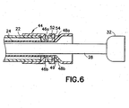
- Fig. 6 is an enlarged view of the interaction between the shield body 22, the flange clip 44 and the rear end of the barrel 24.
- the rear end of the barrel 24 is urged against axially forward facing surfaces of the rear flexing arms 48 in this state.
- the rear end of the barrel 24 may be flanged or otherwise suitably sized and shaped for this purpose.
- a portion of the forward flexing arms 46 extend through windows 54 in the shield body 22 in this state. The purpose of the forward flexing arms 46 is explained below.
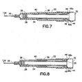
- Fig. 7 shows the medical device 10 during use, with the syringe barrel 24 deployed in the first position.
- the needle shield 27 (see Fig. 2 ) has been removed, the forward tip 126 of the needle cannula 26 is fully exposed, and the plunger 28 has been pushed into the barrel 24 such that a majority of the contents of the barrel 24 has been delivered.
- the flange clip 44, barrel 24 and shield body 22 are in the same relative positions in this state as in the state shown in Fig. 2 .
- Fig. 8 shows the medical device 10 after the plunger has been fully depressed into the barrel 24.
- the thumb pad 32 contacts the rear flexing arms 48 of the flange clip 44 and forces them to move radially outward relative to each other and the rear end of the barrel 24 no longer abuts the front facing portions 49 of the rear flexing arms 48.
- the urgency of the spring 42 moves the rear end of the barrel 24 against the front facing surface 29 of the thumb pad 32.
- Fig. 9 is an enlarged view of the interaction between the thumb pad 32, the flange clip 44, and the barrel 24 in this state.
- the front facing surface 29 of the thumb pad 32 may be conically-shaped as shown in Figs. 1 , 2 , and 3 .
- the front facing surface 29 of the thumb pad 32 may be configured as shown in Fig. 10a .
- any shape may be used as long is it has the desired effect of flexing the rear flexing arms 48 radially outward to the extent necessary to release the barrel 24 from flange clip 44.
- the thumb pad 32' may be configured as a mushroom-shaped head having a rim which overlaps a portion of the rear flexing arms 148 to urge the flexing arms radially inward toward each other.
- the rear retaining arms are designated as arms 148 and may be arranged on or connected to the barrel 24. As shown, the arms 148 engage a recess 150 arranged on or connected to the shield body 22.
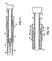
- the plunger 28 may be released by the operator of the medical device 10 and the syringe barrel 24 may move freely from the first position to the second position. This diminishes or removes the pressure applied to thumb pad 32. Thereafter the barrel 24 with the needle cannula 26 attached thereto will be caused by the spring 42 to retract into the shield body 22 until the radial flange 34 of the barrel 24 moves into a resting position between the forward and rear flexing arms 46, 48 as shown in Fig. 11 . Specifically, as the barrel 24 retracts, it follows the movement of the plunger and the radial flange 34 passes the forward flexing arms 46 and urges them radially outward from each other. As shown in Fig.
- the front facing surfaces of the forward flexing arms 46 are inclined with respect to each other and the rear facing surface of the radial flange 34 are inclined with respect to each other so that the forward flexing arms 46 slide over the radial flange 34 and move radially outward when the radial flange passes the forward flexing arms.
- the interaction between the radial flange 34 and the rear flexing arms 48 is such that the rear flexing arms are not forced radially outward by the radial flange, thereby locking radial flange 34 into position between arms 46, 48.
- This position corresponds to a fully retracted state of the barrel 24 so that the needle cannula 26 is fully received in the shield body 22 and the forward tip 126 of the needle cannula 26 is protected by the shield body 22.
- the barrel 24 is thereafter prevented from moving forward because the rear facing surface of the forward flexing arms 46 and the front facing surface of the radial flange 34 are not inclined.
- Fig. 13 shows an alternative embodiment in which the urging member 42 is arranged between a step 40' proximate a front end of a shield body 22' and a front face of the barrel 24.
- This embodiment allows the entire dosage of medicament to be viewed because the urging member 42 is arranged in front of the barrel 24.
- the flange 34 (not shown in Fig. 13 ) is used only to retain the barrel in the fully retracted position.
- a longer needle cannula 26' relative to the needle cannula 26 in the previously-discussed embodiments may be required to provide proper clearance of the front of the shield body 22'.
- Fig. 14 shows yet a further embodiment in which the barrel 24' includes two radial flanges 34a, 34b.
- this embodiment only one pair of flexing arms 48a', 48b' is required.
- This embodiment also shows that the flexing arms 48a', 48b' are formed as one piece with the shield body 22".
- the spring 42 is designed to push the barrel 24' to a position in which only one of the radial flanges 34b passes the flexing arms 48a', 48b'.
- the flexing arms 48a', 48b' block movement of the barrel 24' in both the forward and rearward movements relative to the shield body 22".
- one or more flexing arms 48' may be used.
- the health care professional receives the inventive medical device 10 prefilled with a desired single dosage of a medicament.
- the needle shield 27 is removed and the needle cannula 26 and forward tip 126 are exposed.
- the health care professional pierces the patient's skin with the forward tip 126 of the needle cannula 26 and depresses the thumb pad 32 to cause the plunger rod 28 and piston 30 to move within the reservoir 25.
- the medicament is caused to be expelled from the reservoir, through the needle cannula 24, and into the patient.
- the thumb pad 32 interacts with the flange clip 44, as described in detail above, thereby releasing the syringe barrel 24 and enabling the syringe barrel 24 to move from the first position to the second position under the force of the spring or urging member 42.
- the forward tip 126 of the needle cannula 24 will be completely contained within the shield body 22, thus preventing undesired and inadvertent exposure of the health care professional to the contaminated forward tip 126.
- the used medical device 10 may then be disposed of in a suitable sharps disposal container.
Claims (15)
- Dispositif médical pour administrer un médicament à un patient, comprenant :un cylindre de seringue (24) ayant une extrémité avant et une extrémité arrière et définissant un réservoir (25) à l'intérieur duquel le médicament peut être contenu ;une canule d'aiguille (26) ayant une pointe avant (126) et une extrémité arrière (226) couplée à ladite extrémité avant dudit cylindre de seringue (24) et étant en communication fluidique avec ledit réservoir (25) ;une tige de piston (28) ayant une première extrémité avec un bouchon (30) positionné dans ledit réservoir (25) et une deuxième extrémité ayant un poussoir (32) pour recevoir une pression d'administration de médicament afin d'amener ledit bouchon (30) à se déplacer à l'intérieur dudit réservoir (25) pour amener le médicament à être expulsé à partir de celui-ci ;un corps de protection creux (22) recevant ledit cylindre de seringue (24) dedans, ledit cylindre (24) pouvant être déplacé de manière sélective à l'intérieur dudit corps de protection (22) entre une première position dans laquelle ladite pointe avant (126) de ladite canule d'aiguille (26) est exposée, et une deuxième position dans laquelle ladite pointe avant (126) de ladite canule d'aiguille (26) est contenue à l'intérieur dudit corps de protection (22) ;un moyen de retenue pour fixer de manière amovible ledit cylindre de seringue (24) dans ladite première position ; etun moyen de sollicitation (42) agencé entre une partie dudit corps de protection creux (22) et une partie dudit cylindre de seringue (24) pour solliciter ledit cylindre de seringue (24) de ladite première position vers ladite deuxième position ;ledit poussoir (32) interagissant avec ledit moyen de retenue lors du mouvement dudit bouchon (30) vers une position à proximité de ladite extrémité avant de cylindre pour libérer ledit cylindre de seringue (24) dudit moyen de retenue et permettre audit moyen de sollicitation (42) de déplacer ledit cylindre de seringue (24) de ladite première position à ladite deuxième position lors de la libération d'une pression d'administration de médicament à partir dudit poussoir (32) ;ledit moyen de retenue comprend une attache de bride prévue sur ledit corps de protection creux (22) à proximité d'une extrémité orientée vers l'arrière de celui-ci,ledit corps de protection creux (22) comprend un ressaut (40) ayant une surface orientée vers l'arrière pour recevoir une extrémité dudit moyen de sollicitation (42), etcaractérisé en ce queledit cylindre de seringue (24) a une bride radiale (34) définie sur une circonférence externe de celui-ci, ladite bride radiale (34) définissant une surface de butée pour ledit moyen de sollicitation (42) et comprenant un moyen de verrouillage pour verrouiller ledit cylindre (24) dans ladite deuxième position.
- Dispositif médical de la revendication 1, dans lequel ledit corps de protection creux (22) comprend en outre un rebord et ladite attache de bride (44) comprend un évidement s'engageant avec ledit rebord pour relier ladite attache de bride (44) audit corps de protection creux (22).
- Dispositif médical de la revendication 1, dans lequel ledit ressaut (40) divise ledit corps de protection creux en une première partie cylindrique (36) ayant un premier diamètre et une deuxième partie cylindrique (38) ayant un deuxième diamètre différent dudit premier diamètre, ledit moyen de sollicitation (42) étant agencé dans ladite deuxième partie cylindrique (38).
- Dispositif médical de la revendication 1, dans lequel ladite attache de bride (44) comprend un élément de retenue espacé axialement dudit moyen de retenue, dans lequel ladite bride radiale est positionnée entre ledit élément de retenue et ledit moyen de retenue lorsque ledit cylindre de seringue (24) est dans ladite deuxième position.
- Dispositif médical de la revendication 4, dans lequel une surface orientée vers l'avant dudit élément de retenue et une surface orientée vers l'arrière de ladite bride radiale sont mutuellement inclinées pour permettre à ladite bride de passer sur ledit élément de retenue lorsque ledit cylindre de seringue (24) est déplacé de ladite première position vers ladite deuxième position.
- Dispositif médical de la revendication 4, dans lequel ledit élément de retenue et ledit moyen de retenue comprennent des bras flexibles.
- Dispositif médical de la revendication 1, dans lequel ledit élément de sollicitation (42) comprend un ressort.
- Dispositif médical de la revendication 1, dans lequel ledit moyen de retenue (44) est formé d'un seul tenant avec ledit corps de protection (22).
- Dispositif médical de la revendication 1, dans lequel ledit cylindre de seringue (24) comprend en outre deux brides radiales espacées axialement (34a, 34b).
- Dispositif médical de la revendication 9, dans lequel ledit moyen de retenue (44) est agencé axialement entre lesdites deux brides radiales espacées axialement (34a, 34b) et empêche un mouvement vers l'avant et vers l'arrière dudit cylindre de seringue (24) par rapport audit corps de protection creux (22) lorsque ledit cylindre de seringue (24) est agencé dans ladite deuxième position.
- Dispositif médical de la revendication 1, dans lequel ledit cylindre de seringue (24) est en plastique.
- Dispositif médical de la revendication 7, dans lequel ledit corps de protection (22) comprend un ressaut (40) ayant une surface orientée vers l'arrière pour recevoir une extrémité dudit ressort (42).
- Dispositif médical de la revendication 12, dans lequel ledit ressaut (40) divise ledit corps de protection creux (22) en une première partie cylindrique (36) ayant un premier diamètre et une deuxième partie cylindrique (38) ayant un deuxième diamètre différent dudit premier diamètre, ledit ressort (42b) étant agencé dans ladite deuxième partie cylindrique (38).
- Dispositif médical de la revendication 1, dans lequel ledit moyen de retenue (44) est déplacé radialement vers l'extérieur pour libérer ledit cylindre de seringue (24).
- Dispositif médical de la revendication 1, dans lequel ledit moyen de retenue (44) est déplacé radialement vers l'intérieur pour libérer ledit cylindre de seringue (24).
Applications Claiming Priority (2)
| Application Number | Priority Date | Filing Date | Title |
|---|---|---|---|
| US10/699,808 US7468054B2 (en) | 2003-11-03 | 2003-11-03 | Safety shield system for a syringe |
| PCT/US2004/034893 WO2005044352A1 (fr) | 2003-11-03 | 2004-10-21 | Systeme d'ecran de securite pour seringue |
Publications (2)
| Publication Number | Publication Date |
|---|---|
| EP1684833A1 EP1684833A1 (fr) | 2006-08-02 |
| EP1684833B1 true EP1684833B1 (fr) | 2015-03-04 |
Family
ID=34551049
Family Applications (1)
| Application Number | Title | Priority Date | Filing Date |
|---|---|---|---|
| EP04795975.4A Active EP1684833B1 (fr) | 2003-11-03 | 2004-10-21 | Systeme d'ecran de securite pour seringue |
Country Status (5)
| Country | Link |
|---|---|
| US (1) | US7468054B2 (fr) |
| EP (1) | EP1684833B1 (fr) |
| JP (1) | JP4658956B2 (fr) |
| ES (1) | ES2538354T3 (fr) |
| WO (1) | WO2005044352A1 (fr) |
Families Citing this family (15)
| Publication number | Priority date | Publication date | Assignee | Title |
|---|---|---|---|---|
| DE10337138A1 (de) * | 2003-08-11 | 2005-03-17 | Freitag, Lutz, Dr. | Verfahren und Anordnung zur Atmungsunterstützung eines Patienten sowie Luftröhrenprothese und Katheter |
| US7294119B2 (en) * | 2004-06-10 | 2007-11-13 | Safety Syringes, Inc. | Passive delivery system diluents mixing and delivery |
| US7559919B2 (en) * | 2006-04-21 | 2009-07-14 | West Pharmaceutical Services, Inc. | Needle shield |
| DE202007005394U1 (de) * | 2007-04-13 | 2007-08-09 | B. Braun Melsungen Ag | Sicherheitsspritze |
| GB2452030A (en) * | 2007-08-10 | 2009-02-25 | Owen Mumford Ltd | Injection devices |
| AU2010336003B2 (en) | 2009-12-22 | 2014-07-03 | Unitract Syringe Pty Ltd | Retractable syringe with improved delivery efficiency and locking system |
| US8920385B2 (en) | 2010-05-05 | 2014-12-30 | Safety Syringes, Inc. | Extended finger flange for syringe systems |
| US8652104B2 (en) | 2010-06-25 | 2014-02-18 | Smiths Medical Asd, Inc. | Catheter assembly with seal member |
| US9545495B2 (en) | 2010-06-25 | 2017-01-17 | Smiths Medical Asd, Inc. | Catheter assembly with seal member |
| EP2585145B1 (fr) | 2010-08-19 | 2014-03-05 | West Pharmaceutical Services, Inc. | Gaine d'aiguille rigide |
| IN2014CN03380A (fr) | 2011-11-07 | 2015-10-09 | Safety Syringes Inc | |
| US9186466B2 (en) | 2012-03-14 | 2015-11-17 | Becton, Dickinson And Company | Passively activated safety needle assemblies and methods of use |
| BR112015010607A2 (pt) | 2012-11-09 | 2017-12-05 | Iinjec Tech Inc | injetor de entrega de fluido, montagem de agulha retrátil e método para injetar pelo menos uma dose de uma medicação fluida transcutaneamente no corpo. |
| USD765838S1 (en) | 2015-03-26 | 2016-09-06 | Tech Group Europe Limited | Syringe retention clip |
| US11587463B2 (en) * | 2016-10-18 | 2023-02-21 | Merck Sharp & Dohme Llc | Patient training device for use with a safety syringe injector |
Family Cites Families (104)
| Publication number | Priority date | Publication date | Assignee | Title |
|---|---|---|---|---|
| US4573976A (en) * | 1984-05-24 | 1986-03-04 | Dolores A. Smith | Shielded needle |
| US4631057A (en) * | 1985-12-17 | 1986-12-23 | Dolores A. Smith | Shielded needle |
| ES2020280B3 (es) * | 1986-11-19 | 1991-08-01 | Sterimatic Holdings Ltd | Mejoras en o relacionadas con jeringas. |
| US4795432A (en) * | 1987-02-19 | 1989-01-03 | Karczmer Claude M | Shield assembly for hypodermic injection devices |
| US4737144A (en) * | 1987-03-09 | 1988-04-12 | Choksi Pradip V | Syringe with selectively exposed and enveloped needle |
| US4747831A (en) * | 1987-04-29 | 1988-05-31 | Phase Medical, Inc. | Cannula insertion set with safety retracting needle |
| US4850968A (en) | 1987-07-27 | 1989-07-25 | Ar.Ma.S.R.L. | Self-blocking hypodermic syringe for once-only use, comprising a needle protection cap |
| US5217437A (en) * | 1988-06-28 | 1993-06-08 | Sherwood Medical Company | Needle protecting device |
| US5053018A (en) * | 1988-06-28 | 1991-10-01 | Sherwood Medical Company | Combined syringe and needle shield and method of manufacture |
| US5156599A (en) * | 1988-06-28 | 1992-10-20 | Sherwood Medical Company | Syringe and sliding locking needle shield |
| US4985021A (en) * | 1989-01-31 | 1991-01-15 | Jeff Straw | Safety enclosure system for medical devices |
| US6017329A (en) * | 1989-03-02 | 2000-01-25 | Hake; Lawrence W. | Hypodermic needle guard and method to prevent needle stick injuries |
| CA1337167C (fr) * | 1989-03-14 | 1995-10-03 | Eastman Kodak Company | Gaine avec aiguille retractable |
| US5407431A (en) * | 1989-07-11 | 1995-04-18 | Med-Design Inc. | Intravenous catheter insertion device with retractable needle |
| US4998920A (en) * | 1989-10-11 | 1991-03-12 | Delores Johnson | Protective assembly for hypodermic syringe devices |
| EP0519922B1 (fr) * | 1990-03-08 | 1994-10-12 | Blue Star Corporation S.A. | Seringe a aiguille auto-escamotable |
| US5061251A (en) * | 1990-06-12 | 1991-10-29 | Juhasz Paul R | Syringe device |
| ES2082052T3 (es) * | 1990-07-19 | 1996-03-16 | Nardino Righi | Jeringuilla de seguridad, de un solo uso. |
| JP2925729B2 (ja) * | 1990-07-27 | 1999-07-28 | ゲリノー,ジャン | 自動的に後退する針を有する注射器 |
| US5026356A (en) * | 1990-10-17 | 1991-06-25 | Smith Daniel E | Safety device for needles of hypodermic syringes |
| US5197953A (en) * | 1991-07-08 | 1993-03-30 | John Colonna | Cap assembly |
| US5370628A (en) * | 1991-07-31 | 1994-12-06 | Allison; Alan C. | Safety needle and syringe |
| US5151088A (en) * | 1991-07-31 | 1992-09-29 | The Board Of Trustees Of The Leland Stanford Junior University | Safety needle and syringe assembly |
| US5330432A (en) * | 1991-12-06 | 1994-07-19 | Inbae Yoon | Retractable safety penetrating instrument |
| US5215534A (en) * | 1991-12-02 | 1993-06-01 | Lawrence De Harde | Safety syringe system |
| US5613952A (en) * | 1991-12-23 | 1997-03-25 | Syringe Develpoment Partners | Safety syringe |
| US5201708A (en) * | 1992-02-03 | 1993-04-13 | Timothy A. Kershenstine | Self-locking safety syringe |
| US5300040A (en) * | 1992-02-03 | 1994-04-05 | Timothy A. Kershenstine | Self-locking safety syringe |
| US5417660A (en) * | 1992-02-03 | 1995-05-23 | T. A. Kershenstine | Self-locking syringe holder for use with a hypodermic syringe |
| US5242420A (en) * | 1992-02-03 | 1993-09-07 | Timothy Kershenstine | Self-locking safety syringe |
| US5304149A (en) * | 1992-06-12 | 1994-04-19 | Becton, Dickinson And Company | Medical device with a lockable needle shield |
| US5308332A (en) * | 1992-06-19 | 1994-05-03 | Square One Medical, Lp | Actuator spring for syringe sheaths |
| CA2099317C (fr) * | 1992-07-08 | 1998-08-18 | Howard S. Berger | Seringue de securite avec raccord pour voie intraveineuse |
| US5273541A (en) * | 1992-08-03 | 1993-12-28 | Robert Malenchek | Safety syringe |
| US5246427A (en) * | 1992-11-25 | 1993-09-21 | Sturman Martin F | Safety hypodermic needle and shielding cap assembly |
| US5385555A (en) * | 1993-01-08 | 1995-01-31 | Becton, Dickinson And Company | Lockable safety shield for hypodermic syringe |
| US5342320A (en) * | 1993-01-15 | 1994-08-30 | Cameron Robert W | Hypodermic syringe having shielding to prevent accidental injury following use |
| US5389085A (en) * | 1993-02-11 | 1995-02-14 | International Medical Consultants, Inc. | Automatic needle protector |
| US5342309A (en) * | 1993-03-05 | 1994-08-30 | Becton, Dickinson And Company | Syringe having safety shield |
| EP0680767A1 (fr) | 1994-05-06 | 1995-11-08 | Nardino Righi | Seringue de sécurité jetable |
| ES2122684T3 (es) * | 1994-09-27 | 1998-12-16 | Delab | Dispositivo de inyeccion de seguridad. |
| US5658254A (en) * | 1995-03-31 | 1997-08-19 | Becton, Dickinson And Company | Syringe having safety needle shield |
| FR2733687B1 (fr) | 1995-05-04 | 1997-10-03 | Brunel Marc | Procede de fabrication d'un dispositif d'injection du type pre-rempli renfermant une dose de liquide a injecter, et dispositif d'injection realise |
| FR2736553B1 (fr) * | 1995-07-12 | 1998-01-09 | Soc Et Et D Applic Tech Sedat | Seringue d'injection, notamment de produits medicaux liquides, a protecteur d'aiguille mobile |
| US5562626A (en) * | 1995-09-11 | 1996-10-08 | Sanpietro; Joseph A. | Safety syringe |
| DE69733473T2 (de) * | 1996-02-27 | 2006-03-16 | Injectimed, Inc., Ventura | Nadelspitzenschutz für subkutaninjektionen |
| IN189105B (fr) | 1996-05-03 | 2002-12-21 | Nordway Ltd | |
| US5713871A (en) * | 1996-08-16 | 1998-02-03 | Stock; David M. | Protective sleeve for hypodermic needle |
| US5651774A (en) * | 1996-09-11 | 1997-07-29 | William J. Taranto | Hypodermic syringe with safety shield and method of using same |
| US5769822A (en) * | 1996-09-13 | 1998-06-23 | Mcgary; R. Kern | Non-reusable retractable safety syringe |
| US5681292A (en) * | 1996-10-29 | 1997-10-28 | Retrax Safety Systems, Inc. | Retractable needle and syringe combination |
| US5800395A (en) * | 1996-12-05 | 1998-09-01 | Mdc Investment Holdings, Inc. | Medical device with retractable needle |
| DE19705892C1 (de) | 1997-02-15 | 1998-11-12 | Siekmann Gmbh | Universalsicherheitsspritze |
| US6171283B1 (en) | 1997-03-10 | 2001-01-09 | Safety Syringes, Inc. | Disposable self-shielding unit dose syringe guard |
| US5882342A (en) * | 1997-04-11 | 1999-03-16 | Safety Medical Manufacturing, Inc | Safety medical syringe with retractable needle |
| FR2764195B1 (fr) * | 1997-06-10 | 1999-10-15 | Blue Star Corp | Seringue a aiguille auto-escamotable |
| US6569115B1 (en) * | 1997-08-28 | 2003-05-27 | Mdc Investment Holdings, Inc. | Pre-filled retractable needle injection device |
| CA2307131A1 (fr) * | 1997-10-30 | 1999-05-14 | Laboratoire Aguettant | Seringue de securite a usage medical |
| US6117112A (en) | 1997-11-18 | 2000-09-12 | Mahurkar; Sakharam D. | Single-use safety syringe |
| US6319233B1 (en) | 1998-04-17 | 2001-11-20 | Becton, Dickinson And Company | Safety shield system for prefilled syringes |
| US6679864B2 (en) * | 1998-04-17 | 2004-01-20 | Becton Dickinson And Company | Safety shield system for prefilled syringes |
| FR2778853B1 (fr) * | 1998-05-19 | 2000-12-22 | Sedat | Seringue d'injection a protecteur d'aiguille charge par un ressort |
| US6547762B1 (en) * | 1999-05-13 | 2003-04-15 | Mdc Investment Holdings, Inc. | Retractable needle medical device |
| FR2782011B1 (fr) * | 1998-08-07 | 2000-11-03 | Sedat | Seringue d'injection a protecteur d'aiguille mobile exterieurement |
| US6440104B1 (en) * | 1998-08-28 | 2002-08-27 | Becton, Dickinson And Company | Safety shield assembly |
| US6162197A (en) * | 1998-12-22 | 2000-12-19 | Mohammad; Owais | Retractable needle assembly and method of making the same |
| FR2794650B1 (fr) * | 1999-06-10 | 2001-09-14 | Marc Brunel | Dispositif d'injection a usage unique |
| FR2799376B1 (fr) * | 1999-10-07 | 2002-01-18 | Marc Brunel | Dispositif d'injection a usage unique |
| FR2799975B1 (fr) * | 1999-10-26 | 2003-01-10 | Plastic Omnium Cie | Dispositif de securite a tete telecospique pour seringue |
| FR2799976B1 (fr) * | 1999-10-26 | 2002-06-21 | Plastic Omnium Cie | Dispositif de securite pour seringue d'injection |
| US6077253A (en) * | 1999-11-15 | 2000-06-20 | Cosme; Edgar Z. | Safety needle assembly |
| DE60026079T2 (de) * | 1999-11-29 | 2006-08-31 | MDC Investment Holdings, Inc., Wilmington | Kombination von einer sicherheitsnadelvorrichtung und einer medizinvorrichtung |
| US6228054B1 (en) * | 1999-12-03 | 2001-05-08 | Edward D. Dysarz | Interchangeable safety needle cannula module that is activated by a safety syringe and plunger module |
| FR2801795B1 (fr) * | 1999-12-07 | 2002-07-05 | Plastef Investissements | Dispositif de support de securite pour une seringue et ensemble d'un tel dispositif et d'une seringue |
| US6478780B1 (en) * | 1999-12-16 | 2002-11-12 | Jack W. Shields | Sharps shield for dental and medical needs |
| EP1253958B1 (fr) * | 2000-01-27 | 2004-11-10 | Afra Design PTY. Limited | Seringue a usage unique |
| US6530903B2 (en) * | 2000-02-24 | 2003-03-11 | Xiping Wang | Safety syringe |
| CN2423897Y (zh) | 2000-02-24 | 2001-03-21 | 王希平 | 自毁式安全注射器 |
| US6595954B1 (en) * | 2000-03-13 | 2003-07-22 | Luther Research Partners, Llc | Insertion needle and soft catheter system with tip protector |
| US6475194B2 (en) * | 2000-04-05 | 2002-11-05 | Gem Plastics, Inc. | Safety syringe |
| US6613022B1 (en) * | 2000-05-05 | 2003-09-02 | Safety Syringes, Inc. | Passive needle guard for syringes |
| US6623459B1 (en) * | 2000-05-05 | 2003-09-23 | Safety Syringes, Inc. | Passive needle guard for syringes |
| US6432088B1 (en) * | 2000-06-06 | 2002-08-13 | Wu-Shun Huang | Safety syringe with a needle sleeve lock |
| US6514229B1 (en) * | 2000-06-06 | 2003-02-04 | Formosa Medical Devices Inc. | Safety syringe with a needle sleeve |
| US6432087B1 (en) * | 2000-07-31 | 2002-08-13 | Becton, Dickinson And Company | Hypodermic syringe with selectively retractable needle |
| US6558357B1 (en) * | 2000-08-30 | 2003-05-06 | Becton Dickinson And Company | Hypodermic syringe with selectively retractable needle |
| US6589209B1 (en) * | 2000-09-05 | 2003-07-08 | Edward D. Dysarz | Safety syringe with retraction trunk |
| JP2002191695A (ja) * | 2000-10-20 | 2002-07-09 | Mitsubishi Pencil Co Ltd | 針先カバー部材、針先カバー部材付き注射針の組立方法、針ガード部材付き注射針および針ガード部材付き注射器 |
| FR2816216B1 (fr) * | 2000-11-03 | 2003-09-05 | Sedat | Seringue d'injection a protecteur d'aiguille deplacable |
| US6458105B1 (en) * | 2001-02-22 | 2002-10-01 | Maxxon, Inc. | Disposable syringe having a retractable needle |
| US6461362B1 (en) * | 2001-04-30 | 2002-10-08 | Mdc Investment Holdings, Inc. | Catheter insertion device with retractable needle |
| EP1258263A1 (fr) | 2001-05-18 | 2002-11-20 | Crown Cork & Seal Technologies Corporation | Dispositif de sécurité pour une seringue |
| TW475449U (en) * | 2001-05-22 | 2002-02-01 | Chiou Jiu Chuen | Rotation sleeve control type pull-back safe injector |
| EP1273316A1 (fr) | 2001-07-02 | 2003-01-08 | Sergio Restelli | Seringue de sécurité jetable |
| US6716199B2 (en) * | 2001-07-18 | 2004-04-06 | Deharde Lawrence G. | Safety syringe system |
| EP1281410A1 (fr) | 2001-08-03 | 2003-02-05 | Sergio Restelli | Seringue avec dispositif de sécurité automatique |
| US6860872B2 (en) * | 2001-08-20 | 2005-03-01 | Joseph Von Teichert | Safety syringe/catheter |
| EP1291029A1 (fr) * | 2001-09-10 | 2003-03-12 | Sergio Restelli | Seringue de sécurité automatique |
| US6494863B1 (en) * | 2001-10-15 | 2002-12-17 | Retractable Technologies, Inc. | One-use retracting syringe with positive needle retention |
| US6796967B2 (en) * | 2001-10-22 | 2004-09-28 | Nps Pharmaceuticals, Inc. | Injection needle assembly |
| US6656165B2 (en) * | 2001-10-26 | 2003-12-02 | Hsin Cheng Chen | Disposable safety syringe |
| US6527742B1 (en) * | 2001-11-14 | 2003-03-04 | Robert C. Malenchek | Safety syringe |
| US20030144630A1 (en) * | 2002-01-28 | 2003-07-31 | Chang Yu Kang | Safety syringe |
| DE10204836A1 (de) * | 2002-02-06 | 2003-08-14 | Disetronic Licensing Ag | Nadelabdeckung und Kanülenträger mit Nadelabdeckung |
-
2003
- 2003-11-03 US US10/699,808 patent/US7468054B2/en active Active
-
2004
- 2004-10-21 EP EP04795975.4A patent/EP1684833B1/fr active Active
- 2004-10-21 WO PCT/US2004/034893 patent/WO2005044352A1/fr active Application Filing
- 2004-10-21 ES ES04795975.4T patent/ES2538354T3/es active Active
- 2004-10-21 JP JP2006539534A patent/JP4658956B2/ja active Active
Also Published As
| Publication number | Publication date |
|---|---|
| JP2007510502A (ja) | 2007-04-26 |
| ES2538354T3 (es) | 2015-06-19 |
| US20050096596A1 (en) | 2005-05-05 |
| EP1684833A1 (fr) | 2006-08-02 |
| JP4658956B2 (ja) | 2011-03-23 |
| US7468054B2 (en) | 2008-12-23 |
| WO2005044352A1 (fr) | 2005-05-19 |
Similar Documents
| Publication | Publication Date | Title |
|---|---|---|
| EP1694389B1 (fr) | Dispositif de securite destine a une seringue | |
| EP1691868B1 (fr) | Systeme de protection pour seringue | |
| EP1708771B1 (fr) | Seringue a aiguille retractable | |
| US7604613B2 (en) | Syringe having a retractable needle | |
| EP1858569B1 (fr) | Systeme d ecran de securite pour une seringue | |
| US20050159709A1 (en) | Safety shield system for a plastic syringe | |
| US20050159706A1 (en) | Medical syringe with safety shield system | |
| EP1684833B1 (fr) | Systeme d'ecran de securite pour seringue | |
| EA037418B1 (ru) | Устройство для доставки лекарственных веществ, приводимое в действие ладонью руки | |
| US20050096597A1 (en) | Safety shield system for a syringe | |
| US9623193B2 (en) | Syringe assembly with automatic safety shield | |
| WO2007121505A1 (fr) | Ensemble aiguille |
Legal Events
| Date | Code | Title | Description |
|---|---|---|---|
| PUAI | Public reference made under article 153(3) epc to a published international application that has entered the european phase |
Free format text: ORIGINAL CODE: 0009012 |
|
| 17P | Request for examination filed |
Effective date: 20060526 |
|
| AK | Designated contracting states |
Kind code of ref document: A1 Designated state(s): AT BE BG CH CY CZ DE DK EE ES FI FR GB GR HU IE IT LI LU MC NL PL PT RO SE SI SK TR |
|
| DAX | Request for extension of the european patent (deleted) | ||
| 17Q | First examination report despatched |
Effective date: 20090326 |
|
| GRAP | Despatch of communication of intention to grant a patent |
Free format text: ORIGINAL CODE: EPIDOSNIGR1 |
|
| INTG | Intention to grant announced |
Effective date: 20140922 |
|
| GRAS | Grant fee paid |
Free format text: ORIGINAL CODE: EPIDOSNIGR3 |
|
| GRAA | (expected) grant |
Free format text: ORIGINAL CODE: 0009210 |
|
| AK | Designated contracting states |
Kind code of ref document: B1 Designated state(s): AT BE BG CH CY CZ DE DK EE ES FI FR GB GR HU IE IT LI LU MC NL PL PT RO SE SI SK TR |
|
| REG | Reference to a national code |
Ref country code: GB Ref legal event code: FG4D |
|
| REG | Reference to a national code |
Ref country code: CH Ref legal event code: EP |
|
| REG | Reference to a national code |
Ref country code: IE Ref legal event code: FG4D |
|
| REG | Reference to a national code |
Ref country code: AT Ref legal event code: REF Ref document number: 713293 Country of ref document: AT Kind code of ref document: T Effective date: 20150415 |
|
| REG | Reference to a national code |
Ref country code: DE Ref legal event code: R096 Ref document number: 602004046745 Country of ref document: DE Effective date: 20150416 |
|
| REG | Reference to a national code |
Ref country code: ES Ref legal event code: FG2A Ref document number: 2538354 Country of ref document: ES Kind code of ref document: T3 Effective date: 20150619 |
|
| REG | Reference to a national code |
Ref country code: AT Ref legal event code: MK05 Ref document number: 713293 Country of ref document: AT Kind code of ref document: T Effective date: 20150304 Ref country code: NL Ref legal event code: VDEP Effective date: 20150304 |
|
| PG25 | Lapsed in a contracting state [announced via postgrant information from national office to epo] |
Ref country code: SE Free format text: LAPSE BECAUSE OF FAILURE TO SUBMIT A TRANSLATION OF THE DESCRIPTION OR TO PAY THE FEE WITHIN THE PRESCRIBED TIME-LIMIT Effective date: 20150304 Ref country code: FI Free format text: LAPSE BECAUSE OF FAILURE TO SUBMIT A TRANSLATION OF THE DESCRIPTION OR TO PAY THE FEE WITHIN THE PRESCRIBED TIME-LIMIT Effective date: 20150304 |
|
| PG25 | Lapsed in a contracting state [announced via postgrant information from national office to epo] |
Ref country code: GR Free format text: LAPSE BECAUSE OF FAILURE TO SUBMIT A TRANSLATION OF THE DESCRIPTION OR TO PAY THE FEE WITHIN THE PRESCRIBED TIME-LIMIT Effective date: 20150605 Ref country code: AT Free format text: LAPSE BECAUSE OF FAILURE TO SUBMIT A TRANSLATION OF THE DESCRIPTION OR TO PAY THE FEE WITHIN THE PRESCRIBED TIME-LIMIT Effective date: 20150304 |
|
| PG25 | Lapsed in a contracting state [announced via postgrant information from national office to epo] |
Ref country code: NL Free format text: LAPSE BECAUSE OF FAILURE TO SUBMIT A TRANSLATION OF THE DESCRIPTION OR TO PAY THE FEE WITHIN THE PRESCRIBED TIME-LIMIT Effective date: 20150304 |
|
| PG25 | Lapsed in a contracting state [announced via postgrant information from national office to epo] |
Ref country code: EE Free format text: LAPSE BECAUSE OF FAILURE TO SUBMIT A TRANSLATION OF THE DESCRIPTION OR TO PAY THE FEE WITHIN THE PRESCRIBED TIME-LIMIT Effective date: 20150304 Ref country code: PT Free format text: LAPSE BECAUSE OF FAILURE TO SUBMIT A TRANSLATION OF THE DESCRIPTION OR TO PAY THE FEE WITHIN THE PRESCRIBED TIME-LIMIT Effective date: 20150706 Ref country code: CZ Free format text: LAPSE BECAUSE OF FAILURE TO SUBMIT A TRANSLATION OF THE DESCRIPTION OR TO PAY THE FEE WITHIN THE PRESCRIBED TIME-LIMIT Effective date: 20150304 Ref country code: RO Free format text: LAPSE BECAUSE OF FAILURE TO SUBMIT A TRANSLATION OF THE DESCRIPTION OR TO PAY THE FEE WITHIN THE PRESCRIBED TIME-LIMIT Effective date: 20150304 Ref country code: SK Free format text: LAPSE BECAUSE OF FAILURE TO SUBMIT A TRANSLATION OF THE DESCRIPTION OR TO PAY THE FEE WITHIN THE PRESCRIBED TIME-LIMIT Effective date: 20150304 |
|
| PG25 | Lapsed in a contracting state [announced via postgrant information from national office to epo] |
Ref country code: PL Free format text: LAPSE BECAUSE OF FAILURE TO SUBMIT A TRANSLATION OF THE DESCRIPTION OR TO PAY THE FEE WITHIN THE PRESCRIBED TIME-LIMIT Effective date: 20150304 |
|
| REG | Reference to a national code |
Ref country code: DE Ref legal event code: R097 Ref document number: 602004046745 Country of ref document: DE |
|
| REG | Reference to a national code |
Ref country code: FR Ref legal event code: PLFP Year of fee payment: 12 |
|
| PLBE | No opposition filed within time limit |
Free format text: ORIGINAL CODE: 0009261 |
|
| STAA | Information on the status of an ep patent application or granted ep patent |
Free format text: STATUS: NO OPPOSITION FILED WITHIN TIME LIMIT |
|
| PG25 | Lapsed in a contracting state [announced via postgrant information from national office to epo] |
Ref country code: DK Free format text: LAPSE BECAUSE OF FAILURE TO SUBMIT A TRANSLATION OF THE DESCRIPTION OR TO PAY THE FEE WITHIN THE PRESCRIBED TIME-LIMIT Effective date: 20150304 |
|
| 26N | No opposition filed |
Effective date: 20151207 |
|
| PG25 | Lapsed in a contracting state [announced via postgrant information from national office to epo] |
Ref country code: SI Free format text: LAPSE BECAUSE OF FAILURE TO SUBMIT A TRANSLATION OF THE DESCRIPTION OR TO PAY THE FEE WITHIN THE PRESCRIBED TIME-LIMIT Effective date: 20150304 |
|
| PG25 | Lapsed in a contracting state [announced via postgrant information from national office to epo] |
Ref country code: LU Free format text: LAPSE BECAUSE OF FAILURE TO SUBMIT A TRANSLATION OF THE DESCRIPTION OR TO PAY THE FEE WITHIN THE PRESCRIBED TIME-LIMIT Effective date: 20151021 |
|
| REG | Reference to a national code |
Ref country code: CH Ref legal event code: PL |
|
| PG25 | Lapsed in a contracting state [announced via postgrant information from national office to epo] |
Ref country code: MC Free format text: LAPSE BECAUSE OF FAILURE TO SUBMIT A TRANSLATION OF THE DESCRIPTION OR TO PAY THE FEE WITHIN THE PRESCRIBED TIME-LIMIT Effective date: 20150304 |
|
| REG | Reference to a national code |
Ref country code: IE Ref legal event code: MM4A |
|
| PG25 | Lapsed in a contracting state [announced via postgrant information from national office to epo] |
Ref country code: CH Free format text: LAPSE BECAUSE OF NON-PAYMENT OF DUE FEES Effective date: 20151031 Ref country code: LI Free format text: LAPSE BECAUSE OF NON-PAYMENT OF DUE FEES Effective date: 20151031 |
|
| PG25 | Lapsed in a contracting state [announced via postgrant information from national office to epo] |
Ref country code: BE Free format text: LAPSE BECAUSE OF FAILURE TO SUBMIT A TRANSLATION OF THE DESCRIPTION OR TO PAY THE FEE WITHIN THE PRESCRIBED TIME-LIMIT Effective date: 20150304 |
|
| REG | Reference to a national code |
Ref country code: FR Ref legal event code: PLFP Year of fee payment: 13 |
|
| PG25 | Lapsed in a contracting state [announced via postgrant information from national office to epo] |
Ref country code: IE Free format text: LAPSE BECAUSE OF NON-PAYMENT OF DUE FEES Effective date: 20151021 |
|
| PG25 | Lapsed in a contracting state [announced via postgrant information from national office to epo] |
Ref country code: HU Free format text: LAPSE BECAUSE OF FAILURE TO SUBMIT A TRANSLATION OF THE DESCRIPTION OR TO PAY THE FEE WITHIN THE PRESCRIBED TIME-LIMIT; INVALID AB INITIO Effective date: 20041021 Ref country code: BG Free format text: LAPSE BECAUSE OF FAILURE TO SUBMIT A TRANSLATION OF THE DESCRIPTION OR TO PAY THE FEE WITHIN THE PRESCRIBED TIME-LIMIT Effective date: 20150304 |
|
| PG25 | Lapsed in a contracting state [announced via postgrant information from national office to epo] |
Ref country code: CY Free format text: LAPSE BECAUSE OF FAILURE TO SUBMIT A TRANSLATION OF THE DESCRIPTION OR TO PAY THE FEE WITHIN THE PRESCRIBED TIME-LIMIT Effective date: 20150304 |
|
| PG25 | Lapsed in a contracting state [announced via postgrant information from national office to epo] |
Ref country code: TR Free format text: LAPSE BECAUSE OF FAILURE TO SUBMIT A TRANSLATION OF THE DESCRIPTION OR TO PAY THE FEE WITHIN THE PRESCRIBED TIME-LIMIT Effective date: 20150304 |
|
| REG | Reference to a national code |
Ref country code: FR Ref legal event code: PLFP Year of fee payment: 14 |
|
| REG | Reference to a national code |
Ref country code: FR Ref legal event code: PLFP Year of fee payment: 15 |
|
| PGFP | Annual fee paid to national office [announced via postgrant information from national office to epo] |
Ref country code: IT Payment date: 20230920 Year of fee payment: 20 Ref country code: GB Payment date: 20230920 Year of fee payment: 20 |
|
| PGFP | Annual fee paid to national office [announced via postgrant information from national office to epo] |
Ref country code: FR Payment date: 20230920 Year of fee payment: 20 |
|
| PGFP | Annual fee paid to national office [announced via postgrant information from national office to epo] |
Ref country code: ES Payment date: 20231102 Year of fee payment: 20 |
|
| PGFP | Annual fee paid to national office [announced via postgrant information from national office to epo] |
Ref country code: DE Payment date: 20230920 Year of fee payment: 20 |