EP1684377A1 - Planar antenna with matched impedance and/or polarization - Google Patents
Planar antenna with matched impedance and/or polarization Download PDFInfo
- Publication number
- EP1684377A1 EP1684377A1 EP20050111030 EP05111030A EP1684377A1 EP 1684377 A1 EP1684377 A1 EP 1684377A1 EP 20050111030 EP20050111030 EP 20050111030 EP 05111030 A EP05111030 A EP 05111030A EP 1684377 A1 EP1684377 A1 EP 1684377A1
- Authority
- EP
- European Patent Office
- Prior art keywords
- slot
- short circuits
- excitation point
- planar antenna
- polarization
- Prior art date
- Legal status (The legal status is an assumption and is not a legal conclusion. Google has not performed a legal analysis and makes no representation as to the accuracy of the status listed.)
- Withdrawn
Links
Images


Classifications
-
- H—ELECTRICITY
- H01—ELECTRIC ELEMENTS
- H01Q—ANTENNAS, i.e. RADIO AERIALS
- H01Q13/00—Waveguide horns or mouths; Slot antennas; Leaky-waveguide antennas; Equivalent structures causing radiation along the transmission path of a guided wave
- H01Q13/10—Resonant slot antennas
- H01Q13/106—Microstrip slot antennas
-
- H—ELECTRICITY
- H01—ELECTRIC ELEMENTS
- H01Q—ANTENNAS, i.e. RADIO AERIALS
- H01Q13/00—Waveguide horns or mouths; Slot antennas; Leaky-waveguide antennas; Equivalent structures causing radiation along the transmission path of a guided wave
- H01Q13/10—Resonant slot antennas
-
- H—ELECTRICITY
- H01—ELECTRIC ELEMENTS
- H01Q—ANTENNAS, i.e. RADIO AERIALS
- H01Q25/00—Antennas or antenna systems providing at least two radiating patterns
-
- H—ELECTRICITY
- H01—ELECTRIC ELEMENTS
- H01Q—ANTENNAS, i.e. RADIO AERIALS
- H01Q3/00—Arrangements for changing or varying the orientation or the shape of the directional pattern of the waves radiated from an antenna or antenna system
- H01Q3/24—Arrangements for changing or varying the orientation or the shape of the directional pattern of the waves radiated from an antenna or antenna system varying the orientation by switching energy from one active radiating element to another, e.g. for beam switching
Definitions
- the present invention relates to a planar antenna carried by a substrate comprising a slot in the form of a closed curve dimensioned to operate at a given frequency, supplied by a feed line crossing the slot at a point known as an excitation point, the slot and the feed line being realized on opposite faces of the substrate.
- Such antennas are suitable for local wireless networks.
- the slot for example annular, is excited by electromagnetic coupling to a microstrip line according to KNORR dimensioning rules.
- the impedance in the electrical plane corresponding to the excitation point typically lies between 300 and 400 Ohms depending on the parameters of the substrate and the slot.
- this type of supply requires an impedance transformer to reduce the impedance for an adaptation at 50 Ohms or at more common impedance values.
- This impedance transformation for example on a quarter wave basis, is cumbersome, generates line loss and leads to a reduction in bandwidth.
- the polarization is linear and its direction is imposed by the excitation point. It is therefore necessary to change the excitation point to modify the polarization direction.
- This invention proposes a planar antenna that can vary the impedance at the excitation point and/or modify the polarization direction.
- the present invention relates to an antenna such that at least two short circuits in parallel on the slot are positioned with respect to an excitation point so as to match the impedance at the excitation point and/or the polarization of the antenna.
- selecting the relative position of the feed line and of two short circuits placed on the slot allows the impedance value at the excitation point of the slot to be modified and/or the polarization direction of an antenna to be modified.
- the short circuits remain fixed and the position of the excitation point is modified to match the impedance to the excitation point.
- the excitation point remains fixed and the positions of the short circuits are modified to change the polarisation.
- the polarization of the antenna can be modified.
- this generally causes a modification of the impedance at the excitation point.
- the slot presenting an axis of symmetry perpendicular to the plane on which it is located four short circuits arranged, around the axis, at 90° from each other on the slot, are activated by pairs of diametrically opposed short circuits, to provide the antenna with two separate polarizations.
- the feed line is then positioned at 45° from one of the short circuits.
- the impedance is the same for both polarizations, not requiring an additional impedance transformer.
- the slot presenting an axis of symmetry perpendicular to the plane on which it is located, the two short circuits are geometrically opposite on the slot with respect to this axis, thus defining a short circuit plane.
- the slot can be annular or square or rectangular or polygonal and the short circuits can be created by means of switching devices, for example diodes.
- the invention also relates to a method for manufacturing a planar antenna comprising the step of positioning at least two short circuits (SC) in parallel on the slot (F), the position with respect to the excitation point (E) of the short circuits being selected so as to match the impedance to the excitation point (E) and/or the polarization of the antenna.
- the coupling conditions between the slot and the line are therefore degraded with respect to the optimal conditions.
- the field E results from the configuration of slot F and the field H results from the configuration of the line L.
- the value of C is therefore reduced without cancelling it out and enables the impedance to be matched. It is thus possible to have variable impedances on the excited half-ring according to the position of the excitation point. The maximum of this impedance is encountered when the coupling conditions are maxi mum, namely, when the line is placed in the middle of the half-ring.
- the field distribution in the half-rings is imposed by the short circuits.
- Figure 2 shows the current distribution and the resulting polarization in the slots of various embodiments of planar antennas according to the invention (Fig. 2a) and according to prior art (Fig. 2b). It is noted in figure 2a that the polarization remains stable by modifying the position of the excitation point whereas it turns with the feed line when the slot does not have any short circuit, as well as shown in figure 2b.
- the use of at least two short circuits on the slot enables the slot to impose the polarization. Indeed, contrary to what happens for a standard slot not comprising any short circuit or comprising a single short circuit, the direction of linear polarization does not turn according to the position of the excitation point and is imposed by the short circuits. The polarization is therefore perpendicular to the plane of the short circuits, wherever the excitation point is located.
- Figure 3 shows antennas presenting five distinct positions of the excitation point according to the principle of realization shown in figure 1.
- two diametrically opposed short circuits are arranged on the annular slot.
- Two half-rings of length Ls/2 are thus facing each other.
- the perimeter of the annular slot must be in the order of the guided wavelength in the slot (Ls) namely a radius of 6.65 mm.
- the impedances of the different antenna are shown in figure 4.
- the values of the impedances range from 350 Ohms for the position of the line at 90° from the short circuits down to values less than 70 Ohms for the position at 60°, for example.
- Figure 5 shows the four components of the field E in the planes H and V, defined respectively by the short circuits plane and the plane perpendicular to the short circuits plane, for the embodiments of figure 3. It is noted that irrespective of the position of the excitation point, the main component remains omnidirectional (directivity in the order of 3 dB) and the crosspolarization levels are much lower than the copolarization levels (at least 10 dB). This figure confirms that a linear polarization is preserved when there is a shift from the standard maximum coupling position.
- the antenna 2 comprises two diametrically opposed short circuits and an excitation point at 51° from the reference position.
- the impedance presented is then around 50 Ohms and can therefore be matched directly on this impedance value. This means that it is unnecessary to extend the line far from the outer side of the slot, as is the case for the standard antenna 1 also shown in figure 6.
- the size of the ground plane, with hatching, required to obtain such an impedance is 30x35 mm2
- the invention as the impedance matching is realized by other means than a longer length of line, the necessary size is only 30x27 mm2.
- the invention thus provides a saving in compactness.
- Figure 6 also shows that the bandwidth at -10 dB is wider. So the bandwidth is 23.1 % for antenna 2 against 7% for the standard antenna 1.
- Figure 7 showing the radiation patterns, shows that the radiation pattern is however only slightly modified when the excitation point is moved.
- Figure 8 shows a planar antenna according to the invention in which the excitation point E is maintained fixed while the short circuit positions SC1 and SC2 are modified. In this case, the polarization is turned with the short circuits plane.
- the short circuits are implemented using diodes, for example.
- the diodes can advantageously operate in diametrically opposed pairs.
- Figure 9 shows an embodiment of a planar antenna showing a diversity of polarisation obtained according to the principle of the invention.
- four diodes are arranged on the slot at 90° from each other. By switching the diodes opposite each other two by two, two states of linear polarization can be accessed by using a single excitation point.
- the excitation point position is selected at 45° from one of the short circuit planes to have the same impedance in both polarization states.
- the polarization is then horizontal as shown in the radiation pattern of figure 10a.
- the second polarization state corresponds to a second configuration in which the diodes D1 and D3 are conducting, and diodes D2 and D4 non-conducting.
- the polarization is then vertical as shown in the radiation pattern of figure 10b.
- n the number of short circuit planes imposed in the slot.
- the invention can obtain antennas enabling direct matching for any impedance. This means that the antenna is more compact since no impedance transformer is required, that the bandwidth is wider and that the structure presents reduced line loss.
- the invention also enables polarization diversity antenna structures to be obtained.
- the polarization can be permutated by modifying the short circuit positions without changing the excitation point.
Abstract
Description
- The present invention relates to a planar antenna carried by a substrate comprising a slot in the form of a closed curve dimensioned to operate at a given frequency, supplied by a feed line crossing the slot at a point known as an excitation point, the slot and the feed line being realized on opposite faces of the substrate.
- Such antennas are suitable for local wireless networks. Classically, the slot, for example annular, is excited by electromagnetic coupling to a microstrip line according to KNORR dimensioning rules.
- With such an excitation, the impedance in the electrical plane corresponding to the excitation point typically lies between 300 and 400 Ohms depending on the parameters of the substrate and the slot. Hence, this type of supply requires an impedance transformer to reduce the impedance for an adaptation at 50 Ohms or at more common impedance values. This impedance transformation, for example on a quarter wave basis, is cumbersome, generates line loss and leads to a reduction in bandwidth.
- Moreover, with this type of excitation, the polarization is linear and its direction is imposed by the excitation point. It is therefore necessary to change the excitation point to modify the polarization direction.
- This invention proposes a planar antenna that can vary the impedance at the excitation point and/or modify the polarization direction.
- The present invention relates to an antenna such that at least two short circuits in parallel on the slot are positioned with respect to an excitation point so as to match the impedance at the excitation point and/or the polarization of the antenna.
- Indeed, according to the invention, it is noted that selecting the relative position of the feed line and of two short circuits placed on the slot allows the impedance value at the excitation point of the slot to be modified and/or the polarization direction of an antenna to be modified.
- In a first embodiment, the short circuits remain fixed and the position of the excitation point is modified to match the impedance to the excitation point.
- Indeed, it is noted that changing the position of the excitation point enables the impedance at the excitation point to be modified. When the short circuits are fixed, it is also noted that the modification of the impedance does not modify the polarization of the antenna. In fact, it is the short circuits that impose the polarization.
- In a second embodiment, the excitation point remains fixed and the positions of the short circuits are modified to change the polarisation.
- In this case, the polarization of the antenna can be modified. However, it should be noted that this generally causes a modification of the impedance at the excitation point.
- In a specific embodiment, the slot presenting an axis of symmetry perpendicular to the plane on which it is located four short circuits arranged, around the axis, at 90° from each other on the slot, are activated by pairs of diametrically opposed short circuits, to provide the antenna with two separate polarizations.
- Advantageously, the feed line is then positioned at 45° from one of the short circuits.
- Indeed, in this case, the impedance is the same for both polarizations, not requiring an additional impedance transformer.
- In one embodiment, the slot presenting an axis of symmetry perpendicular to the plane on which it is located, the two short circuits are geometrically opposite on the slot with respect to this axis, thus defining a short circuit plane.
- According to the invention, the slot can be annular or square or rectangular or polygonal and the short circuits can be created by means of switching devices, for example diodes.
- The invention also relates to a method for manufacturing a planar antenna comprising the step of positioning at least two short circuits (SC) in parallel on the slot (F), the position with respect to the excitation point (E) of the short circuits being selected so as to match the impedance to the excitation point (E) and/or the polarization of the antenna.
- Other characteristics and advantages of the present invention will emerge on reading the description of different embodiments, the description being made with reference to the annexed drawings wherein:
- Fig. 1 is a diagram of a planar antenna according to the invention and illustrates a first application of the invention.
- Fig. 2a and 2b show the orientation of the polarization, respectively in an antenna according to the invention and in an antenna according to prior art.
- Fig. 3a, 3b, 3c, 3d, 3e show various excitation point positions of the slot with respect to the short circuits.
- Fig. 4 shows the impedance presented by the slot according to the position of the excitation point as shown in figures 3a to 3e.
- Fig. 5 shows the levels of copolarization and crosspolarization of the annular slot according to the excitation point.
- Fig. 6 shows the bandwidth for a specific embodiment of an antenna according to the invention shown in figure 2a(i) and for an antenna according to the prior art, shown in figure 2b.
- Fig. 7 shows the radiation patterns for a specific embodiment of an antenna according to the invention shown in figure 2a(i) and for an antenna according to the prior art, shown in figure 2b.
- Fig. 8 is a diagram of a planar antenna according to the invention and illustrates a second application of the invention.
- Fig. 9 shows a specific embodiment of the invention in which the antenna features two configurations, each one presenting a distinct polarization.
- Fig. 10a and 10b show the radiation patterns for both configurations of the antenna in figure 9.
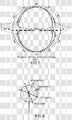
- Figure 1 shows an antenna according to the invention. This antenna is placed on a substrate corresponding to the plane of the sheet. It comprises a slot F with a closed curve form, here a ring. It is dimensioned to operate at a given frequency and fed by a feed line L intersecting the slot F at an excitation point E. More specifically, the perimeter of the annular slot is chosen to be equal to λs, where λs is the guided wavelength in the slot. According to the invention, the slot comprises two short circuits SC, arranged in parallel and diametrically opposed on the annular slot F. They are positioned with respect to the excitation point so as to adjust the impedance at the excitation point. This adjustment is explained hereafter.
- It is known that the coupling conditions are optimal in such antennas when the line is perpendicular to the plane defined by the short circuits, as in this case the physical short circuits coincide with the short circuits induced by the line. In figure 1, when the excitation point is displaced by moving the feed line relative to both short circuits by an angle θ, the impedance at the excitation point is modified.
- The moving of the feed line, for example, simply carried out by a plurality of feed lines arranged around one of the semi-circles of the slot F and activated if necessary when the impedance is required to be modified.
- The invention can also be implemented for applications where the required impedance is fixed and where, a single line is consequently arranged with an angle θ adapted according to the required impedance.
- According to the invention, the coupling conditions between the slot and the line are therefore degraded with respect to the optimal conditions. However, the coupling equation C = E Λ H is not null as long as the excitation point is not on an imposed short circuit point of the slot. Indeed, the field E results from the configuration of slot F and the field H results from the configuration of the line L. By moving the line L by an angle θ, the value of C is therefore reduced without cancelling it out and enables the impedance to be matched. It is thus possible to have variable impedances on the excited half-ring according to the position of the excitation point. The maximum of this impedance is encountered when the coupling conditions are maxi mum, namely, when the line is placed in the middle of the half-ring.
- The field distribution in the half-rings is imposed by the short circuits.
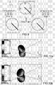
- Figure 2 shows the current distribution and the resulting polarization in the slots of various embodiments of planar antennas according to the invention (Fig. 2a) and according to prior art (Fig. 2b). It is noted in figure 2a that the polarization remains stable by modifying the position of the excitation point whereas it turns with the feed line when the slot does not have any short circuit, as well as shown in figure 2b.
- Hence, the use of at least two short circuits on the slot enables the slot to impose the polarization. Indeed, contrary to what happens for a standard slot not comprising any short circuit or comprising a single short circuit, the direction of linear polarization does not turn according to the position of the excitation point and is imposed by the short circuits. The polarization is therefore perpendicular to the plane of the short circuits, wherever the excitation point is located.
- Figure 3 shows antennas presenting five distinct positions of the excitation point according to the principle of realization shown in figure 1. On these antennas, two diametrically opposed short circuits are arranged on the annular slot. Two half-rings of length Ls/2 are thus facing each other.
- In practice, these antennas are simulated with a dimensioning to operate at 5.8 GHz on a dielectric substrate of type Rogers4003 (Er=3.38, h=0.81 mm). The perimeter of the annular slot must be in the order of the guided wavelength in the slot (Ls) namely a radius of 6.65 mm.
- The impedances of the different antenna are shown in figure 4. The values of the impedances range from 350 Ohms for the position of the line at 90° from the short circuits down to values less than 70 Ohms for the position at 60°, for example. These results confirm the interest of the invention for matching the impedance of the antenna and show the possible extent of the impedance matching.
- Figure 5 shows the four components of the field E in the planes H and V, defined respectively by the short circuits plane and the plane perpendicular to the short circuits plane, for the embodiments of figure 3. It is noted that irrespective of the position of the excitation point, the main component remains omnidirectional (directivity in the order of 3 dB) and the crosspolarization levels are much lower than the copolarization levels (at least 10 dB). This figure confirms that a linear polarization is preserved when there is a shift from the standard maximum coupling position.
- A specific embodiment has been more specifically studied. In this embodiment shown in figure 6, the
antenna 2 comprises two diametrically opposed short circuits and an excitation point at 51° from the reference position. The impedance presented is then around 50 Ohms and can therefore be matched directly on this impedance value. This means that it is unnecessary to extend the line far from the outer side of the slot, as is the case for thestandard antenna 1 also shown in figure 6. Hence, it is noted that with astandard antenna 1 where the line is at 90° to the short circuits plane, the size of the ground plane, with hatching, required to obtain such an impedance is 30x35 mm2 whereas with the invention, as the impedance matching is realized by other means than a longer length of line, the necessary size is only 30x27 mm2. The invention thus provides a saving in compactness. - Figure 6 also shows that the bandwidth at -10 dB is wider. So the bandwidth is 23.1 % for
antenna 2 against 7% for thestandard antenna 1. - Figure 7, showing the radiation patterns, shows that the radiation pattern is however only slightly modified when the excitation point is moved.
- Figure 8 shows a planar antenna according to the invention in which the excitation point E is maintained fixed while the short circuit positions SC1 and SC2 are modified. In this case, the polarization is turned with the short circuits plane.
- The short circuits are implemented using diodes, for example. The diodes can advantageously operate in diametrically opposed pairs.
- Figure 9 shows an embodiment of a planar antenna showing a diversity of polarisation obtained according to the principle of the invention. In this embodiment, four diodes are arranged on the slot at 90° from each other. By switching the diodes opposite each other two by two, two states of linear polarization can be accessed by using a single excitation point. The excitation point position is selected at 45° from one of the short circuit planes to have the same impedance in both polarization states.
- A first polarization state corresponding to a first configuration in which the diodes D1 and D3 are non-conducting, and diodes D2 and D4 conducting. The polarization is then horizontal as shown in the radiation pattern of figure 10a.
- Conversely, the second polarization state corresponds to a second configuration in which the diodes D1 and D3 are conducting, and diodes D2 and D4 non-conducting. The polarization is then vertical as shown in the radiation pattern of figure 10b.
- The description proposed here only comprised two pairs of diodes but the invention enables an antenna with polarization diversity in the order of n to be realized, n being the number of short circuit planes imposed in the slot.
- Hence, the invention can obtain antennas enabling direct matching for any impedance. This means that the antenna is more compact since no impedance transformer is required, that the bandwidth is wider and that the structure presents reduced line loss.
- The invention also enables polarization diversity antenna structures to be obtained. The polarization can be permutated by modifying the short circuit positions without changing the excitation point.
- The invention is not restricted to the embodiments described and those skilled in the art will recognise the existence of diverse variants of embodiments as for example the use of other forms of closed curve slot (squares, polygonals, etc.), the use of diverse slot feed technologies (microstrip, tri-plate, coplanar and co-axial feed technology, etc.), the use of diverse active elements for switching from one state to another (diodes, transistors, MEMs, etc.), the use of the slot in its fundamental mode or higher order modes, the use of a plurality of short circuits not necessarily placed so as to define a diametrical short circuit plane, short circuit pair plane, etc.
Claims (11)
- A planar antenna carried by a substrate comprising a slot (F) in the form of a closed curve dimensioned to operate at a given frequency, supplied by a feed line intersecting the slot (F) at a point known as an excitation point (E), characterized in that at least two short circuits (SC) in parallel on the slot (F) are positioned with respect to the excitation point (E) so as to match the impedance to the excitation point (E) and/or the polarization of the antenna.
- Planar antenna according to claim 1, wherein the short circuits (SC) remaining fixed, the position of the excitation point (E) is modified to modify the impedance.
- Planar antenna according to claim 1, wherein the excitation point (E) remaining fixed, the positions of the short circuits (SC) are modified to modify the polarization.
- Planar antenna according to claim 3, wherein the slot (F) presenting an axis of symmetry perpendicular to the plane in which it is located, four short circuits arranged around the axis at 90° from each other on the slot are activated by pairs of diametrically opposed short circuits to provide the antenna with two separate polarizations.
- Planar antenna according to claim 4, wherein the feed line (L) is arranged at 45° from one of the short circuits (SC).
- Planar antenna according to one of claims 1 to 3, wherein the slot presenting an axis of symmetry perpendicular to the plane on which it is located, the two short circuits (SC) are geometrically opposite on the slot (F) with respect to this axis, thus defining a short circuit plane.
- Planar antenna according to claim 6, wherein both short circuits are situated around the axis at an angle different from 90° with respect to the excitation point.
- Planar antenna according to one of claims 1 to 7, wherein the slot (F) is annular or square or rectangular or polygonal.
- Planar antenna according to one of the previous claims, wherein the short circuits (SC) are realized using switching devices.
- Planar antenna according to claim 9, wherein the switching devices are diodes.
- Method for manufacturing a planar antenna carried by a substrate comprising a slot (F) in the form of a closed curve dimensioned to operate at a given frequency, supplied by a feed line (L) intersecting the slot (F) at a point known as an excitation point (E) , characterized in that it includes the step of positioning at least two short circuits (SC) in parallel on the slot (F), the position with respect to the excitation point (E) of the short circuits being chosen so as to match the impedance to the excitation point (E) and/or the polarization of the antenna.
Applications Claiming Priority (1)
| Application Number | Priority Date | Filing Date | Title |
|---|---|---|---|
| FR0452948A FR2879355A1 (en) | 2004-12-13 | 2004-12-13 | Planar antenna for wireless local area network, has two short-circuits lying parallel to closed curve shaped slot and positioned with respect to excitation point so as to adapt impedance to excitation point and/or polarization of antenna |
Publications (1)
| Publication Number | Publication Date |
|---|---|
| EP1684377A1 true EP1684377A1 (en) | 2006-07-26 |
Family
ID=34952399
Family Applications (1)
| Application Number | Title | Priority Date | Filing Date |
|---|---|---|---|
| EP20050111030 Withdrawn EP1684377A1 (en) | 2004-12-13 | 2005-11-21 | Planar antenna with matched impedance and/or polarization |
Country Status (8)
| Country | Link |
|---|---|
| US (1) | US7420518B2 (en) |
| EP (1) | EP1684377A1 (en) |
| JP (1) | JP2006174463A (en) |
| KR (1) | KR101151916B1 (en) |
| CN (1) | CN1805211B (en) |
| BR (1) | BRPI0505393A (en) |
| FR (1) | FR2879355A1 (en) |
| MX (1) | MXPA05013516A (en) |
Families Citing this family (2)
| Publication number | Priority date | Publication date | Assignee | Title |
|---|---|---|---|---|
| WO2011072844A1 (en) | 2009-12-16 | 2011-06-23 | Adant Srl | Reconfigurable antenna system for radio frequency identification (rfid) |
| DE102010008992A1 (en) * | 2010-02-24 | 2011-08-25 | Siemens Aktiengesellschaft, 80333 | DC high voltage source and particle accelerator |
Citations (3)
| Publication number | Priority date | Publication date | Assignee | Title |
|---|---|---|---|---|
| GB1546571A (en) * | 1976-07-30 | 1979-05-23 | Antenna Specialists Uk Ltd | Antenna |
| JPH05267923A (en) * | 1992-03-19 | 1993-10-15 | Kokusai Kagaku Shinko Zaidan | Slot antenna |
| EP1367673A1 (en) * | 2002-05-31 | 2003-12-03 | Thomson Licensing S.A. | Improvement to planar antennas of the slot type |
Family Cites Families (6)
| Publication number | Priority date | Publication date | Assignee | Title |
|---|---|---|---|---|
| FR1129288A (en) * | 1955-07-28 | 1957-01-17 | Sadir Carpentier | Improvements to directive antennas |
| RU1775757C (en) * | 1991-03-29 | 1992-11-15 | Казанский Авиационный Институт Им.А.Н.Туполева | Polarization switch |
| FR2826512B1 (en) * | 2001-06-22 | 2003-08-29 | Thomson Licensing Sa | COMPACT ANTENNA WITH ANNULAR SLOT |
| FR2833764B1 (en) * | 2001-12-19 | 2004-01-30 | Thomson Licensing Sa | DEVICE FOR RECEIVING AND / OR TRANSMITTING CIRCULARLY POLARIZED ELECTROMAGNETIC SIGNALS |
| JP2004304226A (en) * | 2003-03-28 | 2004-10-28 | Matsushita Electric Ind Co Ltd | Antenna device and radio communication apparatus using the same |
| JP4163632B2 (en) | 2004-01-28 | 2008-10-08 | 日本電波工業株式会社 | Slot line type planar antenna |
-
2004
- 2004-12-13 FR FR0452948A patent/FR2879355A1/en active Pending
-
2005
- 2005-11-21 EP EP20050111030 patent/EP1684377A1/en not_active Withdrawn
- 2005-11-28 US US11/287,999 patent/US7420518B2/en not_active Expired - Fee Related
- 2005-12-01 CN CN2005101272983A patent/CN1805211B/en not_active Expired - Fee Related
- 2005-12-06 BR BRPI0505393-5A patent/BRPI0505393A/en not_active IP Right Cessation
- 2005-12-07 KR KR1020050118744A patent/KR101151916B1/en not_active IP Right Cessation
- 2005-12-13 JP JP2005359280A patent/JP2006174463A/en active Pending
- 2005-12-13 MX MXPA05013516A patent/MXPA05013516A/en active IP Right Grant
Patent Citations (3)
| Publication number | Priority date | Publication date | Assignee | Title |
|---|---|---|---|---|
| GB1546571A (en) * | 1976-07-30 | 1979-05-23 | Antenna Specialists Uk Ltd | Antenna |
| JPH05267923A (en) * | 1992-03-19 | 1993-10-15 | Kokusai Kagaku Shinko Zaidan | Slot antenna |
| EP1367673A1 (en) * | 2002-05-31 | 2003-12-03 | Thomson Licensing S.A. | Improvement to planar antennas of the slot type |
Non-Patent Citations (2)
| Title |
|---|
| HIROSE K ET AL: "DUAL-LOOP SLOT ANTENNA WITH SIMPLE FEED", ELECTRONICS LETTERS, IEE STEVENAGE, GB, vol. 25, no. 18, 31 August 1989 (1989-08-31), pages 1218 - 1219, XP000071688, ISSN: 0013-5194 * |
| PATENT ABSTRACTS OF JAPAN vol. 018, no. 038 (E - 1495) 20 January 1994 (1994-01-20) * |
Also Published As
| Publication number | Publication date |
|---|---|
| KR101151916B1 (en) | 2012-06-01 |
| JP2006174463A (en) | 2006-06-29 |
| US20060152425A1 (en) | 2006-07-13 |
| CN1805211A (en) | 2006-07-19 |
| BRPI0505393A (en) | 2007-03-20 |
| FR2879355A1 (en) | 2006-06-16 |
| KR20060066635A (en) | 2006-06-16 |
| MXPA05013516A (en) | 2006-09-20 |
| US7420518B2 (en) | 2008-09-02 |
| CN1805211B (en) | 2011-07-27 |
Similar Documents
| Publication | Publication Date | Title |
|---|---|---|
| US11283165B2 (en) | Antenna arrays having shared radiating elements that exhibit reduced azimuth beamwidth and increased isolation | |
| US9240634B2 (en) | Antenna and method for steering antenna beam direction | |
| US7369095B2 (en) | Source-antennas for transmitting/receiving electromagnetic waves | |
| JP4205758B2 (en) | Directional variable antenna | |
| US20090140943A1 (en) | Slot antenna for mm-wave signals | |
| US11245179B2 (en) | Antenna and method for steering antenna beam direction for WiFi applications | |
| KR101148970B1 (en) | Wideband omnidirectional radiating device | |
| US10622716B1 (en) | Balanced antenna | |
| US9941584B2 (en) | Reducing antenna array feed modules through controlled mutual coupling of a pixelated EM surface | |
| JP2001036337A (en) | Antenna system | |
| US9525207B2 (en) | Reconfigurable antenna structure with parasitic elements | |
| WO2016079902A1 (en) | Dual band multi-layer dipole antennas for wireless electronic devices | |
| KR102007837B1 (en) | Dual band circular polarization antenna having chip inductor | |
| Zhang et al. | A reconfigurable patch antenna with linear and circular polarizations based on double-ring-slot feeding structure | |
| US7420518B2 (en) | Planar antenna with matched impedance and/or polarization | |
| JP2007124346A (en) | Antenna element and array type antenna | |
| CN116547864A (en) | Dual-polarized substrate integrated 360-degree beam steering antenna | |
| Liu et al. | A wideband planar pattern reconfigurable antenna for IEEE 802.11 ac WLAN applications | |
| Patriotis et al. | Reconfigurable Four-Sector Cube Antenna for IoT Devices | |
| US20180175506A1 (en) | Antenna Device | |
| Rongas et al. | A reconfigurable MuPAR antenna system employing a hybrid beam-forming technique | |
| WO1993000724A1 (en) | Active integrated microstrip antenna | |
| Tang et al. | A scalable compact wideband dual-polarized printed dipole antenna for base station applications |
Legal Events
| Date | Code | Title | Description |
|---|---|---|---|
| PUAI | Public reference made under article 153(3) epc to a published international application that has entered the european phase |
Free format text: ORIGINAL CODE: 0009012 |
|
| AK | Designated contracting states |
Kind code of ref document: A1 Designated state(s): AT BE BG CH CY CZ DE DK EE ES FI FR GB GR HU IE IS IT LI LT LU LV MC NL PL PT RO SE SI SK TR |
|
| AX | Request for extension of the european patent |
Extension state: AL BA HR MK YU |
|
| 17P | Request for examination filed |
Effective date: 20070116 |
|
| 17Q | First examination report despatched |
Effective date: 20070220 |
|
| AKX | Designation fees paid |
Designated state(s): DE FR GB IT |
|
| RAP1 | Party data changed (applicant data changed or rights of an application transferred) |
Owner name: THOMSON LICENSING SA |
|
| STAA | Information on the status of an ep patent application or granted ep patent |
Free format text: STATUS: THE APPLICATION IS DEEMED TO BE WITHDRAWN |
|
| 18D | Application deemed to be withdrawn |
Effective date: 20170601 |