EP1683622A1 - Injection device and method of heating injection device - Google Patents
Injection device and method of heating injection device Download PDFInfo
- Publication number
- EP1683622A1 EP1683622A1 EP04818509A EP04818509A EP1683622A1 EP 1683622 A1 EP1683622 A1 EP 1683622A1 EP 04818509 A EP04818509 A EP 04818509A EP 04818509 A EP04818509 A EP 04818509A EP 1683622 A1 EP1683622 A1 EP 1683622A1
- Authority
- EP
- European Patent Office
- Prior art keywords
- heating
- injection
- heating cylinder
- screw
- cylinder
- Prior art date
- Legal status (The legal status is an assumption and is not a legal conclusion. Google has not performed a legal analysis and makes no representation as to the accuracy of the status listed.)
- Granted
Links
Images



Classifications
-
- B—PERFORMING OPERATIONS; TRANSPORTING
- B29—WORKING OF PLASTICS; WORKING OF SUBSTANCES IN A PLASTIC STATE IN GENERAL
- B29C—SHAPING OR JOINING OF PLASTICS; SHAPING OF MATERIAL IN A PLASTIC STATE, NOT OTHERWISE PROVIDED FOR; AFTER-TREATMENT OF THE SHAPED PRODUCTS, e.g. REPAIRING
- B29C45/00—Injection moulding, i.e. forcing the required volume of moulding material through a nozzle into a closed mould; Apparatus therefor
- B29C45/17—Component parts, details or accessories; Auxiliary operations
- B29C45/72—Heating or cooling
- B29C45/74—Heating or cooling of the injection unit
-
- B—PERFORMING OPERATIONS; TRANSPORTING
- B29—WORKING OF PLASTICS; WORKING OF SUBSTANCES IN A PLASTIC STATE IN GENERAL
- B29C—SHAPING OR JOINING OF PLASTICS; SHAPING OF MATERIAL IN A PLASTIC STATE, NOT OTHERWISE PROVIDED FOR; AFTER-TREATMENT OF THE SHAPED PRODUCTS, e.g. REPAIRING
- B29C45/00—Injection moulding, i.e. forcing the required volume of moulding material through a nozzle into a closed mould; Apparatus therefor
- B29C45/17—Component parts, details or accessories; Auxiliary operations
- B29C45/72—Heating or cooling
-
- B—PERFORMING OPERATIONS; TRANSPORTING
- B29—WORKING OF PLASTICS; WORKING OF SUBSTANCES IN A PLASTIC STATE IN GENERAL
- B29C—SHAPING OR JOINING OF PLASTICS; SHAPING OF MATERIAL IN A PLASTIC STATE, NOT OTHERWISE PROVIDED FOR; AFTER-TREATMENT OF THE SHAPED PRODUCTS, e.g. REPAIRING
- B29C45/00—Injection moulding, i.e. forcing the required volume of moulding material through a nozzle into a closed mould; Apparatus therefor
- B29C45/17—Component parts, details or accessories; Auxiliary operations
- B29C45/46—Means for plasticising or homogenising the moulding material or forcing it into the mould
-
- B—PERFORMING OPERATIONS; TRANSPORTING
- B29—WORKING OF PLASTICS; WORKING OF SUBSTANCES IN A PLASTIC STATE IN GENERAL
- B29C—SHAPING OR JOINING OF PLASTICS; SHAPING OF MATERIAL IN A PLASTIC STATE, NOT OTHERWISE PROVIDED FOR; AFTER-TREATMENT OF THE SHAPED PRODUCTS, e.g. REPAIRING
- B29C45/00—Injection moulding, i.e. forcing the required volume of moulding material through a nozzle into a closed mould; Apparatus therefor
- B29C45/17—Component parts, details or accessories; Auxiliary operations
- B29C45/46—Means for plasticising or homogenising the moulding material or forcing it into the mould
- B29C45/47—Means for plasticising or homogenising the moulding material or forcing it into the mould using screws
- B29C45/50—Axially movable screw
-
- B—PERFORMING OPERATIONS; TRANSPORTING
- B29—WORKING OF PLASTICS; WORKING OF SUBSTANCES IN A PLASTIC STATE IN GENERAL
- B29C—SHAPING OR JOINING OF PLASTICS; SHAPING OF MATERIAL IN A PLASTIC STATE, NOT OTHERWISE PROVIDED FOR; AFTER-TREATMENT OF THE SHAPED PRODUCTS, e.g. REPAIRING
- B29C45/00—Injection moulding, i.e. forcing the required volume of moulding material through a nozzle into a closed mould; Apparatus therefor
- B29C45/17—Component parts, details or accessories; Auxiliary operations
- B29C45/46—Means for plasticising or homogenising the moulding material or forcing it into the mould
- B29C45/53—Means for plasticising or homogenising the moulding material or forcing it into the mould using injection ram or piston
-
- B—PERFORMING OPERATIONS; TRANSPORTING
- B29—WORKING OF PLASTICS; WORKING OF SUBSTANCES IN A PLASTIC STATE IN GENERAL
- B29C—SHAPING OR JOINING OF PLASTICS; SHAPING OF MATERIAL IN A PLASTIC STATE, NOT OTHERWISE PROVIDED FOR; AFTER-TREATMENT OF THE SHAPED PRODUCTS, e.g. REPAIRING
- B29C48/00—Extrusion moulding, i.e. expressing the moulding material through a die or nozzle which imparts the desired form; Apparatus therefor
- B29C48/25—Component parts, details or accessories; Auxiliary operations
- B29C48/255—Flow control means, e.g. valves
- B29C48/2556—Flow control means, e.g. valves provided in or in the proximity of dies
-
- B—PERFORMING OPERATIONS; TRANSPORTING
- B29—WORKING OF PLASTICS; WORKING OF SUBSTANCES IN A PLASTIC STATE IN GENERAL
- B29C—SHAPING OR JOINING OF PLASTICS; SHAPING OF MATERIAL IN A PLASTIC STATE, NOT OTHERWISE PROVIDED FOR; AFTER-TREATMENT OF THE SHAPED PRODUCTS, e.g. REPAIRING
- B29C48/00—Extrusion moulding, i.e. expressing the moulding material through a die or nozzle which imparts the desired form; Apparatus therefor
- B29C48/25—Component parts, details or accessories; Auxiliary operations
- B29C48/36—Means for plasticising or homogenising the moulding material or forcing it through the nozzle or die
- B29C48/475—Means for plasticising or homogenising the moulding material or forcing it through the nozzle or die using pistons, accumulators or press rams
-
- B—PERFORMING OPERATIONS; TRANSPORTING
- B29—WORKING OF PLASTICS; WORKING OF SUBSTANCES IN A PLASTIC STATE IN GENERAL
- B29C—SHAPING OR JOINING OF PLASTICS; SHAPING OF MATERIAL IN A PLASTIC STATE, NOT OTHERWISE PROVIDED FOR; AFTER-TREATMENT OF THE SHAPED PRODUCTS, e.g. REPAIRING
- B29C48/00—Extrusion moulding, i.e. expressing the moulding material through a die or nozzle which imparts the desired form; Apparatus therefor
- B29C48/25—Component parts, details or accessories; Auxiliary operations
- B29C48/36—Means for plasticising or homogenising the moulding material or forcing it through the nozzle or die
- B29C48/50—Details of extruders
- B29C48/505—Screws
- B29C48/53—Screws having a varying channel depth, e.g. varying the diameter of the longitudinal screw trunk
-
- B—PERFORMING OPERATIONS; TRANSPORTING
- B29—WORKING OF PLASTICS; WORKING OF SUBSTANCES IN A PLASTIC STATE IN GENERAL
- B29C—SHAPING OR JOINING OF PLASTICS; SHAPING OF MATERIAL IN A PLASTIC STATE, NOT OTHERWISE PROVIDED FOR; AFTER-TREATMENT OF THE SHAPED PRODUCTS, e.g. REPAIRING
- B29C45/00—Injection moulding, i.e. forcing the required volume of moulding material through a nozzle into a closed mould; Apparatus therefor
- B29C45/17—Component parts, details or accessories; Auxiliary operations
- B29C45/46—Means for plasticising or homogenising the moulding material or forcing it into the mould
- B29C45/53—Means for plasticising or homogenising the moulding material or forcing it into the mould using injection ram or piston
- B29C45/54—Means for plasticising or homogenising the moulding material or forcing it into the mould using injection ram or piston and plasticising screw
-
- B—PERFORMING OPERATIONS; TRANSPORTING
- B29—WORKING OF PLASTICS; WORKING OF SUBSTANCES IN A PLASTIC STATE IN GENERAL
- B29C—SHAPING OR JOINING OF PLASTICS; SHAPING OF MATERIAL IN A PLASTIC STATE, NOT OTHERWISE PROVIDED FOR; AFTER-TREATMENT OF THE SHAPED PRODUCTS, e.g. REPAIRING
- B29C45/00—Injection moulding, i.e. forcing the required volume of moulding material through a nozzle into a closed mould; Apparatus therefor
- B29C45/17—Component parts, details or accessories; Auxiliary operations
- B29C45/46—Means for plasticising or homogenising the moulding material or forcing it into the mould
- B29C45/58—Details
- B29C45/62—Barrels or cylinders
Definitions
- the present invention relates to an injection apparatus and a heating method for an injection apparatus.
- the injection molding apparatus includes a mold apparatus, a mold clamping apparatus, and an injection apparatus.
- the mold clamping apparatus includes a stationary platen and a movable platen, which is advanced and retreated by means of a cylinder for mold clamping.
- the injection apparatus includes a heating cylinder for heating and melting resin, and an injection nozzle attached to the front end of the heating cylinder and adapted to inject the molten resin.
- a screw is disposed within the heating cylinder such that the screw can rotate and can advance and retreat.
- the resin is accumulated forward of the screw, and the screw is retreated to a predetermined position, whereby metering of the resin is performed.
- the resin is heated and melted within the heating cylinder, and due to the pressure of the resin accumulated forward of the screw, the screw is retreated.
- the screw is then advanced by means of the drive unit, so that the resin is injected from the injection nozzle.
- a heating apparatus is attached to the circumference of the heating cylinder so as to heat the heating cylinder to a predetermined temperature.
- an injection apparatus which employs an induction heating apparatus which generate induction current within the heating cylinder itself (see, for example, Patent Document 1).
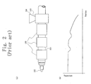
- FIGS. 2(a) and 2(b) are views showing a conventional injection apparatus.
- FIG. 2(a) is a side view of the injection apparatus
- FIG. 2(b) is a graph showing the temperature distribution of a heating cylinder.
- reference numeral 101 denotes a heating cylinder of an injection apparatus
- 102 denotes an injection nozzle attached to the front end of the heating cylinder 101
- 103 denotes a cooling apparatus attached to the heating cylinder 101 in the vicinity of an unillustrated resin supply port
- 104 denotes a resin supply hopper connected to the resin supply port
- 105 denotes an induction-heating-type heating apparatus attached to the periphery of the heating cylinder 101.
- the cooling apparatus 103 is a water jacket through which cooling water flows and which cools the vicinity of the resin supply port of the heating cylinder 101 and a lower end portion of the resin supply hopper 104.
- material resin supplied from the resin supply hopper 104 to the interior of the heating cylinder 101 assumes the form of pellets.
- the resin pellets are fed forward (leftward in FIG. 2(a)) within the heating cylinder 101 by means of an unillustrated screw, which rotates within the heating cylinder 101, while being heated and melted.
- the temperatures at the vicinity of the resin supply port and the lower end portion of the resin supply hopper 104 increase, at least surface portions of the resin pellets melt within the resin supply port and the resin supply hopper 104.
- the resin pellets are bonded together to form aggregates, and/or adhere to the inner surface of the resin supply hopper 104, the inner circumferential surface of the heating cylinder 101, and the flight surface of the screw, etc.
- the resin pellets do not move properly, which makes feeding of the resin toward the front of heating cylinder 101 impossible.
- the cooling apparatus 103 cools the vicinity of the resin supply port of the heating cylinder 101 and the lower end portion of the resin supply hopper 104, whereby the resin pellets are fed in sufficient quantity toward the front of the heating cylinder 101.
- the heating apparatus 105 is divided into a plurality of sections; e.g., three sections, with respect to the axial direction of the heating cylinder 101, wherein each section includes an electromagnetic induction coil.
- each section includes an electromagnetic induction coil.
- an unillustrated thermal insulating material is disposed between the heating apparatus 105 and the heating cylinder 101.
- the heating cylinder 101 is heated over substantially the entire length thereof by means of the heating apparatus 105.
- Patent Document 1 Japanese Patent Application Laid-Open ( kokai ) No. 2003-71893.
- the molten resin may temporarily stagnate within the heating cylinder 101 if the molding is temporarily interrupted. In such a case, the molten resin degrades because of heat, and so-called resin burn may occur. Therefore, when the molding is temporarily interrupted, the temperature of the heating cylinder 101 must be lowered quickly. However, since the thermal insulating material is disposed between the heating apparatus 105 and the heating cylinder 101, the temperature of the heating cylinder 101 cannot be lowered quickly, and occurrence of resin burn cannot be prevented.
- FIG. 2(b) shows a temperature distribution of the heating cylinder of the injection apparatus shown in FIG. 2(a) in the case where the outputs of the respective heating apparatuses 105 are made equal to one another.
- the temperature of the heating cylinder 101 hardly lowers at a portion remote from the cooling apparatus 103. Therefore, at the portion remote from the cooling apparatus 103, it is not necessary to apply a large quantity of heat to the heating cylinder 101 by the induction-heating-type heating apparatus 105.
- the heating apparatuses 105 when the plurality of induction-heating-type heating apparatuses 105 are attached to be close to one another, magnetic interference occurs, and a power supply apparatus for supplying current to the electromagnetic induction coil is broken. Therefore, the heating apparatuses 105 must be attached to the heating cylinder 101 in such a manner that the heating apparatuses 105 are separated from one another by a certain distance. However, in this case, the temperature of the heating cylinder 101 drops between the heating apparatuses 105 as shown in FIG. 2(b).
- An object of the present invention is to solve the above-mentioned problems in the conventional injection apparatus and to provide an injection apparatus and a heating method for an injection apparatus which can uniformly control the temperature of a heating cylinder to a proper value, and which can quickly change the temperature of the heating cylinder.
- the present invention provides an injection apparatus which intermittently feeds forward a resin within a heating cylinder by a screw in accordance with an injection molding cycle, characterized by comprising a cooling apparatus attached to a rear portion of the heating cylinder; and an induction heating apparatus attached to the heating cylinder to be located forward of the cooling apparatus and adjacent to the cooling apparatus.
- the present invention provides another injection apparatus in which the screw advances and retreats within the heating cylinder, and the induction heating apparatus is attached to a portion of the heating cylinder corresponding to at least a feed zone of the screw which is located forward of the cooling apparatus in a state where the screw is retreated.
- the present invention provides still another injection apparatus in which the induction heating apparatus is attached to a portion of the heating cylinder corresponding the feed zone of the screw which is located forward of the cooling apparatus in a state where the screw is advanced.
- the present invention provides still another injection apparatus in which the induction heating apparatus is attached so as to cover at least a portion of the heating cylinder having a length corresponding to a stroke of advancement and retreat of the screw.
- the present invention provides still another injection apparatus in which the induction heating apparatus is attached between the cooling apparatus and a resistance heating apparatus attached to the heating cylinder.
- the present invention provides still another injection apparatus which further includes an injection cylinder and a plunger which advances and retreats within the injection cylinder, wherein the screw rotates when the plunger is located at a retreated position, and the induction heating apparatus is attached to a portion of the heating cylinder located forward of the cooling apparatus and corresponding to a feed zone of the screw.
- the present invention provides a heating method for an injection apparatus which intermittently feeds forward a resin within a heating cylinder by a screw in accordance with an injection molding cycle, the method being characterized by heating a feed zone of the screw by means of an induction heating apparatus attached to a heating cylinder having a cooling apparatus attached to a rear portion thereof, the heating apparatus being located forward of the cooling apparatus and adjacent to the cooling apparatus.
- the present invention provides another heating method for an injection apparatus in which the screw advances and retreats within the heating cylinder.
- the present invention provides still another heating method for an injection apparatus in which the induction heating apparatus is attached between the cooling apparatus and a resistance heating apparatus attached to the heating cylinder.
- the present invention provides still another heating method for an injection apparatus in which the screw includes an injection cylinder and a plunger which advances and retreats within the injection cylinder, and the screw rotates when the plunger retreats.
- the present invention provides still another heating method for an injection apparatus in which a screw advances and retreats within a heating cylinder, the method being characterized by heating a portion having a length corresponding to at least a stroke of advancement and retreat of the screw by means of an induction heating apparatus attached to the heating cylinder having a cooling apparatus attached to a rear portion thereof, the heating apparatus being located forward of the cooling apparatus and adjacent to the cooling apparatus.
- the present invention provides still another heating method for an injection apparatus in which the induction heating apparatus is attached between the cooling apparatus and a resistance heating apparatus attached to the heating cylinder.
- the injection apparatus of the present invention is an injection apparatus which intermittently feeds forward a resin within a heating cylinder by a screw in accordance with an injection molding cycle and which comprises a cooling apparatus attached to a rear portion of the heating cylinder, and an induction heating apparatus attached to the heating cylinder to be located forward of the cooling apparatus and adjacent to the cooling apparatus.
- the temperature of the heating cylinder can be uniformly controlled to a proper value, and the temperature of the heating cylinder can be changed quickly.
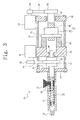
- FIG. 3 is a schematic sectional view showing the structure of an injection apparatus according to a first embodiment of the present invention.
- reference numeral 10 denotes an injection apparatus according to the present embodiment, which is used in an injection molding machine, which is a molding machine of one type.
- the injection molding machine includes an unillustrated mold clamping apparatus, and moves a movable mold in relation to a stationary mold, to thereby perform mold closing, mold clamping, and mold opening.
- the mold clamping apparatus which may be of any type, includes a stationary platen fixed to an unillustrated frame, and a movable platen disposed in opposition to the stationary platen such that it can advance and retreat along unillustrated tie bars. Through advancing and retreating the movable platen, a movable mold attached to the movable platen is moved in relation to a stationary mold attached to the stationary platen so as to perform mold closing, mold clamping, and mold opening.
- a toggle support is disposed on the frame to be located rear of the movable platen; i.e., on the side opposite the stationary platen.
- a toggle drive apparatus attached to the toggle support drives a toggle mechanism so as to advance and retreat the movable platen.
- the above-mentioned tie bars are disposed to extend between the stationary platen and the toggle support.
- the toggle drive apparatus includes a mold open/close motor (drive source) 67, which will be described later; and an unillustrated motion direction conversion apparatus which is composed of a ball-screw mechanism or the like and which converts rotational motion of the mold open/close motor 67 to reciprocal motion so as to advance and retreat a drive shaft to thereby activate the toggle mechanism.
- an ejector apparatus is attached to the movable platen. After completion of mold opening, the ejector apparatus causes an ejector pin to project from the cavity wall of the movable mold so as to eject a molded product adhering to the cavity wall.
- the ejector apparatus includes an ejector motor (drive source) 66, which will be described later; and an unillustrated motion direction conversion apparatus which is composed of a ball-screw mechanism or the like and which converts rotational motion of the ejector motor 66 to reciprocal motion so as to advance and retreat the ejector pin.
- the injection apparatus 10 On the rear side of the stationary platen; i.e., on the side opposite the movable platen, the injection apparatus 10 is movably attached to the frame. Notably, the injection apparatus 10 is advanced and retreated in relation to the stationary platen by means of an unillustrated injection-apparatus moving mechanism, and can be advanced (moved leftward in FIG. 3) for nozzle touching.
- the injection apparatus 10 includes a heating cylinder 11 which has an injection nozzle 13 at the front end (left end in FIG. 3) thereof.
- the injection apparatus 10 is configured to intermittently feed forward resin within the heating cylinder 11 by means of a screw 12 in accordance with an injection molding cycle.
- a resin supply hopper 16 is attached to the heating cylinder 11 in order to supply to the interior of the heating cylinder 11 a material resin 17 in the form of grains, pellets, powder, or the like.
- the screw 12 is disposed within the heating cylinder 11 such that the screw 12 can rotate and can advance and retreat; i.e., can move forward and backward.
- the rear end (right end in FIG. 3) of the heating cylinder 11 is attached to a front injection support 31 of the injection apparatus, which rotates the screw 12 within the heating cylinder 11, and advances and retreats the screw 12 (moves the screw 12 leftward and rightward in FIG. 3) within the heating cylinder 11.
- the injection apparatus includes a rear injection support 32 separated from the front injection support 31 by a predetermined distance.
- Guide bars 33 are disposed to extend between the front and rear injection supports 31 and 32.
- a pressure plate 34 is supported by the guide bards 33 such that the pressure plate 34 can advance and retreat along the guide bars 33.
- the front and rear injection supports 31 and 32 are slidably attached to the frame via an unillustrated slide apparatus.
- a drive shaft 35 is coupled with the rear end of the screw 12, and rotatably supported by bearings 36 and 37 to be rotatable in relation to the pusher plate 34.
- an electric metering motor 41 which serves as a first drive means, is disposed; and a first rotation transmission means, composed of pulleys 42 and 43 and a timing belt 44, is disposed between the metering motor 41 and the drive shaft 35. Accordingly, the screw 12 can be rotated in the regular or reverse direction through drive of the metering motor 41.
- the electric metering motor 41 is used as the first drive means; however, a hydraulic motor may be used in place of the electric metering motor 41.
- a ball screw 47 composed of a ball screw shaft 45 and a ball nut 46 in mutual screw engagement, is disposed on the rear side (right-hand side in FIG. 3) of the pressure plate 34.
- the ball screw 47 constitutes a motion direction conversion apparatus which converts rotational motion to reciprocal motion.
- the ball screw shaft 45 is supported by a bearing 48 to be rotatable in relation to the rear injection support 32.
- the ball nut 46 is secured to the pressure plate 34 via a plate 51 and a load cell 52.
- an injection motor 53 which serves as a second drive means, is disposed; and a second rotation transmission means, composed of pulleys 54 and 55 and a timing belt 56, is disposed between the injection motor 53 and the ball screw shaft 45.
- the injection motor 53 is used as the second drive means; however, an injection cylinder may be used in place of the injection motor 53.
- FIG. 1 is a sectional view showing the structure of the main portion of the injection apparatus according to the first embodiment of the present invention, with the screw advanced.
- the screw 12 includes a main body portion 12a, and a larger-diameter portion 12b connected to the rear end of the main body portion 12a.
- the above-described drive shaft 35 is connected to the rear end of the larger-diameter portion 12b.
- the main body portion 12a includes a flight 14 spirally formed on the outer circumference thereof, and a spiral grove 15 is formed by the flight 14.
- a screw head 12c is provided on the front side (on the left side in FIG. 1) of the main body portion 12a, and is connected to the main body portion 12a via a smaller-diameter connection portion 12d.
- the heating cylinder 11 has a resin supply port (molding material supply port) 11a, which is an opening formed in a rear portion of the heating cylinder 11.
- the lower end of the resin supply hopper 16 is connected to the resin supply port 11a, whereby the material resin 17 is supplied from the resin supply hopper 16 to the interior of the heating cylinder 11 via the resin supply port 11a.
- a cooling apparatus 23 is attached to the outer circumference of the heating cylinder 11.
- the cooling apparatus 23 is a water jacket having a flow passage 23a formed therein, and a cooling medium such as cooling water flows through the flow passage 23a.
- the cooling apparatus 23 cools the vicinity of the resin supply port 11a of the heating cylinder 11 and a lower end portion of the resin supply hopper 16.
- the resistance heating apparatus 22 is composed of a first band heater 22a, a second band heater 22b, a third band heater 22c, and a fourth band heater 22d, which are arranged along the axial direction of the heating cylinder 11.
- the third band heater 22c and the fourth band heater 22d are attached to a larger-diameter portion 13a and a smaller-diameter portion 13b, respectively, of the injection nozzle 13 at the front end of the heating cylinder 11.
- the resistance heating apparatus 22 may be a single heating section or may be divided into any number of heating sections, and may be attached to any portion.
- the third band heater 22c and the fourth band heater 22d may be integrated into a single heater, or the third band heater 22c or the fourth band heater 22d may be omitted.
- the first through fourth band heaters 22a to 22d are described collectively, they are referred to as the "resistance heating apparatus 22."
- the induction heating apparatus 21 is attached to a portion of the heating cylinder 11, the portion being located frontward of the cooling apparatus 23 and adjacent to the cooling apparatus 23.
- the cooling apparatus 23 is disposed to be close to the induction heating apparatus 21.
- the induction heating apparatus 21 includes an electromagnetic induction coil. Through supply of high-frequency current to the electromagnetic induction coil, induction current is generated within the heating cylinder 11 and the heating cylinder 11 is heated by the induction current.
- an unillustrated thermal insulating material is interposed between the induction heating apparatus 21 and the heating cylinder 11.
- the induction heating apparatus 21 itself may have a thermal insulating material at portions which come into contact with the outer circumference of the heating cylinder 11.
- the resistance heating apparatus 22 includes a resistance heating line, or lead, which assumes a wire-like shape or a planar shape. Through supply of current to the lead, the lead generates heat to thereby heat the heating cylinder 11. In this manner, the heating cylinder 11 can be heated to a predetermined temperature through supply of electricity to the induction heating apparatus 21 and the resistance heating apparatus 22.
- the induction heating apparatus 21 may be divided into a plurality of sections along the axial direction of the heating cylinder 11.
- a conductor serving as a protective member may be provided between the sections of the induction heating apparatus 21, whereby the sections can be attached to be close to one another.
- the conductor is attached to the outer circumference of the thermal insulating material, and assumes the form of a split flange which enables maintenance to be performed in a state where the induction heating apparatus 21 is attached to the heating cylinder 11. Since the protective member is provided between the sections of the induction heating apparatus 21, each including an electromagnetic induction coil, the protective member can function as a magnetic shield. Accordingly, even when the sections of the induction heating apparatus 21 are attached to be close to one another, magnetic interference does not occur.
- FIG. 1 shows a state in which the screw 12 is located at the most advanced position.
- a feed zone (supply portion) Z1 to which the material resin 17 is supplied from the resin supply port 11a
- a compression zone (compression portion) Z2 in which the supplied material resin 17 is melted while being compressed
- a metering zone (metering portion) Z3 in which a certain amount of the melted resin or molten resin 17a is metered, are sequentially formed on the main body portion 12a of the screw 12, from a position adjacent to the larger-diameter portion 12b toward the front.
- the outer diameter of the bottom of the groove 15; i.e., the main body portion 12a, is set to be relatively small in the feed zone Z1, to gradually increase in the compression zone Z2 from the rear to the front, and to be relatively large in the metering zone Z3. Accordingly, the clearance between the inner circumferential surface of the heating cylinder 11 and the outer circumferential surface of the main body portion 12a is relatively large in the feed zone Z1, gradually decreases in the compression zone Z2 from the rear to the front, and is relatively small in the metering zone Z3.
- the material resin 17 within the hopper 16 is supplied to the feed zone Z1 via the resin supply port 11a, and is caused to advance (move leftward in FIG. 1) within the groove 15. With this, the screw 12 is caused to retreat (move rightward in FIG. 1), whereby the molten resin 17a is accumulated forward of the screw head 12c.
- the resin within the groove 15 assumes a solid form such as grains, pellets, or powder, in the feed zone Z1, is half melted in the compression zone Z2, and is completely melted and becomes the molten resin 17a in the metering zone Z3.
- the outer circumferential surface of the main body portion 12a and the inner circumferential surface of the heating cylinder 11 are of the same roughness, even when the screw 12 is rotated in a metering step, the material resin 17 within the groove 15 is rotated together with the screw 12, and does not advance. Therefore, in general, the inner circumferential surface of the heating cylinder 11 is processed to be rougher than the outer circumferential surface of the main body portion 12a.
- the screw 12 is advanced in an injection step, the molten resin 17a accumulated forward of the screw head 12c is injected from a nozzle hole 13c of the injection nozzle 13. At this time, the molten resin 17a accumulated forward of the screw head 12c may flow in the reverse direction.
- a reverse-flow prevention device composed of a reverse-flow prevention ring 12e and a seal ring 12f is disposed around the connection portion 12d.
- FIG. 4 is a diagram showing the configuration of the controller of the injection apparatus according to the first embodiment of the present invention.
- reference numeral 61 denotes a single-phase AC power source for supplying current to the resistance heating apparatus 22.
- the AC power source 61 supplies current to the first band heater 22a, the second band heater 22b, the third band heater 22c, and the fourth band heater 22d via a power supply line 61a.
- a main switch 61b is interposed in the power supply line 61a.
- a first on-off switch 63a for controlling current supplied to the first band heater 22a, a second on-off switch 63b for controlling current supplied to the second band heater 22b, and a third on-off switch 63c for controlling current supplied to the third and fourth band heaters 22c and 22d are disposed in corresponding branch lines branched from the power supply line 61a.
- the third and fourth band heaters 22c and 22d are formed integrally.
- the third and fourth band heaters 22c and 22d may be formed individually.
- currents supplied to these heaters may be individually controlled through provision of independent on-off switches.
- the first on-off switch 63a, the second on-off switch 63b, and the third on-off switch 63c are semiconductor switches formed of, for example, thyristors, and their operations are individually controlled by a heating control section 74 to be described later.
- Reference numeral 62 denotes a three-phase AC power source for supplying current to various motors, etc., via a three-phase power supply line 62a.
- the current is converted to direct current by means of a converter 64, and the direct current is supplied via a power supply line 64a to a first motor inverter 65a, a second motor inverter 65b, a third motor inverter 65c, and a fourth motor inverter 65d.
- switches 62b and 64b are interposed in the three-phase power supply line 62a and the power supply line 64a, respectively.
- the first motor inverter 65a controls current supplied to the ejector motor 66; the second motor inverter 65b controls current supplied to the mold open/close motor 67; the third motor inverter 65c controls current supplied to the metering motor 41; and the fourth motor inverter 65d controls current supplied to the injection motor 53.
- each of the ejector motor 66, the mold open/close motor 67, the metering motor 41, and the injection motor 53 is a servomotor.
- each of the first through fourth motor inverters 65a to 65d is an inverter which converts direct current to alternating current of an arbitrary frequency; and their operations are individually controlled by a motor control section 73 to be described later.
- the direct current from the converter 64 is controlled by means of an IH inverter 68, and is supplied to the electromagnetic induction coil of the induction heating apparatus 21.
- the operation of the IH inverter 68 is controlled by the heating control section 74.
- Reference numeral 71 denotes a sequence control section which controls the entire operation of the injection apparatus 10.
- Reference numeral 72 denotes a display setting unit which is connected to the sequence control section 71 and which includes display devices such as various meters, lamps, a CRT, a liquid crystal display, and an LED (light emitting diode) display, and input devices such as various buttons, a keyboard, a joystick, a mouse, and a touch panel.
- An operator of the injection apparatus 10 operates the input devices, while viewing the displays of the display devices, so as to perform various settings.
- the motor control section 73 and the heating control section 74 are connected to the sequence control section 71.
- the motor control section 73 controls the first through fourth motor inverters 65a to 65d in accordance with instructions from the sequence control section 71 to thereby control the operations of the ejector motor 66, the mold open/close motor 67, the metering motor 41, and the injection motor 53.
- the heating control section 74 includes a temperature input section 74a, a control/computation section 74b, and an output control section 74c.
- the heating control section 74 controls the operations of the first on-off switch 63a, the second on-off switch 63b, the third on-off switch 63c, and the IH inverter 68 in accordance with instructions from the sequence control section 71 to thereby control the operations of the first through fourth band heaters 22a to 22d, as well as the operation of the induction heating apparatus 21.
- a first temperature detector 75a is provided on a portion of the heating cylinder 11 where the cooling apparatus 23 is attached.
- a second temperature detector 75b is provided on a portion of the heating cylinder 11 where the induction heating apparatus 21 is attached.
- a third temperature detector 75c is provided on a portion of the heating cylinder 11 where the first band heater 22a is attached.
- a fourth temperature detector 75d is provided on a portion of the heating cylinder 11 where the second band heater 22b is attached.
- a fifth temperature detector 75e is provided on a portion of the heating cylinder 11 where the third and fourth band heaters 22c and 22d are attached.
- the first through fifth temperature detectors 75a to 75e each of which is a temperature sensor such as a thermistor or a thermocouple, detect the temperature of the heating cylinder 11, and input the detected temperature to the temperature input section 74a.
- the control/computation section 74b calculates control values for rendering the temperatures at the respective portions of the heating cylinder 11 coincident with the corresponding target temperatures.
- the output control section 74c controls the operations of the first on-off switch 63a, the second on-off switch 63b, the third on-off switch 63c, and the IH inverter 68, to thereby control the quantities of heat generated by the first through fourth band heaters 22a to 22d and the induction heating apparatus 21, such that the temperatures at the respective portions of the heating cylinder 11 coincide with the corresponding target temperatures.
- each of the sequence control section 71, the motor control section 73, and the heating control section 74 is a computer which includes computation means such as a CPU or MPU, storage means such as a magnetic disc, semiconductor memory, etc., and an input/output interface.
- the sequence control section 71, the motor control section 73, and the heating control section 74 may be configured independently of one another or may be portions of an single, integrally-formed controller. Alternatively, these sections may be integrated with another controller. For example, each of these sections may be one of a plurality of control systems created within a large-scale computer.
- FIG. 5 is a sectional view showing the structure of the main portion of the injection apparatus according to the first embodiment of the present invention, with the screw retreated.
- the metering motor 41 rotates, and the pulley 42 rotates. Rotation of the pulley 42 is transmitted to the drive shaft 35 via the timing belt 44 and the pulley 43.
- the screw 12 connected to the drive shaft 35 rotates in the regular direction.
- the material resin 17 within the resin supply hopper 16 is supplied to the feed zone Z1 via the resin supply port 11a and is caused to advance within the groove 15.
- the material resin 17, advancing within the groove 15, receives heat from the heating cylinder 11 heated to a predetermined temperature, and receives shearing energy, so that the material resin 17 is heated and melted.
- the material resin 17 is half-melted in the compression zone Z2, and is completely melted and becomes the molten resin 17a in the metering zone Z3. Since the molten resin 17a is accumulated forward of the screw head 12c, due to the pressure of the accumulated molten resin 17a, the screw 12 is retreated to the position shown in FIG. 5.
- the injection nozzle 13 at the front end of the heating cylinder 11 is inserted into the nozzle insertion hole of the unillustrated stationary platen, and pressed against the stationary mold for nozzle touching.
- the injection motor 53 then rotates, and the pulley 54 rotates. Rotation of the pulley 54 is transmitted to the ball screw shaft 45 via the timing belt 56 and the pulley 55. With rotation of the ball screw shaft 45, the ball nut 46 and the pressure plate 34 advance, whereby the screw 12 is advanced.
- the toggle mechanism is operated through rotation of the mold open/close motor 67, and thus, the movable platen and the movable mold are advanced to perform mold closing, whereby the mold surface of the movable mold comes into contact with the mold surface of the stationary mold. Therefore, a cavity space having a shape corresponding to an article to be molded is formed by the cavity of the stationary mold and the cavity of the movable mold.
- the screw 12 is advanced in this state, the molten resin 17a accumulated on the front side of the screw 12c is injected from the nozzle hole 13c of the injection nozzle 13, and is charged into the cavity space via a sprue formed in the stationary mold.
- the mold apparatus may include a single cavity or a plurality of cavities. In the case where the mold apparatus includes a plurality of cavities, a plurality of articles can be molded through a single-shot molding process.
- the molten resin 17a contains incompletely melted resin; and when the temperature of the heating cylinder 11 is excessively high, the molten resin 17a thermally decomposes or generates gas.
- the proper temperatures of the heating cylinder 11 and the injection nozzle 13 change depending on the type of resin, the shape of articles to be molded, the molding cycle (molding speed), and the like.
- the first through fifth temperature detectors 75a to 75e detect temperatures of the heating cylinder 11, and the heating control section 74 controls the quantities of heat generated by the first through fourth band heaters 22a to 22d and the induction heating apparatus 21 on the basis of the differences between the detected temperatures of the heating cylinder 11 and the target temperatures of the heating cylinder 11 received from the sequence control section 71.
- the temperatures of the heating cylinder 11 can be controlled to proper values.
- the temperature conditions required at the respective portions of the heating cylinder 11 change. That is, generally the entire portion of the heating cylinder 11 must be maintained at a relatively high temperature so as to sufficiently heat the material resin 17. In contrast, the portion in the vicinity of the resin supply port 11a of the heating cylinder 11 must be maintained at a relatively low temperature so as to prevent melting of the surfaces, etc. of the material resin 17 in the solid form within the resin supply port 11a and the resin supply hopper 16, to thereby prevent formation of aggregates or adhesion to the inner surface of the resin supply hopper 16, the inner circumferential surface of the heating cylinder 11, the surface of the screw 12, etc.
- the cooling apparatus 23 is attached to the outer circumference of the heating cylinder 11 so as to cool the vicinity of the resin supply port 11a of the heating cylinder 11 and the lower end portion of the resin supply hopper 16.
- the temperature of that portion lowers.
- the cooling apparatus 23 takes a large quantity of heat out of a portion of the heating cylinder 11 located forward of the cooling apparatus 23 and adjacent thereto, the temperature greatly lowers at that portion.
- the above-mentioned portion corresponds to the feed zone Z1 of the screw 12 and is close to the compression zone Z2 thereof. Therefore, the material resin 17 must be sufficiently heated at the above-mentioned portion.
- the induction heating apparatus 21 is attached to the outer circumference of a portion of the heating cylinder 11, the portion being located forward of the cooling apparatus 23 and adjacent thereto.
- the induction heating apparatus 21 generates induction current within the heating cylinder 11 through supply of high-frequency current to the electromagnetic induction coil contained therein, to thereby heat the heating cylinder 11. Therefore, theoretically, a large quantity of heat can be applied to the heating cylinder 11.
- the induction heating apparatus 21 is attached to be very close to the cooling apparatus 23. Therefore, the induction heating apparatus 21 can maintain at a predetermined temperature the portion located forward of the cooling apparatus 23 and adjacent thereto.
- the first through fourth band heaters 22a to 22d which constitute the resistance heating apparatus 22, are attached to the portion other than the portion located forward of the cooling apparatus 23 and adjacent thereto; i.e.,. a portion remote from the cooling apparatus 23. Since the cooling apparatus 23 does not take a large quantity of heat from a portion remote from the cooling apparatus 23, the temperature does not decrease. Therefore, even the resistance heating apparatus 22, which cannot apply a large quantity of heat to the heating cylinder 11 within a short period of time as compared with the induction heating apparatus 21, can maintain the portion remote from the cooling apparatus 23 at a predetermined temperature.
- the plurality of sections (band heaters) of the resistance heating apparatus 22 are attached to be close to one another, magnetic interference does not occur, unlike the case of the induction heating apparatus 21. Further, even when the resistance heating apparatus 22 is attached to be close to the induction heating apparatus 21, magnetic interference does not occur. Therefore, the plurality of sections (band heaters) of the resistance heating apparatus 22 and the induction heating apparatus 21 can be attached in such a manner that they are located close to one another and no gap is formed therebetween with respect to the axial direction of the heating cylinder 11. Accordingly, the heating cylinder 11 can be heated while its temperature is properly controlled along the axial direction of the heating cylinder 11.
- the temperature of the heating cylinder 11 can be properly controlled along the axial direction of the heating cylinder 11, so that no dip arises in the temperature of the heating cylinder 11 between the sections of the resistance heating apparatus 22 or between the resistance heating apparatus 22 and the induction heating apparatus 21.
- the temperature of the heating cylinder 11 must be lowered when the temperature of the heating cylinder 11 has exceeded a predetermined temperature, when the resin is exchanged with a resin having a lower melting point at the time of resin exchange, or when the molten resin 17a temporarily stagnates within the heating cylinder 11 because of temporary interruption of the molding process. In such a case, the only required action is to stop the supply of electricity to the resistance heating apparatus 22. Since the resistance heating apparatus 22 is high in heat radiation performance, the temperature of the portion remote from the cooling apparatus 23 lowers quickly.
- the induction heating apparatus 21 is low in heat radiation performance, because in order to protect the electromagnetic induction coil from heat of the heating cylinder 11, the induction heating apparatus 21 must have a thermal insulating material and/or a thermal insulating material must be provided between the induction heating apparatus 21 and the heating cylinder 11.
- the resistance heating apparatus 22 is high in heat radiation performance, because the resistance heating apparatus 22 is not required to have a thermal insulating material and no thermal insulating material is required to be provided between the resistance heating apparatus 22 and the heating cylinder 11.
- the induction heating apparatus 21, which is low in heat radiation performance is attached to the portion located forward of the cooling apparatus 23 and adjacent thereto, the temperature of that portion drops quickly, because the cooling apparatus 23 takes heat out of that portion.
- the resistance heating apparatus 22 which is high in cooling speed, is used, so that the temperature can be lowered quickly.
- the temperatures of the compression zone Z2 and the metering zone Z3 can be lowered quickly.
- the temperature of the heating cylinder 11 can be properly controlled. Further, the working time for resin exchange can be shortened. In addition, even when the molten resin 17a temporarily stagnates within the heating cylinder 11, degrading or burning of the molten resin 17a can be prevented.
- the induction heating apparatus 21 is disposed at a portion corresponding to at least the feed zone Z1 of the screw 12, which is located forward of the cooling apparatus 23 in a state where the screw 12 is retreated as shown in FIG. 5. By virtue of this configuration, a large quantity of heat can be applied to the heating cylinder 11 at that portion, so that the material resin 17 supplied from the resin supply port 11a to the feed zone Z1 can be heated sufficiently.
- the induction heating apparatus 21 desirably has a size to cover a portion corresponding to the feed zone Z1 of the screw 12, which is located forward of the cooling apparatus 23 in a state where the screw 12 is advanced as shown in FIG. 1.
- a large quantity of heat can be applied to the heating cylinder 11 at the entire portion corresponding to the feed zone Z1, so that the material resin 17 can be heated sufficiently in the entire feed zone Z1 of the screw 12 located forward of the cooling apparatus 23.
- the screw 12 is moved from the retreated state (state after completion of metering) as shown in FIG. 5 to the advanced state (after completion of injection) as shown in FIG. 1, the material resin 17 is supplied to the feed zone Z1, and the supplied material resin 17 takes heat from the heating cylinder 11 in that area.
- the material resin 17 in the feed zone Z1 can be heated sufficiently. Further, in the state where the screw 12 is retreated, since the distance between the resin supply port 11a and the compression zone Z2; i.e., the effective length of the feed zone Z1, decreases, a rear portion of the compression zone Z2 can be heated accordingly, so that material resin 17 can be heated sufficiently.
- the induction heating apparatus 21 desirably has a size to cover at least a portion having a length corresponding to the stroke over which the screw 12 advances and retreats.
- the material resin 17 is supplied from the resin supply port 11a to the feed zone Z1. Therefore, the temperature of the material resin 17 may drop in the portion having a length corresponding to the stroke.
- the induction heating apparatus 21 covers the portion having a length corresponding to the stroke, the material resin 17 can be heated sufficiently. Therefore, even at the portion having a length corresponding to the stroke, the temperature of the material resin 17 does not drop. Accordingly, high-cycle molding becomes possible, and the molding efficiency of the injection molding machine is improved.
- the injection nozzle 13 attached to the front end of the heating cylinder 11 is equipped with the resistance heating apparatus 22, which is smaller in size than the induction heating apparatus 21.
- the resistance heating apparatus 22 is desired. This eliminates the necessity of providing a large space around the injection nozzle 13 for providing a device for heating the injection nozzle 13. As a result, the nozzle insertion hole of the unillustrated stationary platen can be made smaller.
- the induction heating apparatus 21 is attached to the outer circumference of a portion of the heating cylinder 11, the portion being located forward of the cooling apparatus 23 and adjacent thereto. Therefore, the portion of the heating cylinder 11 located forward of the cooling apparatus 23 and adjacent thereto can be heated by means of the induction heating apparatus 21, which can apply a large quantity of heat to the heating cylinder 11, whereby that portion can be maintained at a predetermined temperature. Accordingly, the temperature of the heating cylinder 11 can be uniformly controlled to a proper value.
- FIG. 6 is a schematic sectional view showing the structure of an injection apparatus according to the second embodiment of the present invention.
- the injection apparatus 10 is a so-called preplasticating injection apparatus, and includes an injection cylinder 91; a plunger (injection member) 92 disposed in the injection cylinder 91 such that the plunger 92 can advance and retreat (can move leftward and rightward in FIG. 6); and a plunger drive apparatus (drive section for metering and injection) 93 for advancing and retreating the plunger 92.
- the injection apparatus 10 intermittently feeds forward resin within a heating cylinder 11 by means of a screw 12 in accordance with the molding cycle.
- the heating cylinder 11 is connected to a predetermined portion of the injection cylinder 91 via a communication pipe 83 having a communication passage 84 formed therein, and obliquely extends upward from the connection position.
- the heating cylinder 11 supplies a molten resin 17a to the interior of the injection cylinder 91 via the communication passage 84.
- an induction heating apparatus 21 is attached to the outer circumference of a portion of the heating cylinder 11, the portion being located forward of a cooling apparatus 23 and corresponding to the feed zone Z1 of the screw 12.
- a valve member (open-close valve) 85 is interposed in the communication passage 84 so as to control the supply of the molten resin 17a to the heating cylinder 11.
- the valve member 85 can be opened and closed through drive of an unillustrated actuator by the above-described controller so as to open or block the communication passage 84 between the heating cylinder 11 and the injection cylinder 91, or adjust the degree of opening, to thereby control the flow rate of the molten resin 17a passing through the communication passage 84.
- a ball valve is used as the valve member 85.
- a needle valve, a slide mechanism, or the like can be used in place of the ball valve.
- the screw 12 is prevented from advancing or retracting within the heating cylinder 11. That is, the screw 12 is disposed within the heating cylinder 11 such that the screw 12 can rotate but cannot advance or retreat.
- a screw drive motor (screw drive apparatus) 81 for rotating the screw 12 within the heating cylinder 11 is attached to the rear end (right-hand end in FIG. 6) of the heating cylinder 11. Operation of the screw drive motor 81 is controlled by the above-mentioned controller.
- the screw 12 is coupled with the output shaft of the screw drive motor 81 via a coupler 82.
- An injection nozzle 13 is attached to the front end (left-hand end in FIG. 6) of the injection cylinder 91.
- the above-mentioned fourth band heater 22d is omitted.
- the fourth band heater 22d may be attached to the injection nozzle 13.
- the above-mentioned resistance heating apparatus 22 further includes a fifth band heater 22e and a sixth band heater 22f, which are attached to the outer circumference of the injection cylinder 91.
- Supply of electricity to the fifth band heater 22e and the sixth band heater 22f is controlled by the above-described controller.
- the injection cylinder 91 can be heated to a predetermined temperature.
- the fifth band heater 22e and the sixth band heater 22f may be integrated into a single heater, or the fifth band heater 22e or the sixth band heater 22f may be omitted.
- the rear end (right-hand end in FIG. 6) of the plunger 92 is connected via a coupler 94 to the output shaft of the plunger drive apparatus 93 disposed on the rear side (right-hand side in FIG. 6) of the injection cylinder 91. Operation of the plunger drive apparatus 93 is controlled by the above-described controller.
- the plunger 92 before start of a metering step, the plunger 92 is placed at a metering start position, which is a rearward retracted position within the injection cylinder 91. Further, the controller drives the actuator such that a predetermined degree of opening is realized by the valve member 85, and the molten resin 17a flows through the communication passage 84 at a predetermined flow rate.
- the screw drive motor 81 operates to thereby rotate the screw 12 with the plunger 92 being located at the metering start position. As a result, the material resin 17 within the resin supply hopper 16 is supplied into the heating cylinder 11.
- the supplied material resin 17 advances within the groove 15 with rotation of the screw 12, so that the material resin 17 moves from a feed zone Z1 to a compression zone Z2, and then reaches a metering zone Z3.
- the material resin 17 is half-melted in the compression zone Z2, and is completely melted and becomes the molten resin 17a in the metering zone Z3.
- the molten resin 17a is supplied to the interior of the injection cylinder 91 via the communication passage 84, and is accumulated forward of the plunger 92.
- the material resin 17 tends to move forward within the heating cylinder 11 with rotation of the screw 12.
- the flow rate of the molten resin 17a at the communication passage 84 is restricted by means of the valve member 85, whereby the molten resin 17a is throttled.
- a back pressure corresponding to the degree of opening can be applied to the molten resin 17a within the heating cylinder 11, so that the density of the plasticized resin; i.e., the molten resin 17a, can be made uniform.
- the quality of molded articles can be improved.
- the controller drives the actuator so as to close the valve member 85, to thereby shut off the communication passage 84, and stops the operation of the screw drive motor 81 to thereby stop the rotation of the screw 12.
- the injection nozzle 13 at the front end of the heating cylinder 11 is inserted into the nozzle insertion hole of an unillustrated stationary platen, and pressed against a stationary mold for nozzle touching.
- the controller then operates the plunger drive apparatus 93 so as to advance the plunger 92 toward the advancement limit position.
- the molten resin 17a accumulated on the front side of the plunger 92 within the heating cylinder 11 is injected from a nozzle hole 13c of the injection nozzle 13, and is charged into the cavity space via a sprue formed in the stationary mold.
- the controller stops the operation of the plunger drive apparatus 93 so as to stop the plunger 92, to thereby complete the injection step. Subsequently, the controller operates the plunger drive apparatus 93 so as to retreat the plunger 92 to the metering start position for the next shot.
- the induction heating apparatus 21 is attached to the heating cylinder 11 at a portion located forward of the cooling apparatus 23 and corresponding to the feed zone Z1 of the screw 12.
- the portion of the heating cylinder 11 corresponding to the feed zone Z1 of the screw 12 can be heated by means of the induction heating apparatus 21, which can apply a large quantity of heat to the heating cylinder 11, whereby that portion can be maintained at a predetermined temperature. Accordingly, the temperature of the heating cylinder 11 can be uniformly controlled to a proper value.
- the injection molding machine is of a horizontal type in which the movable platen moves in a lateral direction (horizontal direction).
- the injection apparatus and the heating method for an injection apparatus of the present invention can be applied to a vertical-type injection molding machine in which the movable platen moves in a vertical direction.
- the injection apparatus and the heating method for an injection apparatus of the present invention can be applied not only to injection molding machines, but also to other forming machines such as die cast machines and IJ sealing presses.
- the present invention can be applied to injection apparatuses and heating methods therefor.
Landscapes
- Engineering & Computer Science (AREA)
- Mechanical Engineering (AREA)
- Manufacturing & Machinery (AREA)
- Injection Moulding Of Plastics Or The Like (AREA)
- Extrusion Moulding Of Plastics Or The Like (AREA)
Abstract
Description
- The present invention relates to an injection apparatus and a heating method for an injection apparatus.
- Conventionally, in a molding machine such as an injection molding machine, resin (molding material) heated and melted in a heating cylinder is injected under high pressure into a cavity of a mold apparatus so that the cavity is filled with the molten resin. The molten resin is then cooled and solidified within the cavity so as to obtain a molded product. The injection molding apparatus includes a mold apparatus, a mold clamping apparatus, and an injection apparatus. The mold clamping apparatus includes a stationary platen and a movable platen, which is advanced and retreated by means of a cylinder for mold clamping. Thus, mold closing, mold clamping, and mold opening operations of the mold apparatus are performed.
- Meanwhile, the injection apparatus includes a heating cylinder for heating and melting resin, and an injection nozzle attached to the front end of the heating cylinder and adapted to inject the molten resin. A screw is disposed within the heating cylinder such that the screw can rotate and can advance and retreat. When the screw is rotated by means of a drive unit disposed at the rear end, the resin is accumulated forward of the screw, and the screw is retreated to a predetermined position, whereby metering of the resin is performed. At that time, the resin is heated and melted within the heating cylinder, and due to the pressure of the resin accumulated forward of the screw, the screw is retreated. The screw is then advanced by means of the drive unit, so that the resin is injected from the injection nozzle. Moreover, a heating apparatus is attached to the circumference of the heating cylinder so as to heat the heating cylinder to a predetermined temperature. In order to quickly heat the heating cylinder to the predetermined temperature through application of a large quantity of heat, there has been proposed an injection apparatus which employs an induction heating apparatus which generate induction current within the heating cylinder itself (see, for example, Patent Document 1).
- FIGS. 2(a) and 2(b) are views showing a conventional injection apparatus. Notably, FIG. 2(a) is a side view of the injection apparatus, and FIG. 2(b) is a graph showing the temperature distribution of a heating cylinder.
- In FIG. 2(a),
reference numeral 101 denotes a heating cylinder of an injection apparatus; 102 denotes an injection nozzle attached to the front end of theheating cylinder 101; 103 denotes a cooling apparatus attached to theheating cylinder 101 in the vicinity of an unillustrated resin supply port; 104 denotes a resin supply hopper connected to the resin supply port; and 105 denotes an induction-heating-type heating apparatus attached to the periphery of theheating cylinder 101. - The
cooling apparatus 103 is a water jacket through which cooling water flows and which cools the vicinity of the resin supply port of theheating cylinder 101 and a lower end portion of theresin supply hopper 104. In general, material resin supplied from theresin supply hopper 104 to the interior of theheating cylinder 101 assumes the form of pellets. The resin pellets are fed forward (leftward in FIG. 2(a)) within theheating cylinder 101 by means of an unillustrated screw, which rotates within theheating cylinder 101, while being heated and melted. However, when the temperatures at the vicinity of the resin supply port and the lower end portion of theresin supply hopper 104 increase, at least surface portions of the resin pellets melt within the resin supply port and theresin supply hopper 104. As a result, the resin pellets are bonded together to form aggregates, and/or adhere to the inner surface of theresin supply hopper 104, the inner circumferential surface of theheating cylinder 101, and the flight surface of the screw, etc. In such a case, the resin pellets do not move properly, which makes feeding of the resin toward the front of heatingcylinder 101 impossible. In view of this, thecooling apparatus 103 cools the vicinity of the resin supply port of theheating cylinder 101 and the lower end portion of theresin supply hopper 104, whereby the resin pellets are fed in sufficient quantity toward the front of theheating cylinder 101. - The
heating apparatus 105 is divided into a plurality of sections; e.g., three sections, with respect to the axial direction of theheating cylinder 101, wherein each section includes an electromagnetic induction coil. Notably, in order to protect the electromagnetic induction coil from heat of theheating cylinder 101, an unillustrated thermal insulating material is disposed between theheating apparatus 105 and theheating cylinder 101. Theheating cylinder 101 is heated over substantially the entire length thereof by means of theheating apparatus 105.
Patent Document 1: Japanese Patent Application Laid-Open (kokai) No. 2003-71893. - However, in the conventional injection apparatus, proper adjustment of the temperature of the
heating cylinder 101 is difficult, so that a long time is needed for setup at the time of exchange of resin, and resin burn occurs. When so-called resin exchange (exchange of the presently used resin (molding material) with a resin of another type) is performed in the injection apparatus, the temperature of theheating cylinder 101 must be lowered in advance if the presently used resin is exchanged with a resin having a lower melting temperature. However, since the thermal insulating material is disposed between theheating apparatus 105 and theheating cylinder 101; i.e., theheating cylinder 101 is covered with the thermal insulating material, heat radiation is hindered, and a long time is required to lower the temperature of theheating cylinder 101. Therefore, an operator must wait for a long period of time before replacement with the resin having a lower melting temperature, so that a long time is needed for setup at the time of resin exchange. - Moreover, even in a molding step, the molten resin may temporarily stagnate within the
heating cylinder 101 if the molding is temporarily interrupted. In such a case, the molten resin degrades because of heat, and so-called resin burn may occur. Therefore, when the molding is temporarily interrupted, the temperature of theheating cylinder 101 must be lowered quickly. However, since the thermal insulating material is disposed between theheating apparatus 105 and theheating cylinder 101, the temperature of theheating cylinder 101 cannot be lowered quickly, and occurrence of resin burn cannot be prevented. - Since the induction-heating-
type heating apparatus 105 can impart a large quantity of heat to theheating cylinder 101, theheating apparatus 105 can quickly heat theheating cylinder 101 to a predetermined temperature. However, in a steady molding step after theheating cylinder 101 has been heated to the predetermined temperature, a large quantity of heat is not required to be supplied to theheating cylinder 101. FIG. 2(b) shows a temperature distribution of the heating cylinder of the injection apparatus shown in FIG. 2(a) in the case where the outputs of therespective heating apparatuses 105 are made equal to one another. As can be seen from FIG. 2(b), the temperature of theheating cylinder 101 hardly lowers at a portion remote from thecooling apparatus 103. Therefore, at the portion remote from thecooling apparatus 103, it is not necessary to apply a large quantity of heat to theheating cylinder 101 by the induction-heating-type heating apparatus 105. - Moreover, when the plurality of induction-heating-
type heating apparatuses 105 are attached to be close to one another, magnetic interference occurs, and a power supply apparatus for supplying current to the electromagnetic induction coil is broken. Therefore, theheating apparatuses 105 must be attached to theheating cylinder 101 in such a manner that theheating apparatuses 105 are separated from one another by a certain distance. However, in this case, the temperature of theheating cylinder 101 drops between theheating apparatuses 105 as shown in FIG. 2(b). - An object of the present invention is to solve the above-mentioned problems in the conventional injection apparatus and to provide an injection apparatus and a heating method for an injection apparatus which can uniformly control the temperature of a heating cylinder to a proper value, and which can quickly change the temperature of the heating cylinder.
- In order to achieve the above object, the present invention provides an injection apparatus which intermittently feeds forward a resin within a heating cylinder by a screw in accordance with an injection molding cycle, characterized by comprising a cooling apparatus attached to a rear portion of the heating cylinder; and an induction heating apparatus attached to the heating cylinder to be located forward of the cooling apparatus and adjacent to the cooling apparatus.
- The present invention provides another injection apparatus in which the screw advances and retreats within the heating cylinder, and the induction heating apparatus is attached to a portion of the heating cylinder corresponding to at least a feed zone of the screw which is located forward of the cooling apparatus in a state where the screw is retreated.
- The present invention provides still another injection apparatus in which the induction heating apparatus is attached to a portion of the heating cylinder corresponding the feed zone of the screw which is located forward of the cooling apparatus in a state where the screw is advanced.
- The present invention provides still another injection apparatus in which the induction heating apparatus is attached so as to cover at least a portion of the heating cylinder having a length corresponding to a stroke of advancement and retreat of the screw.
- The present invention provides still another injection apparatus in which the induction heating apparatus is attached between the cooling apparatus and a resistance heating apparatus attached to the heating cylinder.
- The present invention provides still another injection apparatus which further includes an injection cylinder and a plunger which advances and retreats within the injection cylinder, wherein the screw rotates when the plunger is located at a retreated position, and the induction heating apparatus is attached to a portion of the heating cylinder located forward of the cooling apparatus and corresponding to a feed zone of the screw.
- The present invention provides a heating method for an injection apparatus which intermittently feeds forward a resin within a heating cylinder by a screw in accordance with an injection molding cycle, the method being characterized by heating a feed zone of the screw by means of an induction heating apparatus attached to a heating cylinder having a cooling apparatus attached to a rear portion thereof, the heating apparatus being located forward of the cooling apparatus and adjacent to the cooling apparatus.
- The present invention provides another heating method for an injection apparatus in which the screw advances and retreats within the heating cylinder.
- The present invention provides still another heating method for an injection apparatus in which the induction heating apparatus is attached between the cooling apparatus and a resistance heating apparatus attached to the heating cylinder.
- The present invention provides still another heating method for an injection apparatus in which the screw includes an injection cylinder and a plunger which advances and retreats within the injection cylinder, and the screw rotates when the plunger retreats.
- The present invention provides still another heating method for an injection apparatus in which a screw advances and retreats within a heating cylinder, the method being characterized by heating a portion having a length corresponding to at least a stroke of advancement and retreat of the screw by means of an induction heating apparatus attached to the heating cylinder having a cooling apparatus attached to a rear portion thereof, the heating apparatus being located forward of the cooling apparatus and adjacent to the cooling apparatus.
- The present invention provides still another heating method for an injection apparatus in which the induction heating apparatus is attached between the cooling apparatus and a resistance heating apparatus attached to the heating cylinder.
- The injection apparatus of the present invention is an injection apparatus which intermittently feeds forward a resin within a heating cylinder by a screw in accordance with an injection molding cycle and which comprises a cooling apparatus attached to a rear portion of the heating cylinder, and an induction heating apparatus attached to the heating cylinder to be located forward of the cooling apparatus and adjacent to the cooling apparatus.
- In this case, the temperature of the heating cylinder can be uniformly controlled to a proper value, and the temperature of the heating cylinder can be changed quickly.
-
- FIG. 1 is a sectional view showing the structure of a main portion of an injection apparatus according to a first embodiment of the present invention, with a screw advanced.
- FIG. 2 is a view showing a conventional injection apparatus.
- FIG. 3 is a schematic sectional view showing the structure of the injection apparatus according to the first embodiment of the present invention.
- FIG. 4 is a diagram showing the configuration of a controller of the injection apparatus according to the first embodiment of the present invention.
- FIG. 5 is a sectional view showing the structure of the main portion of the injection apparatus according to the first embodiment of the present invention, with the screw retreated.
- FIG. 6 is a schematic sectional view showing the structure of an injection apparatus according to a second embodiment of the present invention.
-
- 10:
- injection apparatus
- 11:
- heating cylinder
- 12:
- screw
- 21:
- induction heating apparatus
- 23:
- cooling apparatus
- 91:
- injection cylinder
- 92:
- plunger
- Embodiments of the present invention will next be described in detail with reference to the drawings. Although the injection apparatus of the present invention can be applied to a molding machine of any type, a case where the present invention is applied to an injection molding machine will be described herein.
- FIG. 3 is a schematic sectional view showing the structure of an injection apparatus according to a first embodiment of the present invention.
- In FIG. 3,
reference numeral 10 denotes an injection apparatus according to the present embodiment, which is used in an injection molding machine, which is a molding machine of one type. The injection molding machine includes an unillustrated mold clamping apparatus, and moves a movable mold in relation to a stationary mold, to thereby perform mold closing, mold clamping, and mold opening. The mold clamping apparatus, which may be of any type, includes a stationary platen fixed to an unillustrated frame, and a movable platen disposed in opposition to the stationary platen such that it can advance and retreat along unillustrated tie bars. Through advancing and retreating the movable platen, a movable mold attached to the movable platen is moved in relation to a stationary mold attached to the stationary platen so as to perform mold closing, mold clamping, and mold opening. - A toggle support is disposed on the frame to be located rear of the movable platen; i.e., on the side opposite the stationary platen. A toggle drive apparatus attached to the toggle support drives a toggle mechanism so as to advance and retreat the movable platen. The above-mentioned tie bars are disposed to extend between the stationary platen and the toggle support. In general, the toggle drive apparatus includes a mold open/close motor (drive source) 67, which will be described later; and an unillustrated motion direction conversion apparatus which is composed of a ball-screw mechanism or the like and which converts rotational motion of the mold open/
close motor 67 to reciprocal motion so as to advance and retreat a drive shaft to thereby activate the toggle mechanism. - Moreover, in general, an ejector apparatus is attached to the movable platen. After completion of mold opening, the ejector apparatus causes an ejector pin to project from the cavity wall of the movable mold so as to eject a molded product adhering to the cavity wall. The ejector apparatus includes an ejector motor (drive source) 66, which will be described later; and an unillustrated motion direction conversion apparatus which is composed of a ball-screw mechanism or the like and which converts rotational motion of the
ejector motor 66 to reciprocal motion so as to advance and retreat the ejector pin. - On the rear side of the stationary platen; i.e., on the side opposite the movable platen, the
injection apparatus 10 is movably attached to the frame. Notably, theinjection apparatus 10 is advanced and retreated in relation to the stationary platen by means of an unillustrated injection-apparatus moving mechanism, and can be advanced (moved leftward in FIG. 3) for nozzle touching. Theinjection apparatus 10 includes aheating cylinder 11 which has aninjection nozzle 13 at the front end (left end in FIG. 3) thereof. Notably, theinjection apparatus 10 is configured to intermittently feed forward resin within theheating cylinder 11 by means of ascrew 12 in accordance with an injection molding cycle. Aresin supply hopper 16 is attached to theheating cylinder 11 in order to supply to the interior of theheating cylinder 11 amaterial resin 17 in the form of grains, pellets, powder, or the like. Thescrew 12 is disposed within theheating cylinder 11 such that thescrew 12 can rotate and can advance and retreat; i.e., can move forward and backward. - The rear end (right end in FIG. 3) of the
heating cylinder 11 is attached to afront injection support 31 of the injection apparatus, which rotates thescrew 12 within theheating cylinder 11, and advances and retreats the screw 12 (moves thescrew 12 leftward and rightward in FIG. 3) within theheating cylinder 11. Moreover, the injection apparatus includes arear injection support 32 separated from thefront injection support 31 by a predetermined distance. Guide bars 33 are disposed to extend between the front and rear injection supports 31 and 32. Apressure plate 34 is supported by the guide bards 33 such that thepressure plate 34 can advance and retreat along the guide bars 33. Notably, the front and rear injection supports 31 and 32 are slidably attached to the frame via an unillustrated slide apparatus. - A
drive shaft 35 is coupled with the rear end of thescrew 12, and rotatably supported bybearings pusher plate 34. In order to rotate thescrew 12, anelectric metering motor 41, which serves as a first drive means, is disposed; and a first rotation transmission means, composed ofpulleys timing belt 44, is disposed between themetering motor 41 and thedrive shaft 35. Accordingly, thescrew 12 can be rotated in the regular or reverse direction through drive of themetering motor 41. In the present embodiment, theelectric metering motor 41 is used as the first drive means; however, a hydraulic motor may be used in place of theelectric metering motor 41. - A
ball screw 47, composed of aball screw shaft 45 and aball nut 46 in mutual screw engagement, is disposed on the rear side (right-hand side in FIG. 3) of thepressure plate 34. The ball screw 47 constitutes a motion direction conversion apparatus which converts rotational motion to reciprocal motion. The ball screwshaft 45 is supported by a bearing 48 to be rotatable in relation to therear injection support 32. Theball nut 46 is secured to thepressure plate 34 via aplate 51 and aload cell 52. In order to advance and retreat thescrew 12, aninjection motor 53, which serves as a second drive means, is disposed; and a second rotation transmission means, composed ofpulleys timing belt 56, is disposed between theinjection motor 53 and theball screw shaft 45. Accordingly, when theball screw shaft 45 is rotated through drive of theinjection motor 53, theball nut 46 and thepressure plate 34 are moved, whereby thescrew 12 can be advanced or retreated. In the present embodiment, theinjection motor 53 is used as the second drive means; however, an injection cylinder may be used in place of theinjection motor 53. - Next, the structure of a main portion of the
injection apparatus 10 will be described in detail. - FIG. 1 is a sectional view showing the structure of the main portion of the injection apparatus according to the first embodiment of the present invention, with the screw advanced.
- As shown in FIG. 1, the
screw 12 includes amain body portion 12a, and a larger-diameter portion 12b connected to the rear end of themain body portion 12a. The above-describeddrive shaft 35 is connected to the rear end of the larger-diameter portion 12b. Themain body portion 12a includes aflight 14 spirally formed on the outer circumference thereof, and aspiral grove 15 is formed by theflight 14. Ascrew head 12c is provided on the front side (on the left side in FIG. 1) of themain body portion 12a, and is connected to themain body portion 12a via a smaller-diameter connection portion 12d. Theheating cylinder 11 has a resin supply port (molding material supply port) 11a, which is an opening formed in a rear portion of theheating cylinder 11. The lower end of theresin supply hopper 16 is connected to theresin supply port 11a, whereby thematerial resin 17 is supplied from theresin supply hopper 16 to the interior of theheating cylinder 11 via theresin supply port 11a. - At a rear portion of the
heating cylinder 11; i.e., a portion in the vicinity of theresin supply port 11a, acooling apparatus 23 is attached to the outer circumference of theheating cylinder 11. Thecooling apparatus 23 is a water jacket having aflow passage 23a formed therein, and a cooling medium such as cooling water flows through theflow passage 23a. Thecooling apparatus 23 cools the vicinity of theresin supply port 11a of theheating cylinder 11 and a lower end portion of theresin supply hopper 16. By virtue of this structure, the temperature of thematerial resin 17, which is supplied from theresin supply hopper 16 to the interior of theheating cylinder 11 via theresin supply port 11a, does not increase excessively. Therefore, the surfaces, etc. of theresin 17 in the solid state in theresin supply port 11a or theresin supply hopper 16 are prevented from being melted, which would otherwise result in formation of aggregates, and/or adhering to the inner surface of theresin supply hopper 16, the inner circumferential surface of theheating cylinder 11, the surface of thescrew 12, etc. - An
induction heating apparatus 21, serving as a first heating apparatus, and a resistance heating apparatus 22, serving as a second heating apparatus, are attached to the outer circumference of theheating cylinder 11. The resistance heating apparatus 22 is composed of afirst band heater 22a, asecond band heater 22b, athird band heater 22c, and afourth band heater 22d, which are arranged along the axial direction of theheating cylinder 11. Specifically, whereas thefirst band heater 22a and thesecond band heater 22b are attached to theheating cylinder 11, thethird band heater 22c and thefourth band heater 22d are attached to a larger-diameter portion 13a and a smaller-diameter portion 13b, respectively, of theinjection nozzle 13 at the front end of theheating cylinder 11. The resistance heating apparatus 22 may be a single heating section or may be divided into any number of heating sections, and may be attached to any portion. For example, thethird band heater 22c and thefourth band heater 22d may be integrated into a single heater, or thethird band heater 22c or thefourth band heater 22d may be omitted. Notably, when the first throughfourth band heaters 22a to 22d are described collectively, they are referred to as the "resistance heating apparatus 22." - The
induction heating apparatus 21 is attached to a portion of theheating cylinder 11, the portion being located frontward of thecooling apparatus 23 and adjacent to thecooling apparatus 23. Notably, thecooling apparatus 23 is disposed to be close to theinduction heating apparatus 21. Theinduction heating apparatus 21 includes an electromagnetic induction coil. Through supply of high-frequency current to the electromagnetic induction coil, induction current is generated within theheating cylinder 11 and theheating cylinder 11 is heated by the induction current. In order to protect the electromagnetic induction coil from heat of theheating cylinder 11, an unillustrated thermal insulating material is interposed between theinduction heating apparatus 21 and theheating cylinder 11. Notably, theinduction heating apparatus 21 itself may have a thermal insulating material at portions which come into contact with the outer circumference of theheating cylinder 11. Meanwhile, the resistance heating apparatus 22 includes a resistance heating line, or lead, which assumes a wire-like shape or a planar shape. Through supply of current to the lead, the lead generates heat to thereby heat theheating cylinder 11. In this manner, theheating cylinder 11 can be heated to a predetermined temperature through supply of electricity to theinduction heating apparatus 21 and the resistance heating apparatus 22. - The
induction heating apparatus 21 may be divided into a plurality of sections along the axial direction of theheating cylinder 11. When theinduction heating apparatus 21, which is divided into a plurality of sections, is used, a conductor serving as a protective member may be provided between the sections of theinduction heating apparatus 21, whereby the sections can be attached to be close to one another. In this case, the conductor is attached to the outer circumference of the thermal insulating material, and assumes the form of a split flange which enables maintenance to be performed in a state where theinduction heating apparatus 21 is attached to theheating cylinder 11. Since the protective member is provided between the sections of theinduction heating apparatus 21, each including an electromagnetic induction coil, the protective member can function as a magnetic shield. Accordingly, even when the sections of theinduction heating apparatus 21 are attached to be close to one another, magnetic interference does not occur. - FIG. 1 shows a state in which the
screw 12 is located at the most advanced position. A feed zone (supply portion) Z1, to which thematerial resin 17 is supplied from theresin supply port 11a, a compression zone (compression portion) Z2, in which the suppliedmaterial resin 17 is melted while being compressed, and a metering zone (metering portion) Z3, in which a certain amount of the melted resin ormolten resin 17a is metered, are sequentially formed on themain body portion 12a of thescrew 12, from a position adjacent to the larger-diameter portion 12b toward the front. The outer diameter of the bottom of thegroove 15; i.e., themain body portion 12a, is set to be relatively small in the feed zone Z1, to gradually increase in the compression zone Z2 from the rear to the front, and to be relatively large in the metering zone Z3. Accordingly, the clearance between the inner circumferential surface of theheating cylinder 11 and the outer circumferential surface of themain body portion 12a is relatively large in the feed zone Z1, gradually decreases in the compression zone Z2 from the rear to the front, and is relatively small in the metering zone Z3. - When the
screw 12 is rotated in the regular direction in a metering step, thematerial resin 17 within thehopper 16 is supplied to the feed zone Z1 via theresin supply port 11a, and is caused to advance (move leftward in FIG. 1) within thegroove 15. With this, thescrew 12 is caused to retreat (move rightward in FIG. 1), whereby themolten resin 17a is accumulated forward of thescrew head 12c. Notably, the resin within thegroove 15 assumes a solid form such as grains, pellets, or powder, in the feed zone Z1, is half melted in the compression zone Z2, and is completely melted and becomes themolten resin 17a in the metering zone Z3. - If the outer circumferential surface of the
main body portion 12a and the inner circumferential surface of theheating cylinder 11 are of the same roughness, even when thescrew 12 is rotated in a metering step, thematerial resin 17 within thegroove 15 is rotated together with thescrew 12, and does not advance. Therefore, in general, the inner circumferential surface of theheating cylinder 11 is processed to be rougher than the outer circumferential surface of themain body portion 12a. When thescrew 12 is advanced in an injection step, themolten resin 17a accumulated forward of thescrew head 12c is injected from anozzle hole 13c of theinjection nozzle 13. At this time, themolten resin 17a accumulated forward of thescrew head 12c may flow in the reverse direction. In order to present such reverse flow of the resin, a reverse-flow prevention device composed of a reverse-flow prevention ring 12e and aseal ring 12f is disposed around theconnection portion 12d. - Next, the configuration of a controller of the
injection apparatus 10 will be described in detail. - FIG. 4 is a diagram showing the configuration of the controller of the injection apparatus according to the first embodiment of the present invention.
- In FIG. 4,
reference numeral 61 denotes a single-phase AC power source for supplying current to the resistance heating apparatus 22. TheAC power source 61 supplies current to thefirst band heater 22a, thesecond band heater 22b, thethird band heater 22c, and thefourth band heater 22d via apower supply line 61a. Notably, amain switch 61b is interposed in thepower supply line 61a. A first on-off switch 63a for controlling current supplied to thefirst band heater 22a, a second on-off switch 63b for controlling current supplied to thesecond band heater 22b, and a third on-off switch 63c for controlling current supplied to the third andfourth band heaters power supply line 61a. In the example shown in FIG. 4, the third andfourth band heaters fourth band heaters off switch 63a, the second on-off switch 63b, and the third on-off switch 63c are semiconductor switches formed of, for example, thyristors, and their operations are individually controlled by aheating control section 74 to be described later. -
Reference numeral 62 denotes a three-phase AC power source for supplying current to various motors, etc., via a three-phasepower supply line 62a. The current is converted to direct current by means of aconverter 64, and the direct current is supplied via apower supply line 64a to afirst motor inverter 65a, asecond motor inverter 65b, athird motor inverter 65c, and afourth motor inverter 65d. Notably, switches 62b and 64b are interposed in the three-phasepower supply line 62a and thepower supply line 64a, respectively. Thefirst motor inverter 65a controls current supplied to theejector motor 66; thesecond motor inverter 65b controls current supplied to the mold open/close motor 67; thethird motor inverter 65c controls current supplied to themetering motor 41; and thefourth motor inverter 65d controls current supplied to theinjection motor 53. In the present embodiment, each of theejector motor 66, the mold open/close motor 67, themetering motor 41, and theinjection motor 53 is a servomotor. Notably, each of the first throughfourth motor inverters 65a to 65d is an inverter which converts direct current to alternating current of an arbitrary frequency; and their operations are individually controlled by amotor control section 73 to be described later. - The direct current from the
converter 64 is controlled by means of anIH inverter 68, and is supplied to the electromagnetic induction coil of theinduction heating apparatus 21. The operation of theIH inverter 68 is controlled by theheating control section 74. -
Reference numeral 71 denotes a sequence control section which controls the entire operation of theinjection apparatus 10.Reference numeral 72 denotes a display setting unit which is connected to thesequence control section 71 and which includes display devices such as various meters, lamps, a CRT, a liquid crystal display, and an LED (light emitting diode) display, and input devices such as various buttons, a keyboard, a joystick, a mouse, and a touch panel. An operator of theinjection apparatus 10 operates the input devices, while viewing the displays of the display devices, so as to perform various settings. Themotor control section 73 and theheating control section 74 are connected to thesequence control section 71. Themotor control section 73 controls the first throughfourth motor inverters 65a to 65d in accordance with instructions from thesequence control section 71 to thereby control the operations of theejector motor 66, the mold open/close motor 67, themetering motor 41, and theinjection motor 53. - The
heating control section 74 includes atemperature input section 74a, a control/computation section 74b, and anoutput control section 74c. Theheating control section 74 controls the operations of the first on-off switch 63a, the second on-off switch 63b, the third on-off switch 63c, and theIH inverter 68 in accordance with instructions from thesequence control section 71 to thereby control the operations of the first throughfourth band heaters 22a to 22d, as well as the operation of theinduction heating apparatus 21. - A
first temperature detector 75a is provided on a portion of theheating cylinder 11 where thecooling apparatus 23 is attached. Asecond temperature detector 75b is provided on a portion of theheating cylinder 11 where theinduction heating apparatus 21 is attached. Athird temperature detector 75c is provided on a portion of theheating cylinder 11 where thefirst band heater 22a is attached. Afourth temperature detector 75d is provided on a portion of theheating cylinder 11 where thesecond band heater 22b is attached. Afifth temperature detector 75e is provided on a portion of theheating cylinder 11 where the third andfourth band heaters fifth temperature detectors 75a to 75e, each of which is a temperature sensor such as a thermistor or a thermocouple, detect the temperature of theheating cylinder 11, and input the detected temperature to thetemperature input section 74a. On the basis of differences between the temperatures detected at the respective portions of theheating cylinder 11 and input to thetemperature input section 74a and target temperatures for the respective portions of theheating cylinder 11 received from thesequence control section 71, the control/computation section 74b calculates control values for rendering the temperatures at the respective portions of theheating cylinder 11 coincident with the corresponding target temperatures. On the basis of the control values calculated by the control/computation section 74b, theoutput control section 74c controls the operations of the first on-off switch 63a, the second on-off switch 63b, the third on-off switch 63c, and theIH inverter 68, to thereby control the quantities of heat generated by the first throughfourth band heaters 22a to 22d and theinduction heating apparatus 21, such that the temperatures at the respective portions of theheating cylinder 11 coincide with the corresponding target temperatures. - Notably, each of the
sequence control section 71, themotor control section 73, and theheating control section 74 is a computer which includes computation means such as a CPU or MPU, storage means such as a magnetic disc, semiconductor memory, etc., and an input/output interface. Thesequence control section 71, themotor control section 73, and theheating control section 74 may be configured independently of one another or may be portions of an single, integrally-formed controller. Alternatively, these sections may be integrated with another controller. For example, each of these sections may be one of a plurality of control systems created within a large-scale computer. - Next, operation of the
injection apparatus 10 having the above-described structure will be described. - FIG. 5 is a sectional view showing the structure of the main portion of the injection apparatus according to the first embodiment of the present invention, with the screw retreated.
- In a metering step, the
metering motor 41 rotates, and thepulley 42 rotates. Rotation of thepulley 42 is transmitted to thedrive shaft 35 via thetiming belt 44 and thepulley 43. As a result, thescrew 12 connected to thedrive shaft 35 rotates in the regular direction. With rotation of thescrew 12 in the regular direction, thematerial resin 17 within theresin supply hopper 16 is supplied to the feed zone Z1 via theresin supply port 11a and is caused to advance within thegroove 15. Thematerial resin 17, advancing within thegroove 15, receives heat from theheating cylinder 11 heated to a predetermined temperature, and receives shearing energy, so that thematerial resin 17 is heated and melted. Thematerial resin 17 is half-melted in the compression zone Z2, and is completely melted and becomes themolten resin 17a in the metering zone Z3. Since themolten resin 17a is accumulated forward of thescrew head 12c, due to the pressure of the accumulatedmolten resin 17a, thescrew 12 is retreated to the position shown in FIG. 5. - Subsequently, in an injection step, the
injection nozzle 13 at the front end of theheating cylinder 11 is inserted into the nozzle insertion hole of the unillustrated stationary platen, and pressed against the stationary mold for nozzle touching. Theinjection motor 53 then rotates, and thepulley 54 rotates. Rotation of thepulley 54 is transmitted to theball screw shaft 45 via thetiming belt 56 and thepulley 55. With rotation of theball screw shaft 45, theball nut 46 and thepressure plate 34 advance, whereby thescrew 12 is advanced. Notably, before start of the injection step, the toggle mechanism is operated through rotation of the mold open/close motor 67, and thus, the movable platen and the movable mold are advanced to perform mold closing, whereby the mold surface of the movable mold comes into contact with the mold surface of the stationary mold. Therefore, a cavity space having a shape corresponding to an article to be molded is formed by the cavity of the stationary mold and the cavity of the movable mold. When thescrew 12 is advanced in this state, themolten resin 17a accumulated on the front side of thescrew 12c is injected from thenozzle hole 13c of theinjection nozzle 13, and is charged into the cavity space via a sprue formed in the stationary mold. - After performance of mold clamping, the resin within the cavity is cooled to a certain degree and solidified, whereby an article is molded. Subsequently, the mold open/
close motor 67 rotates in the reverse direction to operate the toggle mechanism so as to retreat the movable platen and the movable mold, whereby mold opening is performed. Subsequently, theejector motor 66 rotates so as to cause the ejector pin to eject from the cavity of the movable mold, whereby the molded article adhering to the cavity surface is ejected and separated from the mold. The mold apparatus may include a single cavity or a plurality of cavities. In the case where the mold apparatus includes a plurality of cavities, a plurality of articles can be molded through a single-shot molding process. - When the single-shot molding process is completed in this manner, the above-described operation is repeated, whereby the molding process is successively performed a predetermined number of times, whereby a predetermined number of articles can be molded.
- The temperature conditions of the
heating cylinder 11 and theinjection nozzle 13, from theresin supply port 11a to thenozzle hole 13c, greatly affect the moldability of the resin, etc. For example, when the temperature of theheating cylinder 11 is excessively low, themolten resin 17a contains incompletely melted resin; and when the temperature of theheating cylinder 11 is excessively high, themolten resin 17a thermally decomposes or generates gas. Further, the proper temperatures of theheating cylinder 11 and theinjection nozzle 13 change depending on the type of resin, the shape of articles to be molded, the molding cycle (molding speed), and the like. Therefore, in the present embodiment, the first throughfifth temperature detectors 75a to 75e detect temperatures of theheating cylinder 11, and theheating control section 74 controls the quantities of heat generated by the first throughfourth band heaters 22a to 22d and theinduction heating apparatus 21 on the basis of the differences between the detected temperatures of theheating cylinder 11 and the target temperatures of theheating cylinder 11 received from thesequence control section 71. By virtue of this control, the temperatures of theheating cylinder 11 can be controlled to proper values. - Moreover, the temperature conditions required at the respective portions of the
heating cylinder 11 change. That is, generally the entire portion of theheating cylinder 11 must be maintained at a relatively high temperature so as to sufficiently heat thematerial resin 17. In contrast, the portion in the vicinity of theresin supply port 11a of theheating cylinder 11 must be maintained at a relatively low temperature so as to prevent melting of the surfaces, etc. of thematerial resin 17 in the solid form within theresin supply port 11a and theresin supply hopper 16, to thereby prevent formation of aggregates or adhesion to the inner surface of theresin supply hopper 16, the inner circumferential surface of theheating cylinder 11, the surface of thescrew 12, etc. However, since the remaining portions of theheating cylinder 11 are of high temperature, heat is transferred to the portion in the vicinity of theresin supply port 11a from the remaining portions, so that the temperature of the portion in the vicinity of theresin supply port 11a increases. In view of this, at the portion in the vicinity of theresin supply port 11a of theheating cylinder 11, thecooling apparatus 23 is attached to the outer circumference of theheating cylinder 11 so as to cool the vicinity of theresin supply port 11a of theheating cylinder 11 and the lower end portion of theresin supply hopper 16. - However, since a portion of the
heating cylinder 11 located forward of thecooling apparatus 23 is also cooled by thecooling apparatus 23, the temperature of that portion lowers. In particular, since thecooling apparatus 23 takes a large quantity of heat out of a portion of theheating cylinder 11 located forward of thecooling apparatus 23 and adjacent thereto, the temperature greatly lowers at that portion. However, as shown in FIG. 1, the above-mentioned portion corresponds to the feed zone Z1 of thescrew 12 and is close to the compression zone Z2 thereof. Therefore, thematerial resin 17 must be sufficiently heated at the above-mentioned portion. - In view of the above, in the present embodiment, the
induction heating apparatus 21 is attached to the outer circumference of a portion of theheating cylinder 11, the portion being located forward of thecooling apparatus 23 and adjacent thereto. Theinduction heating apparatus 21 generates induction current within theheating cylinder 11 through supply of high-frequency current to the electromagnetic induction coil contained therein, to thereby heat theheating cylinder 11. Therefore, theoretically, a large quantity of heat can be applied to theheating cylinder 11. Theinduction heating apparatus 21 is attached to be very close to thecooling apparatus 23. Therefore, theinduction heating apparatus 21 can maintain at a predetermined temperature the portion located forward of thecooling apparatus 23 and adjacent thereto. - Moreover, the first through
fourth band heaters 22a to 22d, which constitute the resistance heating apparatus 22, are attached to the portion other than the portion located forward of thecooling apparatus 23 and adjacent thereto; i.e.,. a portion remote from thecooling apparatus 23. Since thecooling apparatus 23 does not take a large quantity of heat from a portion remote from thecooling apparatus 23, the temperature does not decrease. Therefore, even the resistance heating apparatus 22, which cannot apply a large quantity of heat to theheating cylinder 11 within a short period of time as compared with theinduction heating apparatus 21, can maintain the portion remote from thecooling apparatus 23 at a predetermined temperature. - Moreover, even when the plurality of sections (band heaters) of the resistance heating apparatus 22 are attached to be close to one another, magnetic interference does not occur, unlike the case of the
induction heating apparatus 21. Further, even when the resistance heating apparatus 22 is attached to be close to theinduction heating apparatus 21, magnetic interference does not occur. Therefore, the plurality of sections (band heaters) of the resistance heating apparatus 22 and theinduction heating apparatus 21 can be attached in such a manner that they are located close to one another and no gap is formed therebetween with respect to the axial direction of theheating cylinder 11. Accordingly, theheating cylinder 11 can be heated while its temperature is properly controlled along the axial direction of theheating cylinder 11. With this operation, the temperature of theheating cylinder 11 can be properly controlled along the axial direction of theheating cylinder 11, so that no dip arises in the temperature of theheating cylinder 11 between the sections of the resistance heating apparatus 22 or between the resistance heating apparatus 22 and theinduction heating apparatus 21. - Moreover, the temperature of the
heating cylinder 11 must be lowered when the temperature of theheating cylinder 11 has exceeded a predetermined temperature, when the resin is exchanged with a resin having a lower melting point at the time of resin exchange, or when themolten resin 17a temporarily stagnates within theheating cylinder 11 because of temporary interruption of the molding process. In such a case, the only required action is to stop the supply of electricity to the resistance heating apparatus 22. Since the resistance heating apparatus 22 is high in heat radiation performance, the temperature of the portion remote from thecooling apparatus 23 lowers quickly. That is, theinduction heating apparatus 21 is low in heat radiation performance, because in order to protect the electromagnetic induction coil from heat of theheating cylinder 11, theinduction heating apparatus 21 must have a thermal insulating material and/or a thermal insulating material must be provided between theinduction heating apparatus 21 and theheating cylinder 11. In contrast, the resistance heating apparatus 22 is high in heat radiation performance, because the resistance heating apparatus 22 is not required to have a thermal insulating material and no thermal insulating material is required to be provided between the resistance heating apparatus 22 and theheating cylinder 11. Notably, although theinduction heating apparatus 21, which is low in heat radiation performance, is attached to the portion located forward of thecooling apparatus 23 and adjacent thereto, the temperature of that portion drops quickly, because thecooling apparatus 23 takes heat out of that portion. - As described above, in the compression zone Z2 and the metering zone Z3, which are remote from the
cooling apparatus 23, the resistance heating apparatus 22, which is high in cooling speed, is used, so that the temperature can be lowered quickly. In particular, at a portion corresponding to the compression zone Z2, where shearing heat generation occurs when the screw rotates and the resin melts, use of the resistance heating apparatus 22 is desired. As a result, the temperatures of the compression zone Z2 and the metering zone Z3 can be lowered quickly. - Therefore, the temperature of the
heating cylinder 11 can be properly controlled. Further, the working time for resin exchange can be shortened. In addition, even when themolten resin 17a temporarily stagnates within theheating cylinder 11, degrading or burning of themolten resin 17a can be prevented. Notably, theinduction heating apparatus 21 is disposed at a portion corresponding to at least the feed zone Z1 of thescrew 12, which is located forward of thecooling apparatus 23 in a state where thescrew 12 is retreated as shown in FIG. 5. By virtue of this configuration, a large quantity of heat can be applied to theheating cylinder 11 at that portion, so that thematerial resin 17 supplied from theresin supply port 11a to the feed zone Z1 can be heated sufficiently. - The
induction heating apparatus 21 desirably has a size to cover a portion corresponding to the feed zone Z1 of thescrew 12, which is located forward of thecooling apparatus 23 in a state where thescrew 12 is advanced as shown in FIG. 1. By virtue of this configuration, a large quantity of heat can be applied to theheating cylinder 11 at the entire portion corresponding to the feed zone Z1, so that thematerial resin 17 can be heated sufficiently in the entire feed zone Z1 of thescrew 12 located forward of thecooling apparatus 23. When thescrew 12 is moved from the retreated state (state after completion of metering) as shown in FIG. 5 to the advanced state (after completion of injection) as shown in FIG. 1, thematerial resin 17 is supplied to the feed zone Z1, and the suppliedmaterial resin 17 takes heat from theheating cylinder 11 in that area. However, since a large quantity of heat can be applied to theheating cylinder 11 by means of theinduction heating apparatus 21, thematerial resin 17 in the feed zone Z1 can be heated sufficiently. Further, in the state where thescrew 12 is retreated, since the distance between theresin supply port 11a and the compression zone Z2; i.e., the effective length of the feed zone Z1, decreases, a rear portion of the compression zone Z2 can be heated accordingly, so thatmaterial resin 17 can be heated sufficiently. In particular, even in the case where, as in the case of high-cycle molding, a single-shot molding time is short (for example, 10 sec or less) and a large quantity of thematerial resin 17 is supplied within a short period of time, thematerial resin 17 can be heated sufficiently, and the temperature of thematerial resin 17 does not drop. Therefore, high-cycle molding becomes possible, and the molding efficiency of the injection molding machine is improved. - Moreover, the
induction heating apparatus 21 desirably has a size to cover at least a portion having a length corresponding to the stroke over which thescrew 12 advances and retreats. In general, even during a period in which thescrew 12 advances in an injection step, thematerial resin 17 is supplied from theresin supply port 11a to the feed zone Z1. Therefore, the temperature of thematerial resin 17 may drop in the portion having a length corresponding to the stroke. However, since theinduction heating apparatus 21 covers the portion having a length corresponding to the stroke, thematerial resin 17 can be heated sufficiently. Therefore, even at the portion having a length corresponding to the stroke, the temperature of thematerial resin 17 does not drop. Accordingly, high-cycle molding becomes possible, and the molding efficiency of the injection molding machine is improved. - Moreover, the
injection nozzle 13 attached to the front end of theheating cylinder 11 is equipped with the resistance heating apparatus 22, which is smaller in size than theinduction heating apparatus 21. In this case, since the resin has already been melted at theinjection nozzle 13 and theinjection nozzle 13 is lower in heat capacity than theheating cylinder 11, use of the resistance heating apparatus 22 is desired. This eliminates the necessity of providing a large space around theinjection nozzle 13 for providing a device for heating theinjection nozzle 13. As a result, the nozzle insertion hole of the unillustrated stationary platen can be made smaller. - As described above, in the
injection apparatus 10 according to the present embodiment, in which thescrew 12 advances and retracts within theheating cylinder 11, theinduction heating apparatus 21 is attached to the outer circumference of a portion of theheating cylinder 11, the portion being located forward of thecooling apparatus 23 and adjacent thereto. Therefore, the portion of theheating cylinder 11 located forward of thecooling apparatus 23 and adjacent thereto can be heated by means of theinduction heating apparatus 21, which can apply a large quantity of heat to theheating cylinder 11, whereby that portion can be maintained at a predetermined temperature. Accordingly, the temperature of theheating cylinder 11 can be uniformly controlled to a proper value. - Moreover, even when the
induction heating apparatus 21, which is low in heat radiation performance, is attached to the above-described portion, heat is removed from that portion by thecooling apparatus 23, whereby the temperature drops quickly. Therefore, the temperature of theheating cylinder 11 can be changed quickly. - Next, a second embodiment of the present invention will be described. Components having the same structures as those of the first embodiment will be denoted by the same reference numerals, and their descriptions will not be repeated. Further, descriptions of actions and effects identical to those of the first embodiment will not be repeated.
- FIG. 6 is a schematic sectional view showing the structure of an injection apparatus according to the second embodiment of the present invention.
- In the present embodiment, the
injection apparatus 10 is a so-called preplasticating injection apparatus, and includes aninjection cylinder 91; a plunger (injection member) 92 disposed in theinjection cylinder 91 such that theplunger 92 can advance and retreat (can move leftward and rightward in FIG. 6); and a plunger drive apparatus (drive section for metering and injection) 93 for advancing and retreating theplunger 92. Theinjection apparatus 10 intermittently feeds forward resin within aheating cylinder 11 by means of ascrew 12 in accordance with the molding cycle. - In this case, the
heating cylinder 11 is connected to a predetermined portion of theinjection cylinder 91 via acommunication pipe 83 having acommunication passage 84 formed therein, and obliquely extends upward from the connection position. Theheating cylinder 11 supplies amolten resin 17a to the interior of theinjection cylinder 91 via thecommunication passage 84. Notably, aninduction heating apparatus 21 is attached to the outer circumference of a portion of theheating cylinder 11, the portion being located forward of acooling apparatus 23 and corresponding to the feed zone Z1 of thescrew 12. - A valve member (open-close valve) 85 is interposed in the
communication passage 84 so as to control the supply of themolten resin 17a to theheating cylinder 11. Thevalve member 85 can be opened and closed through drive of an unillustrated actuator by the above-described controller so as to open or block thecommunication passage 84 between theheating cylinder 11 and theinjection cylinder 91, or adjust the degree of opening, to thereby control the flow rate of themolten resin 17a passing through thecommunication passage 84. In the example shown in FIG. 6, a ball valve is used as thevalve member 85. However, a needle valve, a slide mechanism, or the like can be used in place of the ball valve. - In the present embodiment, the
screw 12 is prevented from advancing or retracting within theheating cylinder 11. That is, thescrew 12 is disposed within theheating cylinder 11 such that thescrew 12 can rotate but cannot advance or retreat. A screw drive motor (screw drive apparatus) 81 for rotating thescrew 12 within theheating cylinder 11 is attached to the rear end (right-hand end in FIG. 6) of theheating cylinder 11. Operation of thescrew drive motor 81 is controlled by the above-mentioned controller. Notably, thescrew 12 is coupled with the output shaft of thescrew drive motor 81 via acoupler 82. - An
injection nozzle 13 is attached to the front end (left-hand end in FIG. 6) of theinjection cylinder 91. In the example shown in FIG. 6, the above-mentionedfourth band heater 22d is omitted. However, as in the first embodiment, thefourth band heater 22d may be attached to theinjection nozzle 13. In the present embodiment, the above-mentioned resistance heating apparatus 22 further includes afifth band heater 22e and asixth band heater 22f, which are attached to the outer circumference of theinjection cylinder 91. Supply of electricity to thefifth band heater 22e and thesixth band heater 22f is controlled by the above-described controller. Through supply of electricity to thefifth band heater 22e and thesixth band heater 22f, theinjection cylinder 91 can be heated to a predetermined temperature. Notably, thefifth band heater 22e and thesixth band heater 22f may be integrated into a single heater, or thefifth band heater 22e or thesixth band heater 22f may be omitted. - The rear end (right-hand end in FIG. 6) of the
plunger 92 is connected via acoupler 94 to the output shaft of theplunger drive apparatus 93 disposed on the rear side (right-hand side in FIG. 6) of theinjection cylinder 91. Operation of theplunger drive apparatus 93 is controlled by the above-described controller. - In the
injection apparatus 10 of the present embodiment, before start of a metering step, theplunger 92 is placed at a metering start position, which is a rearward retracted position within theinjection cylinder 91. Further, the controller drives the actuator such that a predetermined degree of opening is realized by thevalve member 85, and themolten resin 17a flows through thecommunication passage 84 at a predetermined flow rate. When the metering step is started, thescrew drive motor 81 operates to thereby rotate thescrew 12 with theplunger 92 being located at the metering start position. As a result, thematerial resin 17 within theresin supply hopper 16 is supplied into theheating cylinder 11. The suppliedmaterial resin 17 advances within thegroove 15 with rotation of thescrew 12, so that thematerial resin 17 moves from a feed zone Z1 to a compression zone Z2, and then reaches a metering zone Z3. Thematerial resin 17 is half-melted in the compression zone Z2, and is completely melted and becomes themolten resin 17a in the metering zone Z3. Themolten resin 17a is supplied to the interior of theinjection cylinder 91 via thecommunication passage 84, and is accumulated forward of theplunger 92. - During this operation, the
material resin 17 tends to move forward within theheating cylinder 11 with rotation of thescrew 12. However, the flow rate of themolten resin 17a at thecommunication passage 84 is restricted by means of thevalve member 85, whereby themolten resin 17a is throttled. Thus, a back pressure corresponding to the degree of opening can be applied to themolten resin 17a within theheating cylinder 11, so that the density of the plasticized resin; i.e., themolten resin 17a, can be made uniform. As a result, the quality of molded articles can be improved. - After the
molten resin 17a is sufficiently accumulated forward of theplunger 92 within theheating cylinder 11, the controller drives the actuator so as to close thevalve member 85, to thereby shut off thecommunication passage 84, and stops the operation of thescrew drive motor 81 to thereby stop the rotation of thescrew 12. - Subsequently, in an injection step, the
injection nozzle 13 at the front end of theheating cylinder 11 is inserted into the nozzle insertion hole of an unillustrated stationary platen, and pressed against a stationary mold for nozzle touching. The controller then operates theplunger drive apparatus 93 so as to advance theplunger 92 toward the advancement limit position. With this, themolten resin 17a accumulated on the front side of theplunger 92 within theheating cylinder 11 is injected from anozzle hole 13c of theinjection nozzle 13, and is charged into the cavity space via a sprue formed in the stationary mold. - When the
plunger 92 reaches the advancement limit position, the controller stops the operation of theplunger drive apparatus 93 so as to stop theplunger 92, to thereby complete the injection step. Subsequently, the controller operates theplunger drive apparatus 93 so as to retreat theplunger 92 to the metering start position for the next shot. - As described above, in the
preplasticating injection apparatus 10 according to the present embodiment, which includes theinjection cylinder 91, and theplunger 92 advancing and retracting within theinjection cylinder 91, theinduction heating apparatus 21 is attached to theheating cylinder 11 at a portion located forward of thecooling apparatus 23 and corresponding to the feed zone Z1 of thescrew 12. By virtue of this configuration, the portion of theheating cylinder 11 corresponding to the feed zone Z1 of thescrew 12 can be heated by means of theinduction heating apparatus 21, which can apply a large quantity of heat to theheating cylinder 11, whereby that portion can be maintained at a predetermined temperature. Accordingly, the temperature of theheating cylinder 11 can be uniformly controlled to a proper value. - In the present embodiments, the injection molding machine is of a horizontal type in which the movable platen moves in a lateral direction (horizontal direction). However, the injection apparatus and the heating method for an injection apparatus of the present invention can be applied to a vertical-type injection molding machine in which the movable platen moves in a vertical direction. Further, the injection apparatus and the heating method for an injection apparatus of the present invention can be applied not only to injection molding machines, but also to other forming machines such as die cast machines and IJ sealing presses.
- The present invention is not limited to the above-described embodiments. Numerous modifications and variations of the present invention are possible in light of the spirit of the present invention, and they are not excluded from the scope of the present invention.
- The present invention can be applied to injection apparatuses and heating methods therefor.
Claims (12)
- (a) An injection apparatus which intermittently feeds forward a resin within a heating cylinder by a screw in accordance with an injection molding cycle, characterized by comprising:(b) a cooling apparatus attached to a rear portion of the heating cylinder; and(c) an induction heating apparatus attached to the heating cylinder to be located forward of the cooling apparatus and adjacent to the cooling apparatus.
- An injection apparatus according to claim 1, wherein(a) the screw advances and retreats within the heating cylinder; and(b) the induction heating apparatus is attached to a portion of the heating cylinder corresponding to at least a feed zone of the screw which is located forward of the cooling apparatus in a state where the screw is retreated.
- An injection apparatus according to claim 2, wherein the induction heating apparatus is attached to a portion of the heating cylinder corresponding the feed zone of the screw which is located forward of the cooling apparatus in a state where the screw is advanced.
- An injection apparatus according to claim 1, wherein the induction heating apparatus is attached so as to cover at least a portion having a length corresponding to a stroke of advancement and retreat of the screw.
- An injection apparatus according to claim 1, wherein the induction heating apparatus is attached between the cooling apparatus and a resistance heating apparatus attached to the heating cylinder.
- An injection apparatus according to claim 1, further comprising:(a) an injection cylinder and a plunger which advances and retreats within the injection cylinder, wherein(b) the screw rotates when the plunger is located at a retreated position, and(c) the induction heating apparatus is attached to a portion of the heating cylinder located forward of the cooling apparatus and corresponding to a feed zone of the screw.
- (a) A heating method for an injection apparatus which intermittently feeds forward a resin within a heating cylinder by a screw in accordance with an injection molding cycle, the method being characterized by:(b) heating a feed zone of the screw by means of an induction heating apparatus attached to the heating cylinder having a cooling apparatus attached to a rear portion thereof, the heating apparatus being located forward of the cooling apparatus and adjacent to the cooling apparatus.
- A heating method for an injection apparatus according to claim 7, wherein the screw advances and retreats within the heating cylinder.
- A heating method for an injection apparatus according to claim 7, wherein the induction heating apparatus is attached between the cooling apparatus and a resistance heating apparatus attached to the heating cylinder.
- A heating method for an injection apparatus according to claim 7, wherein(a) the screw includes an injection cylinder and a plunger which advances and retreats within the injection cylinder; and(b) the screw rotates when the plunger retreats.
- (a) A heating method for an injection apparatus in which a screw advances and retreats within a heating cylinder, the method being characterized by:(b) heating a portion having a length corresponding to at least a stroke of advancement and retreat of the screw, by means of an induction heating apparatus attached to the heating cylinder having a cooling apparatus attached to a rear portion thereof, the heating apparatus being located forward of the cooling apparatus and adjacent to the cooling apparatus.
- A heating method for an injection apparatus according to claim 11, wherein the induction heating apparatus is attached between the cooling apparatus and a resistance heating apparatus attached to the heating cylinder.
Applications Claiming Priority (2)
| Application Number | Priority Date | Filing Date | Title |
|---|---|---|---|
| JP2003384426 | 2003-11-14 | ||
| PCT/JP2004/016840 WO2005046962A1 (en) | 2003-11-14 | 2004-11-12 | Injection device and method of heating injection device |
Publications (3)
| Publication Number | Publication Date |
|---|---|
| EP1683622A1 true EP1683622A1 (en) | 2006-07-26 |
| EP1683622A4 EP1683622A4 (en) | 2008-01-23 |
| EP1683622B1 EP1683622B1 (en) | 2011-05-11 |
Family
ID=34587321
Family Applications (1)
| Application Number | Title | Priority Date | Filing Date |
|---|---|---|---|
| EP04818509A Expired - Lifetime EP1683622B1 (en) | 2003-11-14 | 2004-11-12 | Injection device and method of heating injection device |
Country Status (8)
| Country | Link |
|---|---|
| US (1) | US20060197254A1 (en) |
| EP (1) | EP1683622B1 (en) |
| JP (1) | JP4459168B2 (en) |
| KR (1) | KR100764543B1 (en) |
| CN (1) | CN1878651B (en) |
| AT (1) | ATE508855T1 (en) |
| TW (1) | TWI251532B (en) |
| WO (1) | WO2005046962A1 (en) |
Cited By (2)
| Publication number | Priority date | Publication date | Assignee | Title |
|---|---|---|---|---|
| US20090057300A1 (en) * | 2007-08-27 | 2009-03-05 | Xaloy Incorporated | Heating system for plastic processing equipment having a profile gap |
| WO2012049296A1 (en) * | 2010-10-14 | 2012-04-19 | Kraussmaffei Technologies Gmbh | Method for operating a plasticizing device of a plastic-processing machine |
Families Citing this family (24)
| Publication number | Priority date | Publication date | Assignee | Title |
|---|---|---|---|---|
| KR100734949B1 (en) * | 2006-03-03 | 2007-07-03 | 주식회사 몰드이노 | Non-contact high frequency induction molten resin injection device |
| US20080136066A1 (en) * | 2006-11-15 | 2008-06-12 | Xaloy, Incorporated | Apparatus and method for inductive heating a workpiece using an interposed thermal insulating layer |
| US20090004318A1 (en) * | 2007-06-26 | 2009-01-01 | Xaloy, Incorporated | Induction tunnel coil |
| US8007709B2 (en) * | 2007-08-27 | 2011-08-30 | Xaloy, Incorporated | Synchronized temperature contol of plastic processing equipment |
| JP2009061656A (en) * | 2007-09-06 | 2009-03-26 | Sumitomo Heavy Ind Ltd | Injection molding apparatus |
| KR101195421B1 (en) * | 2007-12-27 | 2012-10-30 | 스파이럴 로직 리미티드 | Injection device |
| US7906048B2 (en) | 2008-04-23 | 2011-03-15 | Koalesce, Inc. | Injection molding method and apparatus |
| US20100110823A1 (en) * | 2008-11-06 | 2010-05-06 | Womer Timothy W | Combined Screw Design and Heating Mechanism for Low Shear Resins |
| KR101279549B1 (en) * | 2010-05-26 | 2013-06-28 | 신성대학 산학협력단 | Forming Apparatus with Induction Heating means |
| CN102490330B (en) * | 2011-12-02 | 2014-06-04 | 北京化工大学 | Temperature control method based on phase-transition energy-accumulation material |
| JP2013173257A (en) * | 2012-02-24 | 2013-09-05 | Chubu Electric Power Co Inc | Induction heating device for cylinder of molding machine |
| CN103568233B (en) * | 2012-08-01 | 2016-08-24 | 住友重机械工业株式会社 | Injection device |
| CA2939358C (en) * | 2013-02-14 | 2020-02-18 | Nathan Y. Li | Molded dental root canal filling points/cones and process of making same |
| JP6080611B2 (en) | 2013-02-26 | 2017-02-15 | 東洋製罐株式会社 | Method for producing foamable injection-molded body and injection device therefor |
| JP6158059B2 (en) * | 2013-03-25 | 2017-07-05 | 住友重機械工業株式会社 | Injection molding machine |
| KR101443269B1 (en) * | 2013-05-09 | 2014-09-22 | (주)원일유압 | injection apparatus for vertical insert injectoin molding machine |
| AT516122B1 (en) * | 2014-08-14 | 2017-01-15 | Engel Austria Gmbh | Method for dosing plastic granules |
| US9517582B2 (en) | 2014-12-04 | 2016-12-13 | Extrude To Fill, LLC | Method of molding a part |
| EP3227081B1 (en) * | 2014-12-04 | 2020-08-05 | Extrude to Fill, Inc. | Nozzle shut off for injection molding system |
| WO2016090274A1 (en) * | 2014-12-04 | 2016-06-09 | Extrude To Fill, LLC | Injection molding system and method of fabricating a component |
| JP6433370B2 (en) * | 2015-04-20 | 2018-12-05 | キョーラク株式会社 | Molten resin extrusion apparatus, extrusion method, and molten resin molding apparatus and molding method |
| KR102154121B1 (en) * | 2019-06-04 | 2020-09-09 | 주식회사 바우테크 | Extruder |
| CN110625902B (en) * | 2019-10-24 | 2021-12-10 | 沪金(苏州)实业有限公司 | Secondary heating's energy-conserving injection moulding penetrates gluey equipment |
| KR20230080128A (en) * | 2021-11-29 | 2023-06-07 | 현대자동차주식회사 | Apparatus for heating nozzle and system for filling fluid |
Family Cites Families (16)
| Publication number | Priority date | Publication date | Assignee | Title |
|---|---|---|---|---|
| GB984426A (en) * | 1961-06-09 | 1965-02-24 | Ass Elect Ind | Improvements in or relating to heating and cooling arrangements for machines operating upon plastic materials |
| DE1939248A1 (en) * | 1969-08-01 | 1971-02-11 | Metallgesellschaft Ag | Arrangement for temperature control of melt extruders |
| JPS60112415A (en) | 1983-11-24 | 1985-06-18 | Inoue Japax Res Inc | Molding equipment |
| US4649262A (en) * | 1984-01-23 | 1987-03-10 | Omron Tateisi Electronics Co. | Heating cylinder device for a molding machine |
| JPS63113623U (en) * | 1987-01-16 | 1988-07-21 | ||
| JP3066139B2 (en) * | 1991-11-01 | 2000-07-17 | ポリプラスチックス株式会社 | Copolyalkylene arylate resin |
| JPH05286018A (en) * | 1992-04-14 | 1993-11-02 | Mitsubishi Heavy Ind Ltd | Device for heating cylinder of extruder |
| JPH06335954A (en) * | 1993-05-27 | 1994-12-06 | Mitsuba Seisakusho:Kk | Heating and cooling device of screw cylinder |
| JPH0834034A (en) * | 1994-07-22 | 1996-02-06 | Molten Corp | Rubber injection molding apparatus and rubber injection molding method |
| JP2814217B2 (en) * | 1994-12-29 | 1998-10-22 | 日精樹脂工業株式会社 | Pre-plastic injection device |
| JP3165006B2 (en) | 1995-06-30 | 2001-05-14 | 株式会社名機製作所 | Injection equipment |
| US5983978A (en) * | 1997-09-30 | 1999-11-16 | Thixomat, Inc. | Thermal shock resistant apparatus for molding thixotropic materials |
| US20020170696A1 (en) * | 2001-05-18 | 2002-11-21 | Ron Akers | Apparatus for molding metals |
| US6717118B2 (en) * | 2001-06-26 | 2004-04-06 | Husky Injection Molding Systems, Ltd | Apparatus for inductive and resistive heating of an object |
| JP2003071893A (en) | 2001-08-30 | 2003-03-12 | Yuichi Kiryu | Method for regulating temperature of injection cylinder of injection molding machine |
| JP3914936B2 (en) * | 2003-06-17 | 2007-05-16 | ファナック株式会社 | Temperature control device for hopper lower temperature control part of injection molding machine |
-
2004
- 2004-11-12 CN CN2004800334810A patent/CN1878651B/en not_active Expired - Fee Related
- 2004-11-12 WO PCT/JP2004/016840 patent/WO2005046962A1/en not_active Ceased
- 2004-11-12 JP JP2005515455A patent/JP4459168B2/en not_active Expired - Fee Related
- 2004-11-12 AT AT04818509T patent/ATE508855T1/en active
- 2004-11-12 EP EP04818509A patent/EP1683622B1/en not_active Expired - Lifetime
- 2004-11-12 KR KR1020067009263A patent/KR100764543B1/en not_active Expired - Fee Related
- 2004-11-12 TW TW093134632A patent/TWI251532B/en not_active IP Right Cessation
-
2006
- 2006-05-02 US US11/415,269 patent/US20060197254A1/en not_active Abandoned
Cited By (2)
| Publication number | Priority date | Publication date | Assignee | Title |
|---|---|---|---|---|
| US20090057300A1 (en) * | 2007-08-27 | 2009-03-05 | Xaloy Incorporated | Heating system for plastic processing equipment having a profile gap |
| WO2012049296A1 (en) * | 2010-10-14 | 2012-04-19 | Kraussmaffei Technologies Gmbh | Method for operating a plasticizing device of a plastic-processing machine |
Also Published As
| Publication number | Publication date |
|---|---|
| CN1878651A (en) | 2006-12-13 |
| ATE508855T1 (en) | 2011-05-15 |
| EP1683622A4 (en) | 2008-01-23 |
| US20060197254A1 (en) | 2006-09-07 |
| TWI251532B (en) | 2006-03-21 |
| KR100764543B1 (en) | 2007-10-09 |
| JPWO2005046962A1 (en) | 2007-05-31 |
| CN1878651B (en) | 2011-09-07 |
| TW200533501A (en) | 2005-10-16 |
| JP4459168B2 (en) | 2010-04-28 |
| EP1683622B1 (en) | 2011-05-11 |
| KR20060085957A (en) | 2006-07-28 |
| WO2005046962A1 (en) | 2005-05-26 |
Similar Documents
| Publication | Publication Date | Title |
|---|---|---|
| EP1683622B1 (en) | Injection device and method of heating injection device | |
| EP2636503B1 (en) | Injection molding machine | |
| CN103302827A (en) | Injection molding machine | |
| CN108698295B (en) | Injection molding machine | |
| JP6009385B2 (en) | Injection molding machine | |
| JP5917336B2 (en) | Injection molding machine | |
| EP3778182A1 (en) | Mold system | |
| JP6181451B2 (en) | Injection molding machine | |
| CN210389914U (en) | Injection molding machine for preparing plastic standard sample | |
| CA2435983C (en) | Mold and method for molding metallic product | |
| US12251866B2 (en) | Control method of injection molding machine and control device of injection molding machine | |
| JP7338000B2 (en) | Injection molding machine | |
| JP6056887B2 (en) | Injection molding apparatus and injection molding method | |
| JP6026220B2 (en) | Injection molding machine | |
| US10987844B1 (en) | Clamping mechanism assembly | |
| JP2022131247A (en) | Injection molding machine | |
| JPH0970864A (en) | Injection device | |
| JP5901823B1 (en) | Resin injection molding method and resin injection molding apparatus | |
| JP6094608B2 (en) | Injection molding apparatus and injection molding method | |
| CN121043339A (en) | Injection molding machine and manufacturing method of molded articles | |
| JP3794570B2 (en) | Metal injection molding apparatus and molding method | |
| JP2000202874A (en) | Plasticizing device for injection molding machine | |
| KR19990017404A (en) | Thermostat of injection molding mold | |
| KR20120061321A (en) | A melt extrusion device for die casting | |
| JP2016144889A (en) | Injection molding apparatus and injection molding method |
Legal Events
| Date | Code | Title | Description |
|---|---|---|---|
| PUAI | Public reference made under article 153(3) epc to a published international application that has entered the european phase |
Free format text: ORIGINAL CODE: 0009012 |
|
| 17P | Request for examination filed |
Effective date: 20060511 |
|
| AK | Designated contracting states |
Kind code of ref document: A1 Designated state(s): AT CH DE IT LI |
|
| DAX | Request for extension of the european patent (deleted) | ||
| RBV | Designated contracting states (corrected) |
Designated state(s): AT CH DE IT LI |
|
| A4 | Supplementary search report drawn up and despatched |
Effective date: 20071220 |
|
| 17Q | First examination report despatched |
Effective date: 20100408 |
|
| GRAP | Despatch of communication of intention to grant a patent |
Free format text: ORIGINAL CODE: EPIDOSNIGR1 |
|
| GRAS | Grant fee paid |
Free format text: ORIGINAL CODE: EPIDOSNIGR3 |
|
| GRAA | (expected) grant |
Free format text: ORIGINAL CODE: 0009210 |
|
| AK | Designated contracting states |
Kind code of ref document: B1 Designated state(s): AT CH DE IT LI |
|
| REG | Reference to a national code |
Ref country code: CH Ref legal event code: EP Ref country code: CH Ref legal event code: NV Representative=s name: RIEDERER HASLER & PARTNER PATENTANWAELTE AG |
|
| REG | Reference to a national code |
Ref country code: DE Ref legal event code: R096 Ref document number: 602004032662 Country of ref document: DE Effective date: 20110622 |
|
| PLBE | No opposition filed within time limit |
Free format text: ORIGINAL CODE: 0009261 |
|
| STAA | Information on the status of an ep patent application or granted ep patent |
Free format text: STATUS: NO OPPOSITION FILED WITHIN TIME LIMIT |
|
| 26N | No opposition filed |
Effective date: 20120214 |
|
| REG | Reference to a national code |
Ref country code: DE Ref legal event code: R097 Ref document number: 602004032662 Country of ref document: DE Effective date: 20120214 |
|
| PGFP | Annual fee paid to national office [announced via postgrant information from national office to epo] |
Ref country code: CH Payment date: 20121113 Year of fee payment: 9 |
|
| PGFP | Annual fee paid to national office [announced via postgrant information from national office to epo] |
Ref country code: IT Payment date: 20121115 Year of fee payment: 9 |
|
| PGFP | Annual fee paid to national office [announced via postgrant information from national office to epo] |
Ref country code: AT Payment date: 20131028 Year of fee payment: 10 |
|
| REG | Reference to a national code |
Ref country code: CH Ref legal event code: PL |
|
| PG25 | Lapsed in a contracting state [announced via postgrant information from national office to epo] |
Ref country code: CH Free format text: LAPSE BECAUSE OF NON-PAYMENT OF DUE FEES Effective date: 20131130 Ref country code: LI Free format text: LAPSE BECAUSE OF NON-PAYMENT OF DUE FEES Effective date: 20131130 |
|
| PG25 | Lapsed in a contracting state [announced via postgrant information from national office to epo] |
Ref country code: IT Free format text: LAPSE BECAUSE OF NON-PAYMENT OF DUE FEES Effective date: 20131112 |
|
| PGFP | Annual fee paid to national office [announced via postgrant information from national office to epo] |
Ref country code: DE Payment date: 20141105 Year of fee payment: 11 |
|
| REG | Reference to a national code |
Ref country code: AT Ref legal event code: MM01 Ref document number: 508855 Country of ref document: AT Kind code of ref document: T Effective date: 20141112 |
|
| PG25 | Lapsed in a contracting state [announced via postgrant information from national office to epo] |
Ref country code: AT Free format text: LAPSE BECAUSE OF NON-PAYMENT OF DUE FEES Effective date: 20141112 |
|
| REG | Reference to a national code |
Ref country code: DE Ref legal event code: R119 Ref document number: 602004032662 Country of ref document: DE |
|
| PG25 | Lapsed in a contracting state [announced via postgrant information from national office to epo] |
Ref country code: DE Free format text: LAPSE BECAUSE OF NON-PAYMENT OF DUE FEES Effective date: 20160601 |