EP1683459A2 - Central vacuum system with secondary ariflow path - Google Patents
Central vacuum system with secondary ariflow path Download PDFInfo
- Publication number
- EP1683459A2 EP1683459A2 EP05356135A EP05356135A EP1683459A2 EP 1683459 A2 EP1683459 A2 EP 1683459A2 EP 05356135 A EP05356135 A EP 05356135A EP 05356135 A EP05356135 A EP 05356135A EP 1683459 A2 EP1683459 A2 EP 1683459A2
- Authority
- EP
- European Patent Office
- Prior art keywords
- chamber
- motor
- air
- plenum
- divider
- Prior art date
- Legal status (The legal status is an assumption and is not a legal conclusion. Google has not performed a legal analysis and makes no representation as to the accuracy of the status listed.)
- Withdrawn
Links
Images


Classifications
-
- A—HUMAN NECESSITIES
- A47—FURNITURE; DOMESTIC ARTICLES OR APPLIANCES; COFFEE MILLS; SPICE MILLS; SUCTION CLEANERS IN GENERAL
- A47L—DOMESTIC WASHING OR CLEANING; SUCTION CLEANERS IN GENERAL
- A47L5/00—Structural features of suction cleaners
- A47L5/12—Structural features of suction cleaners with power-driven air-pumps or air-compressors, e.g. driven by motor vehicle engine vacuum
- A47L5/22—Structural features of suction cleaners with power-driven air-pumps or air-compressors, e.g. driven by motor vehicle engine vacuum with rotary fans
- A47L5/38—Built-in suction cleaner installations, i.e. with fixed tube system to which, at different stations, hoses can be connected
-
- A—HUMAN NECESSITIES
- A47—FURNITURE; DOMESTIC ARTICLES OR APPLIANCES; COFFEE MILLS; SPICE MILLS; SUCTION CLEANERS IN GENERAL
- A47L—DOMESTIC WASHING OR CLEANING; SUCTION CLEANERS IN GENERAL
- A47L5/00—Structural features of suction cleaners
- A47L5/12—Structural features of suction cleaners with power-driven air-pumps or air-compressors, e.g. driven by motor vehicle engine vacuum
- A47L5/22—Structural features of suction cleaners with power-driven air-pumps or air-compressors, e.g. driven by motor vehicle engine vacuum with rotary fans
-
- A—HUMAN NECESSITIES
- A47—FURNITURE; DOMESTIC ARTICLES OR APPLIANCES; COFFEE MILLS; SPICE MILLS; SUCTION CLEANERS IN GENERAL
- A47L—DOMESTIC WASHING OR CLEANING; SUCTION CLEANERS IN GENERAL
- A47L9/00—Details or accessories of suction cleaners, e.g. mechanical means for controlling the suction or for effecting pulsating action; Storing devices specially adapted to suction cleaners or parts thereof; Carrying-vehicles specially adapted for suction cleaners
- A47L9/22—Mountings for motor fan assemblies
-
- A—HUMAN NECESSITIES
- A47—FURNITURE; DOMESTIC ARTICLES OR APPLIANCES; COFFEE MILLS; SPICE MILLS; SUCTION CLEANERS IN GENERAL
- A47L—DOMESTIC WASHING OR CLEANING; SUCTION CLEANERS IN GENERAL
- A47L9/00—Details or accessories of suction cleaners, e.g. mechanical means for controlling the suction or for effecting pulsating action; Storing devices specially adapted to suction cleaners or parts thereof; Carrying-vehicles specially adapted for suction cleaners
- A47L9/28—Installation of the electric equipment, e.g. adaptation or attachment to the suction cleaner; Controlling suction cleaners by electric means
- A47L9/2889—Safety or protection devices or systems, e.g. for prevention of motor over-heating or for protection of the user
Definitions
- the subject invention generally pertains to central vacuum systems and more particularly to a motor-cooling airflow path for such a system.
- Typical central vacuum systems comprise a blower or vacuum motor that creates a vacuum within a stationary canister.
- a network of tubing usually connects the canister to several wall-mounted inlet ports that are installed at various locations throughout a house or building.
- a flexible hose can connect a portable vacuum tool to any of the inlet ports, so the tool can be used for vacuuming a floor or other surface.
- the vacuum motor draws dust-laden air in series through the tool, through the hose, through the tubing network and into the canister where the dust collects.
- the canister can be manually opened to empty it periodically.
- cyclonic and filtered there are two main types of central vacuum system: cyclonic and filtered.
- structure within the canister directs the dust-laden air to circulate in a vortex, which employs centrifugal force to help separate the heavier dust particles from the air.
- a chute directs the separated dust particles to the bottom of the canister where they accumulate for later disposal.
- the vacuum motor draws the lighter clean air out from within the center of the vortex and discharges the air to atmosphere.
- Some cyclonic vacuum systems also include a filter.
- a filtered system includes a main filter instead of the vortex-generating structure.
- the filter blocks the dust particles while allowing clean air to be discharged to atmosphere. If the filter is in the form of a bag, the dust collects in the bag. Otherwise, the dust may simply drop from the filter onto the bottom of the canister for later disposal.
- vacuum cleaners direct air across its motor to help cool the motor.
- the cooling air may entrain carbon dust from the motor's commutator brushes and deposit a carbon residue on the exterior of the machine.
- some vacuum cleaners have a separate filter to help keep the carbon dust inside the machine. Examples of vacuum cleaners with a filter for carbon dust are disclosed in U. S. Patents 5,685,894 and 5,412,837. Although such filters help keep the machine clean, they also create an airflow restriction that may lead to overheating.
- a central vacuum system for reducing the pressure of air to less than that of an ambient atmosphere that contains contaminants, the system comprising:
- a central vacuum system for reducing the pressure of air to less than that of an ambient atmosphere that contains contaminants, the system comprising:
- a central vacuum system for reducing the pressure of air to less than that of an ambient atmosphere that contains contaminants, the system comprising:
- One object of some embodiments of the invention is to provide a central vacuum system with a filter for catching carbon dust released from the vacuum motor's commutator brushes.
- Another object of some embodiments is to cool one or more of the motor's electrical drive components (e.g., a triac) with air that has not first been preheated by the motor.
- the motor's electrical drive components e.g., a triac
- Another object of some embodiments is to help prevent carbon dust from a motor's commutator brushes from contaminating a motor drive component or its associated circuit board.
- Another object of some embodiments is to install a vacuum motor and its electrical drive components in two separate compartments within a tubular canister of a central vacuum system.
- Another object of some embodiments is to cool a vacuum motor with a greater volume of air than that used for cooling the motor's electrical drive components.
- Another object of some embodiments is to provide a central vacuum system with a filter for carbon dust without having to install the motor's drive components on the exterior of the vacuum canister.
- Another object of some embodiments is to mount air-cooled electrical components within a vacuum canister and still provide a removable cover at the top of the canister for accessing the motor and other interior components.
- Another object of some embodiments is to cool a vacuum motor's drive components with a relatively cool, low volume of air, and to cool the motor itself with warmer air but at a higher volume.
- Another object of some embodiments is to provide a vacuum canister with a plenum for mixing ambient air with air that has been preheated by the motor's electrical drive components.
- Another object of some embodiments is to maintain the absolute air pressure of various chambers within a vacuum canister to achieve a desired airflow pattern for cooling a motor and its electrical drive components.
- Another object of some embodiments is to position a motor chamber and an electrical chamber between an upper plenum and a lower suction chamber to facilitate the assembly, repair and operation of a central vacuum system.
- Another object of some embodiments is to install a motor's electrical components inside a central vacuum canister with the cylindrical sidewall of the canister supporting the weight of the components, thereby eliminating the need for an exterior mounted electrical box.
- a central vacuum canister that includes a motor-cooling airflow pattern that can accommodate a filter for catching carbon dust released from the motor's commutator brushes.
- Figures 1 and 2 show a vacuum system 10a, 10A that conveys primary air 12 for cleaning (larger arrows) and conveys secondary air 14 for cooling (smaller arrows).
- a motor 16 drives both a main impeller 18 for moving primary air 12 and a fan or secondary impeller 20 for moving cooling air 14.
- a divider system 22 installed within a cylindrical or otherwise tubular canister 24 divides the canister into various chambers and directs secondary air 14 in a flow pattern suitable for cooling motor 16 and for cooling at least one motor drive component 26 (e.g., triac). The flow pattern is such that air 14 provides ample cooling even though the airflow is partially restricted by a secondary filter 28 that captures carbon dust emitted from the motor's commutator brushes 30.
- main impeller 18 draws air 12 from within a suction chamber 32 of canister 24, which is installed at a generally fixed location.
- a suction inlet 34 connects suction chamber 32 to a network of tubing 36 that leads to several wall-mounted inlet ports 38 that are installed at various locations throughout a house or building 40.
- a flexible hose 42 connects a portable vacuum tool 44 to any of the inlet ports 38 so that tool 44 can be used for vacuuming a floor 46 or other surfaces.
- motor-driven impeller 18 draws dust-laden air or some other fluid from ambient atmosphere 86 in series through tool 44, through hose 42, through tubing network 36, through suction inlet 34, and into suction chamber 32 where much of the dust and other contaminants collects within a filter bag or accumulates at the bottom of canister 24.
- a main separator 48 installed between suction inlet 34 and main impeller 18 helps trap the contaminants within canister 24.
- separator 48 is shown as a dust-collecting filter bag, other separator designs are well within the scope of the invention.
- a joint connector 50 enables canister 24 to be manually opened to change or clean separator 48 or to empty the canister periodically. In this example, the dust and air are separated by filtration and the dust is collected within a filter bag; however, other methods of separation and collection can be used.
- ambient atmosphere refers to any gas or other fluid outside canister 24.
- ambient atmosphere include, but are not limited to, the air surrounding the canister's exterior, the air just upstream of suction inlet 34, and the air within building 40.
- divider system 22 in order to cool motor 16 and one or more of its drive components 26, divider system 22 comprises a first divider 54, a second divider 56 and a third divider 58.
- First and second dividers 54 and 56 are generally round and extend diametrically across canister 24 to help define a plenum 60 at the upper end of canister 24, suction chamber 32 at the bottom, and a heat-generating chamber 62 between chambers 32 and 60.
- Third divider 58 extends between dividers 54 and 56 to separate heat-generating chamber 62 into an electrical chamber 64 and a motor chamber 66.
- Motor 16 extends into motor chamber 66, and one or more motor drive components 26 are disposed within electrical chamber 64.
- motor drive component refers to any heat-generating electrical device that affects the motor's electrical power.
- Examples of a motor drive component include, but are not limited to, a triac, diac, power transistor, resistor, inverter, etc. Many such motor drive components are particularly suited for central vacuum systems where a variable speed motor drive is important for switching between heavy and light duty vacuuming (e.g., vacuuming floors vs. curtains).
- a tubular sidewall 68 of canister 24 defines one or more electrical chamber inlets 70, an upper end cap 72 defines a plenum inlet 74, and second divider 56 defines an opening or electrical chamber outlet 76.
- Tubular sidewall 68 also defines one or more motor chamber outlets 78 that lead to secondary filter 28.
- motor chamber outlet 78 can be referred to as a heat-generating chamber outlet because the heat-generating chamber would no longer be divided into two distinct chambers (i.e., no longer a motor chamber and an electrical chamber).
- secondary impeller 20 draws air 14 from plenum 60, through a secondary impeller inlet 80, and into motor chamber 66. Impeller 20 forces air 14 across motor 16 where some of air 14 passes between the motor's stator 82 and rotor 84 and other portions of air 14 pass out over the top of stator 82 near the motor's commutator brushes 30. After cooling motor 16, air 14 travels from motor chamber 66, through motor chamber outlet 78, through secondary filter 28, and out to ambient atmosphere 86. Secondary filter 28 helps capture airborne carbon dust to ensure that air 14 being exhausted to atmosphere is sufficiently clean.
- impeller 20 creates a negative pressure (below atmospheric pressure) within plenum 60, which draws ambient air into plenum 60 through plenum inlet 74.
- Electrical chamber outlet 76 allows the negative pressure in plenum 60 to also draw in 14 air that has been preheated by component 26 in electrical chamber 64.
- plenum 60 receives a mixture of ambient air and preheated air, wherein secondary impeller inlet 80 delivers the mixture to motor chamber 66.
- the air entering plenum 60 through electrical chamber outlet 76 reduces the pressure within electrical chamber 64 such that ambient air is drawn into chamber 64 via electrical chamber inlet 70.
- air 14 travels in series through electrical chamber inlet 70, through electrical chamber 64 to cool component 26, and out through electrical chamber outlet 76 to mix with ambient air in plenum 60.
- a bracket 88 attached to sidewall 68 supports motor drive component 26 at a position where air 14 entering through electrical chamber inlet 70 can pass directly across and around component 26.
- the flow of air 14 through the upper portion of canister 24 is such that the motor chamber pressure is greater than the ambient atmosphere pressure, the ambient atmosphere pressure is greater than the electrical chamber pressure, the electrical chamber pressure is greater than the plenum pressure, and the plenum pressure is greater than the suction pressure in suction chamber 32.
- pressure pertains to absolute pressure rather than gage pressure, thus even air below atmospheric pressure (e.g., below 14.7 psi) can be considered to have a positive absolute pressure.
- the electrical chamber inlet 70 enables component 26 to be cooled by relatively cool ambient air that is generally not preheated by motor 16. Also, the influx of ambient air through plenum inlet 74 allows motor 16 to receive at least some fresh air that has not first passed across component 26. Moreover, component 26 being upstream of motor 16 helps prevent the motor brush's carbon dust from contaminating component 26 or its associated circuit board.
- electrical chamber 64 receives unheated ambient air through electrical chamber inlet 70, and motor 16 receives a slightly warmer mixture of air, it may be desirable to have the flow rate of air 14 passing through motor chamber 66 be slightly greater than that passing through electrical chamber 64, which in fact is the case with vacuum system 10.
- upper end cap 72 can be removed via a joint 90 without disturbing any electrical connections that feed into canister 24.
- electrical connections include, but are not limited to, a power cord 92 from a power supply 94 (e.g., wall outlet), control-wiring 96 from a control panel 98, a fuse 100, etc.
- the electrical connections are supported by the same bracket 88 that supports motor drive component 26.
- a vacuum system 10b is the same as vacuum system 10a; however, secondary filter 28 is omitted. Without filter 28, motor chamber outlet 78 exhausts unfiltered air 14 directly to atmosphere. Although carbon dust may be released, removing filter 28 may increase the cooling of motor 16 and component 26.
- a vacuum system 10c is similar to vacuum system 10a; however, third divider 58, electrical chamber inlet 70 and electrical chamber outlet 76 are omitted. Without third divider 58, motor 16 and drive component 26 share the same space within heat-generating chamber 62. In this case, secondary impeller 20 forces cooling air 14 to travel in series from ambient atmosphere 86, through plenum inlet 74, through plenum 60, through secondary impeller inlet 80, into heat-generating chamber 62 to cool motor 16 and component 26, through heat-generating chamber outlet 78, through secondary filter 28 to impede carbon dust, and back out to ambient atmosphere 86.
- a vacuum system 10d is the same as vacuum system 10c; however, main separator 48 (in the form of a bag) is replaced by another main filter 102 of a different shape. With filter 102, dust collects at the bottom of the vacuum canister.
- a vacuum system 10e is similar to systems 10c and 10d; however vacuum system 10e separates contaminants from air 12 using a separator in the form of a vortex-generating cylinder 104 installed within a cylindrical canister 106.
- a suction inlet 34' leading tangentially into canister 106 directs air 12 into a downward circular motion around cylinder 104. Centrifugal force separates the contaminants from air 12 by slinging the heavier contaminating particles and against the interior wall of canister 106.
- a funnel 108 then directs the separated contaminants to the bottom of canister 106 for later disposal. Once the contaminants are separated from the air, the cleaner air travels up through a central portion of cylinder 104. From there, impeller 18 forces the now cleaner air out through discharge outlet 52.
Landscapes
- Engineering & Computer Science (AREA)
- Mechanical Engineering (AREA)
- Motor Or Generator Cooling System (AREA)
- Electric Suction Cleaners (AREA)
Abstract
Description
- The subject invention generally pertains to central vacuum systems and more particularly to a motor-cooling airflow path for such a system.
- Typical central vacuum systems comprise a blower or vacuum motor that creates a vacuum within a stationary canister. A network of tubing usually connects the canister to several wall-mounted inlet ports that are installed at various locations throughout a house or building. A flexible hose can connect a portable vacuum tool to any of the inlet ports, so the tool can be used for vacuuming a floor or other surface. The vacuum motor draws dust-laden air in series through the tool, through the hose, through the tubing network and into the canister where the dust collects. The canister can be manually opened to empty it periodically.
- There are two main types of central vacuum system: cyclonic and filtered. With a cyclonic system, structure within the canister directs the dust-laden air to circulate in a vortex, which employs centrifugal force to help separate the heavier dust particles from the air. A chute directs the separated dust particles to the bottom of the canister where they accumulate for later disposal. The vacuum motor draws the lighter clean air out from within the center of the vortex and discharges the air to atmosphere. Some cyclonic vacuum systems also include a filter.
- In comparison, a filtered system includes a main filter instead of the vortex-generating structure. The filter blocks the dust particles while allowing clean air to be discharged to atmosphere. If the filter is in the form of a bag, the dust collects in the bag. Otherwise, the dust may simply drop from the filter onto the bottom of the canister for later disposal.
- Many vacuum cleaners direct air across its motor to help cool the motor. The cooling air, unfortunately, may entrain carbon dust from the motor's commutator brushes and deposit a carbon residue on the exterior of the machine. To avoid this problem, some vacuum cleaners have a separate filter to help keep the carbon dust inside the machine. Examples of vacuum cleaners with a filter for carbon dust are disclosed in U. S. Patents 5,685,894 and 5,412,837. Although such filters help keep the machine clean, they also create an airflow restriction that may lead to overheating.
- Consequently, there is a need for a vacuum cleaner having a cooling airflow pattern that is suitable for use with a carbon dust filter.
- According to the present invention, there is provided a central vacuum system for reducing the pressure of air to less than that of an ambient atmosphere that contains contaminants, the system comprising:
- a canister for installation at a substantially fixed location;
- a divider system disposed within the canister to help define within the canister a suction chamber, a motor chamber, a plenum, and an electrical chamber;
- a motor extending into the motor chamber, wherein the motor heats the air therein;
- a main impeller coupled to the motor to help create a suction pressure within the suction chamber;
- a secondary impeller coupled to the motor, wherein the secondary impeller forces air from the ambient atmosphere into the electrical chamber, forces air from the electrical chamber into the plenum, forces air from the plenum into the motor chamber, and forces air from the motor chamber to the ambient atmosphere; and
- a motor drive component disposed within the electrical chamber and being electrically coupled to the motor, wherein the air forced through the electrical chamber helps cool the motor drive component.
- According to another aspect of the present invention, there is provided a central vacuum system for reducing the pressure of air to less than that of an ambient atmosphere that contains contaminants, the system comprising:
- a canister that includes a tubular sidewall and an upper end cap, wherein the upper end cap defines a plenum inlet, and the tubular sidewall defines a suction inlet, an electrical chamber inlet and a motor chamber outlet;
- a first divider disposed within the canister, wherein the first divider and the tubular sidewall help define a suction chamber that is in fluid communication with the ambient atmosphere via the suction inlet;
- a second divider disposed within the canister and defining an electrical chamber outlet, wherein the second divider, the tubular sidewall and the upper end cap help define a plenum that is in fluid communication with the ambient atmosphere via the plenum inlet;
- a third divider disposed within the canister and extending between the first divider and the second divider, wherein first divider, the second divider, the third divider and the sidewall help define a motor chamber and an electrical chamber, wherein the motor chamber is in fluid communication with the ambient atmosphere via the motor chamber outlet, the motor chamber is in fluid communication with the plenum, and the electrical chamber is in fluid communication with the ambient atmosphere via the electrical chamber inlet;
- a motor extending into the motor chamber, wherein the motor heats the air therein;
- a main impeller coupled to the motor to help create a suction pressure within the suction chamber;
- a motor drive component disposed within the electrical chamber and being electrically coupled to the motor, wherein the motor drive component heats the air within the electrical chamber; and
- a secondary impeller coupled to the motor, wherein the secondary impeller:
- i. forces air from the ambient atmosphere into the electrical chamber via the electrical chamber inlet,
- ii. forces air from the electrical chamber into the plenum via the electrical chamber outlet,
- iii. forces air from the ambient atmosphere into the plenum via the plenum inlet,
- iv. forces air from the plenum into the motor chamber, and
- v. forces air from the motor chamber to the ambient atmosphere via the motor chamber outlet.
- According to yet another object of the present invention, there is provided a central vacuum system for reducing the pressure of air to less than that of an ambient atmosphere that contains contaminants, the system comprising:
- a canister that includes a tubular sidewall and an upper end cap, wherein the upper end cap defines a plenum inlet, and the tubular sidewall defines a suction inlet and a heat-generating chamber outlet;
- a first divider disposed within the canister and a second divider disposed within the canister, such that:
- i. the second divider, the tubular sidewall and the upper end cap help define a plenum that is in fluid communication with the ambient atmosphere via the plenum inlet,
- ii. the first divider and the tubular sidewall help define a suction chamber that is in fluid communication with the suction inlet, and
- iii. the first divider, the second divider and the sidewall help define a heat-generating chamber that is in fluid communication with the plenum and the heat-generating chamber outlet;
- a motor extending into the heat-generating chamber, wherein the motor heats the air therein;
- a main impeller coupled to the motor to help create a suction pressure within the suction chamber;
- a main separator interposed between the main impeller and the suction chamber to help separate the contaminants from the air that the main impeller draws from the suction chamber;
- a motor drive component disposed within the heat-generating chamber and being electrically coupled to the motor, wherein the motor drive component heats the air within the heat-generating chamber; and
- a secondary impeller coupled to the motor, wherein the secondary impeller forces air from the plenum into the heat-generating chamber, and the secondary impeller forces air from within the heat-generating chamber out through the heat-generating chamber outlet, wherein the air being forced through the heat-generating chamber by the secondary impeller helps cool the motor and helps cool the motor drive component; and
- a secondary filter in series flow relationship with the heat-generating chamber outlet, such that the air passing through the heat-generating chamber outlet also passes through the secondary filter.
- One object of some embodiments of the invention is to provide a central vacuum system with a filter for catching carbon dust released from the vacuum motor's commutator brushes.
- Another object of some embodiments is to cool one or more of the motor's electrical drive components (e.g., a triac) with air that has not first been preheated by the motor.
- Another object of some embodiments is to help prevent carbon dust from a motor's commutator brushes from contaminating a motor drive component or its associated circuit board.
- Another object of some embodiments is to install a vacuum motor and its electrical drive components in two separate compartments within a tubular canister of a central vacuum system.
- Another object of some embodiments is to cool a vacuum motor with a greater volume of air than that used for cooling the motor's electrical drive components.
- Another object of some embodiments is to provide a central vacuum system with a filter for carbon dust without having to install the motor's drive components on the exterior of the vacuum canister.
- Another object of some embodiments is to mount air-cooled electrical components within a vacuum canister and still provide a removable cover at the top of the canister for accessing the motor and other interior components.
- Another object of some embodiments is to cool a vacuum motor's drive components with a relatively cool, low volume of air, and to cool the motor itself with warmer air but at a higher volume.
- Another object of some embodiments is to provide a vacuum canister with a plenum for mixing ambient air with air that has been preheated by the motor's electrical drive components.
- Another object of some embodiments is to maintain the absolute air pressure of various chambers within a vacuum canister to achieve a desired airflow pattern for cooling a motor and its electrical drive components.
- Another object of some embodiments is to position a motor chamber and an electrical chamber between an upper plenum and a lower suction chamber to facilitate the assembly, repair and operation of a central vacuum system.
- Another object of some embodiments is to install a motor's electrical components inside a central vacuum canister with the cylindrical sidewall of the canister supporting the weight of the components, thereby eliminating the need for an exterior mounted electrical box.
- One or more of these and/or other objects of the invention are preferably provided by a central vacuum canister that includes a motor-cooling airflow pattern that can accommodate a filter for catching carbon dust released from the motor's commutator brushes.
- The invention, its use and its advantages will be better understood upon reading of the following non-restrictive description of preferred embodiments thereof, made with reference to the accompanying drawings, in which like numbers refer to like elements.
-
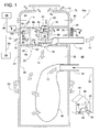
- Figure 1 is a cross-sectional side view of a vacuum canister and a schematic illustration of the remainder of a central vacuum system, wherein the canister includes a filter for capturing carbon dust from a current of air that cools the motor and its electrical drive components.
- Figure 2 is a cross-sectional top view taken generally along line 2-2 of Figure 1, wherein portions of a canister divider system are cutaway to show underlying detail. Also, vent holes are shown elevated from their true position to more clearly show their function.
- Figure 3 is a cross-sectional top view similar to Figure 2 but showing a different embodiment where the carbon dust filter is omitted.
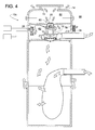
- Figure 4 is a cross-sectional side view similar to Figure 1 but showing one of the dividers omitted.
- Figure 5 is a cross-sectional side view similar to Figure 4 but showing a vacuum system that includes a different type of main filter.
- Figure 6 is a cross-sectional side view similar to Figure 4 but showing a vacuum system that includes a separator in the form of a vortex-generating cylinder and a funnel.
- Figures 1 and 2 show a
vacuum system primary air 12 for cleaning (larger arrows) and conveyssecondary air 14 for cooling (smaller arrows). Amotor 16 drives both amain impeller 18 for movingprimary air 12 and a fan orsecondary impeller 20 for moving coolingair 14. Adivider system 22 installed within a cylindrical or otherwisetubular canister 24 divides the canister into various chambers and directssecondary air 14 in a flow pattern suitable for coolingmotor 16 and for cooling at least one motor drive component 26 (e.g., triac). The flow pattern is such thatair 14 provides ample cooling even though the airflow is partially restricted by asecondary filter 28 that captures carbon dust emitted from the motor's commutator brushes 30. - In operation,
main impeller 18 drawsair 12 from within asuction chamber 32 ofcanister 24, which is installed at a generally fixed location. Asuction inlet 34 connectssuction chamber 32 to a network oftubing 36 that leads to several wall-mountedinlet ports 38 that are installed at various locations throughout a house orbuilding 40. Aflexible hose 42 connects aportable vacuum tool 44 to any of theinlet ports 38 so thattool 44 can be used for vacuuming afloor 46 or other surfaces. - To clean a surface, motor-driven
impeller 18 draws dust-laden air or some other fluid fromambient atmosphere 86 in series throughtool 44, throughhose 42, throughtubing network 36, throughsuction inlet 34, and intosuction chamber 32 where much of the dust and other contaminants collects within a filter bag or accumulates at the bottom ofcanister 24. Amain separator 48 installed betweensuction inlet 34 andmain impeller 18 helps trap the contaminants withincanister 24. Althoughseparator 48 is shown as a dust-collecting filter bag, other separator designs are well within the scope of the invention. Ajoint connector 50 enablescanister 24 to be manually opened to change orclean separator 48 or to empty the canister periodically. In this example, the dust and air are separated by filtration and the dust is collected within a filter bag; however, other methods of separation and collection can be used. - After separating the dust from the air,
main impeller 18 discharges cleaner air through adischarge outlet 52 that exhausts the air toambient atmosphere 86. The term, "ambient atmosphere" refers to any gas or other fluid outsidecanister 24. Examples of ambient atmosphere include, but are not limited to, the air surrounding the canister's exterior, the air just upstream ofsuction inlet 34, and the air withinbuilding 40. - In some embodiments, in order to cool
motor 16 and one or more of itsdrive components 26,divider system 22 comprises afirst divider 54, asecond divider 56 and athird divider 58. First andsecond dividers canister 24 to help define aplenum 60 at the upper end ofcanister 24,suction chamber 32 at the bottom, and a heat-generatingchamber 62 betweenchambers Third divider 58 extends betweendividers chamber 62 into anelectrical chamber 64 and amotor chamber 66.Motor 16 extends intomotor chamber 66, and one or moremotor drive components 26 are disposed withinelectrical chamber 64. - The term, "motor drive component" refers to any heat-generating electrical device that affects the motor's electrical power. Examples of a motor drive component include, but are not limited to, a triac, diac, power transistor, resistor, inverter, etc. Many such motor drive components are particularly suited for central vacuum systems where a variable speed motor drive is important for switching between heavy and light duty vacuuming (e.g., vacuuming floors vs. curtains).
- To provide a path for cooling
air 14 to circulate throughelectrical chamber 64,motor chamber 66 andplenum 60, atubular sidewall 68 ofcanister 24 defines one or moreelectrical chamber inlets 70, anupper end cap 72 defines aplenum inlet 74, andsecond divider 56 defines an opening orelectrical chamber outlet 76.Tubular sidewall 68 also defines one or moremotor chamber outlets 78 that lead tosecondary filter 28. In cases wherethird divider 58 is omitted,motor chamber outlet 78 can be referred to as a heat-generating chamber outlet because the heat-generating chamber would no longer be divided into two distinct chambers (i.e., no longer a motor chamber and an electrical chamber). - To
cool motor 16 andcomponent 26, and to inhibit carbon dust from being discharged to atmosphere,secondary impeller 20 drawsair 14 fromplenum 60, through asecondary impeller inlet 80, and intomotor chamber 66.Impeller 20forces air 14 acrossmotor 16 where some ofair 14 passes between the motor'sstator 82 androtor 84 and other portions ofair 14 pass out over the top ofstator 82 near the motor's commutator brushes 30. After coolingmotor 16,air 14 travels frommotor chamber 66, throughmotor chamber outlet 78, throughsecondary filter 28, and out toambient atmosphere 86.Secondary filter 28 helps capture airborne carbon dust to ensure thatair 14 being exhausted to atmosphere is sufficiently clean. - To supply
plenum 60 with air,impeller 20 creates a negative pressure (below atmospheric pressure) withinplenum 60, which draws ambient air intoplenum 60 throughplenum inlet 74.Electrical chamber outlet 76 allows the negative pressure inplenum 60 to also draw in 14 air that has been preheated bycomponent 26 inelectrical chamber 64. Thus,plenum 60 receives a mixture of ambient air and preheated air, whereinsecondary impeller inlet 80 delivers the mixture tomotor chamber 66. - To cool
motor drive component 26, theair entering plenum 60 throughelectrical chamber outlet 76 reduces the pressure withinelectrical chamber 64 such that ambient air is drawn intochamber 64 viaelectrical chamber inlet 70. Thus,air 14 travels in series throughelectrical chamber inlet 70, throughelectrical chamber 64 to coolcomponent 26, and out throughelectrical chamber outlet 76 to mix with ambient air inplenum 60. Abracket 88 attached tosidewall 68 supportsmotor drive component 26 at a position whereair 14 entering throughelectrical chamber inlet 70 can pass directly across and aroundcomponent 26. - The flow of
air 14 through the upper portion ofcanister 24 is such that the motor chamber pressure is greater than the ambient atmosphere pressure, the ambient atmosphere pressure is greater than the electrical chamber pressure, the electrical chamber pressure is greater than the plenum pressure, and the plenum pressure is greater than the suction pressure insuction chamber 32. The term, "pressure" pertains to absolute pressure rather than gage pressure, thus even air below atmospheric pressure (e.g., below 14.7 psi) can be considered to have a positive absolute pressure. - The
electrical chamber inlet 70 enablescomponent 26 to be cooled by relatively cool ambient air that is generally not preheated bymotor 16. Also, the influx of ambient air throughplenum inlet 74 allowsmotor 16 to receive at least some fresh air that has not first passed acrosscomponent 26. Moreover,component 26 being upstream ofmotor 16 helps prevent the motor brush's carbon dust from contaminatingcomponent 26 or its associated circuit board. - Since
electrical chamber 64 receives unheated ambient air throughelectrical chamber inlet 70, andmotor 16 receives a slightly warmer mixture of air, it may be desirable to have the flow rate ofair 14 passing throughmotor chamber 66 be slightly greater than that passing throughelectrical chamber 64, which in fact is the case with vacuum system 10. - By locating
electrical chamber 64 along the side ofcanister 24,upper end cap 72 can be removed via a joint 90 without disturbing any electrical connections that feed intocanister 24. Examples of such electrical connections include, but are not limited to, apower cord 92 from a power supply 94 (e.g., wall outlet), control-wiring 96 from acontrol panel 98, afuse 100, etc. In a currently preferred embodiment, the electrical connections are supported by thesame bracket 88 that supportsmotor drive component 26. - In another embodiment, shown in Figure 3, a vacuum system 10b is the same as
vacuum system 10a; however,secondary filter 28 is omitted. Withoutfilter 28,motor chamber outlet 78 exhaustsunfiltered air 14 directly to atmosphere. Although carbon dust may be released, removingfilter 28 may increase the cooling ofmotor 16 andcomponent 26. - In another embodiment, shown in Figure 4, a
vacuum system 10c is similar tovacuum system 10a; however,third divider 58,electrical chamber inlet 70 andelectrical chamber outlet 76 are omitted. Withoutthird divider 58,motor 16 and drivecomponent 26 share the same space within heat-generatingchamber 62. In this case,secondary impeller 20forces cooling air 14 to travel in series fromambient atmosphere 86, throughplenum inlet 74, throughplenum 60, throughsecondary impeller inlet 80, into heat-generatingchamber 62 to coolmotor 16 andcomponent 26, through heat-generatingchamber outlet 78, throughsecondary filter 28 to impede carbon dust, and back out toambient atmosphere 86. - In another embodiment, shown in Figure 5, a
vacuum system 10d is the same asvacuum system 10c; however, main separator 48 (in the form of a bag) is replaced by anothermain filter 102 of a different shape. Withfilter 102, dust collects at the bottom of the vacuum canister. - In another embodiment, shown in Figure 6, a
vacuum system 10e is similar tosystems vacuum system 10e separates contaminants fromair 12 using a separator in the form of a vortex-generatingcylinder 104 installed within acylindrical canister 106. A suction inlet 34' leading tangentially intocanister 106 directsair 12 into a downward circular motion aroundcylinder 104. Centrifugal force separates the contaminants fromair 12 by slinging the heavier contaminating particles and against the interior wall ofcanister 106. Afunnel 108 then directs the separated contaminants to the bottom ofcanister 106 for later disposal. Once the contaminants are separated from the air, the cleaner air travels up through a central portion ofcylinder 104. From there,impeller 18 forces the now cleaner air out throughdischarge outlet 52. - Although the invention is described with reference to a preferred embodiment, it should be appreciated by those of ordinary skill in the art that various modifications are well within the scope of the invention. The separators of Figure 5 and 6, for example, can also be used in the vacuum systems illustrated in Figure 1. Therefore, the scope of the invention is to be determined by reference to the following claims.
Claims (20)
- A central vacuum system (10) for reducing the pressure of air to less than that of an ambient atmosphere (86) that contains contaminants, the system (10) comprising:a canister (24) for installation at a substantially fixed location;a divider system (22) disposed within the canister (24) to help define within the canister (24) a suction chamber (32), a motor chamber (66), a plenum (60), and an electrical chamber (64);a motor (16) extending into the motor chamber (66), wherein the motor (16) heats the air therein;a main impeller (18) coupled to the motor (16) to help create a suction pressure within the suction chamber (32);a secondary impeller (20) coupled to the motor (16), wherein the secondary impeller (20) forces air from the ambient atmosphere (86) into the electrical chamber (64), forces air from the electrical chamber (64) into the plenum (60), forces air from the plenum (60) into the motor chamber (66), and forces air from the motor chamber (66) to the ambient atmosphere (86); anda motor drive component (26) disposed within the electrical chamber (64) and being electrically coupled to the motor (16), wherein the air forced through the electrical chamber (64) helps cool the motor drive component (26).
- The central vacuum system (10) of claim 1, wherein the air in the electrical chamber (64) is upstream of the air in the motor chamber (66).
- The central vacuum system (10) of claim 1, wherein the motor chamber (66) conveys air at a greater flow rate than that of the electrical chamber (64).
- The central vacuum system (10) of claim 1, wherein the air in the plenum (60) is cooler than the air in the electrical chamber (64).
- The central vacuum system (10) of claim 1, wherein the electrical chamber (64) conveys air at an electrical chamber pressure, the plenum (60) conveys air at a plenum pressure, the motor chamber (66) conveys air at a motor chamber pressure, and the suction chamber (32) conveys air at a suction pressure, wherein:i. the motor chamber pressure is greater than the ambient atmosphere pressure,ii. the ambient atmosphere pressure is greater than the electrical chamber pressure,iii. the electrical chamber pressure is greater than the plenum pressure, andiv. the plenum pressure is greater than the suction pressure.
- The central vacuum system (10) of claim 1, wherein the plenum (60) is above the electrical chamber (64) and the motor chamber (66), and the suction chamber (32) is below the electrical chamber (64) and the motor chamber (66).
- The central vacuum system (10) of claim 1, wherein the canister (24) comprises a substantially cylindrical outer wall within which the electrical chamber (64) is contained.
- The central vacuum system (10) of claim 7, wherein the weight of the motor drive component (26) is carried by the substantially cylindrical outer wall.
- The central vacuum system (10) of claim 1, wherein the divider system (22) includes a first divider (54) and a second divider (56), wherein the first divider (54) separates the motor chamber (66) from the suction chamber (32), and the second divider (56) separates the plenum (60) from the motor chamber (66), and the second divider (56) defines an opening (76) that places the plenum (60) in fluid communication with the electrical chamber (64).
- The central vacuum system (10) of claim 9, wherein the divider system (22) includes a third divider (58) extending between the first divider (54) and the second divider (56).
- The central vacuum system (10) of claim 1, further comprising:a main separator (48) interposed between the main impeller (18) and the suction chamber (32) to help separate the contaminants from the air that the main impeller (18) draws from the suction chamber (32); anda secondary filter (28) interposed between the motor chamber (66) and the ambient atmosphere (86), wherein the secondary filter (28) helps filter the air passing from the motor chamber (66) to the ambient atmosphere (86).
- A central vacuum system (10) for reducing the pressure of air to less than that of an ambient atmosphere (86) that contains contaminants, the system (10) comprising:a canister (24) that includes a tubular sidewall (68) and an upper end cap (72), wherein the upper end cap (72) defines a plenum inlet (74), and the tubular sidewall (68) defines a suction inlet (34), an electrical chamber inlet (70) and a motor chamber outlet (78);a first divider (54) disposed within the canister (24), wherein the first divider (54) and the tubular sidewall (68) help define a suction chamber (32) that is in fluid communication with the ambient atmosphere (86) via the suction inlet (34);a second divider (56) disposed within the canister (24) and defining an electrical chamber outlet (76), wherein the second divider (56), the tubular sidewall (68) and the upper end cap (72) help define a plenum (60) that is in fluid communication with the ambient atmosphere (86) via the plenum inlet (74);a third divider (58) disposed within the canister (24) and extending between the first divider (54) and the second divider (56), wherein first divider (54), the second divider (56), the third divider (58) and the sidewall (68) help define a motor chamber (66) and an electrical chamber (64), wherein the motor chamber (66) is in fluid communication with the ambient atmosphere (86) via the motor chamber outlet (78), the motor chamber (66) is in fluid communication with the plenum (60), and the electrical chamber (64) is in fluid communication with the ambient atmosphere (86) via the electrical chamber inlet (70);a motor (16) extending into the motor chamber (66), wherein the motor (16) heats the air therein;a main impeller (18) coupled to the motor (16) to help create a suction pressure within the suction chamber (32);a motor drive component (26) disposed within the electrical chamber (64) and being electrically coupled to the motor (16), wherein the motor drive component (26) heats the air within the electrical chamber (64); anda secondary impeller (20) coupled to the motor (16), wherein the secondary impeller (20):i. forces air from the ambient atmosphere (86) into the electrical chamber (64) via the electrical chamber inlet (70),ii. forces air from the electrical chamber (64) into the plenum (60) via the electrical chamber outlet (76),iii. forces air from the ambient atmosphere (86) into the plenum (60) via the plenum inlet (74),iv. forces air from the plenum (60) into the motor chamber (66), andv. forces air from the motor chamber (66) to the ambient atmosphere (86) via the motor chamber outlet (78).
- The central vacuum system (10) of claim 12, wherein the motor chamber (66) conveys air at a greater flow rate than that of the electrical chamber (64).
- The central vacuum system (10) of claim 12, wherein the air in the plenum (60) is cooler than the air in the electrical chamber (64).
- The central vacuum system (10) of claim 12, wherein the electrical chamber (64) conveys air at an electrical chamber pressure, the plenum (60) conveys air at a plenum pressure, the motor chamber (66) conveys air at a motor chamber pressure, and the suction chamber (32) conveys air at a suction pressure, wherein:i. the motor chamber pressure is greater than the ambient atmosphere pressure,ii. the ambient atmosphere pressure is greater than the electrical chamber pressure,iii. the electrical chamber pressure is greater than the plenum pressure, andiv. the plenum pressure is greater than the suction pressure.
- The central vacuum system of claim 12, wherein the plenum (60) is above the electrical chamber (64) and the motor chamber (66), and the suction chamber (32) is below the electrical chamber (64) and the motor chamber (66).
- The central vacuum system (10) of claim 12, further comprising:a main separator (48) interposed between the main impeller (18) and the suction chamber (32) to help separate the contaminants from the air that the main impeller (18) draws from the suction chamber (32); anda secondary filter (28) interposed between the motor chamber (66) and the ambient atmosphere (86), wherein the secondary filter (28) helps filter the air passing from the motor chamber (66) to the ambient atmosphere (86).
- A central vacuum system (10) for reducing the pressure of air to less than that of an ambient atmosphere (86) that contains contaminants, the system (10) comprising:a canister (24) that includes a tubular sidewall (68) and an upper end cap (72), wherein the upper end cap (72) defines a plenum inlet (74), and the tubular sidewall (68) defines a suction inlet (34) and a heat-generating chamber outlet (78);a first divider (54) disposed within the canister (24) and a second divider (56) disposed within the canister (24), such that:i. the second divider (56), the tubular sidewall (68) and the upper end cap (72) help define a plenum (60) that is in fluid communication with the ambient atmosphere (86) via the plenum inlet (74),ii. the first divider (54) and the tubular sidewall (68) help define a suction chamber (32) that is in fluid communication with the suction inlet (34), andiii. the first divider (54), the second divider (56) and the sidewall (68) help define a heat-generating chamber (62) that is in fluid communication with the plenum (60) and the heat-generating chamber outlet (78);a motor (16) extending into the heat-generating chamber (62), wherein the motor (16) heats the air therein;a main impeller (18) coupled to the motor (16) to help create a suction pressure within the suction chamber (32);a main separator (48) interposed between the main impeller (18) and the suction chamber (32) to help separate the contaminants from the air that the main impeller (18) draws from the suction chamber (32);a motor drive component (26) disposed within the heat-generating chamber (62) and being electrically coupled to the motor (16), wherein the motor drive component (26) heats the air within the heat-generating chamber (62); anda secondary impeller (20) coupled to the motor (16), wherein the secondary impeller (20) forces air from the plenum (60) into the heat-generating chamber (62), and the secondary impeller (20) forces air from within the heat-generating chamber (62) out through the heat-generating chamber outlet (78), wherein the air being forced through the heat-generating chamber (62) by the secondary impeller (20) helps cool the motor (16) and helps cool the motor drive component (26); anda secondary filter (28) in series flow relationship with the heat-generating chamber outlet (78), such that the air passing through the heat-generating chamber outlet (78) also passes through the secondary filter (28).
- The central vacuum system (10) of claim 18, wherein the air in the plenum (60) is cooler than the air in the heat-generating chamber (62).
- The central vacuum system (10) of claim 18, wherein the plenum (60) is above the heat-generating chamber (62), and the heat-generating chamber (62) is above the suction chamber (32).
Applications Claiming Priority (1)
| Application Number | Priority Date | Filing Date | Title |
|---|---|---|---|
| US11/039,202 US7406744B2 (en) | 2005-01-20 | 2005-01-20 | Central vacuum system with secondary airflow path |
Publications (2)
| Publication Number | Publication Date |
|---|---|
| EP1683459A2 true EP1683459A2 (en) | 2006-07-26 |
| EP1683459A3 EP1683459A3 (en) | 2009-04-29 |
Family
ID=36168409
Family Applications (1)
| Application Number | Title | Priority Date | Filing Date |
|---|---|---|---|
| EP05356135A Withdrawn EP1683459A3 (en) | 2005-01-20 | 2005-08-11 | Central vacuum system with secondary ariflow path |
Country Status (3)
| Country | Link |
|---|---|
| US (1) | US7406744B2 (en) |
| EP (1) | EP1683459A3 (en) |
| CA (1) | CA2513062C (en) |
Cited By (3)
| Publication number | Priority date | Publication date | Assignee | Title |
|---|---|---|---|---|
| EP2354558A3 (en) * | 2010-01-27 | 2014-10-08 | Behr GmbH & Co. KG | Air conditioning device |
| EP2811235A1 (en) * | 2013-06-03 | 2014-12-10 | AERIAL GmbH | Ventilation device |
| EP3398498A1 (en) * | 2017-05-02 | 2018-11-07 | TROTEC GmbH & Co. KG | Device for insulating layer drying |
Families Citing this family (22)
| Publication number | Priority date | Publication date | Assignee | Title |
|---|---|---|---|---|
| US7716781B2 (en) * | 2002-03-12 | 2010-05-18 | Cube Investments Limited | Suction motor for vacuum cleaner |
| US7260868B2 (en) * | 2004-05-10 | 2007-08-28 | San Ford Machinery Co., Ltd. | Simple dust collector |
| US6856113B1 (en) | 2004-05-12 | 2005-02-15 | Cube Investments Limited | Central vacuum cleaning system motor control circuit mounting post, mounting configuration, and mounting methods |
| WO2006029535A1 (en) | 2004-09-17 | 2006-03-23 | Cube Investments Limited | Cleaner handle and cleaner handle housing sections |
| US7958594B2 (en) | 2005-10-07 | 2011-06-14 | Cube Investments Limited | Central vacuum cleaner cross-controls |
| US7900315B2 (en) * | 2005-10-07 | 2011-03-08 | Cube Investments Limited | Integrated central vacuum cleaner suction device and control |
| CA2562810C (en) | 2005-10-07 | 2015-12-08 | Cube Investments Limited | Central vacuum cleaner multiple vacuum source control |
| US7690075B2 (en) | 2005-10-07 | 2010-04-06 | Cube Investments Limited | Central vacuum cleaner control, unit and system with contaminant sensor |
| ES2664595T3 (en) * | 2008-10-06 | 2018-04-20 | Shop Vac Corporation | Vehicle with a vacuum system |
| US8136618B2 (en) * | 2009-01-21 | 2012-03-20 | The Raymond Corporation | Cyclonic motor cooling for material handling vehicles |
| CN102192166B (en) * | 2010-03-12 | 2016-03-30 | 德昌电机(深圳)有限公司 | Blower fan |
| US8875342B2 (en) * | 2010-03-12 | 2014-11-04 | G.B.D. Corp. | Bleed air valve of a surface cleaning apparatus |
| SE1050719A1 (en) | 2010-06-30 | 2011-11-15 | Corroventa Avfuktning Ab | Fan device and method for cooling and soundproofing a fan |
| US8533906B2 (en) | 2011-07-07 | 2013-09-17 | Shop Vac Corporation | Vacuum cleaner with recirculated cooling air |
| US9457508B2 (en) * | 2013-05-24 | 2016-10-04 | EVO Development, LLC | Thermoforming trim removal systems and methods |
| US10178997B2 (en) | 2014-09-24 | 2019-01-15 | Gyrus Acmi, Inc. | High-speed powered hand tool with improved motor cooling |
| US20170273525A1 (en) * | 2016-03-28 | 2017-09-28 | Nelson Hulli | Convertible Central Vacuum Unit |
| US11560904B2 (en) * | 2018-09-25 | 2023-01-24 | Abb Schweiz Ag | Modular low-noise motor |
| WO2021131494A1 (en) * | 2019-12-26 | 2021-07-01 | 工機ホールディングス株式会社 | Dust collector |
| JP7519926B2 (en) * | 2021-01-22 | 2024-07-22 | 株式会社マキタ | Dust collector |
| JP7526109B2 (en) | 2021-01-22 | 2024-07-31 | 株式会社マキタ | Dust collector |
| US20230135280A1 (en) * | 2021-10-29 | 2023-05-04 | Techtronic Cordless Gp | Shroud for hand vacuum cleaner |
Citations (2)
| Publication number | Priority date | Publication date | Assignee | Title |
|---|---|---|---|---|
| US5412837A (en) | 1992-02-28 | 1995-05-09 | Firma Fedag | Vacuum cleaner |
| US5685894A (en) | 1995-09-13 | 1997-11-11 | Electrolux Corporation | Filter and accessory mount for upright vacuum cleaner exhaust port |
Family Cites Families (17)
| Publication number | Priority date | Publication date | Assignee | Title |
|---|---|---|---|---|
| US3173164A (en) | 1960-05-18 | 1965-03-16 | Whirlpool Co | Builtin vacuum cleaner |
| DK140453C (en) * | 1974-12-21 | 1980-01-28 | Vorwerk Co Interholding | VACUUM CLEANER |
| US4120616A (en) * | 1975-10-06 | 1978-10-17 | Breuer Electric Manufacturing Company | Vacuum cleaner-blower assembly with sound absorbing arrangement |
| US4330899A (en) * | 1980-04-18 | 1982-05-25 | Shop-Vac Corporation | Noise reducing blower motor housing means for vacuum cleaner, or the like |
| DE3107879A1 (en) | 1981-03-02 | 1982-09-16 | Vorwerk & Co Interholding Gmbh, 5600 Wuppertal | FILTER FOR THE COOLING AIR FLOW OF ELECTRICOMMUTATOR MOTORS FOR HOUSEHOLD APPLIANCES |
| DE3225258C2 (en) * | 1982-07-06 | 1985-11-28 | Guido Oberdorfer Wap-Maschinen, 7919 Bellenberg | Vacuum cleaner |
| DE4206188C2 (en) * | 1992-02-28 | 1994-10-13 | Fedag Romanshorn Fa | Suction cleaning device |
| US5353469A (en) * | 1992-07-01 | 1994-10-11 | National Super Service Company | Wet/dry vacuum cleaner with noise reducing housing structure |
| US5400463A (en) * | 1993-02-16 | 1995-03-28 | Beam Of Canada, Inc. | Noise dampened canister vacuum cleaner |
| US5685899A (en) * | 1995-07-28 | 1997-11-11 | Thiele Kaolin Company | Process for conditioning kaolin clays prior to removing impurities |
| US5737797A (en) | 1995-11-28 | 1998-04-14 | Iowa State University Research Foundation, Inc. | Central vacuum with acoustical damping |
| US5813085A (en) * | 1997-02-25 | 1998-09-29 | White Consolidated Industries, Inc. | Motor isolation gasket for central vacuum |
| US6003200A (en) * | 1997-11-14 | 1999-12-21 | Overhead Door Corporation | Powerhead housing assembly for vacuum cleaner |
| GB9726676D0 (en) | 1997-12-17 | 1998-02-18 | Notetry Ltd | A vacuum cleaner |
| US6481050B1 (en) | 2000-07-19 | 2002-11-19 | The Hoover Company | Motor-fan cooling air directed into filter bag |
| CA2332195A1 (en) | 2001-01-24 | 2002-07-24 | Alexandre Plomteux | Quiet central vacuum power unit |
| FI114382B (en) | 2001-02-13 | 2004-10-15 | Fortum Oyj | Central vacuum cleaner dust extraction method and arrangement |
-
2005
- 2005-01-20 US US11/039,202 patent/US7406744B2/en active Active
- 2005-07-22 CA CA2513062A patent/CA2513062C/en active Active
- 2005-08-11 EP EP05356135A patent/EP1683459A3/en not_active Withdrawn
Patent Citations (2)
| Publication number | Priority date | Publication date | Assignee | Title |
|---|---|---|---|---|
| US5412837A (en) | 1992-02-28 | 1995-05-09 | Firma Fedag | Vacuum cleaner |
| US5685894A (en) | 1995-09-13 | 1997-11-11 | Electrolux Corporation | Filter and accessory mount for upright vacuum cleaner exhaust port |
Cited By (3)
| Publication number | Priority date | Publication date | Assignee | Title |
|---|---|---|---|---|
| EP2354558A3 (en) * | 2010-01-27 | 2014-10-08 | Behr GmbH & Co. KG | Air conditioning device |
| EP2811235A1 (en) * | 2013-06-03 | 2014-12-10 | AERIAL GmbH | Ventilation device |
| EP3398498A1 (en) * | 2017-05-02 | 2018-11-07 | TROTEC GmbH & Co. KG | Device for insulating layer drying |
Also Published As
| Publication number | Publication date |
|---|---|
| CA2513062A1 (en) | 2006-07-20 |
| US20060156504A1 (en) | 2006-07-20 |
| CA2513062C (en) | 2011-01-11 |
| US7406744B2 (en) | 2008-08-05 |
| EP1683459A3 (en) | 2009-04-29 |
Similar Documents
| Publication | Publication Date | Title |
|---|---|---|
| CA2513062C (en) | Central vacuum system with secondary airflow path | |
| KR100549990B1 (en) | Dust collecting apparatus for vacuum cleaner | |
| US20020046438A1 (en) | Upright-type vacuum cleaner | |
| WO2020138929A1 (en) | Dust container and cleaner including | |
| CN101032384A (en) | Portable vacuum cleaner | |
| KR20140009338A (en) | Vacuum cleaner | |
| JP2022522053A (en) | Wet and dry vacuum cleaner | |
| KR101390549B1 (en) | Vacuum cleaner | |
| US20210186286A1 (en) | Vacuum cleaner | |
| US7080425B2 (en) | Vacuum canister and mounting bracket for use therewith | |
| CN107105955B (en) | Electric vacuum cleaner | |
| US20090056289A1 (en) | Air purifier | |
| US6162287A (en) | Filter for vacuum cleaner | |
| JP2003310502A (en) | Vacuum cleaner | |
| CN2927961Y (en) | Portable vacuum cleaner | |
| CN101242770A (en) | Filter mounting structure of vacuum cleaner | |
| EP1542573B1 (en) | Central vacuum cleaner and its central unit | |
| KR200466747Y1 (en) | Vacuum cleaner | |
| JPH1080381A (en) | Cleaner | |
| KR101433253B1 (en) | Oil mist collecting device | |
| CN109717793B (en) | Electric vacuum cleaner | |
| KR101459629B1 (en) | Air conditioner | |
| CN113071542B (en) | Working cart with built-in dust collection system | |
| CN109717791B (en) | Electric dust collector | |
| JP4299481B2 (en) | Dust collection mechanism and dust collection method for electronic component manufacturing apparatus |
Legal Events
| Date | Code | Title | Description |
|---|---|---|---|
| PUAI | Public reference made under article 153(3) epc to a published international application that has entered the european phase |
Free format text: ORIGINAL CODE: 0009012 |
|
| AK | Designated contracting states |
Kind code of ref document: A2 Designated state(s): AT BE BG CH CY CZ DE DK EE ES FI FR GB GR HU IE IS IT LI LT LU LV MC NL PL PT RO SE SI SK TR |
|
| AX | Request for extension of the european patent |
Extension state: AL BA HR MK YU |
|
| PUAL | Search report despatched |
Free format text: ORIGINAL CODE: 0009013 |
|
| AK | Designated contracting states |
Kind code of ref document: A3 Designated state(s): AT BE BG CH CY CZ DE DK EE ES FI FR GB GR HU IE IS IT LI LT LU LV MC NL PL PT RO SE SI SK TR |
|
| AX | Request for extension of the european patent |
Extension state: AL BA HR MK YU |
|
| AKX | Designation fees paid | ||
| REG | Reference to a national code |
Ref country code: DE Ref legal event code: 8566 |
|
| STAA | Information on the status of an ep patent application or granted ep patent |
Free format text: STATUS: THE APPLICATION IS DEEMED TO BE WITHDRAWN |
|
| 18D | Application deemed to be withdrawn |
Effective date: 20091030 |