EP1681530A1 - Spacer element for panel radiator and method of making the same - Google Patents
Spacer element for panel radiator and method of making the same Download PDFInfo
- Publication number
- EP1681530A1 EP1681530A1 EP06100321A EP06100321A EP1681530A1 EP 1681530 A1 EP1681530 A1 EP 1681530A1 EP 06100321 A EP06100321 A EP 06100321A EP 06100321 A EP06100321 A EP 06100321A EP 1681530 A1 EP1681530 A1 EP 1681530A1
- Authority
- EP
- European Patent Office
- Prior art keywords
- spacer element
- axial hole
- metal piece
- aperture
- hollows
- Prior art date
- Legal status (The legal status is an assumption and is not a legal conclusion. Google has not performed a legal analysis and makes no representation as to the accuracy of the status listed.)
- Granted
Links
- 125000006850 spacer group Chemical group 0.000 title claims abstract description 46
- 238000004519 manufacturing process Methods 0.000 title description 3
- 239000002184 metal Substances 0.000 claims abstract description 54
- 229910052751 metal Inorganic materials 0.000 claims abstract description 54
- 239000012530 fluid Substances 0.000 claims abstract description 14
- 239000000463 material Substances 0.000 claims abstract description 6
- 238000000034 method Methods 0.000 claims description 20
- 238000005245 sintering Methods 0.000 claims description 7
- 238000003466 welding Methods 0.000 claims description 6
- 238000009826 distribution Methods 0.000 description 3
- 238000010438 heat treatment Methods 0.000 description 3
- XLYOFNOQVPJJNP-UHFFFAOYSA-N water Substances O XLYOFNOQVPJJNP-UHFFFAOYSA-N 0.000 description 3
- XEEYBQQBJWHFJM-UHFFFAOYSA-N Iron Chemical compound [Fe] XEEYBQQBJWHFJM-UHFFFAOYSA-N 0.000 description 2
- 239000002923 metal particle Substances 0.000 description 2
- 230000002093 peripheral effect Effects 0.000 description 2
- 238000007792 addition Methods 0.000 description 1
- 230000006835 compression Effects 0.000 description 1
- 238000007906 compression Methods 0.000 description 1
- 238000010276 construction Methods 0.000 description 1
- 230000001419 dependent effect Effects 0.000 description 1
- 229910052742 iron Inorganic materials 0.000 description 1
- 238000012986 modification Methods 0.000 description 1
- 230000004048 modification Effects 0.000 description 1
- 238000000465 moulding Methods 0.000 description 1
- 239000011236 particulate material Substances 0.000 description 1
Images


Classifications
-
- B—PERFORMING OPERATIONS; TRANSPORTING
- B22—CASTING; POWDER METALLURGY
- B22F—WORKING METALLIC POWDER; MANUFACTURE OF ARTICLES FROM METALLIC POWDER; MAKING METALLIC POWDER; APPARATUS OR DEVICES SPECIALLY ADAPTED FOR METALLIC POWDER
- B22F5/00—Manufacture of workpieces or articles from metallic powder characterised by the special shape of the product
- B22F5/10—Manufacture of workpieces or articles from metallic powder characterised by the special shape of the product of articles with cavities or holes, not otherwise provided for in the preceding subgroups
- B22F5/106—Tube or ring forms
-
- B—PERFORMING OPERATIONS; TRANSPORTING
- B22—CASTING; POWDER METALLURGY
- B22F—WORKING METALLIC POWDER; MANUFACTURE OF ARTICLES FROM METALLIC POWDER; MAKING METALLIC POWDER; APPARATUS OR DEVICES SPECIALLY ADAPTED FOR METALLIC POWDER
- B22F7/00—Manufacture of composite layers, workpieces, or articles, comprising metallic powder, by sintering the powder, with or without compacting wherein at least one part is obtained by sintering or compression
- B22F7/06—Manufacture of composite layers, workpieces, or articles, comprising metallic powder, by sintering the powder, with or without compacting wherein at least one part is obtained by sintering or compression of composite workpieces or articles from parts, e.g. to form tipped tools
- B22F7/062—Manufacture of composite layers, workpieces, or articles, comprising metallic powder, by sintering the powder, with or without compacting wherein at least one part is obtained by sintering or compression of composite workpieces or articles from parts, e.g. to form tipped tools involving the connection or repairing of preformed parts
-
- B—PERFORMING OPERATIONS; TRANSPORTING
- B63—SHIPS OR OTHER WATERBORNE VESSELS; RELATED EQUIPMENT
- B63H—MARINE PROPULSION OR STEERING
- B63H8/00—Sail or rigging arrangements specially adapted for water sports boards, e.g. for windsurfing or kitesurfing
- B63H8/20—Rigging arrangements involving masts, e.g. for windsurfing
- B63H8/22—Rigging arrangements involving masts, e.g. for windsurfing for connecting wishbones to the mast
-
- F—MECHANICAL ENGINEERING; LIGHTING; HEATING; WEAPONS; BLASTING
- F28—HEAT EXCHANGE IN GENERAL
- F28F—DETAILS OF HEAT-EXCHANGE AND HEAT-TRANSFER APPARATUS, OF GENERAL APPLICATION
- F28F9/00—Casings; Header boxes; Auxiliary supports for elements; Auxiliary members within casings
- F28F9/26—Arrangements for connecting different sections of heat-exchange elements, e.g. of radiators
- F28F9/262—Arrangements for connecting different sections of heat-exchange elements, e.g. of radiators for radiators
-
- F—MECHANICAL ENGINEERING; LIGHTING; HEATING; WEAPONS; BLASTING
- F28—HEAT EXCHANGE IN GENERAL
- F28F—DETAILS OF HEAT-EXCHANGE AND HEAT-TRANSFER APPARATUS, OF GENERAL APPLICATION
- F28F2240/00—Spacing means
Definitions
- the present invention concerns a method to make a spacer element and the spacer element thus made, able to be inserted between the walls of a panel of a heat radiator, so as to prevent said walls being crushed during the steps to connect them under pressure with a relative connection pipe.
- a heat radiator such as for example a hot water heating plant, a heated towel rail or other, comprising one or more panels shaped so as to define inside them a compartment substantially closed by two walls, inside which a heat carrier fluid circulates.
- Such panels are hydraulically connected by interposing, in twos, a connection element which is pressure welded to the relative panels, in order to guarantee the watertight seal of the connection.
- This known spacer element has a cylindrical body, which has an axial hole that during use faces towards the connection element, and a lateral aperture arranged radially with respect to the axial hole and communicating therewith in order to achieve a hydraulic continuity between the connection element and the inner compartment of the panel.
- This known spacer has the disadvantage however that it completely cancels the secondary flow of the heat carrier fluid in the zones opposite said lateral aperture, that is, towards the corners and edges of the panel, concentrating the distribution of the heat carrier fluid only in the central part of the compartment.
- the method to achieve the known spacer provides operations to bend and draw a metal sheet and has the disadvantage that it requires many steps to work and deform the sheet.
- One purpose of the present invention is to perfect a method to achieve a spacer element which is simple and requires a limited number of working steps in order to achieve it.
- Another purpose of the present invention is to achieve a spacer element that, inserted inside a panel of a heat radiator, will allow to obtain a better distribution of the heat carrier fluid in the compartment of the panel, obtaining a greater heat yield with respect to that obtainable with the state of the art.
- the Applicant has devised, tested and embodied the present invention to overcome the shortcomings of the state of the art and to obtain these and other purposes and advantages.
- a method according to the present invention is used to achieve a spacer element able to be inserted between the walls of a panel of a heat radiator in correspondence with a transit aperture.
- the transit aperture is arranged in correspondence with a connection element, for example a connector, through which a heat carrier fluid flows, for example hot water, steam, or other hot fluid, which circulates between the walls of the panel.
- a connection element for example a connector
- a heat carrier fluid flows, for example hot water, steam, or other hot fluid, which circulates between the walls of the panel.
- the method comprises at least the steps as indicated as follows.
- a first metal piece is made by sintering, substantially cylindrical in shape and comprising at least a first axial hole and at least a first part of a lateral aperture which branches off radially from the axial hole.
- a second metal piece is made with a substantially cylindrical shape and the diameter substantially equal to that of the first metal piece.
- the first and the second step can be performed simultaneously, or one after the other irrespective of the order of performance.
- the first and the second metal piece are arranged one on the other and attached together, for example by welding, coaxially so as to define a body.
- the spacer element according to the present invention therefore comprises a body defined in turn by at least two substantially cylindrical metal pieces, attached coaxially one on the other and at least one of which is made of sintered material.
- both the metal pieces are made of sintered material and, according to another variant of the invention, one of the two metal pieces consists of a metal washer.
- the sintering process performed according to the invention provides to use metal particles which are pressed in two molds: a first mold to define the first metal piece, and a second to define the second metal piece.
- the body comprises an axial hole, which affects at least a part of its thickness and can be blind or through, and a lateral aperture which branches off radially from the axial hole and which communicates with the latter.
- the spacer element also comprises, in addition to the lateral aperture, at least two radial holes made in the body, each of which branches off radially from the axial hole and communicates with the latter.
- At least two hollows are made, with a substantially semi-circular shape.
- Each hollow branches off radially from the axial hole and communicates with the latter.
- Each of the radial holes, or hollows, has a cross section of a size less than that of the lateral aperture.
- Two semi-circular zones are defined on the body, separated from each other by a first median transverse plane "Y", so that the lateral aperture is arranged in a first semi-circular zone and the radial holes, or hollows, are arranged in a second semi-circular zone.
- the radial holes, or hollows are arranged on opposite sides with respect to a second median transverse plane "X" passing through the lateral aperture and substantially orthogonal to the first median transverse plane "Y".
- the spacer element according to the invention inserted inside a panel of a heat radiator, allows to obtain a more efficient distribution of the heat carrier fluid both in the central zone of the compartment of the panel, and also in the zones opposite the lateral aperture, that is, towards the corners and edges of the panel.
- the lateral aperture has a substantially polygonal or curvilinear cross section.
- a spacer element 10 is inserted between the walls 32 of a panel 31 of a heat radiator 30 in correspondence with a transit aperture 34.
- a connection 35 through which a heat carrier fluid passes, for example hot water or steam, is connected to said transit aperture 34.
- the spacer element 10 (figs. 3 and 4) comprises a body 11, substantially cylindrical, having an axial hole 13 which passes through the body 11.
- the spacer element 10 is able to be mounted in the panel 31 in such a manner that the axial hole 13 faces the transit aperture 34 so as to define a channel for the heat carrier fluid.
- the body 11 is defined by two metal pieces, respectively first 18 and second 19 (fig. 3).
- the first metal piece 18 comprises a first part 13a of the axial hole 13 and, on its upper surface 23 facing towards the second metal piece 19, has four studs 21 shown in fig. 5.
- the two metal pieces 18 and 19 are attached to each other by means of welding, performed in a known manner, for example projection, during which the studs 21 are melted.
- the second metal piece 19 also comprises a second part 13b of the axial hole 13.
- a lateral aperture 15 (figs. 3 and 4) is made in the first metal piece 18, and also two radial holes 16, which branch off radially from the axial hole 13 and communicate therewith.
- the lateral aperture 15 has a rectangular cross section and has three walls made in the first metal piece 18 and the fourth wall defined by the lower surface 24 of the second metal piece 19 (shown in fig. 5), when the two metal pieces 18, 19 are located one on the other.
- section of the lateral aperture 15 can have another polygonal shape, or also curvilinear.
- zone of the lower surface 24, which during use defines a wall of the lateral aperture 15, can also be non plane.
- the two radial holes 16 are smaller in size than those of the lateral aperture 15 and have a preferably circular cross section.
- the two radial holes 16 are arranged symmetrical with respect to a second median plane "X" transverse to the body 11 and passing through the lateral aperture 15.
- the longitudinal axis of each radial hole 16 forms an angle a of about 45° with said second median plane "X".
- said angle a can be different from 45°, and it is also provided that the two radial holes 16 can be asymmetrical with respect to the second median plane "X".
- the lateral aperture 15 (figs. 3 and 4) is arranged in a first zone of the body 11 and the two radial holes 16, or hollows 17, are arranged in a second zone of the body 11, where the first and the second zone are separated by a first median transverse plane "Y" substantially orthogonal to the second median plane "X".
- the spacer element 10 (figs. 1 and 2), inserted between the walls 32 of the panel 31, is positioned so that the lateral aperture 15 is oriented to direct the main flow of heat carrier fluid towards the central part of the inner compartment of the panel 31.
- the two radial holes 16, or hollows 17, face towards the edges 36 of the panel 31, so as to direct the secondary flow to said zones.
- the efficiency of the heat radiator 30, in which the spacer element 10 according to the present invention is mounted is greater than that of other known solutions.
- the size and position of the two radial holes 16, or the two hollows 17, can advantageously vary according to the construction characteristics of the panel 31.
- the body 11 is made of sintered material by molding metal particles in two molds, wherein a first mold defines the first metal piece 18, achieving the first part 13a of the axial hole 13, the three walls of the aperture 15, the two radial holes 16, or hollows 17, and the studs 21.
- the second mold defines the second metal piece 19 of the body 11, achieving the second part 13b of the axial hole 13.
- the spacer element 10 is made according to a method according to the invention which comprises at least the steps indicated as follows.
- the first metal piece 18 is made by sintering, substantially cylindrical in shape and comprising the first axial hole 13a, the lateral aperture 15 and the studs 21.
- the second metal piece 19 is made by sintering, with the diameter substantially equal to that of the first metal piece 18.
- the second metal piece 19 can also consist of a simple washer made of iron, molded or turned, with a thickness such as to guarantee sufficient resistance to the compression that the spacer element 10 is subjected to during the welding step between the connection 35 and the panels 31.
- the first and the second step can be performed simultaneously, or one after the other irrespective of the order.
- the first and the second metal piece 18, 19 are arranged one on the other and attached together coaxially by welding, so as to define the body 11.
- the method also comprises another step, during which the two radial holes 16, or hollows 17, are made in the body 11. This step can be performed during the first step, or between the first and the third step, or directly on the body 11 after the third step.
- the second axial hole 13b is made on the second metal piece 19; during the third step, said second axial hole 13b is arranged coaxial with the first axial hole 13a.
Landscapes
- Engineering & Computer Science (AREA)
- Mechanical Engineering (AREA)
- Manufacturing & Machinery (AREA)
- Chemical & Material Sciences (AREA)
- General Engineering & Computer Science (AREA)
- Ocean & Marine Engineering (AREA)
- Physics & Mathematics (AREA)
- Thermal Sciences (AREA)
- Combustion & Propulsion (AREA)
- Composite Materials (AREA)
- Materials Engineering (AREA)
- Heat-Exchange Devices With Radiators And Conduit Assemblies (AREA)
- Connection Of Plates (AREA)
- Lining Or Joining Of Plastics Or The Like (AREA)
- Manufacture Of Electron Tubes, Discharge Lamp Vessels, Lead-In Wires, And The Like (AREA)
- Devices For Indicating Variable Information By Combining Individual Elements (AREA)
Abstract
Description
- The present invention concerns a method to make a spacer element and the spacer element thus made, able to be inserted between the walls of a panel of a heat radiator, so as to prevent said walls being crushed during the steps to connect them under pressure with a relative connection pipe.
- A heat radiator is known, such as for example a hot water heating plant, a heated towel rail or other, comprising one or more panels shaped so as to define inside them a compartment substantially closed by two walls, inside which a heat carrier fluid circulates.
- Such panels are hydraulically connected by interposing, in twos, a connection element which is pressure welded to the relative panels, in order to guarantee the watertight seal of the connection.
- To prevent the radiating panels from deforming during the pressure welding steps, it is known to insert inside them a spacer element which contrasts the pressure exerted, and thus prevent the walls of the panel from deforming.
- This known spacer element has a cylindrical body, which has an axial hole that during use faces towards the connection element, and a lateral aperture arranged radially with respect to the axial hole and communicating therewith in order to achieve a hydraulic continuity between the connection element and the inner compartment of the panel.
- It is known to achieve on said body a lateral aperture with a maximum extension equal to the half of the lateral surface of the body, so that by suitably orienting the spacer element in the panel, it is possible to direct and limit the flow of heat carrier fluid towards the central part of the compartment of the panel.
- This known spacer has the disadvantage however that it completely cancels the secondary flow of the heat carrier fluid in the zones opposite said lateral aperture, that is, towards the corners and edges of the panel, concentrating the distribution of the heat carrier fluid only in the central part of the compartment.
- The method to achieve the known spacer provides operations to bend and draw a metal sheet and has the disadvantage that it requires many steps to work and deform the sheet.
- From DE-A-25 06 778 it is known a spacer for a heating radiator constituted by a cylindrical metal piece, having a central hole and peripheral radial apertures, and by a metal washer which is connected to one lateral surface of the cylindrical metal piece to laterally close the peripheral radial apertures. This known spacer is quite complicated to be manufactured and requires a lot of working steps.
- From GB-A-2 271 526 it is known a method to manufacture a spacer for a central heating radiator, by compacting particulate material in a die comprising a plate having a vertical cavity, a top punch and a bottom punch. An inner core rod forms a central passageway in the spacer and side core rods form the side holes. This known manufacturing method has the disadvantage to be too complicated and to require a lot of working steps.
- One purpose of the present invention is to perfect a method to achieve a spacer element which is simple and requires a limited number of working steps in order to achieve it.
- Another purpose of the present invention is to achieve a spacer element that, inserted inside a panel of a heat radiator, will allow to obtain a better distribution of the heat carrier fluid in the compartment of the panel, obtaining a greater heat yield with respect to that obtainable with the state of the art.
- The Applicant has devised, tested and embodied the present invention to overcome the shortcomings of the state of the art and to obtain these and other purposes and advantages.
- The present invention is set forth and characterized in the main claims, while the dependent claims describe other characteristics of the invention or variants to the main inventive idea.
- In accordance with the above purposes, a method according to the present invention is used to achieve a spacer element able to be inserted between the walls of a panel of a heat radiator in correspondence with a transit aperture.
- The transit aperture is arranged in correspondence with a connection element, for example a connector, through which a heat carrier fluid flows, for example hot water, steam, or other hot fluid, which circulates between the walls of the panel.
- According to a characteristic of the present invention, the method comprises at least the steps as indicated as follows.
- In a first step, a first metal piece is made by sintering, substantially cylindrical in shape and comprising at least a first axial hole and at least a first part of a lateral aperture which branches off radially from the axial hole.
- In a second step, a second metal piece is made with a substantially cylindrical shape and the diameter substantially equal to that of the first metal piece.
- The first and the second step can be performed simultaneously, or one after the other irrespective of the order of performance.
- In a third step, the first and the second metal piece are arranged one on the other and attached together, for example by welding, coaxially so as to define a body.
- Thanks to the method according to the present invention, by means of the sintering process it is possible to make a spacer element simply and with a number of working steps which is limited with respect to the state of the art.
- The spacer element according to the present invention therefore comprises a body defined in turn by at least two substantially cylindrical metal pieces, attached coaxially one on the other and at least one of which is made of sintered material.
- According to a variant of the invention, both the metal pieces are made of sintered material and, according to another variant of the invention, one of the two metal pieces consists of a metal washer.
- The sintering process performed according to the invention provides to use metal particles which are pressed in two molds: a first mold to define the first metal piece, and a second to define the second metal piece.
- The body comprises an axial hole, which affects at least a part of its thickness and can be blind or through, and a lateral aperture which branches off radially from the axial hole and which communicates with the latter.
- According to a preferential embodiment of the invention, the spacer element also comprises, in addition to the lateral aperture, at least two radial holes made in the body, each of which branches off radially from the axial hole and communicates with the latter.
- According to a variant of the present invention, on the upper surface of the first metal piece, which during use faces the second metal piece, instead of radial holes, at least two hollows are made, with a substantially semi-circular shape.
- Each hollow branches off radially from the axial hole and communicates with the latter.
- Each of the radial holes, or hollows, has a cross section of a size less than that of the lateral aperture.
- Two semi-circular zones are defined on the body, separated from each other by a first median transverse plane "Y", so that the lateral aperture is arranged in a first semi-circular zone and the radial holes, or hollows, are arranged in a second semi-circular zone.
- Moreover, the radial holes, or hollows, are arranged on opposite sides with respect to a second median transverse plane "X" passing through the lateral aperture and substantially orthogonal to the first median transverse plane "Y".
- Thanks to this characteristic, the spacer element according to the invention, inserted inside a panel of a heat radiator, allows to obtain a more efficient distribution of the heat carrier fluid both in the central zone of the compartment of the panel, and also in the zones opposite the lateral aperture, that is, towards the corners and edges of the panel.
- According to the invention, the lateral aperture has a substantially polygonal or curvilinear cross section.
- These and other characteristics of the present invention will become apparent from the following description of a preferential form of embodiment, given as a non-restrictive example with reference to the attached drawings wherein:
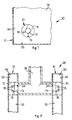
- fig. 1 is a lateral section of a panel of a heat radiator in which a spacer element according to the present invention is inserted;
- fig. 2 is a detail of fig. 1;
- fig. 3 is a lateral view of the spacer element;
- fig. 4 is a plane view of the spacer element;
- fig. 5 is an exploded view of a variant of the spacer element;
- fig. 6 is a section of the variant from VI to VI of fig. 4.
- With reference to figs. 1 and 2, a
spacer element 10 according to the present invention is inserted between thewalls 32 of apanel 31 of aheat radiator 30 in correspondence with atransit aperture 34. - A
connection 35, through which a heat carrier fluid passes, for example hot water or steam, is connected to saidtransit aperture 34. - The spacer element 10 (figs. 3 and 4) comprises a
body 11, substantially cylindrical, having anaxial hole 13 which passes through thebody 11. - The
spacer element 10 is able to be mounted in thepanel 31 in such a manner that theaxial hole 13 faces thetransit aperture 34 so as to define a channel for the heat carrier fluid. - The
body 11 is defined by two metal pieces, respectively first 18 and second 19 (fig. 3). - The
first metal piece 18 comprises afirst part 13a of theaxial hole 13 and, on itsupper surface 23 facing towards thesecond metal piece 19, has fourstuds 21 shown in fig. 5. - The two
metal pieces studs 21 are melted. - The
second metal piece 19 also comprises asecond part 13b of theaxial hole 13. - Alternatively, it is provided to make the
second metal piece 19 without thesecond part 13b of theaxial hole 13, therefore obtaining a blindaxial hole 13. - A lateral aperture 15 (figs. 3 and 4) is made in the
first metal piece 18, and also tworadial holes 16, which branch off radially from theaxial hole 13 and communicate therewith. - The
lateral aperture 15 has a rectangular cross section and has three walls made in thefirst metal piece 18 and the fourth wall defined by the lower surface 24 of the second metal piece 19 (shown in fig. 5), when the twometal pieces - It is provided that the section of the
lateral aperture 15 can have another polygonal shape, or also curvilinear. - It is also provided that the zone of the lower surface 24, which during use defines a wall of the
lateral aperture 15, can also be non plane. - The two
radial holes 16 are smaller in size than those of thelateral aperture 15 and have a preferably circular cross section. - The two
radial holes 16 are arranged symmetrical with respect to a second median plane "X" transverse to thebody 11 and passing through thelateral aperture 15. The longitudinal axis of eachradial hole 16 forms an angle a of about 45° with said second median plane "X". - It is provided that said angle a can be different from 45°, and it is also provided that the two
radial holes 16 can be asymmetrical with respect to the second median plane "X". - According to a variant shown in figs. 5 and 6, on the
upper surface 23 of thefirst metal piece 18, instead of the radial holes 16, shown by dashes in fig. 6, there are twohollows 17, substantially semi-circular in shape. - In another variant solution not shown here, it is provided to make the two
radial holes 16, or hollows 17, in thesecond metal piece 19. - According to one embodiment of the invention, the lateral aperture 15 (figs. 3 and 4) is arranged in a first zone of the
body 11 and the tworadial holes 16, or hollows 17, are arranged in a second zone of thebody 11, where the first and the second zone are separated by a first median transverse plane "Y" substantially orthogonal to the second median plane "X". - The spacer element 10 (figs. 1 and 2), inserted between the
walls 32 of thepanel 31, is positioned so that thelateral aperture 15 is oriented to direct the main flow of heat carrier fluid towards the central part of the inner compartment of thepanel 31. - Consequently, the two
radial holes 16, or hollows 17, face towards theedges 36 of thepanel 31, so as to direct the secondary flow to said zones. - Thanks to the presence of the two
radial holes 16, or hollows 17, the efficiency of theheat radiator 30, in which thespacer element 10 according to the present invention is mounted, is greater than that of other known solutions. - According to the present invention, the size and position of the two
radial holes 16, or the twohollows 17, can advantageously vary according to the construction characteristics of thepanel 31. - The
body 11 is made of sintered material by molding metal particles in two molds, wherein a first mold defines thefirst metal piece 18, achieving thefirst part 13a of theaxial hole 13, the three walls of theaperture 15, the tworadial holes 16, or hollows 17, and thestuds 21. - The second mold defines the
second metal piece 19 of thebody 11, achieving thesecond part 13b of theaxial hole 13. - The
spacer element 10 is made according to a method according to the invention which comprises at least the steps indicated as follows. - In a first step, the
first metal piece 18 is made by sintering, substantially cylindrical in shape and comprising the firstaxial hole 13a, thelateral aperture 15 and thestuds 21. - In a second step, the
second metal piece 19 is made by sintering, with the diameter substantially equal to that of thefirst metal piece 18. - Alternatively, the
second metal piece 19 can also consist of a simple washer made of iron, molded or turned, with a thickness such as to guarantee sufficient resistance to the compression that thespacer element 10 is subjected to during the welding step between theconnection 35 and thepanels 31. - The first and the second step can be performed simultaneously, or one after the other irrespective of the order.
- In a third step, the first and the
second metal piece body 11. - The method also comprises another step, during which the two
radial holes 16, or hollows 17, are made in thebody 11. This step can be performed during the first step, or between the first and the third step, or directly on thebody 11 after the third step. - According to a variant that is not shown here, during the first step only one part of the
aperture 15 is made on thefirst metal piece 18 and, during the second step the second part of theaperture 15 is made on thesecond metal piece 19. - According to one embodiment of the invention, during the second step the second
axial hole 13b is made on thesecond metal piece 19; during the third step, said secondaxial hole 13b is arranged coaxial with the firstaxial hole 13a. - It is clear that modifications and/or additions of parts or steps may be made to the
spacer element 10 and relative method as described heretofore, without departing from the field and scope of the present invention. - It is also clear that, although the present invention has been described with reference to some specific examples, a person of skill in the art shall certainly be able to achieve many other equivalent forms of methods to make spacer elements for a panel of a heat radiator, and spacer elements thus made, having the characteristics as set forth in the claims and hence all coming within the field of protection defined thereby.
Claims (17)
- Spacer element able to be inserted between the walls (32) of a panel (31) of a heat radiator (30) in correspondence with an aperture (34) for the transit of the heat carrier fluid able to circulate between said walls (32), comprising a substantially cylindrical body which is provided both with an axial hole (13), which affects at least a part of its thickness and which, during use, is able to face towards said transit aperture (34), and also with at least a lateral aperture (15) which branches off radially from said axial hole (13) and communicates therewith, characterized in that said body (11) comprises at least two metal pieces (18, 19) of substantially cylindrical shape, coaxially attached one on the other, and of which at least one is made of sintered material, in that said lateral aperture (15) is made in at least one of said metal pieces (18, 19), and in that in addition to said lateral aperture (15) said body (11) also comprises at least two radial holes (16) or hollows (17), each of which branches off radially from said axial hole (13) and communicates therewith.
- Spacer element as in claim 1, characterized in that both metal pieces (18, 19) are made of sintered material.
- Spacer element as in claim 1 or 2, characterized in that one of the two metal pieces (18, 19) consists of a metal washer.
- Spacer element as in claim 1, 2 or 3, characterized in that each of said hollows (17) is made on a surface (23) of one of said metal pieces (18) which during use faces the other metal piece (19).
- Spacer element as in any claim hereinbefore, wherein said body (11) comprises two semi-circular zones divided from each other by a first median transverse plane (Y), characterized in that said lateral aperture (15) is arranged in a first of said zones of said body (11) and that said radial holes (16), or said hollows (17), are arranged in a second of said zones of said body (11).
- Spacer element as in claim 5, characterized in that said radial holes (16) or said hollows (17) are arranged on opposite sides with respect to a second median transverse plane (X) passing through said lateral aperture (15) and substantially orthogonal to said first median transverse plane (Y).
- Spacer element as in any claim hereinbefore, characterized in that each of said radial holes (16), or of said hollows (17), has a cross section of a smaller size than that of said lateral aperture (15).
- Spacer element as in any claim hereinbefore, characterized in that said lateral aperture (15) has a substantially polygonal or curvilinear cross section.
- Spacer element as in any claim hereinbefore, characterized in that said first and said second metal piece (18, 19) are attached to each other by means of welding.
- Spacer element as in any claim hereinbefore, characterized in that said axial hole (13) is blind or through.
- Method to make a spacer element (10) able to be inserted between the walls (32) of a panel (31) of a heat radiator (30) in correspondence with a transit aperture (34) of the heat carrier fluid circulating between said walls (32), characterized in that it comprises at least the following steps.- a first step, during which a first metal piece (18) is made by sintering, substantially cylindrical in shape and comprising at least a first axial hole (13a) and at least a first part of a lateral aperture (15) which branches off radially from said axial hole (13a);- a second step, during which a second metal piece (19) is made, substantially cylindrical in shape and with the diameter substantially equal to that of said first metal piece (18);- a third step, during which said first and said second metal piece (18, 19) are arranged one on the other and attached together coaxially so as to define a body (11).
- Method as in claim 11, characterized in that during said second step, said second metal piece (19) is made by sintering.
- Method as in claim 11 or 12, characterized in that it comprises at least another step, during which at least two radial holes (16) or at least two hollows (17) are made in said body (11), each of which branches off radially from said axial hole (13).
- Method as in claim 13, wherein said body (11) comprises two semi-circular zones divided from each other by a first median transverse plane (Y), characterized in that said lateral aperture (15) is made in a first of said zones of said body (11), and in that said radial holes (16) or said hollows (17) are made in a second of said zones of said body (11).
- Method as in claim 14, characterized in that said radial holes (16) or said hollows (17) are made on opposite sides with respect to a second median transverse plane (X) passing through said lateral aperture (15) and substantially orthogonal to said first median transverse plane (Y).
- Method as in any claim from 11 to 15 inclusive, characterized in that during said second step a second part of said aperture (15) is made on said second metal piece (19).
- Method as in any claim from 11 to 16 inclusive, characterized in that, during said second step, on said second metal piece (19) a second axial hole (13b) is made which, during said third step, is arranged coaxial with said first axial hole (13a).
Priority Applications (1)
| Application Number | Priority Date | Filing Date | Title |
|---|---|---|---|
| PL06100321T PL1681530T3 (en) | 2005-01-18 | 2006-01-13 | Spacer element for panel radiator and method of making the same |
Applications Claiming Priority (1)
| Application Number | Priority Date | Filing Date | Title |
|---|---|---|---|
| IT000002A ITUD20050002A1 (en) | 2005-01-18 | 2005-01-18 | process for making a spacer element for a panel of a thermal radiator, and a spacer element thus made |
Publications (2)
| Publication Number | Publication Date |
|---|---|
| EP1681530A1 true EP1681530A1 (en) | 2006-07-19 |
| EP1681530B1 EP1681530B1 (en) | 2008-03-19 |
Family
ID=34956690
Family Applications (1)
| Application Number | Title | Priority Date | Filing Date |
|---|---|---|---|
| EP06100321A Expired - Lifetime EP1681530B1 (en) | 2005-01-18 | 2006-01-13 | Spacer element for panel radiator and method of making the same |
Country Status (5)
| Country | Link |
|---|---|
| EP (1) | EP1681530B1 (en) |
| AT (1) | ATE389860T1 (en) |
| DE (1) | DE602006000708T2 (en) |
| IT (1) | ITUD20050002A1 (en) |
| PL (1) | PL1681530T3 (en) |
Cited By (3)
| Publication number | Priority date | Publication date | Assignee | Title |
|---|---|---|---|---|
| EP2684624A1 (en) | 2012-07-10 | 2014-01-15 | Commital-Sami S.r.l. - In Fallimento | Method to obtain a spacer element for a radiant panel, corresponding apparatus to obtain a spacer element and spacer element thus obtained |
| EP2685198A2 (en) | 2012-07-10 | 2014-01-15 | Commital-Sami S.r.l. - In Fallimento | Spacer element for a radiant panel |
| WO2014196548A1 (en) | 2013-06-03 | 2014-12-11 | ダイキン工業株式会社 | Method for manufacturing panel radiator, backup member, and panel radiator |
Families Citing this family (1)
| Publication number | Priority date | Publication date | Assignee | Title |
|---|---|---|---|---|
| DE102014111739A1 (en) * | 2014-08-18 | 2016-02-18 | Caradon Stelrad B.V. | Spacer and method for its production |
Citations (6)
| Publication number | Priority date | Publication date | Assignee | Title |
|---|---|---|---|---|
| DE2506778A1 (en) | 1975-02-18 | 1976-08-26 | Berg Kg | Support ring for radiator inlets and outlets - has radial slots and is projection welded to flat washer |
| DE3102188A1 (en) * | 1981-01-23 | 1982-08-19 | KERMI GmbH & Co. KG, 8350 Plattling | Back-up ring |
| WO1991018689A1 (en) * | 1990-06-05 | 1991-12-12 | Asea Brown Boveri Ab | Method of manufacturing tubes |
| GB2271526A (en) | 1992-10-16 | 1994-04-20 | Gt B Components Ltd | Manufacture of apertured articles by compression moulding |
| GB2278671A (en) * | 1993-05-28 | 1994-12-07 | Gt B Components Ltd | Locating a spacer |
| GB2283310A (en) * | 1993-09-17 | 1995-05-03 | Martin & Field Ltd | Pressed metal spacer members for radiators |
-
2005
- 2005-01-18 IT IT000002A patent/ITUD20050002A1/en unknown
-
2006
- 2006-01-13 EP EP06100321A patent/EP1681530B1/en not_active Expired - Lifetime
- 2006-01-13 DE DE602006000708T patent/DE602006000708T2/en not_active Expired - Lifetime
- 2006-01-13 PL PL06100321T patent/PL1681530T3/en unknown
- 2006-01-13 AT AT06100321T patent/ATE389860T1/en not_active IP Right Cessation
Patent Citations (6)
| Publication number | Priority date | Publication date | Assignee | Title |
|---|---|---|---|---|
| DE2506778A1 (en) | 1975-02-18 | 1976-08-26 | Berg Kg | Support ring for radiator inlets and outlets - has radial slots and is projection welded to flat washer |
| DE3102188A1 (en) * | 1981-01-23 | 1982-08-19 | KERMI GmbH & Co. KG, 8350 Plattling | Back-up ring |
| WO1991018689A1 (en) * | 1990-06-05 | 1991-12-12 | Asea Brown Boveri Ab | Method of manufacturing tubes |
| GB2271526A (en) | 1992-10-16 | 1994-04-20 | Gt B Components Ltd | Manufacture of apertured articles by compression moulding |
| GB2278671A (en) * | 1993-05-28 | 1994-12-07 | Gt B Components Ltd | Locating a spacer |
| GB2283310A (en) * | 1993-09-17 | 1995-05-03 | Martin & Field Ltd | Pressed metal spacer members for radiators |
Cited By (3)
| Publication number | Priority date | Publication date | Assignee | Title |
|---|---|---|---|---|
| EP2684624A1 (en) | 2012-07-10 | 2014-01-15 | Commital-Sami S.r.l. - In Fallimento | Method to obtain a spacer element for a radiant panel, corresponding apparatus to obtain a spacer element and spacer element thus obtained |
| EP2685198A2 (en) | 2012-07-10 | 2014-01-15 | Commital-Sami S.r.l. - In Fallimento | Spacer element for a radiant panel |
| WO2014196548A1 (en) | 2013-06-03 | 2014-12-11 | ダイキン工業株式会社 | Method for manufacturing panel radiator, backup member, and panel radiator |
Also Published As
| Publication number | Publication date |
|---|---|
| DE602006000708T2 (en) | 2009-04-30 |
| DE602006000708D1 (en) | 2008-04-30 |
| ATE389860T1 (en) | 2008-04-15 |
| PL1681530T3 (en) | 2008-09-30 |
| EP1681530B1 (en) | 2008-03-19 |
| ITUD20050002A1 (en) | 2006-07-19 |
Similar Documents
| Publication | Publication Date | Title |
|---|---|---|
| EP1204495B1 (en) | Heat exchanger | |
| DE102015107170B4 (en) | COOLING PLATE FOR ARRANGEMENT ON A VEHICLE BATTERY MODULE AND MANUFACTURING METHOD | |
| EP3463001B1 (en) | Cooking utensil | |
| CN204354812U (en) | A kind of built-in part connecting structure of plastic fuel tank of slip-off preventing | |
| JPS61173096A (en) | Manifold and manufacture thereof | |
| US7234335B2 (en) | Method for producing a head element for heaters | |
| EP1681530B1 (en) | Spacer element for panel radiator and method of making the same | |
| EP3315872B1 (en) | Hot water storage tank and heating flange for a hot water storage tank | |
| CN201475566U (en) | welding tee | |
| EP1607706A2 (en) | Method to make a spacer element to be inserted inside a radiating panel, and spacer element thus made | |
| CN206122937U (en) | A patch board for heating up stamping forming | |
| US20120037309A1 (en) | Method for connecting, as well as a connection, of a capillary tube to a main tube | |
| CN104959776A (en) | Machining method for large-sized inner-hexagon blind hole | |
| CN207779206U (en) | Heat exchange chip with reinforcement structure | |
| CN207026808U (en) | A kind of EMUs air conditioner support crossbeam weld jig | |
| CN211288792U (en) | Non-regulating pressure plate type eccentric butterfly valve butterfly plate | |
| CN211437632U (en) | Chassis structure for sorting stamping parts | |
| AT512172B1 (en) | ABSORBER FOR SOLAR RADIATION | |
| CN201028088Y (en) | Cut-off valve | |
| CN218803476U (en) | Edge pressing mechanism for quickly adjusting angles and positions of heating blocks | |
| EP0692691B1 (en) | Heat exchanger comprising stacked flat pipes and method of producing same | |
| CN211990418U (en) | Rapid punch forming device for red copper water stop sheet joint | |
| CN209615781U (en) | A kind of heat press plate for hot press of homogeneous heating | |
| JPH04370492A (en) | Manifold and manufacture thereof | |
| JPS5932874Y2 (en) | Oil tank with panel radiator |
Legal Events
| Date | Code | Title | Description |
|---|---|---|---|
| PUAI | Public reference made under article 153(3) epc to a published international application that has entered the european phase |
Free format text: ORIGINAL CODE: 0009012 |
|
| AK | Designated contracting states |
Kind code of ref document: A1 Designated state(s): AT BE BG CH CY CZ DE DK EE ES FI FR GB GR HU IE IS IT LI LT LU LV MC NL PL PT RO SE SI SK TR |
|
| AX | Request for extension of the european patent |
Extension state: AL BA HR MK YU |
|
| 17P | Request for examination filed |
Effective date: 20070118 |
|
| 17Q | First examination report despatched |
Effective date: 20070215 |
|
| AKX | Designation fees paid |
Designated state(s): AT BE BG CH CY CZ DE DK EE ES FI FR GB GR HU IE IS IT LI LT LU LV MC NL PL PT RO SE SI SK TR |
|
| GRAP | Despatch of communication of intention to grant a patent |
Free format text: ORIGINAL CODE: EPIDOSNIGR1 |
|
| GRAS | Grant fee paid |
Free format text: ORIGINAL CODE: EPIDOSNIGR3 |
|
| GRAA | (expected) grant |
Free format text: ORIGINAL CODE: 0009210 |
|
| AK | Designated contracting states |
Kind code of ref document: B1 Designated state(s): AT BE BG CH CY CZ DE DK EE ES FI FR GB GR HU IE IS IT LI LT LU LV MC NL PL PT RO SE SI SK TR |
|
| REG | Reference to a national code |
Ref country code: GB Ref legal event code: FG4D |
|
| REG | Reference to a national code |
Ref country code: CH Ref legal event code: EP |
|
| REF | Corresponds to: |
Ref document number: 602006000708 Country of ref document: DE Date of ref document: 20080430 Kind code of ref document: P |
|
| REG | Reference to a national code |
Ref country code: IE Ref legal event code: FG4D |
|
| PG25 | Lapsed in a contracting state [announced via postgrant information from national office to epo] |
Ref country code: FI Free format text: LAPSE BECAUSE OF FAILURE TO SUBMIT A TRANSLATION OF THE DESCRIPTION OR TO PAY THE FEE WITHIN THE PRESCRIBED TIME-LIMIT Effective date: 20080319 Ref country code: LT Free format text: LAPSE BECAUSE OF FAILURE TO SUBMIT A TRANSLATION OF THE DESCRIPTION OR TO PAY THE FEE WITHIN THE PRESCRIBED TIME-LIMIT Effective date: 20080319 |
|
| PG25 | Lapsed in a contracting state [announced via postgrant information from national office to epo] |
Ref country code: AT Free format text: LAPSE BECAUSE OF FAILURE TO SUBMIT A TRANSLATION OF THE DESCRIPTION OR TO PAY THE FEE WITHIN THE PRESCRIBED TIME-LIMIT Effective date: 20080319 |
|
| NLV1 | Nl: lapsed or annulled due to failure to fulfill the requirements of art. 29p and 29m of the patents act | ||
| PG25 | Lapsed in a contracting state [announced via postgrant information from national office to epo] |
Ref country code: LV Free format text: LAPSE BECAUSE OF FAILURE TO SUBMIT A TRANSLATION OF THE DESCRIPTION OR TO PAY THE FEE WITHIN THE PRESCRIBED TIME-LIMIT Effective date: 20080319 Ref country code: SI Free format text: LAPSE BECAUSE OF FAILURE TO SUBMIT A TRANSLATION OF THE DESCRIPTION OR TO PAY THE FEE WITHIN THE PRESCRIBED TIME-LIMIT Effective date: 20080319 Ref country code: BE Free format text: LAPSE BECAUSE OF FAILURE TO SUBMIT A TRANSLATION OF THE DESCRIPTION OR TO PAY THE FEE WITHIN THE PRESCRIBED TIME-LIMIT Effective date: 20080319 |
|
| REG | Reference to a national code |
Ref country code: PL Ref legal event code: T3 |
|
| PG25 | Lapsed in a contracting state [announced via postgrant information from national office to epo] |
Ref country code: PT Free format text: LAPSE BECAUSE OF FAILURE TO SUBMIT A TRANSLATION OF THE DESCRIPTION OR TO PAY THE FEE WITHIN THE PRESCRIBED TIME-LIMIT Effective date: 20080826 Ref country code: ES Free format text: LAPSE BECAUSE OF FAILURE TO SUBMIT A TRANSLATION OF THE DESCRIPTION OR TO PAY THE FEE WITHIN THE PRESCRIBED TIME-LIMIT Effective date: 20080630 Ref country code: SE Free format text: LAPSE BECAUSE OF FAILURE TO SUBMIT A TRANSLATION OF THE DESCRIPTION OR TO PAY THE FEE WITHIN THE PRESCRIBED TIME-LIMIT Effective date: 20080619 Ref country code: SK Free format text: LAPSE BECAUSE OF FAILURE TO SUBMIT A TRANSLATION OF THE DESCRIPTION OR TO PAY THE FEE WITHIN THE PRESCRIBED TIME-LIMIT Effective date: 20080319 Ref country code: CZ Free format text: LAPSE BECAUSE OF FAILURE TO SUBMIT A TRANSLATION OF THE DESCRIPTION OR TO PAY THE FEE WITHIN THE PRESCRIBED TIME-LIMIT Effective date: 20080319 |
|
| PG25 | Lapsed in a contracting state [announced via postgrant information from national office to epo] |
Ref country code: NL Free format text: LAPSE BECAUSE OF FAILURE TO SUBMIT A TRANSLATION OF THE DESCRIPTION OR TO PAY THE FEE WITHIN THE PRESCRIBED TIME-LIMIT Effective date: 20080319 Ref country code: RO Free format text: LAPSE BECAUSE OF FAILURE TO SUBMIT A TRANSLATION OF THE DESCRIPTION OR TO PAY THE FEE WITHIN THE PRESCRIBED TIME-LIMIT Effective date: 20080319 |
|
| PG25 | Lapsed in a contracting state [announced via postgrant information from national office to epo] |
Ref country code: IS Free format text: LAPSE BECAUSE OF FAILURE TO SUBMIT A TRANSLATION OF THE DESCRIPTION OR TO PAY THE FEE WITHIN THE PRESCRIBED TIME-LIMIT Effective date: 20080719 |
|
| EN | Fr: translation not filed | ||
| PLBE | No opposition filed within time limit |
Free format text: ORIGINAL CODE: 0009261 |
|
| STAA | Information on the status of an ep patent application or granted ep patent |
Free format text: STATUS: NO OPPOSITION FILED WITHIN TIME LIMIT |
|
| PG25 | Lapsed in a contracting state [announced via postgrant information from national office to epo] |
Ref country code: DK Free format text: LAPSE BECAUSE OF FAILURE TO SUBMIT A TRANSLATION OF THE DESCRIPTION OR TO PAY THE FEE WITHIN THE PRESCRIBED TIME-LIMIT Effective date: 20080319 |
|
| 26N | No opposition filed |
Effective date: 20081222 |
|
| PG25 | Lapsed in a contracting state [announced via postgrant information from national office to epo] |
Ref country code: EE Free format text: LAPSE BECAUSE OF FAILURE TO SUBMIT A TRANSLATION OF THE DESCRIPTION OR TO PAY THE FEE WITHIN THE PRESCRIBED TIME-LIMIT Effective date: 20080319 Ref country code: BG Free format text: LAPSE BECAUSE OF FAILURE TO SUBMIT A TRANSLATION OF THE DESCRIPTION OR TO PAY THE FEE WITHIN THE PRESCRIBED TIME-LIMIT Effective date: 20080619 Ref country code: FR Free format text: LAPSE BECAUSE OF FAILURE TO SUBMIT A TRANSLATION OF THE DESCRIPTION OR TO PAY THE FEE WITHIN THE PRESCRIBED TIME-LIMIT Effective date: 20090109 |
|
| PG25 | Lapsed in a contracting state [announced via postgrant information from national office to epo] |
Ref country code: MC Free format text: LAPSE BECAUSE OF NON-PAYMENT OF DUE FEES Effective date: 20090131 |
|
| PG25 | Lapsed in a contracting state [announced via postgrant information from national office to epo] |
Ref country code: CY Free format text: LAPSE BECAUSE OF FAILURE TO SUBMIT A TRANSLATION OF THE DESCRIPTION OR TO PAY THE FEE WITHIN THE PRESCRIBED TIME-LIMIT Effective date: 20080319 |
|
| PG25 | Lapsed in a contracting state [announced via postgrant information from national office to epo] |
Ref country code: IE Free format text: LAPSE BECAUSE OF NON-PAYMENT OF DUE FEES Effective date: 20090113 |
|
| REG | Reference to a national code |
Ref country code: CH Ref legal event code: PL |
|
| GBPC | Gb: european patent ceased through non-payment of renewal fee |
Effective date: 20100113 |
|
| PG25 | Lapsed in a contracting state [announced via postgrant information from national office to epo] |
Ref country code: LI Free format text: LAPSE BECAUSE OF NON-PAYMENT OF DUE FEES Effective date: 20100131 Ref country code: GR Free format text: LAPSE BECAUSE OF FAILURE TO SUBMIT A TRANSLATION OF THE DESCRIPTION OR TO PAY THE FEE WITHIN THE PRESCRIBED TIME-LIMIT Effective date: 20080620 Ref country code: CH Free format text: LAPSE BECAUSE OF NON-PAYMENT OF DUE FEES Effective date: 20100131 |
|
| PG25 | Lapsed in a contracting state [announced via postgrant information from national office to epo] |
Ref country code: GB Free format text: LAPSE BECAUSE OF NON-PAYMENT OF DUE FEES Effective date: 20100113 |
|
| PG25 | Lapsed in a contracting state [announced via postgrant information from national office to epo] |
Ref country code: LU Free format text: LAPSE BECAUSE OF NON-PAYMENT OF DUE FEES Effective date: 20090113 |
|
| PG25 | Lapsed in a contracting state [announced via postgrant information from national office to epo] |
Ref country code: HU Free format text: LAPSE BECAUSE OF FAILURE TO SUBMIT A TRANSLATION OF THE DESCRIPTION OR TO PAY THE FEE WITHIN THE PRESCRIBED TIME-LIMIT Effective date: 20080920 |
|
| PGFP | Annual fee paid to national office [announced via postgrant information from national office to epo] |
Ref country code: TR Payment date: 20120109 Year of fee payment: 7 |
|
| PGFP | Annual fee paid to national office [announced via postgrant information from national office to epo] |
Ref country code: IT Payment date: 20120131 Year of fee payment: 7 |
|
| PGFP | Annual fee paid to national office [announced via postgrant information from national office to epo] |
Ref country code: DE Payment date: 20130122 Year of fee payment: 8 |
|
| PGFP | Annual fee paid to national office [announced via postgrant information from national office to epo] |
Ref country code: PL Payment date: 20130130 Year of fee payment: 8 |
|
| REG | Reference to a national code |
Ref country code: DE Ref legal event code: R119 Ref document number: 602006000708 Country of ref document: DE |
|
| REG | Reference to a national code |
Ref country code: DE Ref legal event code: R119 Ref document number: 602006000708 Country of ref document: DE Effective date: 20140801 |
|
| PG25 | Lapsed in a contracting state [announced via postgrant information from national office to epo] |
Ref country code: DE Free format text: LAPSE BECAUSE OF NON-PAYMENT OF DUE FEES Effective date: 20140801 |
|
| REG | Reference to a national code |
Ref country code: PL Ref legal event code: LAPE |
|
| PG25 | Lapsed in a contracting state [announced via postgrant information from national office to epo] |
Ref country code: PL Free format text: LAPSE BECAUSE OF NON-PAYMENT OF DUE FEES Effective date: 20140113 |
|
| PG25 | Lapsed in a contracting state [announced via postgrant information from national office to epo] |
Ref country code: IT Free format text: LAPSE BECAUSE OF NON-PAYMENT OF DUE FEES Effective date: 20140113 |
|
| PG25 | Lapsed in a contracting state [announced via postgrant information from national office to epo] |
Ref country code: TR Free format text: LAPSE BECAUSE OF NON-PAYMENT OF DUE FEES Effective date: 20140113 |