EP1681197A1 - Electric vehicle - Google Patents
Electric vehicle Download PDFInfo
- Publication number
- EP1681197A1 EP1681197A1 EP04818174A EP04818174A EP1681197A1 EP 1681197 A1 EP1681197 A1 EP 1681197A1 EP 04818174 A EP04818174 A EP 04818174A EP 04818174 A EP04818174 A EP 04818174A EP 1681197 A1 EP1681197 A1 EP 1681197A1
- Authority
- EP
- European Patent Office
- Prior art keywords
- engine
- battery
- residual
- accelerator
- drive motor
- Prior art date
- Legal status (The legal status is an assumption and is not a legal conclusion. Google has not performed a legal analysis and makes no representation as to the accuracy of the status listed.)
- Withdrawn
Links
- 239000010763 heavy fuel oil Substances 0.000 claims description 26
- 230000005856 abnormality Effects 0.000 claims description 21
- 239000002828 fuel tank Substances 0.000 claims description 7
- 238000001514 detection method Methods 0.000 claims description 5
- 238000001816 cooling Methods 0.000 description 22
- 230000005540 biological transmission Effects 0.000 description 16
- 238000010276 construction Methods 0.000 description 8
- 238000010586 diagram Methods 0.000 description 4
- 239000000446 fuel Substances 0.000 description 4
- 239000007789 gas Substances 0.000 description 4
- 238000013459 approach Methods 0.000 description 2
- 230000000694 effects Effects 0.000 description 2
- 239000003502 gasoline Substances 0.000 description 2
- NJPPVKZQTLUDBO-UHFFFAOYSA-N novaluron Chemical compound C1=C(Cl)C(OC(F)(F)C(OC(F)(F)F)F)=CC=C1NC(=O)NC(=O)C1=C(F)C=CC=C1F NJPPVKZQTLUDBO-UHFFFAOYSA-N 0.000 description 2
- 230000000737 periodic effect Effects 0.000 description 2
- 238000010248 power generation Methods 0.000 description 2
- 230000001953 sensory effect Effects 0.000 description 2
- 229920000049 Carbon (fiber) Polymers 0.000 description 1
- 230000002159 abnormal effect Effects 0.000 description 1
- 230000001133 acceleration Effects 0.000 description 1
- 238000005452 bending Methods 0.000 description 1
- OJIJEKBXJYRIBZ-UHFFFAOYSA-N cadmium nickel Chemical compound [Ni].[Cd] OJIJEKBXJYRIBZ-UHFFFAOYSA-N 0.000 description 1
- 239000004917 carbon fiber Substances 0.000 description 1
- 230000008878 coupling Effects 0.000 description 1
- 238000010168 coupling process Methods 0.000 description 1
- 238000005859 coupling reaction Methods 0.000 description 1
- 229910052739 hydrogen Inorganic materials 0.000 description 1
- 239000001257 hydrogen Substances 0.000 description 1
- 229910052751 metal Inorganic materials 0.000 description 1
- 239000002184 metal Substances 0.000 description 1
- 229910052759 nickel Inorganic materials 0.000 description 1
- PXHVJJICTQNCMI-UHFFFAOYSA-N nickel Substances [Ni] PXHVJJICTQNCMI-UHFFFAOYSA-N 0.000 description 1
Images







Classifications
-
- B—PERFORMING OPERATIONS; TRANSPORTING
- B60—VEHICLES IN GENERAL
- B60L—PROPULSION OF ELECTRICALLY-PROPELLED VEHICLES; SUPPLYING ELECTRIC POWER FOR AUXILIARY EQUIPMENT OF ELECTRICALLY-PROPELLED VEHICLES; ELECTRODYNAMIC BRAKE SYSTEMS FOR VEHICLES IN GENERAL; MAGNETIC SUSPENSION OR LEVITATION FOR VEHICLES; MONITORING OPERATING VARIABLES OF ELECTRICALLY-PROPELLED VEHICLES; ELECTRIC SAFETY DEVICES FOR ELECTRICALLY-PROPELLED VEHICLES
- B60L15/00—Methods, circuits, or devices for controlling the traction-motor speed of electrically-propelled vehicles
- B60L15/20—Methods, circuits, or devices for controlling the traction-motor speed of electrically-propelled vehicles for control of the vehicle or its driving motor to achieve a desired performance, e.g. speed, torque, programmed variation of speed
- B60L15/2045—Methods, circuits, or devices for controlling the traction-motor speed of electrically-propelled vehicles for control of the vehicle or its driving motor to achieve a desired performance, e.g. speed, torque, programmed variation of speed for optimising the use of energy
-
- B—PERFORMING OPERATIONS; TRANSPORTING
- B60—VEHICLES IN GENERAL
- B60L—PROPULSION OF ELECTRICALLY-PROPELLED VEHICLES; SUPPLYING ELECTRIC POWER FOR AUXILIARY EQUIPMENT OF ELECTRICALLY-PROPELLED VEHICLES; ELECTRODYNAMIC BRAKE SYSTEMS FOR VEHICLES IN GENERAL; MAGNETIC SUSPENSION OR LEVITATION FOR VEHICLES; MONITORING OPERATING VARIABLES OF ELECTRICALLY-PROPELLED VEHICLES; ELECTRIC SAFETY DEVICES FOR ELECTRICALLY-PROPELLED VEHICLES
- B60L50/00—Electric propulsion with power supplied within the vehicle
- B60L50/10—Electric propulsion with power supplied within the vehicle using propulsion power supplied by engine-driven generators, e.g. generators driven by combustion engines
- B60L50/15—Electric propulsion with power supplied within the vehicle using propulsion power supplied by engine-driven generators, e.g. generators driven by combustion engines with additional electric power supply
-
- B—PERFORMING OPERATIONS; TRANSPORTING
- B60—VEHICLES IN GENERAL
- B60L—PROPULSION OF ELECTRICALLY-PROPELLED VEHICLES; SUPPLYING ELECTRIC POWER FOR AUXILIARY EQUIPMENT OF ELECTRICALLY-PROPELLED VEHICLES; ELECTRODYNAMIC BRAKE SYSTEMS FOR VEHICLES IN GENERAL; MAGNETIC SUSPENSION OR LEVITATION FOR VEHICLES; MONITORING OPERATING VARIABLES OF ELECTRICALLY-PROPELLED VEHICLES; ELECTRIC SAFETY DEVICES FOR ELECTRICALLY-PROPELLED VEHICLES
- B60L58/00—Methods or circuit arrangements for monitoring or controlling batteries or fuel cells, specially adapted for electric vehicles
- B60L58/10—Methods or circuit arrangements for monitoring or controlling batteries or fuel cells, specially adapted for electric vehicles for monitoring or controlling batteries
- B60L58/12—Methods or circuit arrangements for monitoring or controlling batteries or fuel cells, specially adapted for electric vehicles for monitoring or controlling batteries responding to state of charge [SoC]
-
- B—PERFORMING OPERATIONS; TRANSPORTING
- B60—VEHICLES IN GENERAL
- B60L—PROPULSION OF ELECTRICALLY-PROPELLED VEHICLES; SUPPLYING ELECTRIC POWER FOR AUXILIARY EQUIPMENT OF ELECTRICALLY-PROPELLED VEHICLES; ELECTRODYNAMIC BRAKE SYSTEMS FOR VEHICLES IN GENERAL; MAGNETIC SUSPENSION OR LEVITATION FOR VEHICLES; MONITORING OPERATING VARIABLES OF ELECTRICALLY-PROPELLED VEHICLES; ELECTRIC SAFETY DEVICES FOR ELECTRICALLY-PROPELLED VEHICLES
- B60L2200/00—Type of vehicles
- B60L2200/12—Bikes
-
- B—PERFORMING OPERATIONS; TRANSPORTING
- B60—VEHICLES IN GENERAL
- B60L—PROPULSION OF ELECTRICALLY-PROPELLED VEHICLES; SUPPLYING ELECTRIC POWER FOR AUXILIARY EQUIPMENT OF ELECTRICALLY-PROPELLED VEHICLES; ELECTRODYNAMIC BRAKE SYSTEMS FOR VEHICLES IN GENERAL; MAGNETIC SUSPENSION OR LEVITATION FOR VEHICLES; MONITORING OPERATING VARIABLES OF ELECTRICALLY-PROPELLED VEHICLES; ELECTRIC SAFETY DEVICES FOR ELECTRICALLY-PROPELLED VEHICLES
- B60L2250/00—Driver interactions
- B60L2250/24—Driver interactions by lever actuation
-
- Y—GENERAL TAGGING OF NEW TECHNOLOGICAL DEVELOPMENTS; GENERAL TAGGING OF CROSS-SECTIONAL TECHNOLOGIES SPANNING OVER SEVERAL SECTIONS OF THE IPC; TECHNICAL SUBJECTS COVERED BY FORMER USPC CROSS-REFERENCE ART COLLECTIONS [XRACs] AND DIGESTS
- Y02—TECHNOLOGIES OR APPLICATIONS FOR MITIGATION OR ADAPTATION AGAINST CLIMATE CHANGE
- Y02T—CLIMATE CHANGE MITIGATION TECHNOLOGIES RELATED TO TRANSPORTATION
- Y02T10/00—Road transport of goods or passengers
- Y02T10/60—Other road transportation technologies with climate change mitigation effect
- Y02T10/64—Electric machine technologies in electromobility
-
- Y—GENERAL TAGGING OF NEW TECHNOLOGICAL DEVELOPMENTS; GENERAL TAGGING OF CROSS-SECTIONAL TECHNOLOGIES SPANNING OVER SEVERAL SECTIONS OF THE IPC; TECHNICAL SUBJECTS COVERED BY FORMER USPC CROSS-REFERENCE ART COLLECTIONS [XRACs] AND DIGESTS
- Y02—TECHNOLOGIES OR APPLICATIONS FOR MITIGATION OR ADAPTATION AGAINST CLIMATE CHANGE
- Y02T—CLIMATE CHANGE MITIGATION TECHNOLOGIES RELATED TO TRANSPORTATION
- Y02T10/00—Road transport of goods or passengers
- Y02T10/60—Other road transportation technologies with climate change mitigation effect
- Y02T10/70—Energy storage systems for electromobility, e.g. batteries
-
- Y—GENERAL TAGGING OF NEW TECHNOLOGICAL DEVELOPMENTS; GENERAL TAGGING OF CROSS-SECTIONAL TECHNOLOGIES SPANNING OVER SEVERAL SECTIONS OF THE IPC; TECHNICAL SUBJECTS COVERED BY FORMER USPC CROSS-REFERENCE ART COLLECTIONS [XRACs] AND DIGESTS
- Y02—TECHNOLOGIES OR APPLICATIONS FOR MITIGATION OR ADAPTATION AGAINST CLIMATE CHANGE
- Y02T—CLIMATE CHANGE MITIGATION TECHNOLOGIES RELATED TO TRANSPORTATION
- Y02T10/00—Road transport of goods or passengers
- Y02T10/60—Other road transportation technologies with climate change mitigation effect
- Y02T10/7072—Electromobility specific charging systems or methods for batteries, ultracapacitors, supercapacitors or double-layer capacitors
-
- Y—GENERAL TAGGING OF NEW TECHNOLOGICAL DEVELOPMENTS; GENERAL TAGGING OF CROSS-SECTIONAL TECHNOLOGIES SPANNING OVER SEVERAL SECTIONS OF THE IPC; TECHNICAL SUBJECTS COVERED BY FORMER USPC CROSS-REFERENCE ART COLLECTIONS [XRACs] AND DIGESTS
- Y02—TECHNOLOGIES OR APPLICATIONS FOR MITIGATION OR ADAPTATION AGAINST CLIMATE CHANGE
- Y02T—CLIMATE CHANGE MITIGATION TECHNOLOGIES RELATED TO TRANSPORTATION
- Y02T10/00—Road transport of goods or passengers
- Y02T10/60—Other road transportation technologies with climate change mitigation effect
- Y02T10/72—Electric energy management in electromobility
Definitions
- This invention relates to an electric vehicle running by driving a drive motor with generated electric power of a generator driven by an engine and with electric power of a battery.
- some electric vehicles are hybrid type electric vehicles incorporating a generator of an engine drive type for charging a battery while running to supply electric power to a drive motor driving a drive wheel.
- Some of this type of vehicles have a structure in which the generated electric power of the generator and the electric power of the battery are supplied to the drive motor so as to run only with the power of this drive motor (for example, see Patent Document 1).
- This invention is made under the circumstances, and an object thereof is to provide a hybrid type electric vehicle that can assist a running sense to provide a rider with easiness.
- this invention is constructed as follows:
- the electric vehicle in an electric vehicle running by driving a drive motor with generated electric power of a generator driven by an engine and with electric power of a battery, the electric vehicle includes a residual battery power detecting means for detecting a residual power capacity of the battery, and a motor control means for lowering a voltage of an accelerator output signal outputted in response to a rotational angle of an accelerator to be less than a voltage given under a condition that the residual power capacity is at or more than a preset lower limit, when the residual power capacity becomes less than the lower limit, so as to control a rotational speed of the drive motor.
- the electric vehicle in an electric vehicle running by driving a drive motor with generated electric power of a generator driven by an engine and with electric power of a battery, the electric vehicle includes a residual fuel amount detecting means for detecting a residual fuel amount of a fuel tank, and a motor control means for lowering a voltage of an accelerator output signal outputted in response to a rotational angle of an accelerator to be less than a voltage given under a condition that the residual fuel amount is at or more than a preset lower limit, when the residual fuel amount becomes less than the lower limit, so as to control a rotational speed of the drive motor.
- the electric vehicle in an electric vehicle running by driving a drive motor with generated electric power of a generator driven by an engine and with electric power of a battery, the electric vehicle includes an abnormality detecting means for detecting abnormality of the vehicle, and a motor control means for lowering the maximum voltage of an accelerator output signal outputted in response to a rotational angle of an accelerator to be less than the maximum voltage given under a normal condition, when the abnormality is detected, so as to control a rotational speed of the drive motor.
- the electric vehicle in an electric vehicle running by driving a drive motor with generated electric power of a generator driven by an engine and with electric power of a battery, the electric vehicle includes a vehicle state detecting means for detecting a vehicle state, and an engine control means for changing an engine speed of the engine in response to a detection result of the vehicle state.
- this invention has the following effects.
- the voltage of the accelerator output signal outputted in response to the rotational angle of the accelerator is lowered to be less than the voltage given under the condition that the residual power capacity is at or more than the lower limit so as to control the rotational speed of the drive motor.
- a rotation of the accelerator needs to be larger than the rotation given under the condition that the residual power capacity is at or more than the preset lower limit.
- a rider of a motorcycle needs to have much attention to a forward location in comparison with a driver of a four wheeled vehicle.
- the response of the accelerator is more useful to certainly inform the residual power capacity of the battery to the rider than the indication by the panel.
- the power output can be restricted in proportion to a residual amount before starting power generation/charging operations to manage the battery power capacity.
- the voltage of the accelerator output signal outputted in response to the rotational angle of the accelerator is lowered to be less than the voltage given under the condition that the residual fuel amount is at or more than the lower limit so as to control the rotational speed of the drive motor.
- a rotation of the accelerator needs to be larger than the rotation given under the condition that the residual fuel amount is at or more than the preset lower limit.
- the rider of the motorcycle needs to have much attention to a forward location in comparison with the rider of the four wheeled vehicle.
- the response of the accelerator is more useful to certainly inform the residual fuel amount to the driver than the indication by the panel.
- the maximum voltage of the accelerator output signal outputted in response to the rotational angle of the accelerator is lowered to be less than the maximum voltage given under the normal condition so as to control the rotational speed of the drive motor. Because, when the abnormality occurs, the maximum voltage of the normal condition cannot be obtained even though the rotational angle of the accelerator becomes larger, the abnormality of the vehicle under the running condition can be certainly transmitted to the rider without any indications on the meter panel or the like. Particularly, the rider of the motorcycle needs to have much attention to a forward location in comparison with the driver of the four wheeled vehicle. For the rider's concentration to the drive of the vehicle, the response of the accelerator is more useful to certainly inform the abnormality to the rider than the indication by the panel.
- the engine speed of the engine is changed in response to the detection result of the vehicle state; thereby, vibrations and sounds of the engine are intentionally changed in response to the vehicle state (a vehicle speed, a temperature, a residual gasoline amount, a battery condition, etc.) to be transmitted to the rider.
- the vehicle state a vehicle speed, a temperature, a residual gasoline amount, a battery condition, etc.
- the engine speed can be increased, or the engine speed can have a periodic change and the period is shorten so that the rider can feel the driving state.
- the vehicle condition can be transmitted to the rider as sensory or intuitive information. The information thus can be transmitted to the rider without giving uneasiness.
- FIG. 1 is a side elevational view of a hybrid type electric vehicle
- FIG. 2 is a cross sectional view taken along the line II-II of FIG. 1
- FIG. 3 is a cross sectional view taken along the line III-III of FIG. 1
- FIG. 4 is a cross sectional view taken along the line IV-IV of FIG. 1
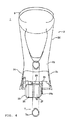
- FIG. 5 is a graph for explaining a power transmission of the hybrid type electric vehicle.
- a hybrid type electric vehicle 1 is shown as an electric vehicle in this embodiment.
- This hybrid type electric vehicle 1 has a front fork 3 supported by a front end portion 2a of a vehicle body 2 for pivotal movement.
- This front fork 3 carries a front wheel which is a steerable wheel 4.
- Steering handle bars 5 extend atop the front fork 3.
- a right and left pair of arms 2c extends rearward in a rear end portion 2b of the vehicle body 2.
- This right and left pair of arms 2c supports an axle 8 of a rear wheel which is a drive wheel 7.
- the rear end portion 2b of the vehicle body 2 has a saddle pedestal 2d extending upward.
- a saddle 9 is attached to this saddle pedestal 2d.
- a vehicle body footboard 2e extends between the front end portion 2a and the rear end portion 2b of the vehicle body 2. As shown in FIG. 2, this vehicle body footboard 2e has a width slightly larger than a width of the right and left pair of arms 2c to ensure a foot space for a rider sitting on the saddle 9.
- an engine 10 is disposed with its cylinder axis extending vertically.
- An air intake system 11 is disposed on a right side of the engine 10 in the vehicle running direction, while an exhaust system 12 is disposed on a left side in the vehicle running direction, both in a plan view.
- the engine 10 is an air-cooled four stroke engine.
- the air intake system 11 has an air intake conduit 11a, a carburetor 11b and an air cleaner 11c.
- the air intake conduit 11a is connected to a right side of a cylinder 10a of the engine 10 in the vehicle running direction.
- the carburetor 11b is positioned in the air intake conduit 11a.
- An air introducing pipe 11d is connected to a rear portion of the air cleaner 11c.
- a fuel tank 14 is coupled with the carburetor 11b through a fuel supply conduit 14a.
- a fuel supply operation is made by an electromagnetic valve 11b1 provided at the carburetor 11b.
- the exhaust system 12 has an exhaust conduit 12a and a muffler 12b.
- the exhaust conduit 12a is connected to a left side of the cylinder 10a of the engine 10 in the vehicle running direction, and the muffler 12b is connected to the exhaust conduit 12a.
- the muffler 12b is disposed with an exhaust gas discharge pipe 12b1 extending downward. As shown in FIG. 3, this exhaust gas discharge pipe 12b1 bends toward the engine side.
- This bending portion 12b2 defines an opening 12b3 positioned below the engine 10, and can discharge exhaust gases toward a portion of the ground under a center of the vehicle body.
- a generator 13 is disposed in the rear of the engine 10.
- the generator 13 is driven by the engine 10 to generate electric power.
- the fuel tank 14 accumulating the fuel for the engine 10 is positioned above the engine 10.
- An engine cooling fan 80 is positioned between the engine 10 and the generator 13.
- a crankshaft 10b of the engine 10 extends in the vehicle running direction.
- This crankshaft 10b and a rotor shaft 13a of the generator 13 are coupled with each other through a coupling 99 in a direction such that respective shaft ends oppose each other. Accordingly, the drive power of the crankshaft 10b of the engine 10 is transmitted to the rotor shaft 13a of the generator 13.
- the crankshaft 10b has the engine cooling fan 80.
- the engine cooling fan 80 is provided and it is positioned between the engine 10 and the generator 13, the engine 10 and the generator 13 can be cooled with the compact and simple structure.
- the vehicle body footboard 2e of the vehicle body 2 has a battery 15 positioned in the rear of the generator 13. Further, a control device A including a hybrid control controller 16 and a motor controller 17 is disposed in the rear of the battery 15. A drive motor 18 is disposed in the rear of the hybrid control controller 16 and the motor controller 17. A sprocket 18a of the drive motor 18 is connected to a sprocket 21 of a wheel 20 of the drive wheel 7 through a chain 19.
- the drive motor 18 is positioned in the rear of the engine 10 in the vehicle running direction to shorten a distance between the drive motor 18 and the axle of the drive wheel 7.
- the power of the drive motor 18 is transmitted to the drive wheel 7 side through the chain 19.
- the power can be transmitted to the drive wheel 7 side through a driveshaft.
- a metal chain normally used for a bicycle, and the like. or a chain made from a rubber belt and reinforced with carbon fibers can be used as the chain 19.
- the battery 15 includes a number of battery cells 15a, a residual battery power detector 15b and a battery temperature detector 15c.
- the battery cells 15a can be nickel hydrogen cells or nickel cadmium cells connected in series.
- the residual battery power detector 15b sends residual battery power information to the hybrid control controller 16, while the battery temperature detector 15c sends battery temperature information to the hybrid control controller 16.
- the hybrid type electric vehicle 1 in this embodiment has the steerable wheel 4 and the drive wheel 7. Between this steerable wheel 4 and the drive wheel 7, the engine 10, the generator 13, the battery 15, the hybrid control controller 16, the motor controller 17 and the drive motor 18 are disposed in the interior of the vehicle body footboard 2e. The electric power generated by the generator 13 driven by the engine 10 and the electric power of the battery 15 are supplied to the drive motor 18. The power of this drive motor 18 is transmitted to the drive wheel 7 so that the vehicle 1 runs.
- the wheel 20 of the drive wheel 7 has a transmission 40.
- the drive motor 18 includes a motor 36 and a transmission 37.
- the transmission 37 varies the rotation of the motor 36 to drive the drive wheel 7.
- the hybrid control controller 16 controls a charge/discharge operation of the battery 15 and an engine speed of the engine 10. As shown in FIG. 5, the controller 16 has an engine control means 16a and a residual power capacity setting means 16b for setting the residual power capacity of the battery 15. An indicating means 50 is connected to the controller 16. The indicating means 50 has a warning lamp, which is not shown, and is positioned adjacent to the steering handle bar 5. When the battery 15 becomes weak, the hybrid control controller 16 turns on the warning lamp. The residual power capacity setting means 16b determines weak battery 15 based upon the residual battery power information of the residual battery power detector 15b.
- the engine control means 16a employs a construction in which the engine control means 16a starts the engine 10 to initiate the power generating/charging operation by the generator 13 when the residual power capacity set by the residual power capacity setting means 16b becomes less than a preset lower limit, while the engine control means 16a stops the engine 10 to discontinue the power generating/charging operation by the generator 13 when the residual power capacity set by the residual power capacity setting means 16b reaches a preset upper limit. That is, when the residual power capacity of the battery 15 becomes less than the lower limit, the engine 10 drives the generator 13 until the residual power capacity reaches the upper limit so that the power generated by the generator 13 is charged into the battery 15.
- the engine control means 16a also employs a construction in which the engine control means 16a stops the engine 10 in a high speed range where a vehicle speed detected by a vehicle speed sensor 51 is over a preset amount. Further, in the construction, the engine control means 16a keeps the engine 10 standstill when the vehicle speed sensor 51 senses that the hybrid type electric vehicle 1 does not run and is standstill.
- An accelerator signal outputted following an operation of the accelerator by the rider is inputted into the motor controller 17.
- the motor controller 17 controls the power of the drive motor 18 so that the power can be generally proportion to the magnitude of the operation of the accelerator.
- the engine 10 in this embodiment starts when the generator 13 drives the crankshaft 10b, and stops when the hybrid control controller 16 opens an ignition circuit.
- a speed range can be broaden because the drive motor 18 incorporates the transmission 37, the axle of the drive wheel 7 has the transmission 40, and the chain 19 transmits the power of the drive motor 18 to the drive wheel side. Accordingly, the drive motor 18, even if it is small, can efficiently achieve the maximum speed while assuring a sufficient start performance.
- the drive motor 18 is positioned in front of a tire periphery 7a of the drive wheel 7 in the vehicle running direction.
- the structures of the transmissions 37, 40 can be compact and simple.
- the transmissions 37, 40 can be incorporated while the weight increase of the drive wheel side restricted to the minimum.
- the transmissions 37, 40 can keep a running performance in a sufficient speed range even though a drive motor having the small maximum power or a small rated power is used, the latest model of the hybrid type electric vehicle 1 which has a small engine prime mover and is energy-saving, clean because of small exhaust gases, compact and light can be constructed.
- the transmissions 37, 40 are automatic transmissions and can further simplify the operation made by the operator. Thus, the operation performance and the running performance can be enhanced. Alternatively, only one of the transmission 37 and the transmission 40 can be the automatic transmission. Also, in this embodiment, a driveshaft can replace the chain 19 to transmit the power of the drive motor 18 to the drive wheel side.
- the engine 10, the generator 13, the battery 15, the control device A, the drive motor 18 are positioned in this order, fore to aft in the advance direction, and in series in the interior of the vehicle body foot board 2e; thereby, the vehicle body can be slim. Accordingly, air resistance of the vehicle body can be drastically reduced.
- the engine 10, the generator 13, the battery 15, the control device (A) and the drive motor 18 are linearly positioned, conduits and wirings connected to those components can have the minimum lengths. Electrical resistance also can be minimized together with the minimum lengths of the wirings.
- the vehicle body footboard 2e is positioned lower than a line L1 connecting upper ends of the steerable wheel 4 and the drive wheel 7 to each other. Thereby, the air resistance of the vehicle body can be drastically reduced.
- the vehicle body footboard 2e has a cooling wind inlet opening 90 for cooling wind positioned at a side portion on the air intake system side, another cooling wind inlet opening 91 positioned above and in front of the engine, and a further cooling wind inlet opening 92 positioned below the drive motor. As shown in FIG. 3, the vehicle body footboard 2e has a still further cooling wind inlet opening 96 positioned below the air intake system, and has a cooling wind discharge opening 95 through which the cooling wind after cooling the components is discharged positioned below the exhaust system.
- the interior of the vehicle body footboard 2e has a negative pressure because the engine cooling fan 80 operates.
- the cooling wind is introduced through the cooling wind inlet opening 90 from the side portion on the air intake system side, through the cooling wind inlet opening 91 from the location above and in front of the engine, and through the cooling wind inlet opening 96 from the location below the air intake system.
- the cooling wind is introduced through the cooling wind inlet opening 92 from the location below the drive motor. The cooling wind cools the drive motor 18, the control device A, the battery 15, the generator 13 and the engine 10.
- the cooling wind also cools the exhaust conduit 12a and the muffler 12b, which forms the exhaust system 12, in this order, i.e., from the component which has a lower temperature.
- the cooling efficiency thus can be improved. Because the sufficient cooling operation can be made with the simple structure, such a compact, light and inexpensive hybrid vehicle can be constructed.
- the electric vehicle includes a residual battery power detecting means 201 formed with the residual battery power detector 15b for detecting a residual power capacity of the battery 15, and a motor control means 200 for lowering a voltage of an accelerator output signal outputted in response to a rotational angle of an accelerator 5a to be less than a voltage given under a condition that the residual power capacity is at or more than a preset lower limit, when the residual power capacity becomes less than the lower limit, so as to control a rotational speed of the drive motor 18.
- a residual battery power detecting means 201 formed with the residual battery power detector 15b for detecting a residual power capacity of the battery 15, and a motor control means 200 for lowering a voltage of an accelerator output signal outputted in response to a rotational angle of an accelerator 5a to be less than a voltage given under a condition that the residual power capacity is at or more than a preset lower limit, when the residual power capacity becomes less than the lower limit, so as to control a rotational speed of the drive motor 18.
- the hybrid control controller 16 has the motor control means 200, and the battery 15 has the residual battery power detecting means 201.
- the hybrid control controller 16 can have the residual battery power detecting means 201.
- the motor control means 200 makes a voltage v of the accelerator output signal larger in response to a rotational angle ⁇ of the accelerator 5a to control the rotational speed of the drive motor 18.
- This rotational speed control is made in accordance with a control characteristic line K1, and the voltage v reaches the maximum at a preset accelerator rotational angle ⁇ .
- the rider rotates the accelerator 5a approximately 0 to 30 degrees to control the rotational speed of the drive motor 18.
- the motor control means 200 controls the rotational speed in accordance with the control characteristic line K2. That is, if a running speed H1 corresponding to 10 degrees of the rotational angle ⁇ of the accelerator 5a in the control of the control characteristic line K1 needs to be maintained, the rotational angle ⁇ of the accelerator 5a is required to be 20 degrees in the control of the control characteristic line K2. This angle means that the rotation of the accelerator 5a becomes larger.
- the voltage of the accelerator output signal outputted in response to the rotational angle of the accelerator 5a is lowered to be less than the voltage given under the condition that the residual power capacity is at or more than the lower limit so as to control the rotational speed of the drive motor 18.
- the rotation of the accelerator 5a needs to be larger than the rotation made under the condition that the residual power capacity is at or more than the lower limit to keep a certain running speed.
- the residual power capacity of the battery 15 can be certainly transmitted to the rider as the response from the accelerator 5a without any indications on a meter panel or the like.
- a rider of a motorcycle needs to have much attention to a forward location in comparison with a driver of a four wheeled vehicle.
- the response of the accelerator is more useful to certainly transmitted the residual power capacity of the battery to the rider than the indication by the panel.
- the power output can be restricted in proportion to a residual amount before starting power generation/charging operations to manage the battery power capacity.
- the electric vehicle includes a residual fuel amount detecting means 210 for detecting a residual fuel amount of the fuel tank 14, and the motor control means 200 for lowering the voltage of the accelerator output signal outputted in response to the rotational angle of the accelerator 5a to be less than a voltage given under a condition that the residual fuel amount is at or more than a preset lower limit, when the residual fuel amount becomes less than the lower limit, so as to control the rotational speed of the drive motor 18.
- the hybrid control controller 16 has the motor control means 200, and the fuel tank 14 has the residual fuel amount detecting means 210.
- the motor control means 200 controls the rotational speed in accordance with the control characteristic line K2. That is, if the running speed H1 corresponding to 10 degrees of the rotational angle ⁇ of the accelerator 5a in the control of the control characteristic line K1 needs to be maintained, the rotational angle ⁇ of the accelerator 5a is required to be 20 degrees in the control of the control characteristic line K2. This angle means that the rotation of the accelerator 5a becomes larger.
- the voltage of the accelerator output signal outputted in response to the rotational angle of the accelerator 5a is lowered to be less than the voltage given under the condition that the residual fuel amount is at or more than the lower limit so as to control the rotational speed of the drive motor 18.
- the rotation of the accelerator 5a needs to be larger than the rotation made under the condition that the residual power capacity is at or more than the lower limit to keep a certain running speed.
- the residual fuel amount can be certainly transmitted to the rider as the response from the accelerator 5a without any indications on a meter panel or the like.
- a rider of a motorcycle needs to have much attention to a forward location in comparison with a driver of a four wheeled vehicle.
- the response of the accelerator is more useful to certainly inform the residual fuel amount to the rider than the indication by the panel.
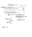
- the electric vehicle includes an abnormality detecting means 220 for detecting abnormality of the vehicle, and the motor control means 200 for lowering the maximum voltage of the accelerator output signal outputted in response to the rotational angle of the accelerator 5a to be less than the maximum voltage given under a normal condition, when the abnormality is detected, so as to control the rotational speed of the drive motor 18.
- the hybrid control controller 16 has the motor control means 200, and the engine 10 or the like has the abnormality detecting means 220.
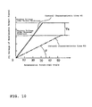
- the abnormality detecting means 220 detects abnormality such as, for example, an engine temperature, insufficiency of the fuel or the weak battery. As shown in FIG. 10, when the abnormality is detected, the motor control means 200 controls the rotational speed in accordance with the control characteristic line K3 to lower the maximum voltage of the accelerator output signal outputted in response to the rotational angle of the accelerator 5a to be less than the preset voltage.
- the voltage of the accelerator output signal outputted in response to the rotational angle of the accelerator 5a is lowered to be less than the voltage given under the normal condition so as to control the rotational speed of the drive motor 18.
- the maximum running speed that can be given under the normal condition is not obtained.
- the abnormality thus can be certainly transmitted to the rider without any indications on a meter panel.
- a rider of a motorcycle needs to have much attention to a forward location in comparison with a driver of a four wheeled vehicle.
- the response of the accelerator is more useful to certainly inform the abnormality to the rider than the indication by the panel.
- the electric vehicle includes a vehicle state detecting means 230 for detecting a vehicle state, and an engine control means 16a for changing an engine speed of the engine 10 in response to a detection result of the vehicle state.
- the hybrid control controller 16 has the engine control means 16a, and the engine 10 or the like has the vehicle state detecting means 230.
- the vehicle state detecting means 230 detects the vehicle state such as, for example, the vehicle speed, the engine temperature, the residual fuel amount or the battery condition.
- the engine control means 16a gives wavering rotational fluctuations in a normal operation, although conventionally only a preset engine speed is given based upon a general setting.
- the rotational period fluctuation is controlled as follows, for example.
- a wavering rotational fluctuation as a period which is almost equal to the human's heartbeat is given to the engine speed in the normal operation.
- the period is elongated when the vehicle ascends an upslope, while the period is shorten when the vehicle descends a down slope.
- no wavering rotational fluctuation control is made in an acceleration operation and in a deceleration operation. In this running speed control, modes which can be selected in accordance with preference of the rider can be prepared.
- the engine speed of the engine 10 is changed in response to the detection result of the vehicle state; thereby, vibrations and sounds of the engine 10 are intentionally changed in response to the vehicle state (a vehicle speed, a temperature, a residual gasoline amount, a battery condition, etc.) to be transmitted to the rider.
- the vehicle state a vehicle speed, a temperature, a residual gasoline amount, a battery condition, etc.
- the engine speed can be increased, or the engine speed can have the periodic change and the period is shorten so that the rider can feel the driving state.
- the vehicle condition can be transmitted to the rider as sensory or intuitive information. The information thus can be transmitted to the rider without giving uneasiness.
- This invention is applicable to an electric vehicle running by driving a drive motor with generated electric power of a generator driven by an engine and with electric power of a battery.
Landscapes
- Engineering & Computer Science (AREA)
- Power Engineering (AREA)
- Transportation (AREA)
- Mechanical Engineering (AREA)
- Life Sciences & Earth Sciences (AREA)
- Sustainable Development (AREA)
- Sustainable Energy (AREA)
- Electric Propulsion And Braking For Vehicles (AREA)
- Hybrid Electric Vehicles (AREA)
- Arrangement Or Mounting Of Propulsion Units For Vehicles (AREA)
- Control Of Vehicle Engines Or Engines For Specific Uses (AREA)
Abstract
[Problem to be Solved] To assist a running sense to provide a rider with easiness
[Solution] In an electric vehicle running by driving a drive motor 18 with generated electric power of a generator 13 driven by an engine 10 and with electric power of a battery 15, the electric vehicle includes a residual battery power detecting means 201 for detecting a residual power capacity of the battery 15, and a motor control means 200 for lowering a voltage of an accelerator output signal outputted in response to a rotational angle of an accelerator 5a to be less than a voltage given under a condition that the residual power capacity is at or more than a preset lower limit, when the residual power capacity becomes less than the lower limit, so as to control a rotational speed of the drive motor 18.
Description
- This invention relates to an electric vehicle running by driving a drive motor with generated electric power of a generator driven by an engine and with electric power of a battery.
- Conventionally, some electric vehicles are hybrid type electric vehicles incorporating a generator of an engine drive type for charging a battery while running to supply electric power to a drive motor driving a drive wheel. Some of this type of vehicles have a structure in which the generated electric power of the generator and the electric power of the battery are supplied to the drive motor so as to run only with the power of this drive motor (for example, see Patent Document 1).
- Patent Document 1: JP-A-2001-105899 (pages 1-9, FIGs. 1-11)
- If these vehicles employ a control system that controls a vehicle speed by a rider holding and rotating an accelerator grip, which conventional engine drive vehicles typically have, sound is smaller than the engine drive vehicles and is quieter in the running state. These vehicles thus can bring some uneasiness to the rider.
- This is because the rider has no element of "sound" of the engine following an operation of the accelerator grip and loses one of large elements of a running sense. Consequently, the rider can have harder uneasiness.
- This invention is made under the circumstances, and an object thereof is to provide a hybrid type electric vehicle that can assist a running sense to provide a rider with easiness.
- In order to solve the problem and to achieve the object, this invention is constructed as follows:
- In accordance with an aspect of the invention recited in
Claim 1, in an electric vehicle running by driving a drive motor with generated electric power of a generator driven by an engine and with electric power of a battery, the electric vehicle includes a residual battery power detecting means for detecting a residual power capacity of the battery, and a motor control means for lowering a voltage of an accelerator output signal outputted in response to a rotational angle of an accelerator to be less than a voltage given under a condition that the residual power capacity is at or more than a preset lower limit, when the residual power capacity becomes less than the lower limit, so as to control a rotational speed of the drive motor. - In accordance with another aspect of the invention recited in
Claim 2, in an electric vehicle running by driving a drive motor with generated electric power of a generator driven by an engine and with electric power of a battery, the electric vehicle includes a residual fuel amount detecting means for detecting a residual fuel amount of a fuel tank, and a motor control means for lowering a voltage of an accelerator output signal outputted in response to a rotational angle of an accelerator to be less than a voltage given under a condition that the residual fuel amount is at or more than a preset lower limit, when the residual fuel amount becomes less than the lower limit, so as to control a rotational speed of the drive motor. - In accordance with a further aspect of the invention recited in
Claim 3, in an electric vehicle running by driving a drive motor with generated electric power of a generator driven by an engine and with electric power of a battery, the electric vehicle includes an abnormality detecting means for detecting abnormality of the vehicle, and a motor control means for lowering the maximum voltage of an accelerator output signal outputted in response to a rotational angle of an accelerator to be less than the maximum voltage given under a normal condition, when the abnormality is detected, so as to control a rotational speed of the drive motor. - In accordance with a further aspect of the invention recited in Claim 4, in an electric vehicle running by driving a drive motor with generated electric power of a generator driven by an engine and with electric power of a battery, the electric vehicle includes a vehicle state detecting means for detecting a vehicle state, and an engine control means for changing an engine speed of the engine in response to a detection result of the vehicle state.
- According to the construction, this invention has the following effects.
- In the aspect of the invention recited in
Claim 1, when the residual power capacity becomes less than the preset lower limit, the voltage of the accelerator output signal outputted in response to the rotational angle of the accelerator is lowered to be less than the voltage given under the condition that the residual power capacity is at or more than the lower limit so as to control the rotational speed of the drive motor. In order to keep a preset running speed, a rotation of the accelerator needs to be larger than the rotation given under the condition that the residual power capacity is at or more than the preset lower limit. As thus constructed, the residual power capacity of the battery can be certainly transmitted to the rider as the response from the accelerator without any indications on a meter panel or the like. Particularly, a rider of a motorcycle needs to have much attention to a forward location in comparison with a driver of a four wheeled vehicle. For the rider's concentration to the drive of the vehicle, the response of the accelerator is more useful to certainly inform the residual power capacity of the battery to the rider than the indication by the panel. Also, if the electric power is consumed over the generator's power capacity, the power output can be restricted in proportion to a residual amount before starting power generation/charging operations to manage the battery power capacity. - In the aspect of the invention recited in
Claim 2, when the residual fuel amount becomes less than the preset lower limit, the voltage of the accelerator output signal outputted in response to the rotational angle of the accelerator is lowered to be less than the voltage given under the condition that the residual fuel amount is at or more than the lower limit so as to control the rotational speed of the drive motor. In order to keep the preset running speed, a rotation of the accelerator needs to be larger than the rotation given under the condition that the residual fuel amount is at or more than the preset lower limit. As thus constructed, the residual fuel amount can be certainly transmitted to the rider as the response from the accelerator without any indications on the meter panel or the like. Particularly, the rider of the motorcycle needs to have much attention to a forward location in comparison with the rider of the four wheeled vehicle. For the rider's concentration to the drive of the vehicle, the response of the accelerator is more useful to certainly inform the residual fuel amount to the driver than the indication by the panel. - In the aspect of the invention recited in
Claim 3, when the abnormality is detected, the maximum voltage of the accelerator output signal outputted in response to the rotational angle of the accelerator is lowered to be less than the maximum voltage given under the normal condition so as to control the rotational speed of the drive motor. Because, when the abnormality occurs, the maximum voltage of the normal condition cannot be obtained even though the rotational angle of the accelerator becomes larger, the abnormality of the vehicle under the running condition can be certainly transmitted to the rider without any indications on the meter panel or the like. Particularly, the rider of the motorcycle needs to have much attention to a forward location in comparison with the driver of the four wheeled vehicle. For the rider's concentration to the drive of the vehicle, the response of the accelerator is more useful to certainly inform the abnormality to the rider than the indication by the panel. - In the aspect of the invention recited in Claim 4, the engine speed of the engine is changed in response to the detection result of the vehicle state; thereby, vibrations and sounds of the engine are intentionally changed in response to the vehicle state (a vehicle speed, a temperature, a residual gasoline amount, a battery condition, etc.) to be transmitted to the rider. For instance, when the vehicle comes to an upslope and runs with both of the power of the battery and the power generated by the engine, if the residual battery power approaches the preset lower limit, the engine speed can be increased, or the engine speed can have a periodic change and the period is shorten so that the rider can feel the driving state. Thereby, the vehicle condition can be transmitted to the rider as sensory or intuitive information. The information thus can be transmitted to the rider without giving uneasiness.
- Although an embodiment of the electric vehicle of this invention will be described below, this invention is not limited to this embodiment. Also, this embodiment of the invention is the most preferable one, and terms of this invention are not limited to those of the embodiment.
- FIG. 1 is a side elevational view of a hybrid type electric vehicle, FIG. 2 is a cross sectional view taken along the line II-II of FIG. 1, FIG. 3 is a cross sectional view taken along the line III-III of FIG. 1, FIG. 4 is a cross sectional view taken along the line IV-IV of FIG. 1, and FIG. 5 is a graph for explaining a power transmission of the hybrid type electric vehicle.
Through FIG. 1 to FIG. 4, a hybrid typeelectric vehicle 1 is shown as an electric vehicle in this embodiment. This hybrid typeelectric vehicle 1 has afront fork 3 supported by afront end portion 2a of avehicle body 2 for pivotal movement. Thisfront fork 3 carries a front wheel which is a steerable wheel 4. Steering handle bars 5 extend atop thefront fork 3. - A right and left pair of
arms 2c extends rearward in arear end portion 2b of thevehicle body 2. This right and left pair ofarms 2c supports anaxle 8 of a rear wheel which is adrive wheel 7. Therear end portion 2b of thevehicle body 2 has asaddle pedestal 2d extending upward. Asaddle 9 is attached to thissaddle pedestal 2d. - A
vehicle body footboard 2e extends between thefront end portion 2a and therear end portion 2b of thevehicle body 2. As shown in FIG. 2, thisvehicle body footboard 2e has a width slightly larger than a width of the right and left pair ofarms 2c to ensure a foot space for a rider sitting on thesaddle 9. - In the interior of the
vehicle body footboard 2e of thisvehicle body 2, anengine 10 is disposed with its cylinder axis extending vertically. Anair intake system 11 is disposed on a right side of theengine 10 in the vehicle running direction, while anexhaust system 12 is disposed on a left side in the vehicle running direction, both in a plan view. Theengine 10 is an air-cooled four stroke engine. - As shown in FIG. 2, the
air intake system 11 has an air intake conduit 11a, acarburetor 11b and anair cleaner 11c. The air intake conduit 11a is connected to a right side of acylinder 10a of theengine 10 in the vehicle running direction. Thecarburetor 11b is positioned in the air intake conduit 11a. Anair introducing pipe 11d is connected to a rear portion of theair cleaner 11c. Afuel tank 14 is coupled with thecarburetor 11b through afuel supply conduit 14a. A fuel supply operation is made by an electromagnetic valve 11b1 provided at thecarburetor 11b. - The
exhaust system 12 has anexhaust conduit 12a and amuffler 12b. Theexhaust conduit 12a is connected to a left side of thecylinder 10a of theengine 10 in the vehicle running direction, and themuffler 12b is connected to theexhaust conduit 12a. Themuffler 12b is disposed with an exhaust gas discharge pipe 12b1 extending downward. As shown in FIG. 3, this exhaust gas discharge pipe 12b1 bends toward the engine side. This bending portion 12b2 defines an opening 12b3 positioned below theengine 10, and can discharge exhaust gases toward a portion of the ground under a center of the vehicle body. - Also, as shown in FIG. 2, a
generator 13 is disposed in the rear of theengine 10. Thegenerator 13 is driven by theengine 10 to generate electric power. Thefuel tank 14 accumulating the fuel for theengine 10 is positioned above theengine 10. - An
engine cooling fan 80 is positioned between theengine 10 and thegenerator 13. Acrankshaft 10b of theengine 10 extends in the vehicle running direction. Thiscrankshaft 10b and arotor shaft 13a of thegenerator 13 are coupled with each other through acoupling 99 in a direction such that respective shaft ends oppose each other. Accordingly, the drive power of thecrankshaft 10b of theengine 10 is transmitted to therotor shaft 13a of thegenerator 13. Thecrankshaft 10b has theengine cooling fan 80. - Because the
engine cooling fan 80 is provided and it is positioned between theengine 10 and thegenerator 13, theengine 10 and thegenerator 13 can be cooled with the compact and simple structure. - Also, the
vehicle body footboard 2e of thevehicle body 2 has abattery 15 positioned in the rear of thegenerator 13. Further, a control device A including ahybrid control controller 16 and amotor controller 17 is disposed in the rear of thebattery 15. Adrive motor 18 is disposed in the rear of thehybrid control controller 16 and themotor controller 17. Asprocket 18a of thedrive motor 18 is connected to asprocket 21 of awheel 20 of thedrive wheel 7 through achain 19. - The
drive motor 18 is positioned in the rear of theengine 10 in the vehicle running direction to shorten a distance between thedrive motor 18 and the axle of thedrive wheel 7. - As thus discussed, the power of the
drive motor 18 is transmitted to thedrive wheel 7 side through thechain 19. The power, however, can be transmitted to thedrive wheel 7 side through a driveshaft. A metal chain normally used for a bicycle, and the like. or a chain made from a rubber belt and reinforced with carbon fibers can be used as thechain 19. - As shown in FIG. 5, the
battery 15 includes a number ofbattery cells 15a, a residualbattery power detector 15b and abattery temperature detector 15c. Thebattery cells 15a can be nickel hydrogen cells or nickel cadmium cells connected in series. The residualbattery power detector 15b sends residual battery power information to thehybrid control controller 16, while thebattery temperature detector 15c sends battery temperature information to thehybrid control controller 16. - The hybrid type
electric vehicle 1 in this embodiment has the steerable wheel 4 and thedrive wheel 7. Between this steerable wheel 4 and thedrive wheel 7, theengine 10, thegenerator 13, thebattery 15, thehybrid control controller 16, themotor controller 17 and thedrive motor 18 are disposed in the interior of thevehicle body footboard 2e. The electric power generated by thegenerator 13 driven by theengine 10 and the electric power of thebattery 15 are supplied to thedrive motor 18. The power of thisdrive motor 18 is transmitted to thedrive wheel 7 so that thevehicle 1 runs. Thewheel 20 of thedrive wheel 7 has atransmission 40. - As shown in FIGs. 2, 4 and 5, the
drive motor 18 according to this embodiment includes amotor 36 and atransmission 37. Thetransmission 37 varies the rotation of themotor 36 to drive thedrive wheel 7. - The
hybrid control controller 16 controls a charge/discharge operation of thebattery 15 and an engine speed of theengine 10. As shown in FIG. 5, thecontroller 16 has an engine control means 16a and a residual power capacity setting means 16b for setting the residual power capacity of thebattery 15. An indicating means 50 is connected to thecontroller 16. The indicating means 50 has a warning lamp, which is not shown, and is positioned adjacent to the steering handle bar 5. When thebattery 15 becomes weak, thehybrid control controller 16 turns on the warning lamp. The residual power capacity setting means 16b determinesweak battery 15 based upon the residual battery power information of the residualbattery power detector 15b. - The engine control means 16a employs a construction in which the engine control means 16a starts the
engine 10 to initiate the power generating/charging operation by thegenerator 13 when the residual power capacity set by the residual power capacity setting means 16b becomes less than a preset lower limit, while the engine control means 16a stops theengine 10 to discontinue the power generating/charging operation by thegenerator 13 when the residual power capacity set by the residual power capacity setting means 16b reaches a preset upper limit. That is, when the residual power capacity of thebattery 15 becomes less than the lower limit, theengine 10 drives thegenerator 13 until the residual power capacity reaches the upper limit so that the power generated by thegenerator 13 is charged into thebattery 15. - The engine control means 16a also employs a construction in which the engine control means 16a stops the
engine 10 in a high speed range where a vehicle speed detected by avehicle speed sensor 51 is over a preset amount. Further, in the construction, the engine control means 16a keeps theengine 10 standstill when thevehicle speed sensor 51 senses that the hybrid typeelectric vehicle 1 does not run and is standstill. - An accelerator signal outputted following an operation of the accelerator by the rider is inputted into the
motor controller 17. Themotor controller 17 controls the power of thedrive motor 18 so that the power can be generally proportion to the magnitude of the operation of the accelerator. - The
engine 10 in this embodiment starts when thegenerator 13 drives thecrankshaft 10b, and stops when thehybrid control controller 16 opens an ignition circuit. - In this embodiment, a speed range can be broaden because the
drive motor 18 incorporates thetransmission 37, the axle of thedrive wheel 7 has thetransmission 40, and thechain 19 transmits the power of thedrive motor 18 to the drive wheel side. Accordingly, thedrive motor 18, even if it is small, can efficiently achieve the maximum speed while assuring a sufficient start performance. Thedrive motor 18 is positioned in front of atire periphery 7a of thedrive wheel 7 in the vehicle running direction. - Because both of the drive motor and the drive wheel have the
transmissions transmissions transmissions - Because the
transmissions electric vehicle 1 which has a small engine prime mover and is energy-saving, clean because of small exhaust gases, compact and light can be constructed. - The
transmissions transmission 37 and thetransmission 40 can be the automatic transmission. Also, in this embodiment, a driveshaft can replace thechain 19 to transmit the power of thedrive motor 18 to the drive wheel side. - In the hybrid type
electric vehicle 1 of this embodiment, theengine 10, thegenerator 13, thebattery 15, the control device A, thedrive motor 18 are positioned in this order, fore to aft in the advance direction, and in series in the interior of the vehiclebody foot board 2e; thereby, the vehicle body can be slim. Accordingly, air resistance of the vehicle body can be drastically reduced. In addition, because theengine 10, thegenerator 13, thebattery 15, the control device (A) and thedrive motor 18 are linearly positioned, conduits and wirings connected to those components can have the minimum lengths. Electrical resistance also can be minimized together with the minimum lengths of the wirings. - As shown in FIG. 1, the
vehicle body footboard 2e is positioned lower than a line L1 connecting upper ends of the steerable wheel 4 and thedrive wheel 7 to each other. Thereby, the air resistance of the vehicle body can be drastically reduced. - The
vehicle body footboard 2e has a cooling wind inlet opening 90 for cooling wind positioned at a side portion on the air intake system side, another cooling wind inlet opening 91 positioned above and in front of the engine, and a further cooling wind inlet opening 92 positioned below the drive motor. As shown in FIG. 3, thevehicle body footboard 2e has a still further cooling wind inlet opening 96 positioned below the air intake system, and has a coolingwind discharge opening 95 through which the cooling wind after cooling the components is discharged positioned below the exhaust system. - When the hybrid type
electric vehicle 1 runs, the interior of thevehicle body footboard 2e has a negative pressure because theengine cooling fan 80 operates. Thus, as shown in FIG. 3, the cooling wind is introduced through the cooling wind inlet opening 90 from the side portion on the air intake system side, through the cooling wind inlet opening 91 from the location above and in front of the engine, and through the cooling wind inlet opening 96 from the location below the air intake system. Also, as shown in FIG. 2, the cooling wind is introduced through the cooling wind inlet opening 92 from the location below the drive motor. The cooling wind cools thedrive motor 18, the control device A, thebattery 15, thegenerator 13 and theengine 10. The cooling wind also cools theexhaust conduit 12a and themuffler 12b, which forms theexhaust system 12, in this order, i.e., from the component which has a lower temperature. The cooling efficiency thus can be improved. Because the sufficient cooling operation can be made with the simple structure, such a compact, light and inexpensive hybrid vehicle can be constructed. - In the aspect of the invention recited in
Claim 1, as shown in FIG. 6, the electric vehicle includes a residual battery power detecting means 201 formed with the residualbattery power detector 15b for detecting a residual power capacity of thebattery 15, and a motor control means 200 for lowering a voltage of an accelerator output signal outputted in response to a rotational angle of anaccelerator 5a to be less than a voltage given under a condition that the residual power capacity is at or more than a preset lower limit, when the residual power capacity becomes less than the lower limit, so as to control a rotational speed of thedrive motor 18. - In this embodiment, the
hybrid control controller 16 has the motor control means 200, and thebattery 15 has the residual batterypower detecting means 201. However, thehybrid control controller 16 can have the residual batterypower detecting means 201. - As shown in FIG. 7, the motor control means 200 makes a voltage v of the accelerator output signal larger in response to a rotational angle θ of the
accelerator 5a to control the rotational speed of thedrive motor 18. This rotational speed control is made in accordance with a control characteristic line K1, and the voltage v reaches the maximum at a preset accelerator rotational angle θ. Normally, the rider rotates theaccelerator 5a approximately 0 to 30 degrees to control the rotational speed of thedrive motor 18. - When the residual power capacity becomes less than the lower limit, the motor control means 200 controls the rotational speed in accordance with the control characteristic line K2. That is, if a running speed H1 corresponding to 10 degrees of the rotational angle θ of the
accelerator 5a in the control of the control characteristic line K1 needs to be maintained, the rotational angle θ of theaccelerator 5a is required to be 20 degrees in the control of the control characteristic line K2. This angle means that the rotation of theaccelerator 5a becomes larger. - 1 As thus discussed, when the residual power capacity of the
battery 15 becomes less than the preset lower limit, the voltage of the accelerator output signal outputted in response to the rotational angle of theaccelerator 5a is lowered to be less than the voltage given under the condition that the residual power capacity is at or more than the lower limit so as to control the rotational speed of thedrive motor 18. Thus, when the residual power capacity of thebattery 15 becomes less than the preset lower limit, the rotation of theaccelerator 5a needs to be larger than the rotation made under the condition that the residual power capacity is at or more than the lower limit to keep a certain running speed. - Accordingly, the residual power capacity of the
battery 15 can be certainly transmitted to the rider as the response from theaccelerator 5a without any indications on a meter panel or the like. Particularly, a rider of a motorcycle needs to have much attention to a forward location in comparison with a driver of a four wheeled vehicle. For the rider's concentration to the drive of the vehicle, the response of the accelerator is more useful to certainly transmitted the residual power capacity of the battery to the rider than the indication by the panel. Also, if the electric power is consumed over the generator's power capacity, the power output can be restricted in proportion to a residual amount before starting power generation/charging operations to manage the battery power capacity. - In the aspect of the invention recited in
Claim 2, as shown in FIG. 8, the electric vehicle includes a residual fuel amount detecting means 210 for detecting a residual fuel amount of thefuel tank 14, and the motor control means 200 for lowering the voltage of the accelerator output signal outputted in response to the rotational angle of theaccelerator 5a to be less than a voltage given under a condition that the residual fuel amount is at or more than a preset lower limit, when the residual fuel amount becomes less than the lower limit, so as to control the rotational speed of thedrive motor 18. - In this embodiment, the
hybrid control controller 16 has the motor control means 200, and thefuel tank 14 has the residual fuelamount detecting means 210. - As shown in FIG. 7, in this embodiment, when the residual fuel amount becomes less than the lower limit, the motor control means 200 controls the rotational speed in accordance with the control characteristic line K2. That is, if the running speed H1 corresponding to 10 degrees of the rotational angle θ of the
accelerator 5a in the control of the control characteristic line K1 needs to be maintained, the rotational angle θ of theaccelerator 5a is required to be 20 degrees in the control of the control characteristic line K2. This angle means that the rotation of theaccelerator 5a becomes larger. - As thus discussed, when the residual fuel amount becomes less than the preset lower limit, the voltage of the accelerator output signal outputted in response to the rotational angle of the
accelerator 5a is lowered to be less than the voltage given under the condition that the residual fuel amount is at or more than the lower limit so as to control the rotational speed of thedrive motor 18. Thus, when the residual fuel amount becomes less than the preset lower limit, the rotation of theaccelerator 5a needs to be larger than the rotation made under the condition that the residual power capacity is at or more than the lower limit to keep a certain running speed. - Accordingly, the residual fuel amount can be certainly transmitted to the rider as the response from the
accelerator 5a without any indications on a meter panel or the like. Particuiariy, a rider of a motorcycle needs to have much attention to a forward location in comparison with a driver of a four wheeled vehicle. For the rider's concentration to the drive of the vehicle, the response of the accelerator is more useful to certainly inform the residual fuel amount to the rider than the indication by the panel. - In the aspect of the invention recited in
Claim 3, as shown in FIG. 9, the electric vehicle includes an abnormality detecting means 220 for detecting abnormality of the vehicle, and the motor control means 200 for lowering the maximum voltage of the accelerator output signal outputted in response to the rotational angle of theaccelerator 5a to be less than the maximum voltage given under a normal condition, when the abnormality is detected, so as to control the rotational speed of thedrive motor 18. - In this embodiment, the
hybrid control controller 16 has the motor control means 200, and theengine 10 or the like has theabnormality detecting means 220. - The abnormality detecting means 220 detects abnormality such as, for example, an engine temperature, insufficiency of the fuel or the weak battery. As shown in FIG. 10, when the abnormality is detected, the motor control means 200 controls the rotational speed in accordance with the control characteristic line K3 to lower the maximum voltage of the accelerator output signal outputted in response to the rotational angle of the
accelerator 5a to be less than the preset voltage. - As thus discussed, when the abnormality is detected, the voltage of the accelerator output signal outputted in response to the rotational angle of the
accelerator 5a is lowered to be less than the voltage given under the normal condition so as to control the rotational speed of thedrive motor 18. Thus, under the abnormal condition, the maximum running speed that can be given under the normal condition is not obtained. The abnormality thus can be certainly transmitted to the rider without any indications on a meter panel. Particularly, a rider of a motorcycle needs to have much attention to a forward location in comparison with a driver of a four wheeled vehicle. For the rider's concentration to the drive of the vehicle, the response of the accelerator is more useful to certainly inform the abnormality to the rider than the indication by the panel. - In the aspect of the invention recited in Claim 4, as shown in FIG. 11, the electric vehicle includes a vehicle state detecting means 230 for detecting a vehicle state, and an engine control means 16a for changing an engine speed of the
engine 10 in response to a detection result of the vehicle state. In this embodiment, thehybrid control controller 16 has the engine control means 16a, and theengine 10 or the like has the vehiclestate detecting means 230. - The vehicle state detecting means 230 detects the vehicle state such as, for example, the vehicle speed, the engine temperature, the residual fuel amount or the battery condition. As shown in FIG. 12, for example, the engine control means 16a gives wavering rotational fluctuations in a normal operation, although conventionally only a preset engine speed is given based upon a general setting. The rotational period fluctuation is controlled as follows, for example.
- For example, a wavering rotational fluctuation as a period which is almost equal to the human's heartbeat is given to the engine speed in the normal operation. The period is elongated when the vehicle ascends an upslope, while the period is shorten when the vehicle descends a down slope. Also, no wavering rotational fluctuation control is made in an acceleration operation and in a deceleration operation. In this running speed control, modes which can be selected in accordance with preference of the rider can be prepared.
- As thus discussed, the engine speed of the
engine 10 is changed in response to the detection result of the vehicle state; thereby, vibrations and sounds of theengine 10 are intentionally changed in response to the vehicle state (a vehicle speed, a temperature, a residual gasoline amount, a battery condition, etc.) to be transmitted to the rider. For instance, when the vehicle comes to an upslope and runs with both of the power of the battery and the power generated by the engine, if the residual battery power approaches the preset lower limit, the engine speed can be increased, or the engine speed can have the periodic change and the period is shorten so that the rider can feel the driving state. Thereby, the vehicle condition can be transmitted to the rider as sensory or intuitive information. The information thus can be transmitted to the rider without giving uneasiness. - This invention is applicable to an electric vehicle running by driving a drive motor with generated electric power of a generator driven by an engine and with electric power of a battery.
-
- FIG. 1 is a side elevational view of a hybrid type electric vehicle.
- FIG. 2 is a cross sectional view taken along the line II-II of FIG. 1.
- FIG. 3 is a cross sectional view taken along the line III-III of FIG. 1.
- FIG. 4 is a cross sectional view taken along the line IV-IV of FIG. 1.
- FIG. 5 is a graph for explaining a power transmission of the hybrid type electric vehicle.
- FIG. 6 is a block diagram showing a schematic construction of the aspect of the invention recited in
Claim 1. - FIG. 7 is a graph showing a relationship between an accelerator rotational angle and an accelerator output signal.
- FIG. 8 is a block diagram showing a schematic construction of the aspect of the invention recited in
Claim 2. - FIG. 9 is a block diagram showing a schematic construction of the aspect of the invention recited in
Claim 3. - FIG. 10 is a graph showing a relationship between an accelerator rotational angle and an accelerator output signal.
- FIG. 11 is a block diagram showing a schematic construction of the aspect of the invention recited in Claim 4.
- FIG. 12 is a graph showing a condition under which an engine speed is changed in response to a vehicle state.
-
- 1:
- hybrid type electric vehicle
- 2:
- vehicle body
- 4:
- steerable wheel
- 5a:
- accelerator
- 7:
- drive wheel
- 10:
- engine
- 13:
- generator
- 14:
- fuel tank
- 15:
- battery
- 16:
- hybrid control controller
- 17:
- motor controller
- 18:
- drive motor
- 200:
- motor control means
- 201:
- residual battery power detecting means
- 210:
- residual fuel amount detecting means
- 220
- abnormality detecting means
- 230:
- vehicle state detecting means
- A:
- control device
Claims (4)
- An electric vehicle running by driving a drive motor with generated electric power of a generator driven by an engine and with electric power of a battery, the electric vehicle comprises:a residual battery power detecting means for detecting a residual power capacity of the battery; anda motor control means for lowering a voltage of an accelerator output signal outputted in response to a rotational angle of an accelerator to be less than a voltage given under a condition that the residual power capacity is at or more than a preset lower limit, when the residual power capacity becomes less than the lower limit, so as to control a rotational speed of the drive motor.
- An electric vehicle running by driving a drive motor with generated electric power of a generator driven by an engine and with electric power of a battery, the electric vehicle comprises:a residual fuel amount detecting means for detecting a residual fuel amount of a fuel tank; anda motor control means for lowering a voltage of an accelerator output signal outputted in response to a rotational angle of an accelerator to be less than a voltage given under a condition that the residual fuel amount is at or more than a preset lower limit, when the residual fuel amount becomes less than the lower limit, so as to control a rotational speed of the drive motor.
- An electric vehicle running by driving a drive motor with generated electric power of a generator driven by an engine and with electric power of a battery, the electric vehicle comprises:an abnormality detecting means for detecting abnormality of the vehicle; anda motor control means for lowering the maximum voltage of an accelerator output signal outputted in response to a rotational angle of an accelerator to be less than the maximum voltage given under a normal condition, when the abnormality is detected, so as to control a rotational speed of the drive motor.
- An electric vehicle running by driving a drive motor with generated electric power of a generator driven by an engine and with electric power of a battery, the electric vehicle comprises:a vehicle state detecting means for detecting a vehicle state; andan engine control means for changing an engine speed of the engine in response to a detection result of the vehicle state.
Applications Claiming Priority (2)
| Application Number | Priority Date | Filing Date | Title |
|---|---|---|---|
| JP2003375177A JP2005143169A (en) | 2003-11-05 | 2003-11-05 | Electric vehicle |
| PCT/JP2004/015850 WO2005044613A1 (en) | 2003-11-05 | 2004-10-26 | Electric vehicle |
Publications (1)
| Publication Number | Publication Date |
|---|---|
| EP1681197A1 true EP1681197A1 (en) | 2006-07-19 |
Family
ID=34567061
Family Applications (1)
| Application Number | Title | Priority Date | Filing Date |
|---|---|---|---|
| EP04818174A Withdrawn EP1681197A1 (en) | 2003-11-05 | 2004-10-26 | Electric vehicle |
Country Status (5)
| Country | Link |
|---|---|
| US (1) | US7478692B2 (en) |
| EP (1) | EP1681197A1 (en) |
| JP (1) | JP2005143169A (en) |
| CN (1) | CN100445144C (en) |
| WO (1) | WO2005044613A1 (en) |
Cited By (3)
| Publication number | Priority date | Publication date | Assignee | Title |
|---|---|---|---|---|
| WO2018108356A1 (en) * | 2016-12-15 | 2018-06-21 | Jaguar Land Rover Limited | Apparatus and method for controlling a high voltage circuit |
| EP3505437A1 (en) * | 2017-12-28 | 2019-07-03 | Kawasaki Jukogyo Kabushiki Kaisha | Hybrid straddle vehicle |
| WO2021094813A1 (en) * | 2019-11-13 | 2021-05-20 | Zapp Scooters Limited | A seat-supporting structure for mounting on a motorcycle frame |
Families Citing this family (26)
| Publication number | Priority date | Publication date | Assignee | Title |
|---|---|---|---|---|
| JP4667090B2 (en) | 2005-03-16 | 2011-04-06 | ヤマハ発動機株式会社 | Hybrid vehicle drive unit, hybrid vehicle and motorcycle |
| JP4317536B2 (en) | 2005-06-23 | 2009-08-19 | ヤマハ発動機株式会社 | Hybrid motorcycle drive device and hybrid motorcycle equipped with the same |
| JP4577168B2 (en) * | 2005-09-13 | 2010-11-10 | 三菱電機株式会社 | Control device for motor output |
| JP5024811B2 (en) | 2006-03-17 | 2012-09-12 | 国立大学法人静岡大学 | Electric vehicle power supply device |
| JP4674722B2 (en) * | 2006-03-17 | 2011-04-20 | 国立大学法人静岡大学 | Electric vehicle power supply device |
| JP4606362B2 (en) * | 2006-03-29 | 2011-01-05 | 株式会社バンダイナムコゲームス | Engine simulation sound generating apparatus and method |
| JP4293266B2 (en) * | 2007-05-31 | 2009-07-08 | トヨタ自動車株式会社 | Hybrid car |
| JP4822551B2 (en) * | 2007-09-25 | 2011-11-24 | 本田技研工業株式会社 | Electric motorcycle |
| JP4453765B2 (en) * | 2008-02-26 | 2010-04-21 | トヨタ自動車株式会社 | Hybrid vehicle and control method thereof |
| US7610979B1 (en) * | 2008-07-16 | 2009-11-03 | Harley-Davidson Motor Company Group, LLC | Reverse drive system for a three-wheeled vehicle |
| JP4978735B2 (en) * | 2008-11-05 | 2012-07-18 | トヨタ自動車株式会社 | Hybrid vehicle and control method of hybrid vehicle |
| US20110100731A1 (en) * | 2009-10-30 | 2011-05-05 | Hassan M Hassan | Perpetual fuel-free electric vehicle |
| JP5450796B2 (en) * | 2010-03-31 | 2014-03-26 | 本田技研工業株式会社 | Saddle riding type electric vehicle |
| CN102802983B (en) * | 2010-03-31 | 2015-07-15 | 本田技研工业株式会社 | Saddled electric vehicle |
| JP5439298B2 (en) * | 2010-06-30 | 2014-03-12 | 本田技研工業株式会社 | Discharge control device for electric vehicle |
| US8552251B2 (en) | 2010-10-08 | 2013-10-08 | Kimberly-Clark Worldwide, Inc. | Article with health-benefit agent delivery system |
| CN102166948A (en) * | 2011-03-21 | 2011-08-31 | 浙江吉利汽车研究院有限公司 | Power system of series plug-in hybrid power vehicle |
| JP5766102B2 (en) * | 2011-11-22 | 2015-08-19 | 本田技研工業株式会社 | Outboard motor control device |
| DE102013205829A1 (en) * | 2013-04-03 | 2014-10-09 | Bayerische Motoren Werke Aktiengesellschaft | Routing device for vehicles |
| JP2016068799A (en) * | 2014-09-30 | 2016-05-09 | 富士重工業株式会社 | Vehicle control apparatus and vehicle control method |
| US11192604B2 (en) * | 2017-11-02 | 2021-12-07 | Piaggio & C. S.P.A. | Electric drive motorcycle |
| EP3779134B1 (en) * | 2018-03-28 | 2022-11-16 | Honda Motor Co., Ltd. | Motorcycle |
| JP7266669B2 (en) * | 2019-03-19 | 2023-04-28 | 本田技研工業株式会社 | series hybrid motorcycle |
| CN112627973B (en) * | 2021-01-11 | 2022-07-12 | 重庆宗申发动机制造有限公司 | Range extender for motorcycle |
| US12291118B2 (en) | 2021-10-30 | 2025-05-06 | Beta Air, Llc | System and method for managing residual energy in a charging component |
| US11648848B1 (en) | 2021-10-30 | 2023-05-16 | Beta Air, Llc | System and method for managing residual energy for an electric aircraft |
Family Cites Families (128)
| Publication number | Priority date | Publication date | Assignee | Title |
|---|---|---|---|---|
| US3566165A (en) | 1969-05-06 | 1971-02-23 | Gen Motors Corp | Electric vehicle drive motor |
| US3921745A (en) | 1973-07-23 | 1975-11-25 | Mcculloch Corp | Electric bicycle |
| IT1061847B (en) | 1976-06-25 | 1983-04-30 | Piaggio & C Spa | DRIVE WHEEL WITH INTERNAL COMBUSTION ENGINE HOUSED IN ITS INTERNAL S * AZIO |
| JPS58112476A (en) | 1981-12-25 | 1983-07-04 | Toyota Central Res & Dev Lab Inc | multilevel inverter |
| US4536668A (en) | 1982-09-13 | 1985-08-20 | Boyer Robert E | Vehicle mountable electrical generating system |
| GB2185946B (en) | 1985-12-04 | 1989-02-01 | Honda Motor Co Ltd | Reverse drive for small vehicles |
| JPS63107448A (en) | 1986-10-23 | 1988-05-12 | Calsonic Corp | Flat motor |
| US5024113A (en) | 1987-09-19 | 1991-06-18 | Honda Giken Kogyo Kabushiki Kaisha | Reverse drive for vehicle |
| JPH027702A (en) | 1988-06-27 | 1990-01-11 | Sharp Corp | Board connection structure for microwave device |
| JP2769323B2 (en) | 1988-06-29 | 1998-06-25 | アイシン・エィ・ダブリュ株式会社 | Motor drive device with reduction gear and electric vehicle |
| JPH02218865A (en) | 1989-02-20 | 1990-08-31 | Mitsubishi Electric Corp | Coaxial starter |
| JPH0237027A (en) | 1989-05-29 | 1990-02-07 | Seiko Epson Corp | Electric car |
| JPH03215154A (en) | 1990-01-19 | 1991-09-20 | Matsushita Electric Ind Co Ltd | Motor |
| DE4012062A1 (en) | 1990-04-10 | 1991-10-17 | Schlueter Gerd | ELECTRIC DRIVE SYSTEM FOR A VEHICLE |
| EP0678968A3 (en) | 1990-10-09 | 1996-03-20 | Stridsberg Licensing Ab | A reconfigurable electric power train for vehicles. |
| US5144183A (en) | 1990-11-20 | 1992-09-01 | Kollmorgen Corporation | Flat motor of reduced length |
| JP3093782B2 (en) | 1990-11-20 | 2000-10-03 | アイシン・エイ・ダブリュ株式会社 | Wheel motor with reduction gear |
| JP2922633B2 (en) | 1990-11-29 | 1999-07-26 | 三菱電機株式会社 | Disk unit |
| US5087229A (en) | 1991-05-06 | 1992-02-11 | General Motors Corporation | Independently suspended steerable motor wheel apparatus |
| JP3131248B2 (en) * | 1991-08-02 | 2001-01-31 | 本田技研工業株式会社 | Running performance control device for electric vehicles |
| CA2088651A1 (en) | 1992-02-07 | 1993-08-08 | Shigenori Kinoshita | Inverter for electric vehicle |
| US5280223A (en) * | 1992-03-31 | 1994-01-18 | General Electric Company | Control system for an electrically propelled traction vehicle |
| JPH05300712A (en) | 1992-04-22 | 1993-11-12 | Toyota Motor Corp | Variable torque-constant type wheel motor |
| JP3000804B2 (en) | 1992-10-21 | 2000-01-17 | 日産自動車株式会社 | Hybrid electric vehicle |
| US5272938A (en) | 1992-12-04 | 1993-12-28 | Hsu Chi Hsueh | Flat rim type motor drive mechanism for bicycles |
| JP3369670B2 (en) | 1992-12-28 | 2003-01-20 | 本田技研工業株式会社 | Vehicle control device |
| JP3377258B2 (en) | 1993-07-23 | 2003-02-17 | ヤマハ発動機株式会社 | Vehicle with electric motor |
| US5570752A (en) | 1993-07-26 | 1996-11-05 | Yamaha Hatsudoki Kabushiki Kaisha | Transmission arrangement for electric power assisted bicycle |
| US5691584A (en) | 1993-09-09 | 1997-11-25 | Honda Giken Kogyo Kabushiki Kaisha | Wheel motor for vehicles |
| US6121711A (en) | 1993-11-08 | 2000-09-19 | Mitsubishi Denki Kabushiki Kaisha | Rotary motor and production method thereof, and laminated core and production method thereof |
| US5755304A (en) | 1994-08-08 | 1998-05-26 | Yamaha Hatsudoki Kabushiki Kaisha | Electric motor operated wheel |
| US5532671A (en) * | 1994-09-02 | 1996-07-02 | Bachman; Michael S. | Method and apparatus for informing a driver of the propulsive capability of a vehicle powertrain |
| US5581136A (en) | 1994-12-20 | 1996-12-03 | Li; I-Ho | Auxiliary magnetic motor (AMM) |
| JP3296933B2 (en) | 1994-12-27 | 2002-07-02 | ヤマハ発動機株式会社 | Scooter with engine and motor |
| JP3296932B2 (en) | 1994-12-27 | 2002-07-02 | ヤマハ発動機株式会社 | Scooter with motor and engine |
| JP3214285B2 (en) * | 1995-03-16 | 2001-10-02 | トヨタ自動車株式会社 | Power generation control method and device in series hybrid vehicle |
| US6116363A (en) * | 1995-05-31 | 2000-09-12 | Frank Transportation Technology, Llc | Fuel consumption control for charge depletion hybrid electric vehicles |
| JP3611390B2 (en) * | 1996-01-11 | 2005-01-19 | 本田技研工業株式会社 | Control device for electric vehicle |
| US5798702A (en) | 1996-04-18 | 1998-08-25 | Suzuki Motor Corporation | Residual battery capacity display device for electric vehicle |
| JPH102239A (en) | 1996-06-14 | 1998-01-06 | Toyota Motor Corp | Engine control device for hybrid vehicle |
| JPH1016857A (en) | 1996-07-05 | 1998-01-20 | Yamaha Motor Co Ltd | Electric assist vehicle |
| JP3617729B2 (en) | 1996-07-04 | 2005-02-09 | ヤマハ発動機株式会社 | Electric auxiliary vehicle |
| JP3250483B2 (en) | 1996-07-18 | 2002-01-28 | トヨタ自動車株式会社 | Drive |
| US6011366A (en) | 1996-08-02 | 2000-01-04 | Sanyo Electric Co., Ltd. | Electric bicycle |
| JPH1080001A (en) * | 1996-09-03 | 1998-03-24 | Toyota Autom Loom Works Ltd | Overdischarge warning device for battery vehicle |
| US5818134A (en) | 1997-04-22 | 1998-10-06 | Yang; Ying-Yen | Motor for motorcycles |
| JP3943196B2 (en) | 1997-07-15 | 2007-07-11 | 本田技研工業株式会社 | Electric power unit |
| US5960901A (en) | 1997-09-04 | 1999-10-05 | Corbin Pacific, Inc. | Battery-powered vehicle |
| JP3933270B2 (en) | 1997-09-14 | 2007-06-20 | 本田技研工業株式会社 | Motorcycle |
| JP4202446B2 (en) | 1997-09-14 | 2008-12-24 | 本田技研工業株式会社 | Hybrid unit power unit arrangement structure |
| JPH11122886A (en) | 1997-10-16 | 1999-04-30 | Honda Motor Co Ltd | Rotating electric machine |
| JP3341659B2 (en) | 1997-12-05 | 2002-11-05 | 日産自動車株式会社 | Hybrid vehicle control device |
| US6199652B1 (en) | 1997-12-11 | 2001-03-13 | Vectrix Corporation | Vehicle drive wheel assembly |
| JP3214437B2 (en) * | 1998-03-06 | 2001-10-02 | トヨタ自動車株式会社 | Drive control device for hybrid vehicle |
| DE69942448D1 (en) | 1998-03-19 | 2010-07-15 | Hitachi Ltd | HYBRID VEHICLE |
| JPH11280512A (en) | 1998-03-30 | 1999-10-12 | Nissan Motor Co Ltd | Hybrid vehicle |
| JP3939862B2 (en) | 1998-08-18 | 2007-07-04 | ヤマハ発動機株式会社 | Motor drive unit for electric bicycle |
| DE19941705A1 (en) | 1998-09-09 | 2000-03-16 | Luk Lamellen & Kupplungsbau | Drive chain for an automobile, comprises an electric motor that can be used as a drive motor or generator |
| US6554088B2 (en) | 1998-09-14 | 2003-04-29 | Paice Corporation | Hybrid vehicles |
| US6766874B2 (en) | 1998-09-29 | 2004-07-27 | Hitachi, Ltd. | System for driving hybrid vehicle, method thereof and electric power supply system therefor |
| US6155366A (en) | 1998-10-13 | 2000-12-05 | Lin; Yu Tsai | Auxiliary electric driving system for vehicle |
| JP3543678B2 (en) * | 1998-12-16 | 2004-07-14 | 日産自動車株式会社 | Vehicle driving force control device |
| US6296072B1 (en) | 1999-01-20 | 2001-10-02 | Opti-Bike Llc | Electric bicycle and methods |
| US6046518A (en) | 1999-01-21 | 2000-04-04 | Williams; Malcolm R. | Axial gap electrical machine |
| JP3607105B2 (en) | 1999-01-26 | 2005-01-05 | 本田技研工業株式会社 | Battery remaining capacity detection device |
| JP2000261911A (en) | 1999-03-09 | 2000-09-22 | Yamaha Motor Co Ltd | Electric vehicle integrated wire structure |
| JP2000261988A (en) | 1999-03-12 | 2000-09-22 | Isuzu Ceramics Res Inst Co Ltd | Motors and generators that prevent cogging and reduce torque at high speeds |
| JP2000337192A (en) * | 1999-05-27 | 2000-12-05 | Hitachi Ltd | Engine control device |
| JP2000343964A (en) | 1999-06-04 | 2000-12-12 | Toyota Motor Corp | Power output device and control method thereof |
| JP3458795B2 (en) | 1999-10-08 | 2003-10-20 | トヨタ自動車株式会社 | Hybrid drive |
| JP3803215B2 (en) * | 1999-10-08 | 2006-08-02 | 本田技研工業株式会社 | Control device for hybrid vehicle |
| JP3942774B2 (en) | 1999-10-14 | 2007-07-11 | ヤマハ発動機株式会社 | Series hybrid electric motorcycle |
| DE10003452A1 (en) | 2000-01-27 | 2001-08-09 | Sig Positec Bergerlahr Gmbh & | Electric motor with epicyclic gear |
| JP2001298901A (en) | 2000-04-10 | 2001-10-26 | Mitsubishi Electric Corp | Gear motor |
| JP3381708B2 (en) | 2000-05-02 | 2003-03-04 | トヨタ自動車株式会社 | VEHICLE, POWER SUPPLY SYSTEM CONTROL DEVICE, POWER SUPPLY SYSTEM CONTROL METHOD, AND VEHICLE START-UP CONTROL METHOD |
| JP2001341685A (en) | 2000-05-30 | 2001-12-11 | Moric Co Ltd | Meter display in straddle type vehicle |
| US6321863B1 (en) | 2000-06-26 | 2001-11-27 | Mac Brushless Motor Company | Hub motor for a wheeled vehicle |
| JP3584861B2 (en) * | 2000-07-12 | 2004-11-04 | 三菱ふそうトラック・バス株式会社 | Engine operation control device for hybrid electric vehicle |
| JP3578071B2 (en) | 2000-09-14 | 2004-10-20 | トヨタ自動車株式会社 | Control device for variable cylinder engine and control device for vehicle |
| US6336063B1 (en) * | 2000-10-31 | 2002-01-01 | Volvo Car Corporation | Method and arrangement in a hybrid vehicle for improving battery state-of-charge control and minimizing driver perceptible disturbances |
| US7071642B2 (en) | 2000-12-27 | 2006-07-04 | Transportation Techniques, Llc | Method and apparatus for adaptive control of traction drive units in a hybrid vehicle |
| US6590306B2 (en) | 2001-02-26 | 2003-07-08 | Yamaha Hatsudoki Kabushiki Kaisha | Electric motor driven wheel |
| JP4193364B2 (en) * | 2001-03-05 | 2008-12-10 | 三菱自動車工業株式会社 | Electric car |
| JP4338333B2 (en) | 2001-03-26 | 2009-10-07 | 本田技研工業株式会社 | Decompression device for 4-stroke cycle internal combustion engine |
| JP2002325412A (en) | 2001-04-25 | 2002-11-08 | Mitsubishi Heavy Ind Ltd | Axial-gap type motor, generator and motor-generator |
| US6823954B2 (en) * | 2001-05-18 | 2004-11-30 | Honda Giken Kogyo Kabushiki Kaisha | Control system for hybrid vehicle |
| JP3539406B2 (en) * | 2001-06-25 | 2004-07-07 | 日産自動車株式会社 | Hybrid vehicle control device |
| JP3828459B2 (en) | 2001-06-26 | 2006-10-04 | 有限会社日高エンジニアリング | Energy recovery mechanism for vehicle engine |
| JP2003002277A (en) | 2001-06-27 | 2003-01-08 | Yamaha Motor Co Ltd | Electric power units, electric vehicles and electric motorcycles |
| JP4346262B2 (en) | 2001-07-25 | 2009-10-21 | 本田技研工業株式会社 | Method and apparatus for starting internal combustion engine |
| JP3665934B2 (en) | 2001-08-03 | 2005-06-29 | 株式会社日立製作所 | 3-level inverter device |
| JP3984139B2 (en) | 2001-10-19 | 2007-10-03 | ヤマハ発動機株式会社 | Power transmission device for electric motorcycles |
| US7223200B2 (en) | 2001-10-22 | 2007-05-29 | Toyota Jidosha Kabushiki Kaisha | Hybrid-vehicle drive system and operation method with a transmission |
| JP3536837B2 (en) | 2001-12-26 | 2004-06-14 | トヨタ自動車株式会社 | Drive unit for hybrid vehicle |
| US6765327B2 (en) | 2002-03-27 | 2004-07-20 | The Timken Company | Integral driveline support and electric motor |
| US7077223B2 (en) * | 2002-05-29 | 2006-07-18 | Honda Giken Kogyo Kabushiki Kaisha | Hybrid vehicle |
| JP2004007919A (en) | 2002-05-31 | 2004-01-08 | Fuji Heavy Ind Ltd | Battery circuit breaker for vehicle with high voltage battery |
| US20030221887A1 (en) | 2002-06-04 | 2003-12-04 | Chun-Pu Hsu | Electric wheel structure capable of being directly driven by power of motor |
| US6736227B2 (en) | 2002-06-18 | 2004-05-18 | Ji-Ee Industry Co., Ltd. | Transmission being capable of transmitting torque from an engine and/or a generator and motor unit to an output shaft in a motor vehicle |
| JP3785383B2 (en) | 2002-07-26 | 2006-06-14 | 日野自動車株式会社 | Hybrid power system |
| JP4236084B2 (en) | 2002-08-09 | 2009-03-11 | アイシン・エィ・ダブリュ株式会社 | Hybrid vehicle drive control device, hybrid vehicle drive control method, and hybrid vehicle drive control program |
| JP4082182B2 (en) | 2002-11-12 | 2008-04-30 | 日産自動車株式会社 | Rotating electric machine |
| ITTO20021088A1 (en) | 2002-12-16 | 2004-06-17 | Piaggio & C Spa | HYBRID MOTOR-DRIVER GROUP FOR A VEHICLE, PARTICULARLY FOR A SCOOTER. |
| JP3979289B2 (en) | 2002-12-26 | 2007-09-19 | アイシン・エィ・ダブリュ株式会社 | Electric drive control device, electric drive control method and program thereof |
| JP2004215318A (en) | 2002-12-26 | 2004-07-29 | Aisin Aw Co Ltd | Apparatus and method for motor operated drive controlling and its program |
| DE10302567A1 (en) | 2003-01-22 | 2004-08-12 | Siemens Ag | Medical diagnostic X-ray computer tomography unit has at least two beam detector units that are operated in an alternating manner |
| JP4170788B2 (en) | 2003-02-12 | 2008-10-22 | ヤマハ発動機株式会社 | vehicle |
| JP2004274842A (en) | 2003-03-06 | 2004-09-30 | Suzuki Motor Corp | Alternator power generation control device |
| JP3900105B2 (en) | 2003-04-11 | 2007-04-04 | アイシン・エィ・ダブリュ株式会社 | Hybrid vehicle drive control apparatus, hybrid vehicle drive control method, and program thereof |
| JP3885768B2 (en) * | 2003-05-20 | 2007-02-28 | トヨタ自動車株式会社 | Hybrid vehicle and control method thereof |
| JP4062264B2 (en) | 2003-06-06 | 2008-03-19 | アイシン・エィ・ダブリュ株式会社 | Vehicle drive control device, vehicle drive control method, and program |
| CN100499322C (en) | 2003-07-18 | 2009-06-10 | 雅马哈发动机株式会社 | Rotating electrical machine and electric vehicle having the same |
| JP3956927B2 (en) | 2003-09-26 | 2007-08-08 | 日産自動車株式会社 | Vehicle control device |
| US7290629B2 (en) | 2003-09-29 | 2007-11-06 | Honda Motor Co., Ltd. | Power unit structure for hybrid vehicle |
| JP3894187B2 (en) | 2003-10-21 | 2007-03-14 | トヨタ自動車株式会社 | POWER OUTPUT DEVICE, ITS CONTROL METHOD, AND AUTOMOBILE MOUNTING THE SAME |
| US7050311B2 (en) | 2003-11-25 | 2006-05-23 | Electric Power Research Institute, Inc. | Multilevel converter based intelligent universal transformer |
| WO2005068245A1 (en) | 2004-01-16 | 2005-07-28 | Yamaha Hatsudoki Kabushiki Kaisha | Hybrid vehicle |
| JP4460331B2 (en) | 2004-03-08 | 2010-05-12 | ヤマハ発動機株式会社 | Motorcycle |
| JP4005062B2 (en) | 2004-08-05 | 2007-11-07 | 本田技研工業株式会社 | Hybrid vehicle power switching device |
| JP4531481B2 (en) | 2004-08-10 | 2010-08-25 | 本田技研工業株式会社 | Power unit cooling system |
| JP2006123791A (en) | 2004-10-29 | 2006-05-18 | Yamaha Motor Co Ltd | Motorcycle |
| JP4667090B2 (en) | 2005-03-16 | 2011-04-06 | ヤマハ発動機株式会社 | Hybrid vehicle drive unit, hybrid vehicle and motorcycle |
| JP4167667B2 (en) | 2005-03-24 | 2008-10-15 | ヤマハ発動機株式会社 | Hybrid motorcycle |
| JP4317536B2 (en) | 2005-06-23 | 2009-08-19 | ヤマハ発動機株式会社 | Hybrid motorcycle drive device and hybrid motorcycle equipped with the same |
| JP4317535B2 (en) | 2005-06-23 | 2009-08-19 | ヤマハ発動機株式会社 | Hybrid motorcycle drive device and hybrid motorcycle |
| JP2007015422A (en) | 2005-07-05 | 2007-01-25 | Yamaha Motor Co Ltd | Electric bicycle |
| JP4674722B2 (en) | 2006-03-17 | 2011-04-20 | 国立大学法人静岡大学 | Electric vehicle power supply device |
| JP5024811B2 (en) | 2006-03-17 | 2012-09-12 | 国立大学法人静岡大学 | Electric vehicle power supply device |
-
2003
- 2003-11-05 JP JP2003375177A patent/JP2005143169A/en active Pending
-
2004
- 2004-10-26 CN CNB2004800321577A patent/CN100445144C/en not_active Expired - Fee Related
- 2004-10-26 WO PCT/JP2004/015850 patent/WO2005044613A1/en not_active Ceased
- 2004-10-26 EP EP04818174A patent/EP1681197A1/en not_active Withdrawn
-
2006
- 2006-05-04 US US11/429,116 patent/US7478692B2/en not_active Expired - Fee Related
Non-Patent Citations (1)
| Title |
|---|
| See references of WO2005044613A1 * |
Cited By (7)
| Publication number | Priority date | Publication date | Assignee | Title |
|---|---|---|---|---|
| WO2018108356A1 (en) * | 2016-12-15 | 2018-06-21 | Jaguar Land Rover Limited | Apparatus and method for controlling a high voltage circuit |
| GB2557678A (en) * | 2016-12-15 | 2018-06-27 | Jaguar Land Rover Ltd | Apparatus and method for controlling a high voltage circuit |
| GB2557678B (en) * | 2016-12-15 | 2019-12-04 | Jaguar Land Rover Ltd | Apparatus and method for controlling a high voltage circuit |
| US11673472B2 (en) | 2016-12-15 | 2023-06-13 | Jaguar Land Rover Limited | Apparatus and method for controlling a high voltage circuit |
| EP3505437A1 (en) * | 2017-12-28 | 2019-07-03 | Kawasaki Jukogyo Kabushiki Kaisha | Hybrid straddle vehicle |
| US20190202279A1 (en) * | 2017-12-28 | 2019-07-04 | Kawasaki Jukogyo Kabushiki Kaisha | Hybrid straddle vehicle |
| WO2021094813A1 (en) * | 2019-11-13 | 2021-05-20 | Zapp Scooters Limited | A seat-supporting structure for mounting on a motorcycle frame |
Also Published As
| Publication number | Publication date |
|---|---|
| US7478692B2 (en) | 2009-01-20 |
| WO2005044613A1 (en) | 2005-05-19 |
| JP2005143169A (en) | 2005-06-02 |
| CN1874911A (en) | 2006-12-06 |
| US20060260851A1 (en) | 2006-11-23 |
| CN100445144C (en) | 2008-12-24 |
Similar Documents
| Publication | Publication Date | Title |
|---|---|---|
| US7478692B2 (en) | Electric vehicle | |
| JP4167667B2 (en) | Hybrid motorcycle | |
| US7617894B2 (en) | Control mechanism and display for hybrid vehicle | |
| EP1022183B1 (en) | Stand device for use in electric vehicle | |
| EP1839925B1 (en) | Motorcycle | |
| EP0605775B1 (en) | Control apparatus of electric cars | |
| EP0570240B1 (en) | A hybrid car and an operating method therefor | |
| US20060289208A1 (en) | Driving device for hybrid vehicle, and hybrid vehicle incorporating the same | |
| US20060289214A1 (en) | Driving device for a hybrid vehicle, and a hybrid vehicle having the same | |
| KR20110129980A (en) | Electric Traction System And Method | |
| CN1824556B (en) | Control mechanism and display for hybrid vehicle | |
| JP3942773B2 (en) | Series hybrid electric motorcycle | |
| CN101035707B (en) | Hybrid motorbike powered by human power and fuel cell powered electric motor | |
| KR101473183B1 (en) | Electric vehicle | |
| WO2021205467A1 (en) | A vehicle | |
| JP3942772B2 (en) | Series hybrid electric motorcycle | |
| JP4039572B2 (en) | Hybrid electric vehicle | |
| JP3468853B2 (en) | Vehicle with electric motor | |
| JP3942774B2 (en) | Series hybrid electric motorcycle | |
| JP2005125873A (en) | Hybrid electric vehicle | |
| JP2005132284A (en) | Electric vehicle | |
| JP4642508B2 (en) | Power supply diagnostic device for vehicles | |
| CN220430403U (en) | Centrally-mounted motor and power-assisted bicycle | |
| JP2005139942A (en) | Electric vehicle | |
| CN211055316U (en) | Electric power-assisted scooter capable of taking and placing battery from side surface rapidly |
Legal Events
| Date | Code | Title | Description |
|---|---|---|---|
| PUAI | Public reference made under article 153(3) epc to a published international application that has entered the european phase |
Free format text: ORIGINAL CODE: 0009012 |
|
| 17P | Request for examination filed |
Effective date: 20060503 |
|
| AK | Designated contracting states |
Kind code of ref document: A1 Designated state(s): AT BE BG CH CY CZ DE DK EE ES FI FR GB GR HU IE IT LI LU MC NL PL PT RO SE SI SK TR |
|
| DAX | Request for extension of the european patent (deleted) | ||
| RAP1 | Party data changed (applicant data changed or rights of an application transferred) |
Owner name: YAMAHA HATSUDOKI KABUSHIKI KAISHA |
|
| STAA | Information on the status of an ep patent application or granted ep patent |
Free format text: STATUS: THE APPLICATION HAS BEEN WITHDRAWN |
|
| 18W | Application withdrawn |
Effective date: 20120113 |