EP1680590B1 - A method of reducing the nitrogen oxide emissions (nox) of a supercharged piston engine and a piston engine arrangement - Google Patents
A method of reducing the nitrogen oxide emissions (nox) of a supercharged piston engine and a piston engine arrangement Download PDFInfo
- Publication number
- EP1680590B1 EP1680590B1 EP04791435A EP04791435A EP1680590B1 EP 1680590 B1 EP1680590 B1 EP 1680590B1 EP 04791435 A EP04791435 A EP 04791435A EP 04791435 A EP04791435 A EP 04791435A EP 1680590 B1 EP1680590 B1 EP 1680590B1
- Authority
- EP
- European Patent Office
- Prior art keywords
- combustion air
- heat
- engine
- exhaust gas
- flow
- Prior art date
- Legal status (The legal status is an assumption and is not a legal conclusion. Google has not performed a legal analysis and makes no representation as to the accuracy of the status listed.)
- Active
Links
- MWUXSHHQAYIFBG-UHFFFAOYSA-N Nitric oxide Chemical compound O=[N] MWUXSHHQAYIFBG-UHFFFAOYSA-N 0.000 title claims description 39
- 238000000034 method Methods 0.000 title claims description 15
- 238000002485 combustion reaction Methods 0.000 claims description 59
- 239000007789 gas Substances 0.000 claims description 35
- XLYOFNOQVPJJNP-UHFFFAOYSA-N water Substances O XLYOFNOQVPJJNP-UHFFFAOYSA-N 0.000 claims description 31
- 239000000446 fuel Substances 0.000 description 5
- 238000002347 injection Methods 0.000 description 2
- 239000007924 injection Substances 0.000 description 2
- 239000000243 solution Substances 0.000 description 2
- 230000015572 biosynthetic process Effects 0.000 description 1
- 238000001816 cooling Methods 0.000 description 1
- 239000000498 cooling water Substances 0.000 description 1
- 230000001627 detrimental effect Effects 0.000 description 1
- 230000000694 effects Effects 0.000 description 1
- 239000000839 emulsion Substances 0.000 description 1
- 239000007788 liquid Substances 0.000 description 1
- 238000005259 measurement Methods 0.000 description 1
- 239000003595 mist Substances 0.000 description 1
- 238000012986 modification Methods 0.000 description 1
- 230000004048 modification Effects 0.000 description 1
- 229920006395 saturated elastomer Polymers 0.000 description 1
- 238000009834 vaporization Methods 0.000 description 1
Images

Classifications
-
- F—MECHANICAL ENGINEERING; LIGHTING; HEATING; WEAPONS; BLASTING
- F02—COMBUSTION ENGINES; HOT-GAS OR COMBUSTION-PRODUCT ENGINE PLANTS
- F02M—SUPPLYING COMBUSTION ENGINES IN GENERAL WITH COMBUSTIBLE MIXTURES OR CONSTITUENTS THEREOF
- F02M31/00—Apparatus for thermally treating combustion-air, fuel, or fuel-air mixture
- F02M31/02—Apparatus for thermally treating combustion-air, fuel, or fuel-air mixture for heating
- F02M31/04—Apparatus for thermally treating combustion-air, fuel, or fuel-air mixture for heating combustion-air or fuel-air mixture
- F02M31/06—Apparatus for thermally treating combustion-air, fuel, or fuel-air mixture for heating combustion-air or fuel-air mixture by hot gases, e.g. by mixing cold and hot air
- F02M31/08—Apparatus for thermally treating combustion-air, fuel, or fuel-air mixture for heating combustion-air or fuel-air mixture by hot gases, e.g. by mixing cold and hot air the gases being exhaust gases
-
- F—MECHANICAL ENGINEERING; LIGHTING; HEATING; WEAPONS; BLASTING
- F01—MACHINES OR ENGINES IN GENERAL; ENGINE PLANTS IN GENERAL; STEAM ENGINES
- F01N—GAS-FLOW SILENCERS OR EXHAUST APPARATUS FOR MACHINES OR ENGINES IN GENERAL; GAS-FLOW SILENCERS OR EXHAUST APPARATUS FOR INTERNAL COMBUSTION ENGINES
- F01N5/00—Exhaust or silencing apparatus combined or associated with devices profiting by exhaust energy
- F01N5/02—Exhaust or silencing apparatus combined or associated with devices profiting by exhaust energy the devices using heat
-
- F—MECHANICAL ENGINEERING; LIGHTING; HEATING; WEAPONS; BLASTING
- F02—COMBUSTION ENGINES; HOT-GAS OR COMBUSTION-PRODUCT ENGINE PLANTS
- F02B—INTERNAL-COMBUSTION PISTON ENGINES; COMBUSTION ENGINES IN GENERAL
- F02B37/00—Engines characterised by provision of pumps driven at least for part of the time by exhaust
- F02B37/12—Control of the pumps
- F02B37/18—Control of the pumps by bypassing exhaust from the inlet to the outlet of turbine or to the atmosphere
-
- F—MECHANICAL ENGINEERING; LIGHTING; HEATING; WEAPONS; BLASTING
- F02—COMBUSTION ENGINES; HOT-GAS OR COMBUSTION-PRODUCT ENGINE PLANTS
- F02M—SUPPLYING COMBUSTION ENGINES IN GENERAL WITH COMBUSTIBLE MIXTURES OR CONSTITUENTS THEREOF
- F02M25/00—Engine-pertinent apparatus for adding non-fuel substances or small quantities of secondary fuel to combustion-air, main fuel or fuel-air mixture
- F02M25/022—Adding fuel and water emulsion, water or steam
- F02M25/0227—Control aspects; Arrangement of sensors; Diagnostics; Actuators
-
- F—MECHANICAL ENGINEERING; LIGHTING; HEATING; WEAPONS; BLASTING
- F02—COMBUSTION ENGINES; HOT-GAS OR COMBUSTION-PRODUCT ENGINE PLANTS
- F02M—SUPPLYING COMBUSTION ENGINES IN GENERAL WITH COMBUSTIBLE MIXTURES OR CONSTITUENTS THEREOF
- F02M25/00—Engine-pertinent apparatus for adding non-fuel substances or small quantities of secondary fuel to combustion-air, main fuel or fuel-air mixture
- F02M25/022—Adding fuel and water emulsion, water or steam
- F02M25/0228—Adding fuel and water emulsion
-
- F—MECHANICAL ENGINEERING; LIGHTING; HEATING; WEAPONS; BLASTING
- F02—COMBUSTION ENGINES; HOT-GAS OR COMBUSTION-PRODUCT ENGINE PLANTS
- F02M—SUPPLYING COMBUSTION ENGINES IN GENERAL WITH COMBUSTIBLE MIXTURES OR CONSTITUENTS THEREOF
- F02M25/00—Engine-pertinent apparatus for adding non-fuel substances or small quantities of secondary fuel to combustion-air, main fuel or fuel-air mixture
- F02M25/022—Adding fuel and water emulsion, water or steam
- F02M25/025—Adding water
- F02M25/028—Adding water into the charge intakes
-
- F—MECHANICAL ENGINEERING; LIGHTING; HEATING; WEAPONS; BLASTING
- F02—COMBUSTION ENGINES; HOT-GAS OR COMBUSTION-PRODUCT ENGINE PLANTS
- F02M—SUPPLYING COMBUSTION ENGINES IN GENERAL WITH COMBUSTIBLE MIXTURES OR CONSTITUENTS THEREOF
- F02M31/00—Apparatus for thermally treating combustion-air, fuel, or fuel-air mixture
- F02M31/02—Apparatus for thermally treating combustion-air, fuel, or fuel-air mixture for heating
- F02M31/04—Apparatus for thermally treating combustion-air, fuel, or fuel-air mixture for heating combustion-air or fuel-air mixture
- F02M31/042—Combustion air
-
- F—MECHANICAL ENGINEERING; LIGHTING; HEATING; WEAPONS; BLASTING
- F02—COMBUSTION ENGINES; HOT-GAS OR COMBUSTION-PRODUCT ENGINE PLANTS
- F02M—SUPPLYING COMBUSTION ENGINES IN GENERAL WITH COMBUSTIBLE MIXTURES OR CONSTITUENTS THEREOF
- F02M35/00—Combustion-air cleaners, air intakes, intake silencers, or induction systems specially adapted for, or arranged on, internal-combustion engines
- F02M35/02—Air cleaners
- F02M35/04—Air cleaners specially arranged with respect to engine, to intake system or specially adapted to vehicle; Mounting thereon ; Combinations with other devices
- F02M35/042—Air cleaners specially arranged with respect to engine, to intake system or specially adapted to vehicle; Mounting thereon ; Combinations with other devices combined with other devices, e.g. heaters ; for use other than engine air intake cleaning, e.g. air intake filters arranged in the fuel vapour recovery system
-
- Y—GENERAL TAGGING OF NEW TECHNOLOGICAL DEVELOPMENTS; GENERAL TAGGING OF CROSS-SECTIONAL TECHNOLOGIES SPANNING OVER SEVERAL SECTIONS OF THE IPC; TECHNICAL SUBJECTS COVERED BY FORMER USPC CROSS-REFERENCE ART COLLECTIONS [XRACs] AND DIGESTS
- Y02—TECHNOLOGIES OR APPLICATIONS FOR MITIGATION OR ADAPTATION AGAINST CLIMATE CHANGE
- Y02T—CLIMATE CHANGE MITIGATION TECHNOLOGIES RELATED TO TRANSPORTATION
- Y02T10/00—Road transport of goods or passengers
- Y02T10/10—Internal combustion engine [ICE] based vehicles
- Y02T10/12—Improving ICE efficiencies
Definitions
- the present invention relates to a method as described in the preamble of claim 1 and a piston engine arrangement according to preamble of claim 7.
- Nitrogen oxides are formed in high combustion temperatures in the combustion chamber of a cylinder of a piston engine, the nitrogen oxides being released into the atmosphere. Because the nitrogen oxide emissions are detrimental to environment there is a tendency to try and minimise the emissions.
- Publication US 5,758,505 discloses a method for introducing water into the combustion air subsequent to the supercharger.
- the water is first heated with the engine cooling water and fed into a separate moistening column, where the water, sprayed into mist, is vaporised.
- Such an arrangement is impractical due, among others, the space requirement of the moistening column and it also causes a certain safety risk, as the large moistening column is operated under high pressure.
- WO 03/078819 and DE 4231681 disclose a method of reducing nitrogen oxide (NOx) emissions of a piston engine.
- NOx nitrogen oxide
- the combustion air moisturized and heated prior to feeding it to the combustion chamber of the engine.
- Introducing water into the combustion chamber with the combustion air is preferable, because it does not reduce the shaft efficiency of the engine.
- the temperature of the combustion air must in some conditions be elevated to a relative high level in order to maintain the air humidity on a level high enough for reducing the nitrogen oxides.
- the maximum amount of water introduced in vaporised form into the combustion chamber can therefore be the amount that stays in gaseous form in the pressure and temperature conditions of the combustion air, and therefore a solution, preferable in its entirety, is needed for increasing and maintaining the temperature of the combustion air.
- the aim of the invention is to provide an improved method and arrangement of reducing the nitrogen oxide emissions of a supercharged piston engine, but with the drawbacks of prior art essentially eliminated.
- the aim if the invention is to provide a method and arrangement for increasing and maintaining the inlet air temperature at a suitable level, higher than the ambient temperature.
- the pressure of the combustion air is during the operation of the engine elevated to a level higher than that of the ambient pressure by means of a compressor apparatus and, further, the moisture level of the combustion air is increased and, additionally, heat is introduced into the combustion air prior to feeding it to the combustion chamber of the engine.
- the heat which is introduced into the combustion air is obtained from the exhaust gases of the engine i.e. the heat is transferred to the combustion air.
- a partial flow is separated therefrom prior to directing the exhaust gases into the turbine part of the compressor apparatus, whereby the heat transferred into the combustion air is taken from the separated partial flow.
- the separated partial flow is combined with the exhaust gas flow subsequent to the turbine part of the compressor apparatus.
- heat is transferred into the combustion air in a temperature approximately corresponding to the temperature of the exhaust gases prior to feeding them into the turbine part of the compressor apparatus.
- the temperature is as high as possible and the combustion air is heated by means of a heat exchanger having a relatively small area.
- the efficiency of the heat transfer is controlled by adjusting the volume of the partial flow, which in tum is controlled by adjusting the throttling of the partial flow.
- the volume of the partial flow is controlled according to the load of the engine so that the volume of the partial flow is proportional to the load of the engine. For example, with very light loads the volume of partial flow is small.
- the moisture of the combustion air is increased in a number of stages, but preferable at least a part of that is carried out subsequent to heat being transferred from the exhaust gases to the combustion air.
- a turbocharger comprising a compressor part arranged in flow connection with each cylinder through the combustion air channel and a turbine part arranged in flow connection with each cylinder through the exhaust gas channel
- a nozzle arrangement for introducing water to the combustion air channel and a heat exchanger arranged in heat transfer connection with the combustion air channel.
- the said heat exchanger is in heat transfer connection with the exhaust gases.
- the heat exchanger is arranged so that it is in flow connection with the exhaust gas channel prior to and subsequent to the turbine part of the turbocharger, thereby the pressure difference caused by the turbine part can be used for exhaust gas flow via the heat exchanger as well.
- the flow connection between the heat exchanger and the exhaust gas channel is arranged by means of a channel and a control valve attached thereto, whereby the volume of flow can be adjusted by throttling and opening the said control valve.
- the invention provides a space-saving solution effectively utilising the heat loss of the engine is achieved.
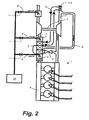
- reference number 1 refers to a piston engine connected to a turbocharger 2 in a way known as such.
- a fuel injector nozzle is arranged in connection with each cylinder for introducing fuel into the engine.
- a nozzle arrangement 4 for introducing water into the combustion air is arranged into the air channel 3 connecting the turbocharger 2 and the air channel 3, by means of which air is fed to the engine..
- a corresponding nozzle arrangement 4' is also arranged prior to the compressor of the turbocharger.
- the nozzle arrangement 4, 4' is connected to the water system, shown in the figures with reference number 10.
- it will also comprise a water source and it can also comprise a water pre-heater apparatus, the heat source of which preferably is the heat generated in the engine.
- a heat exchanger arrangement 5 is also arranged in the air channel 3 for increasing the temperature of the combustion air.
- the channel can comprise other heat exchangers as wen.
- the channel 3 is connected to the air chamber 8 of the engine 1, wherefrom air is Introduced into each cylinder of the engine via channel 3.
- the figures also show a droplet separator 6 used In the arrangement, if necessary.
- the nozzle arrangement 4, 4' is used for increasing the water content of the combustion air prior to introducing combustion air to the combustion chamber of the engine.
- the amount of water introduced into the air is preferably selected so that the air is essentially saturated. Typically the amount of water introduced with the combustion air is about 0.5 to 5 times the amount of fuel. According to the invention water is introduced into the air channel 3 as a liquid.
- the vaporisation of water in the air channel 3 uses the heat of air, and to avoid the temperature of the air failing too low and for simultaneously being able to vaporise a sufficient amount of water into the air, heat is introduced into the engine combustion air flowing in the air channel by means of a heat exchanger arrangement 5.
- a branch channel 9 through which the partial flow of the exhaust gas flow is directed to flow via the heat exchanger arrangement 5.
- a part of the heat energy of the exhaust gas coming from the engine combustion chamber can be transferred to the combustion air and thus such a combustion air temperature can be maintained that a sufficient amount of water can be vaporised therein and that a sufficient amount of water stays in vapour phase.
- the energy of the exhaust gases is used for vapourizing the water in combustion air.
- the branch channel 9 is thus in connection with the heat transfer apparatus 5, through which hot exhaust gas is arranged to flow.
- the branch channel is arranged to join back to the exhaust gas channel 7 subsequent to the turbine part of the compressor apparatus, and it is provided with a valve apparatus 11 for controlling the volume of the partial flow.
- the flow flowing through the branch channel 9 is initiated by the pressure difference caused by the turbine part of the compressor apparatus 2, and the volume of the flow can be adjusted by means of controlling the position of the valve apparatus 11.
- the control is carried out on basis of the current load of the engine and also on the comparison between the measurement value and the set value of the combustion air temperature.
- the arrangement comprises both a heat exchanger 5 in the exhaust gas channel for directly transferring heat from the exhaust gas and a second heat exchanger 5, connected to the separate heat transfer medium circuit 5' further comprising a second heat exchanger 5.1 arranged in the exhaust gas channel.
- the amount of water introduced into the combustion air is adjusted on the basis of the load of the engine, of which the pressure of the combustion air, for example, could be a suitable indicator.
- the amount of water introduced into the combustion air is adjusted by opening and closing a suitable amount of water injection nozzles as necessary, while the injection pressure at each nozzle is about constant.
- both a preferable atomising or misting of the water and a correct amount of water in the combustion air are achieved.
Landscapes
- Engineering & Computer Science (AREA)
- Chemical & Material Sciences (AREA)
- Combustion & Propulsion (AREA)
- Mechanical Engineering (AREA)
- General Engineering & Computer Science (AREA)
- Supercharger (AREA)
- Agricultural Chemicals And Associated Chemicals (AREA)
- Breeding Of Plants And Reproduction By Means Of Culturing (AREA)
Applications Claiming Priority (2)
| Application Number | Priority Date | Filing Date | Title |
|---|---|---|---|
| FI20031513A FI119119B (fi) | 2003-10-15 | 2003-10-15 | Menetelmä ahdetun mäntämoottorin typpioksidipäästöjen (NOx) vähentämiseksi ja mäntämoottorijärjestely |
| PCT/FI2004/050143 WO2005038229A1 (en) | 2003-10-15 | 2004-10-07 | A method of reducing the nitrogen oxide emissions (nox) of a supercharged piston engine and a piston engine arrangement |
Publications (2)
| Publication Number | Publication Date |
|---|---|
| EP1680590A1 EP1680590A1 (en) | 2006-07-19 |
| EP1680590B1 true EP1680590B1 (en) | 2009-07-15 |
Family
ID=29225957
Family Applications (1)
| Application Number | Title | Priority Date | Filing Date |
|---|---|---|---|
| EP04791435A Active EP1680590B1 (en) | 2003-10-15 | 2004-10-07 | A method of reducing the nitrogen oxide emissions (nox) of a supercharged piston engine and a piston engine arrangement |
Country Status (6)
| Country | Link |
|---|---|
| EP (1) | EP1680590B1 (fi) |
| KR (1) | KR101110924B1 (fi) |
| CN (1) | CN100408842C (fi) |
| DE (1) | DE602004022076D1 (fi) |
| FI (1) | FI119119B (fi) |
| WO (1) | WO2005038229A1 (fi) |
Families Citing this family (8)
| Publication number | Priority date | Publication date | Assignee | Title |
|---|---|---|---|---|
| FI116157B (fi) * | 2002-03-20 | 2005-09-30 | Waertsilae Finland Oy | Menetelmä ahdetun mäntämoottorin typpioksidipäästöjen (NOx) vähentämiseksi ja mäntämoottorijärjestely |
| FI119949B (fi) * | 2005-09-16 | 2009-05-15 | Waertsilae Finland Oy | Menetelmä turbokompressorilla varustetun mäntämoottorin yhteydessä |
| US8857162B2 (en) | 2012-11-02 | 2014-10-14 | Caterpillar Inc. | Coolant warm-up using exhaust |
| CN103147882A (zh) * | 2013-03-19 | 2013-06-12 | 龙口中宇热管理系统科技有限公司 | 水混合型废气再循环系统和利用该系统的发动机 |
| CN103195618A (zh) * | 2013-03-22 | 2013-07-10 | 上海交通大学 | 进排气管系热交换装置 |
| CN103195619A (zh) * | 2013-03-22 | 2013-07-10 | 上海交通大学 | 管路交叉式能量回收装置 |
| DE102014204509A1 (de) * | 2014-03-12 | 2015-09-17 | Bayerische Motoren Werke Aktiengesellschaft | Wassereinspritzanlage für einen Verbrennungsmotor |
| CN103867345A (zh) * | 2014-04-02 | 2014-06-18 | 中国船舶重工集团公司第七一一研究所 | 一种船用柴油机的进气加湿系统 |
Family Cites Families (8)
| Publication number | Priority date | Publication date | Assignee | Title |
|---|---|---|---|---|
| DE4225050C1 (de) * | 1992-07-29 | 1993-09-30 | Helmut Dallinga | Verfahren und Vorrichtung zur Durchführung des Verfahrens zum Klimatisieren der den Brennkammern von Brennkraftmaschinen zuzuführenden Frischluft |
| DE4231681A1 (de) * | 1992-07-29 | 1994-03-24 | Helmut Dallinga | Verfahren und Vorrichtung zur Durchführung des Verfahrens zum Klimatisieren der den Brennkammern von Brennkraftmaschinen zuzuführenden Frischluft bzw. des Frischluft-Kraftstoffgemisches durch direkten und/oder indirekten Austausch von Wärme und Feuchte |
| US5758505C1 (en) | 1995-10-12 | 2001-10-30 | Cryogen Inc | Precooling system for joule-thomson probe |
| DE19538067A1 (de) * | 1995-10-13 | 1997-04-17 | Erdgas En Systeme Gmbh | Stationäre Brennkraftmaschine und Verfahren zu ihrem Betreiben |
| DE19750181C2 (de) * | 1997-11-13 | 2000-06-21 | Munters Euroform Gmbh Carl | Vorrichtung zur Zuführung von Dampf zur Einlaßluft einer Brennkraftmaschine |
| DE19938292A1 (de) * | 1999-08-12 | 2001-02-15 | Munters Euroform Gmbh Carl | Vorrichtung zur Befeuchtung der Einlaßluft von Brennkraftmaschinen mit Turbolader |
| CN1294259A (zh) * | 1999-10-26 | 2001-05-09 | 史玉成 | 内燃机节能、降污排放装置 |
| FI116157B (fi) * | 2002-03-20 | 2005-09-30 | Waertsilae Finland Oy | Menetelmä ahdetun mäntämoottorin typpioksidipäästöjen (NOx) vähentämiseksi ja mäntämoottorijärjestely |
-
2003
- 2003-10-15 FI FI20031513A patent/FI119119B/fi not_active IP Right Cessation
-
2004
- 2004-10-07 CN CNB200480029792XA patent/CN100408842C/zh not_active Expired - Fee Related
- 2004-10-07 KR KR1020067005463A patent/KR101110924B1/ko active IP Right Grant
- 2004-10-07 EP EP04791435A patent/EP1680590B1/en active Active
- 2004-10-07 WO PCT/FI2004/050143 patent/WO2005038229A1/en active Search and Examination
- 2004-10-07 DE DE602004022076T patent/DE602004022076D1/de active Active
Also Published As
| Publication number | Publication date |
|---|---|
| EP1680590A1 (en) | 2006-07-19 |
| FI20031513A0 (fi) | 2003-10-15 |
| FI119119B (fi) | 2008-07-31 |
| WO2005038229A1 (en) | 2005-04-28 |
| DE602004022076D1 (de) | 2009-08-27 |
| CN100408842C (zh) | 2008-08-06 |
| CN1902394A (zh) | 2007-01-24 |
| KR20070004519A (ko) | 2007-01-09 |
| KR101110924B1 (ko) | 2012-04-12 |
| FI20031513A (fi) | 2005-04-16 |
Similar Documents
| Publication | Publication Date | Title |
|---|---|---|
| US4949544A (en) | Series intercooler | |
| US7481060B2 (en) | Method for operating a power plant | |
| CN107893715B (zh) | 内燃发动机的进气排气系统 | |
| RU2136941C1 (ru) | Способ для подачи пара во всасываемый воздух в двигателе внутреннего сгорания и устройство для его осуществления | |
| US7225762B2 (en) | Spraying method and apparatus | |
| EP1205659B1 (en) | Method of reducing nitrogen oxide (NOX) emissions of super-charged piston engine | |
| JP2008281008A (ja) | ディーゼル機関に接続する装置及び接続方法 | |
| FI116157B (fi) | Menetelmä ahdetun mäntämoottorin typpioksidipäästöjen (NOx) vähentämiseksi ja mäntämoottorijärjestely | |
| US20110179793A1 (en) | Method for operating an internal combustion engine having a steam power plant | |
| EP1680590B1 (en) | A method of reducing the nitrogen oxide emissions (nox) of a supercharged piston engine and a piston engine arrangement | |
| US6817348B2 (en) | Device for humidifying the intake air of an internal combustion engine, which is equipped with a turbocharger, involving pre-heating effected by a water circuit | |
| EP1234105B1 (en) | Sequential use of steam | |
| CA2433636C (en) | Installation for the generation of energy | |
| KR100545450B1 (ko) | 내연기관용 과급공기 가습 장치 |
Legal Events
| Date | Code | Title | Description |
|---|---|---|---|
| PUAI | Public reference made under article 153(3) epc to a published international application that has entered the european phase |
Free format text: ORIGINAL CODE: 0009012 |
|
| 17P | Request for examination filed |
Effective date: 20060320 |
|
| AK | Designated contracting states |
Kind code of ref document: A1 Designated state(s): AT BE BG CH CY CZ DE DK EE ES FI FR GB GR HU IE IT LI LU MC NL PL PT RO SE SI SK TR |
|
| DAX | Request for extension of the european patent (deleted) | ||
| 17Q | First examination report despatched |
Effective date: 20080902 |
|
| GRAP | Despatch of communication of intention to grant a patent |
Free format text: ORIGINAL CODE: EPIDOSNIGR1 |
|
| GRAS | Grant fee paid |
Free format text: ORIGINAL CODE: EPIDOSNIGR3 |
|
| GRAA | (expected) grant |
Free format text: ORIGINAL CODE: 0009210 |
|
| AK | Designated contracting states |
Kind code of ref document: B1 Designated state(s): AT BE BG CH CY CZ DE DK EE ES FI FR GB GR HU IE IT LI LU MC NL PL PT RO SE SI SK TR |
|
| REG | Reference to a national code |
Ref country code: CH Ref legal event code: EP Ref country code: GB Ref legal event code: FG4D |
|
| REG | Reference to a national code |
Ref country code: IE Ref legal event code: FG4D |
|
| REF | Corresponds to: |
Ref document number: 602004022076 Country of ref document: DE Date of ref document: 20090827 Kind code of ref document: P |
|
| NLV1 | Nl: lapsed or annulled due to failure to fulfill the requirements of art. 29p and 29m of the patents act | ||
| PG25 | Lapsed in a contracting state [announced via postgrant information from national office to epo] |
Ref country code: SE Free format text: LAPSE BECAUSE OF FAILURE TO SUBMIT A TRANSLATION OF THE DESCRIPTION OR TO PAY THE FEE WITHIN THE PRESCRIBED TIME-LIMIT Effective date: 20090715 Ref country code: FI Free format text: LAPSE BECAUSE OF FAILURE TO SUBMIT A TRANSLATION OF THE DESCRIPTION OR TO PAY THE FEE WITHIN THE PRESCRIBED TIME-LIMIT Effective date: 20090715 Ref country code: AT Free format text: LAPSE BECAUSE OF FAILURE TO SUBMIT A TRANSLATION OF THE DESCRIPTION OR TO PAY THE FEE WITHIN THE PRESCRIBED TIME-LIMIT Effective date: 20090715 Ref country code: ES Free format text: LAPSE BECAUSE OF FAILURE TO SUBMIT A TRANSLATION OF THE DESCRIPTION OR TO PAY THE FEE WITHIN THE PRESCRIBED TIME-LIMIT Effective date: 20091026 |
|
| PG25 | Lapsed in a contracting state [announced via postgrant information from national office to epo] |
Ref country code: PL Free format text: LAPSE BECAUSE OF FAILURE TO SUBMIT A TRANSLATION OF THE DESCRIPTION OR TO PAY THE FEE WITHIN THE PRESCRIBED TIME-LIMIT Effective date: 20090715 Ref country code: SI Free format text: LAPSE BECAUSE OF FAILURE TO SUBMIT A TRANSLATION OF THE DESCRIPTION OR TO PAY THE FEE WITHIN THE PRESCRIBED TIME-LIMIT Effective date: 20090715 Ref country code: NL Free format text: LAPSE BECAUSE OF FAILURE TO SUBMIT A TRANSLATION OF THE DESCRIPTION OR TO PAY THE FEE WITHIN THE PRESCRIBED TIME-LIMIT Effective date: 20090715 |
|
| PG25 | Lapsed in a contracting state [announced via postgrant information from national office to epo] |
Ref country code: PT Free format text: LAPSE BECAUSE OF FAILURE TO SUBMIT A TRANSLATION OF THE DESCRIPTION OR TO PAY THE FEE WITHIN THE PRESCRIBED TIME-LIMIT Effective date: 20091115 Ref country code: BG Free format text: LAPSE BECAUSE OF FAILURE TO SUBMIT A TRANSLATION OF THE DESCRIPTION OR TO PAY THE FEE WITHIN THE PRESCRIBED TIME-LIMIT Effective date: 20091015 |
|
| PG25 | Lapsed in a contracting state [announced via postgrant information from national office to epo] |
Ref country code: DK Free format text: LAPSE BECAUSE OF FAILURE TO SUBMIT A TRANSLATION OF THE DESCRIPTION OR TO PAY THE FEE WITHIN THE PRESCRIBED TIME-LIMIT Effective date: 20090715 Ref country code: CZ Free format text: LAPSE BECAUSE OF FAILURE TO SUBMIT A TRANSLATION OF THE DESCRIPTION OR TO PAY THE FEE WITHIN THE PRESCRIBED TIME-LIMIT Effective date: 20090715 Ref country code: RO Free format text: LAPSE BECAUSE OF FAILURE TO SUBMIT A TRANSLATION OF THE DESCRIPTION OR TO PAY THE FEE WITHIN THE PRESCRIBED TIME-LIMIT Effective date: 20090715 Ref country code: EE Free format text: LAPSE BECAUSE OF FAILURE TO SUBMIT A TRANSLATION OF THE DESCRIPTION OR TO PAY THE FEE WITHIN THE PRESCRIBED TIME-LIMIT Effective date: 20090715 |
|
| PLBE | No opposition filed within time limit |
Free format text: ORIGINAL CODE: 0009261 |
|
| STAA | Information on the status of an ep patent application or granted ep patent |
Free format text: STATUS: NO OPPOSITION FILED WITHIN TIME LIMIT |
|
| PG25 | Lapsed in a contracting state [announced via postgrant information from national office to epo] |
Ref country code: SK Free format text: LAPSE BECAUSE OF FAILURE TO SUBMIT A TRANSLATION OF THE DESCRIPTION OR TO PAY THE FEE WITHIN THE PRESCRIBED TIME-LIMIT Effective date: 20090715 Ref country code: MC Free format text: LAPSE BECAUSE OF NON-PAYMENT OF DUE FEES Effective date: 20091031 Ref country code: BE Free format text: LAPSE BECAUSE OF FAILURE TO SUBMIT A TRANSLATION OF THE DESCRIPTION OR TO PAY THE FEE WITHIN THE PRESCRIBED TIME-LIMIT Effective date: 20090715 |
|
| 26N | No opposition filed |
Effective date: 20100416 |
|
| REG | Reference to a national code |
Ref country code: FR Ref legal event code: ST Effective date: 20100630 |
|
| PG25 | Lapsed in a contracting state [announced via postgrant information from national office to epo] |
Ref country code: FR Free format text: LAPSE BECAUSE OF NON-PAYMENT OF DUE FEES Effective date: 20091102 |
|
| PG25 | Lapsed in a contracting state [announced via postgrant information from national office to epo] |
Ref country code: GR Free format text: LAPSE BECAUSE OF FAILURE TO SUBMIT A TRANSLATION OF THE DESCRIPTION OR TO PAY THE FEE WITHIN THE PRESCRIBED TIME-LIMIT Effective date: 20091016 Ref country code: IE Free format text: LAPSE BECAUSE OF NON-PAYMENT OF DUE FEES Effective date: 20091007 |
|
| PG25 | Lapsed in a contracting state [announced via postgrant information from national office to epo] |
Ref country code: LU Free format text: LAPSE BECAUSE OF NON-PAYMENT OF DUE FEES Effective date: 20091007 |
|
| PG25 | Lapsed in a contracting state [announced via postgrant information from national office to epo] |
Ref country code: HU Free format text: LAPSE BECAUSE OF FAILURE TO SUBMIT A TRANSLATION OF THE DESCRIPTION OR TO PAY THE FEE WITHIN THE PRESCRIBED TIME-LIMIT Effective date: 20100116 |
|
| PG25 | Lapsed in a contracting state [announced via postgrant information from national office to epo] |
Ref country code: TR Free format text: LAPSE BECAUSE OF FAILURE TO SUBMIT A TRANSLATION OF THE DESCRIPTION OR TO PAY THE FEE WITHIN THE PRESCRIBED TIME-LIMIT Effective date: 20090715 |
|
| PG25 | Lapsed in a contracting state [announced via postgrant information from national office to epo] |
Ref country code: CY Free format text: LAPSE BECAUSE OF FAILURE TO SUBMIT A TRANSLATION OF THE DESCRIPTION OR TO PAY THE FEE WITHIN THE PRESCRIBED TIME-LIMIT Effective date: 20090715 |
|
| PGFP | Annual fee paid to national office [announced via postgrant information from national office to epo] |
Ref country code: IT Payment date: 20171019 Year of fee payment: 14 Ref country code: CH Payment date: 20171019 Year of fee payment: 14 |
|
| REG | Reference to a national code |
Ref country code: CH Ref legal event code: PL |
|
| PG25 | Lapsed in a contracting state [announced via postgrant information from national office to epo] |
Ref country code: CH Free format text: LAPSE BECAUSE OF NON-PAYMENT OF DUE FEES Effective date: 20181031 Ref country code: LI Free format text: LAPSE BECAUSE OF NON-PAYMENT OF DUE FEES Effective date: 20181031 |
|
| PG25 | Lapsed in a contracting state [announced via postgrant information from national office to epo] |
Ref country code: IT Free format text: LAPSE BECAUSE OF NON-PAYMENT OF DUE FEES Effective date: 20181007 |
|
| PGFP | Annual fee paid to national office [announced via postgrant information from national office to epo] |
Ref country code: GB Payment date: 20191021 Year of fee payment: 16 |
|
| GBPC | Gb: european patent ceased through non-payment of renewal fee |
Effective date: 20201007 |
|
| PG25 | Lapsed in a contracting state [announced via postgrant information from national office to epo] |
Ref country code: GB Free format text: LAPSE BECAUSE OF NON-PAYMENT OF DUE FEES Effective date: 20201007 |
|
| PGFP | Annual fee paid to national office [announced via postgrant information from national office to epo] |
Ref country code: DE Payment date: 20221019 Year of fee payment: 19 |