EP1680585B1 - Systeme d aide a la regeneration de moyens de depollution in tegres dans une ligne d echappement d un moteur diesel de vehicule - Google Patents
Systeme d aide a la regeneration de moyens de depollution in tegres dans une ligne d echappement d un moteur diesel de vehicule Download PDFInfo
- Publication number
- EP1680585B1 EP1680585B1 EP04791463A EP04791463A EP1680585B1 EP 1680585 B1 EP1680585 B1 EP 1680585B1 EP 04791463 A EP04791463 A EP 04791463A EP 04791463 A EP04791463 A EP 04791463A EP 1680585 B1 EP1680585 B1 EP 1680585B1
- Authority
- EP
- European Patent Office
- Prior art keywords
- post
- injection
- engine
- regeneration
- fuel
- Prior art date
- Legal status (The legal status is an assumption and is not a legal conclusion. Google has not performed a legal analysis and makes no representation as to the accuracy of the status listed.)
- Active
Links
- 230000008929 regeneration Effects 0.000 title claims abstract description 25
- 238000011069 regeneration method Methods 0.000 title claims abstract description 25
- 238000002347 injection Methods 0.000 claims abstract description 46
- 239000007924 injection Substances 0.000 claims abstract description 46
- 239000000446 fuel Substances 0.000 claims abstract description 34
- 239000003054 catalyst Substances 0.000 claims abstract description 20
- 230000003647 oxidation Effects 0.000 claims abstract description 13
- 238000007254 oxidation reaction Methods 0.000 claims abstract description 13
- 239000000654 additive Substances 0.000 claims abstract description 11
- 230000000996 additive effect Effects 0.000 claims abstract description 11
- 230000000994 depressogenic effect Effects 0.000 claims 2
- 230000008021 deposition Effects 0.000 claims 1
- 239000002245 particle Substances 0.000 abstract description 5
- 230000000750 progressive effect Effects 0.000 abstract description 3
- 238000006243 chemical reaction Methods 0.000 description 5
- 238000002485 combustion reaction Methods 0.000 description 5
- 230000003197 catalytic effect Effects 0.000 description 4
- 238000010790 dilution Methods 0.000 description 2
- 239000012895 dilution Substances 0.000 description 2
- 239000003517 fume Substances 0.000 description 2
- 239000010687 lubricating oil Substances 0.000 description 2
- 235000019645 odor Nutrition 0.000 description 2
- 230000006735 deficit Effects 0.000 description 1
- 238000001514 detection method Methods 0.000 description 1
- 238000010586 diagram Methods 0.000 description 1
- 230000000694 effects Effects 0.000 description 1
- 239000002816 fuel additive Substances 0.000 description 1
- 230000001050 lubricating effect Effects 0.000 description 1
- 230000000630 rising effect Effects 0.000 description 1
- 239000004071 soot Substances 0.000 description 1
- 239000000758 substrate Substances 0.000 description 1
- 238000011144 upstream manufacturing Methods 0.000 description 1
Images
Classifications
-
- F—MECHANICAL ENGINEERING; LIGHTING; HEATING; WEAPONS; BLASTING
- F01—MACHINES OR ENGINES IN GENERAL; ENGINE PLANTS IN GENERAL; STEAM ENGINES
- F01N—GAS-FLOW SILENCERS OR EXHAUST APPARATUS FOR MACHINES OR ENGINES IN GENERAL; GAS-FLOW SILENCERS OR EXHAUST APPARATUS FOR INTERNAL COMBUSTION ENGINES
- F01N11/00—Monitoring or diagnostic devices for exhaust-gas treatment apparatus, e.g. for catalytic activity
- F01N11/002—Monitoring or diagnostic devices for exhaust-gas treatment apparatus, e.g. for catalytic activity the diagnostic devices measuring or estimating temperature or pressure in, or downstream of the exhaust apparatus
-
- F—MECHANICAL ENGINEERING; LIGHTING; HEATING; WEAPONS; BLASTING
- F01—MACHINES OR ENGINES IN GENERAL; ENGINE PLANTS IN GENERAL; STEAM ENGINES
- F01N—GAS-FLOW SILENCERS OR EXHAUST APPARATUS FOR MACHINES OR ENGINES IN GENERAL; GAS-FLOW SILENCERS OR EXHAUST APPARATUS FOR INTERNAL COMBUSTION ENGINES
- F01N13/00—Exhaust or silencing apparatus characterised by constructional features ; Exhaust or silencing apparatus, or parts thereof, having pertinent characteristics not provided for in, or of interest apart from, groups F01N1/00 - F01N5/00, F01N9/00, F01N11/00
- F01N13/009—Exhaust or silencing apparatus characterised by constructional features ; Exhaust or silencing apparatus, or parts thereof, having pertinent characteristics not provided for in, or of interest apart from, groups F01N1/00 - F01N5/00, F01N9/00, F01N11/00 having two or more separate purifying devices arranged in series
-
- F—MECHANICAL ENGINEERING; LIGHTING; HEATING; WEAPONS; BLASTING
- F01—MACHINES OR ENGINES IN GENERAL; ENGINE PLANTS IN GENERAL; STEAM ENGINES
- F01N—GAS-FLOW SILENCERS OR EXHAUST APPARATUS FOR MACHINES OR ENGINES IN GENERAL; GAS-FLOW SILENCERS OR EXHAUST APPARATUS FOR INTERNAL COMBUSTION ENGINES
- F01N3/00—Exhaust or silencing apparatus having means for purifying, rendering innocuous, or otherwise treating exhaust
- F01N3/02—Exhaust or silencing apparatus having means for purifying, rendering innocuous, or otherwise treating exhaust for cooling, or for removing solid constituents of, exhaust
- F01N3/021—Exhaust or silencing apparatus having means for purifying, rendering innocuous, or otherwise treating exhaust for cooling, or for removing solid constituents of, exhaust by means of filters
- F01N3/033—Exhaust or silencing apparatus having means for purifying, rendering innocuous, or otherwise treating exhaust for cooling, or for removing solid constituents of, exhaust by means of filters in combination with other devices
- F01N3/035—Exhaust or silencing apparatus having means for purifying, rendering innocuous, or otherwise treating exhaust for cooling, or for removing solid constituents of, exhaust by means of filters in combination with other devices with catalytic reactors, e.g. catalysed diesel particulate filters
-
- F—MECHANICAL ENGINEERING; LIGHTING; HEATING; WEAPONS; BLASTING
- F01—MACHINES OR ENGINES IN GENERAL; ENGINE PLANTS IN GENERAL; STEAM ENGINES
- F01N—GAS-FLOW SILENCERS OR EXHAUST APPARATUS FOR MACHINES OR ENGINES IN GENERAL; GAS-FLOW SILENCERS OR EXHAUST APPARATUS FOR INTERNAL COMBUSTION ENGINES
- F01N3/00—Exhaust or silencing apparatus having means for purifying, rendering innocuous, or otherwise treating exhaust
- F01N3/08—Exhaust or silencing apparatus having means for purifying, rendering innocuous, or otherwise treating exhaust for rendering innocuous
- F01N3/0807—Exhaust or silencing apparatus having means for purifying, rendering innocuous, or otherwise treating exhaust for rendering innocuous by using absorbents or adsorbents
- F01N3/0814—Exhaust or silencing apparatus having means for purifying, rendering innocuous, or otherwise treating exhaust for rendering innocuous by using absorbents or adsorbents combined with catalytic converters, e.g. NOx absorption/storage reduction catalysts
-
- F—MECHANICAL ENGINEERING; LIGHTING; HEATING; WEAPONS; BLASTING
- F01—MACHINES OR ENGINES IN GENERAL; ENGINE PLANTS IN GENERAL; STEAM ENGINES
- F01N—GAS-FLOW SILENCERS OR EXHAUST APPARATUS FOR MACHINES OR ENGINES IN GENERAL; GAS-FLOW SILENCERS OR EXHAUST APPARATUS FOR INTERNAL COMBUSTION ENGINES
- F01N3/00—Exhaust or silencing apparatus having means for purifying, rendering innocuous, or otherwise treating exhaust
- F01N3/08—Exhaust or silencing apparatus having means for purifying, rendering innocuous, or otherwise treating exhaust for rendering innocuous
- F01N3/0807—Exhaust or silencing apparatus having means for purifying, rendering innocuous, or otherwise treating exhaust for rendering innocuous by using absorbents or adsorbents
- F01N3/0828—Exhaust or silencing apparatus having means for purifying, rendering innocuous, or otherwise treating exhaust for rendering innocuous by using absorbents or adsorbents characterised by the absorbed or adsorbed substances
- F01N3/0842—Nitrogen oxides
-
- F—MECHANICAL ENGINEERING; LIGHTING; HEATING; WEAPONS; BLASTING
- F02—COMBUSTION ENGINES; HOT-GAS OR COMBUSTION-PRODUCT ENGINE PLANTS
- F02D—CONTROLLING COMBUSTION ENGINES
- F02D41/00—Electrical control of supply of combustible mixture or its constituents
- F02D41/02—Circuit arrangements for generating control signals
- F02D41/021—Introducing corrections for particular conditions exterior to the engine
- F02D41/0235—Introducing corrections for particular conditions exterior to the engine in relation with the state of the exhaust gas treating apparatus
- F02D41/024—Introducing corrections for particular conditions exterior to the engine in relation with the state of the exhaust gas treating apparatus to increase temperature of the exhaust gas treating apparatus
- F02D41/025—Introducing corrections for particular conditions exterior to the engine in relation with the state of the exhaust gas treating apparatus to increase temperature of the exhaust gas treating apparatus by changing the composition of the exhaust gas, e.g. for exothermic reaction on exhaust gas treating apparatus
-
- F—MECHANICAL ENGINEERING; LIGHTING; HEATING; WEAPONS; BLASTING
- F02—COMBUSTION ENGINES; HOT-GAS OR COMBUSTION-PRODUCT ENGINE PLANTS
- F02D—CONTROLLING COMBUSTION ENGINES
- F02D41/00—Electrical control of supply of combustible mixture or its constituents
- F02D41/30—Controlling fuel injection
- F02D41/38—Controlling fuel injection of the high pressure type
- F02D41/40—Controlling fuel injection of the high pressure type with means for controlling injection timing or duration
- F02D41/402—Multiple injections
- F02D41/405—Multiple injections with post injections
-
- F—MECHANICAL ENGINEERING; LIGHTING; HEATING; WEAPONS; BLASTING
- F01—MACHINES OR ENGINES IN GENERAL; ENGINE PLANTS IN GENERAL; STEAM ENGINES
- F01N—GAS-FLOW SILENCERS OR EXHAUST APPARATUS FOR MACHINES OR ENGINES IN GENERAL; GAS-FLOW SILENCERS OR EXHAUST APPARATUS FOR INTERNAL COMBUSTION ENGINES
- F01N2560/00—Exhaust systems with means for detecting or measuring exhaust gas components or characteristics
- F01N2560/06—Exhaust systems with means for detecting or measuring exhaust gas components or characteristics the means being a temperature sensor
-
- F—MECHANICAL ENGINEERING; LIGHTING; HEATING; WEAPONS; BLASTING
- F02—COMBUSTION ENGINES; HOT-GAS OR COMBUSTION-PRODUCT ENGINE PLANTS
- F02B—INTERNAL-COMBUSTION PISTON ENGINES; COMBUSTION ENGINES IN GENERAL
- F02B37/00—Engines characterised by provision of pumps driven at least for part of the time by exhaust
-
- F—MECHANICAL ENGINEERING; LIGHTING; HEATING; WEAPONS; BLASTING
- F02—COMBUSTION ENGINES; HOT-GAS OR COMBUSTION-PRODUCT ENGINE PLANTS
- F02D—CONTROLLING COMBUSTION ENGINES
- F02D2200/00—Input parameters for engine control
- F02D2200/02—Input parameters for engine control the parameters being related to the engine
- F02D2200/08—Exhaust gas treatment apparatus parameters
- F02D2200/0802—Temperature of the exhaust gas treatment apparatus
-
- F—MECHANICAL ENGINEERING; LIGHTING; HEATING; WEAPONS; BLASTING
- F02—COMBUSTION ENGINES; HOT-GAS OR COMBUSTION-PRODUCT ENGINE PLANTS
- F02D—CONTROLLING COMBUSTION ENGINES
- F02D2250/00—Engine control related to specific problems or objectives
- F02D2250/11—Oil dilution, i.e. prevention thereof or special controls according thereto
-
- F—MECHANICAL ENGINEERING; LIGHTING; HEATING; WEAPONS; BLASTING
- F02—COMBUSTION ENGINES; HOT-GAS OR COMBUSTION-PRODUCT ENGINE PLANTS
- F02D—CONTROLLING COMBUSTION ENGINES
- F02D41/00—Electrical control of supply of combustible mixture or its constituents
- F02D41/02—Circuit arrangements for generating control signals
- F02D41/021—Introducing corrections for particular conditions exterior to the engine
- F02D41/0235—Introducing corrections for particular conditions exterior to the engine in relation with the state of the exhaust gas treating apparatus
- F02D41/027—Introducing corrections for particular conditions exterior to the engine in relation with the state of the exhaust gas treating apparatus to purge or regenerate the exhaust gas treating apparatus
- F02D41/029—Introducing corrections for particular conditions exterior to the engine in relation with the state of the exhaust gas treating apparatus to purge or regenerate the exhaust gas treating apparatus the exhaust gas treating apparatus being a particulate filter
-
- Y—GENERAL TAGGING OF NEW TECHNOLOGICAL DEVELOPMENTS; GENERAL TAGGING OF CROSS-SECTIONAL TECHNOLOGIES SPANNING OVER SEVERAL SECTIONS OF THE IPC; TECHNICAL SUBJECTS COVERED BY FORMER USPC CROSS-REFERENCE ART COLLECTIONS [XRACs] AND DIGESTS
- Y02—TECHNOLOGIES OR APPLICATIONS FOR MITIGATION OR ADAPTATION AGAINST CLIMATE CHANGE
- Y02T—CLIMATE CHANGE MITIGATION TECHNOLOGIES RELATED TO TRANSPORTATION
- Y02T10/00—Road transport of goods or passengers
- Y02T10/10—Internal combustion engine [ICE] based vehicles
- Y02T10/12—Improving ICE efficiencies
-
- Y—GENERAL TAGGING OF NEW TECHNOLOGICAL DEVELOPMENTS; GENERAL TAGGING OF CROSS-SECTIONAL TECHNOLOGIES SPANNING OVER SEVERAL SECTIONS OF THE IPC; TECHNICAL SUBJECTS COVERED BY FORMER USPC CROSS-REFERENCE ART COLLECTIONS [XRACs] AND DIGESTS
- Y02—TECHNOLOGIES OR APPLICATIONS FOR MITIGATION OR ADAPTATION AGAINST CLIMATE CHANGE
- Y02T—CLIMATE CHANGE MITIGATION TECHNOLOGIES RELATED TO TRANSPORTATION
- Y02T10/00—Road transport of goods or passengers
- Y02T10/10—Internal combustion engine [ICE] based vehicles
- Y02T10/40—Engine management systems
Definitions
- the present invention relates to a system for assisting the regeneration of depollution means associated with oxidation catalyst means, and integrated in an exhaust line of a motor vehicle diesel engine.
- the invention relates to a system in which the engine is associated with means with common rail for supplying fuel to engine cylinders, adapted to implement, at iso-torque, an injection regeneration strategy. of fuel in the cylinders, according to at least one post-injection, see for example DE 19957185 and DE 19851811 .
- depollution means such as for example a particulate filter
- the lift phases of the accelerator of the vehicle no fuel injection during normal operation
- engine idling engine temperature
- exhaust very low are problematic because they drop the exhaust temperature, that is to say, the line and integrated elements in it.
- the use of one or more post-injections during these phases of the engine life limits the temperature drop of the exhaust line, based on the catalytic conversion of the HC produced by the combustion of the or post-injections into the motor.
- these strategies are based on the exotherm produced by the catalyst means, these means, comprising for example an oxidation catalyst or a NOx trap with a CO / HC oxidation function, being considered as activated.
- the inlet temperature of the oxidation catalyst means is therefore very low and despite the catalytic exotherm produced by the combustion of the HCs resulting from the or each post-injection, the front face of the catalyst means progressively cools and its conversion gradually defuses.
- the inlet temperature of the catalyst-forming means is relatively low.
- the idle post-injection strategy is also based on the catalytic conversion of the HC produced by the combustion of the post-injection (s) in the engine. Despite this catalytic exotherm, the front face of the catalyst means progressively cools and its conversion activity gradually defuses.
- the catalyst means may not be sufficiently active to convert all HCs, resulting in downstream HC peaks. these catalyst means, or even blue fumes and / or exhaust odors.
- the use of post-injections causes a dilution of the lubricating oil by the fuel, which degrades the lubricating properties thereof, and in particular a decrease in viscosity and can lead if this viscosity is too much. low, to a breakage of the engine.
- the object of the invention is therefore to solve these problems.
- the engine can be associated with a turbocharger and in this case, the turbine portion 5 thereof is also associated with this exhaust line, the portion of the compressor 6 of the turbocharger being placed upstream of the engine.
- this engine is also associated with common rail fuel supply means 7 for the cylinders of this engine, adapted to implement, at iso-torque, a regeneration strategy by injecting fuel into the cylinders, according to at least one post-injection, in a conventional manner.
- control unit designated by the general reference 8 adapted to detect a req.RG regeneration request, issued for example by a supervisor of the depollution means, and therefore post-injection and connected to means 9 for detecting a state of lifting of the accelerator of the vehicle and means for detecting an idle phase of the engine thereof, designated by the general reference 10.
- this control unit 8 is also connected to means for acquiring the temperature downstream of the catalyst forming means 2, these acquisition means being designated by the general reference 11.
- These means include any suitable temperature sensor.
- this control unit 8 makes it possible, following the detection of a request for regeneration and therefore of post-injection, to this control unit 8, to detect a lever state of the accelerator of the vehicle or an idle phase of the engine. this one, as illustrated by step 12 on the figure 2 .
- the unit 8 is then adapted to acquire the temperature downstream of the catalyst means during step 13 and to determine a maximum quantity of fuel to be injected during the post-injections during the phases of idling, following a rising accelerator foot or idle, from this temperature, in step 14.
- the unit 8 then monitors at 15 and 16, the quantity of fuel injected during the post-injections, and detects the moment when this quantity of fuel injected has reached the predetermined maximum quantity.
- control unit 8 is adapted to cut immediately. the or each post-injection, as illustrated by step 18.
- control unit is adapted to progressively reduce the or each post-injection. , according to a ramp for example calibrated at 20.
- such a system can operate with pollution control means formed by a particulate filter, a NOx trap, and an additive intended to be deposited with the particles to which it is mixed, on the means of depollution for facilitate their regeneration can also be mixed with the fuel, in a conventional manner, to lower the combustion temperature of the soot trapped therein.
- pollution control means formed by a particulate filter, a NOx trap, and an additive intended to be deposited with the particles to which it is mixed, on the means of depollution for facilitate their regeneration can also be mixed with the fuel, in a conventional manner, to lower the combustion temperature of the soot trapped therein.
- this additive is indeed present in the particles after combustion of the fuel additive in the engine.
- An additive forming a NOx trap can also be envisaged.
- This maximum amount is in the form of a reservoir that empties as one accumulates the idling and / or footing phases during the regeneration phase. This tank is reset at the end of the phases.
- this system makes it possible to limit the post-injected quantities during the phases of lifting of foot or idle when the thermal levels of the exhaust line are the most unfavorable.
- the proportion of effective post-injection time is optimized and the dilution of the engine lubricating oil by the fuel.
- the depollution means and the oxidation catalyst means may be integrated into one and the same element, in particular on the same substrate.
- a particulate filter incorporating the oxidation function can be envisaged.
- NOx trap incorporating such an oxidation function can also be envisaged, whether or not it is additive.
- This oxidation function and / or NOx trap can be filled for example by an additive mixed with the fuel.
Landscapes
- Engineering & Computer Science (AREA)
- Chemical & Material Sciences (AREA)
- Combustion & Propulsion (AREA)
- Mechanical Engineering (AREA)
- General Engineering & Computer Science (AREA)
- Chemical Kinetics & Catalysis (AREA)
- Electrical Control Of Air Or Fuel Supplied To Internal-Combustion Engine (AREA)
- Exhaust Gas After Treatment (AREA)
- Processes For Solid Components From Exhaust (AREA)
Description
- La présente invention concerne un système d'aide à la régénération de moyens de dépollution associés à des moyens formant catalyseur d'oxydation, et intégrés dans une ligne d'échappement d'un moteur Diesel de véhicule automobile.
- Plus particulièrement, l'invention se rapporte à un système dans lequel le moteur est associé à des moyens à rampe commune d'alimentation en carburant de cylindres du moteur, adaptés pour mettre en oeuvre, à iso-couple, une stratégie de régénération par injection de carburant dans les cylindres, selon au moins une post-injection, voir par exemple
DE 19957185 etDE 19851811 . - Lors de la régénération de moyens de dépollution tels que par exemple un filtre à particules, les phases de lever de pied de l'accélérateur du véhicule (pas d'injection de carburant en fonctionnement normal), et de ralenti du moteur (température d'échappement très faible), sont problématique car elles font chuter la température d'échappement, c'est-à-dire de la ligne et des éléments intégrés dans celle-ci.
- L'utilisation d'une ou de plusieurs post-injections lors de ces phases de vie du moteur permet de limiter la chute de température de la ligne d'échappement, en se basant sur la conversion catalytique des HC produits par la combustion de la ou des post-injections dans le moteur.
- Cependant, ces stratégies reposent sur l'exotherme produit par les moyens formant catalyseur, ces moyens, comprenant par exemple un catalyseur d'oxydation ou un piège à NOx avec une fonction d'oxydation CO/HC, étant considérés comme activés.
- Lors des phases de retour au ralenti du moteur, consécutivement à un lever de pied de l'accélérateur, il n'y a pas d'injection principale ni d'injection pilote et la ou chaque post-injection ne brûle donc pas dans le cylindre, car elle ne fait que vaporiser le carburant sous forme d'HC qui sont convertis par les moyens formant catalyseur.
- La température en entrée des moyens formant catalyseur d'oxydation est donc très faible et malgré l'exotherme catalytique produit par la combustion des HC issus de la ou de chaque post-injection, la face avant des moyens formant catalyseur refroidit progressivement et son activité de conversion se désamorce progressivement.
- Lors des phases de ralenti du moteur, malgré l'utilisation d'une ou plusieurs post-injections, la température en entrée des moyens formant catalyseur est relativement faible. La stratégie de post-injection au ralenti repose également sur la conversion catalytique des HC produits par la combustion de la ou des post-injections dans le moteur. Malgré cet exotherme catalytique, la face avant des moyens formant catalyseur refroidit progressivement et son activité de conversion se désamorce progressivement.
- Lors d'une phase de retour au ralenti ou d'une phase de ralenti prolongée, il se peut que les moyens formant catalyseur ne soient donc pas suffisamment actifs pour convertir tous les HC, ce qui se traduit par des pics d'HC en aval de ces moyens formant catalyseur, voire des fumées bleues et/ou des odeurs à l'échappement.
- Par ailleurs, l'utilisation de post-injections engendre une dilution de l'huile de lubrification par le carburant, ce qui dégrade les propriétés de lubrification de celle-ci, et notamment une baisse de la viscosité et peut conduire si cette viscosité est trop basse, à une casse du moteur.
- Le but de l'invention est donc de résoudre ces problèmes.
- A cet effet, l'invention a pour objet un système d'aide à la régénération d'un filtre à particules associé à des moyens formant catalyseur d'oxydation, et intégrés dans une ligne d'échappement d'un moteur Diesel de véhicule automobile et dans lequel le moteur est associé à des moyens à rampe commune d'alimentation en carburant de cylindres du moteur, adaptés pour mettre en oeuvre, à iso-couple, une stratégie de régénération par injection de carburant dans les cylindres selon au moins une post-injection, caractérisé en ce qu'il comporte :
- des moyens de détection d'une requête de régénération et donc de post-injection ;
- des moyens de détection d'un état de lever de pied de l'accélérateur du véhicule et/ ou d'une phase de ralenti du moteur de celui-ci ;
- des moyens d'acquisition de la température en aval des moyens formant catalyseur ;
- des moyens de détermination d'une quantité totale de carburant à injecter lors des post-injections durant les phases de retour au ralenti consécutivement à un lever de pied de l'accélérateur et de ralenti, à partir de cette température ; et
- des moyens de coupure immédiate de la ou de chaque post-injection si la quantité de carburant injecté a atteint la quantité totale prédéterminée lors de la phase de retour au ralenti et/ou de réduction progressive de la ou de chaque post-injection, lorsque la quantité de carburant injecté a atteint la quantité totale prédéterminée lors de la phase de ralenti du moteur.
- Suivant d'autres caractéristiques :
- les moyens de réduction sont adaptés pour réduire la ou chaque post-injection selon une rampe calibrable ;
- le carburant comporte un additif destiné à se déposer avec les particules auxquelles il est mélangé, sur le filtre à particules pour faciliter sa régénération ;
- le carburant comporte un additif formant piège à NOx ; et
- le moteur est associé à un turbocompresseur.
- L'invention sera mieux comprise à la lecture de la description qui va suivre, donnée uniquement à titre d'exemple et faite en se référant aux dessins annexés, sur lesquels :
- la
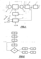
Fig.1 représente un schéma synoptique illustrant la structure générale d'un système d'aide à la régénération selon l'invention ; et - la
Fig.2 représente un organigramme illustrant le fonctionnement de celui-ci. - On a en effet illustré sur la
figure 1 , la structure générale d'un système d'aide à la régénération de moyens de dépollution, désignés par la référence générale 1 sur cette figure, associés à des moyens formant catalyseur d'oxydation désignés par la référence générale 2, et intégrés dans une ligne d'échappement 3, d'un moteur Diesel 4 de véhicule automobile. - Le moteur peut être associé à un turbocompresseur et dans ce cas, la portion de turbine 5 de celui-ci est également associée à cette ligne d'échappement, la portion du compresseur 6 du turbocompresseur étant placée en amont du moteur.
- Par ailleurs, ce moteur est également associé à des moyens 7 à rampe commune d'alimentation en carburant des cylindres de ce moteur, adaptés pour mettre en oeuvre, à iso-couple, une stratégie de régénération par injection de carburant dans les cylindres, selon au moins une post-injection, de façon classique.
- Ces moyens sont contrôlés par une unité de pilotage, désignée par la référence générale 8, adaptée pour détecter une requête de régénération req.RG, délivrée par exemple par un superviseur des moyens de dépollution, et donc de post-injection et raccordée à des moyens 9 de détection d'un état de lever de pied de l'accélérateur du véhicule et à des moyens de détection d'une phase de ralenti du moteur de celui-ci, désignés par la référence générale 10.
- Ces moyens peuvent présenter n'importe quelle structure appropriée.
- Par ailleurs, cette unité de pilotage 8 est également raccordée à des moyens d'acquisition de la température en aval des moyens formant catalyseur 2, ces moyens d'acquisition étant désignés par la référence générale 11.
- Ces moyens comprennent tout capteur de température approprié.
- Ceci permet alors, suite à la détection d'une requête de régénération et donc de post-injection, à cette unité de pilotage 8, de détecter un état de lever de pied de l'accélérateur du véhicule ou une phase de ralenti du moteur de celui-ci, comme cela est illustré par l'étape 12 sur la
figure 2 . - L'unité 8 est alors adaptée pour acquérir la température en aval des moyens formant catalyseur lors de l'étape 13 et pour déterminer une quantité maximale de carburant à injecter lors des post-injections durant les phases de retour au ralenti, consécutivement à un lever de pied de l'accélérateur ou de ralenti, à partir de cette température, lors de l'étape 14.
- L'unité 8 surveille alors en 15 et 16, la quantité de carburant injecté lors des post-injections, et détecte le moment où cette quantité de carburant injecté a atteint la quantité maximale prédéterminée.
- Si la quantité de carburant injecté a atteint la quantité maximale prédéterminée lors de la phase de retour au ralenti, consécutivement à un lever de pied de l'accélérateur, comme cela est illustré en 17, l'unité de pilotage 8 est adaptée pour couper immédiatement la ou chaque post-injection, comme cela est illustré par l'étape 18.
- Par contre, si la quantité de carburant injecté a atteint la quantité maximale prédéterminée lors de la phase au ralenti du moteur, comme cela est illustré par l'étape 19, l'unité de pilotage est adaptée pour réduire progressivement la ou chaque post-injection, selon une rampe par exemple calibrable en 20.
- On notera également qu'un tel système peut fonctionner avec des moyens de dépollution formés par un filtre à particules, un piège à NOx, et qu'un additif destiné à se déposer avec les particules auxquelles il est mélangé, sur les moyens de dépollution pour faciliter leur régénération peut également être mélangé au carburant, de façon classique, pour abaisser la température de combustion des suies piégées dans celui-ci.
- De façon classique, cet additif est en effet présent dans les particules après combustion du carburant additivé dans le moteur.
- Un additif formant piège à NOx peut également être envisagé.
- On conçoit alors que grâce à une telle structure, on autorise une quantité maximale de carburant lors de la post-injection pour les phases de ralenti et de lever de pied.
- Cette quantité maximale se présente sous la forme d'un réservoir qui se vide au fur et à mesure que l'on accumule les phases de ralenti et/ou de lever de pied durant la phase de régénération. Ce réservoir est réinitialisé à la fin des phases.
- Ainsi, ce système permet de limiter les quantités post-injectées lors des phases de lever de pied ou de ralenti lorsque les niveaux thermiques de la ligne d'échappement sont les plus défavorables.
- En limitant la quantité totale de carburant post-injecté pendant ces phases, qui ne sont pas les plus efficaces du point de vue de la régénération des moyens de dépollution, on optimise la proportion de temps de post-injection efficace et on limite la dilution de l'huile de lubrification du moteur par le carburant.
- Enfin, ceci permet également de limiter le risque que la fonction d'oxydation ne se désamorce subitement, ce qui se traduirait par un déficit de conversion des HC et donc une bouffée de HC à l'échappement pouvant générer des fumées et/ou des odeurs.
- Bien entendu, d'autres modes de réalisation peuvent être envisagés.
- Ainsi par exemple, les moyens de dépollution et les moyens formant catalyseur d'oxydation peuvent être intégrés dans un seul et même élément, notamment sur un même substrat.
- A titre d'exemple, un filtre à particules intégrant la fonction d'oxydation peut être envisagé.
- De même, un piège à NOx intégrant une telle fonction d'oxydation peut également être envisagé, que celui-ci soit additivé ou non. Cette fonction d'oxydation et/ou de piège à NOx peut être remplie par exemple par un additif mélangé au carburant.
Claims (5)
- Système d'aide à la régénération d'un filtre à particules (1) associé à des moyens formant catalyseur d'oxydation (2), et intégrés dans une ligne d'échappement (3) d'un moteur Diesel (4) de véhicule automobile et dans lequel le moteur (4) est associé à des moyens (7) à rampe commune d'alimentation en carburant de cylindres du moteur, adaptés pour mettre en oeuvre, à iso-couple, une stratégie de régénération par injection de carburant dans les cylindres selon au moins une post-injection, caractérisé en ce qu'il comporte :- des moyens (8) de détection d'une requête de régénération (req.RG) et donc de post-injection ;- des moyens (9,10) de détection d'un état de lever de pied de l'accélérateur du véhicule ou d'une phase de ralenti du moteur de celui-ci ;- des moyens (11) d'acquisition de la température en aval des moyens formant catalyseur (2) ;- des moyens (8) de détermination d'une quantité totale de carburant à injecter lors des post-injections durant les phases de retour au ralenti, consécutivement à un lever de pied de l'accélérateur et de ralenti, à partir de cette température ; et- des moyens (7,8) de coupure immédiate de la ou de chaque post-injection si la quantité de carburant injecté a atteint la quantité totale prédéterminée lors de la phase de retour au ralenti et/ou de réduction progressive de la ou de chaque post-injection, lorsque la quantité de carburant injecté a atteint la quantité totale prédéterminée lors de la phase de ralenti du moteur.
- Système selon la revendication 1, caractérisé en ce que les moyens de réduction (7,8) sont adaptés pour réduire la ou chaque post-injection selon une rampe calibrable (20).
- Système selon la revendication 1 ou 2, caractérisé en ce que le carburant comporte un additif destiné à se déposer avec les particules auxquelles il est mélangé, sur le filtre à particules (1) pour faciliter sa régénération.
- Système selon la revendication 1 ou 2, caractérisé en ce que le carburant comporte un additif formant piège à NOx.
- Système selon l'une quelconque des revendications précédentes, caractérisé en ce que le moteur est associé à un turbocompresseur (5,6).
Applications Claiming Priority (2)
| Application Number | Priority Date | Filing Date | Title |
|---|---|---|---|
| FR0313161A FR2862101B1 (fr) | 2003-11-07 | 2003-11-07 | Systeme d'aide a la regeneration de moyens de depollution integres dans une ligne d'echappement d'un moteur diesel de vehicule |
| PCT/FR2004/002503 WO2005049995A1 (fr) | 2003-11-07 | 2004-10-04 | Systeme d'aide a la regeneration de moyens de depollution integres dans une ligne d'echappement d'un moteur diesel de vehicule |
Publications (2)
| Publication Number | Publication Date |
|---|---|
| EP1680585A1 EP1680585A1 (fr) | 2006-07-19 |
| EP1680585B1 true EP1680585B1 (fr) | 2008-11-12 |
Family
ID=34508363
Family Applications (1)
| Application Number | Title | Priority Date | Filing Date |
|---|---|---|---|
| EP04791463A Active EP1680585B1 (fr) | 2003-11-07 | 2004-10-04 | Systeme d aide a la regeneration de moyens de depollution in tegres dans une ligne d echappement d un moteur diesel de vehicule |
Country Status (7)
| Country | Link |
|---|---|
| US (1) | US7370632B2 (fr) |
| EP (1) | EP1680585B1 (fr) |
| AT (1) | ATE414220T1 (fr) |
| DE (1) | DE602004017772D1 (fr) |
| ES (1) | ES2315717T3 (fr) |
| FR (1) | FR2862101B1 (fr) |
| WO (1) | WO2005049995A1 (fr) |
Cited By (1)
| Publication number | Priority date | Publication date | Assignee | Title |
|---|---|---|---|---|
| US11624333B2 (en) | 2021-04-20 | 2023-04-11 | Kohler Co. | Exhaust safety system for an engine |
Families Citing this family (5)
| Publication number | Priority date | Publication date | Assignee | Title |
|---|---|---|---|---|
| DE102004053041A1 (de) * | 2004-11-03 | 2006-05-04 | Daimlerchrysler Ag | Verfahren zum Betrieb einer Brennkraftmaschine mit einem SCR-Katalysator |
| JP3933172B2 (ja) * | 2005-07-15 | 2007-06-20 | いすゞ自動車株式会社 | 排気ガス浄化システムの制御方法及び排気ガス浄化システム |
| US8607549B2 (en) * | 2009-07-31 | 2013-12-17 | Ford Global Technologies, Llc | Controlling regeneration of an emission control device |
| US8752364B2 (en) * | 2009-09-30 | 2014-06-17 | Cummins Inc. | Techniques for optimizing engine operations during aftertreatment regeneration |
| SE534475C2 (sv) * | 2010-01-18 | 2011-09-06 | Scania Cv Ab | Förfarande och anordning för att förhindra bränsleansamling i ett avgassystem hos ett motorfordon |
Family Cites Families (12)
| Publication number | Priority date | Publication date | Assignee | Title |
|---|---|---|---|---|
| JPH11294220A (ja) * | 1998-04-13 | 1999-10-26 | Mitsubishi Electric Corp | 筒内噴射式内燃機関の燃料噴射制御装置 |
| DE19957185A1 (de) * | 1999-11-27 | 2001-05-31 | Volkswagen Ag | Verfahren und Vorrichtung zur Steuerung einer Aufheizphase zumindest eines in einem Abgaskanal einer Verbrennungskraftmaschine angeordneten Katalysators |
| FR2812034B1 (fr) * | 2000-07-21 | 2003-03-21 | Renault | Procede d'injection de carburant |
| JPWO2002066813A1 (ja) * | 2001-02-20 | 2004-06-24 | いすゞ自動車株式会社 | ディーゼルエンジンの燃料噴射制御方法と排気ガス後処理装置の再生制御方法 |
| ITTO20010786A1 (it) * | 2001-08-03 | 2003-02-03 | Fiat Ricerche | Metodo di autoinnesco della rigenerazione di un filtro particolato per un motore diesel ad iniezione diretta provvisto di un impianto di ini |
| JP2005083305A (ja) * | 2003-09-10 | 2005-03-31 | Mazda Motor Corp | エンジンの排気浄化装置 |
| FR2862096B1 (fr) * | 2003-11-07 | 2006-02-17 | Peugeot Citroen Automobiles Sa | Systeme d'aide a la regeneration de moyens de depollution integres dans une ligne d'echappement d'un moteur de vehicule |
| FR2862103B1 (fr) * | 2003-11-07 | 2006-02-17 | Peugeot Citroen Automobiles Sa | Systeme d'aide a la regeneration de moyens de depollution integres dans une ligne d'echapement d'un moteur diesel de vehicule automobile |
| FR2862099B1 (fr) * | 2003-11-07 | 2006-04-14 | Peugeot Citroen Automobiles Sa | Systeme d'aide a la regeneration de moyens de depollution integres dans une ligne d'echappement d'un moteur diesel de vehicule |
| FR2862098B1 (fr) * | 2003-11-07 | 2006-02-17 | Peugeot Citroen Automobiles Sa | Systeme d'aide a la regeneration de moyens de depollution integres dans une ligne d'echappement d'un moteur diesel de vehicule |
| FR2862100B1 (fr) * | 2003-11-07 | 2008-04-04 | Peugeot Citroen Automobiles Sa | Systeme d'aide a la regeneration de moyens de depollution integres dans une ligne d'echappement d'un vehicule |
| ITTO20030999A1 (it) * | 2003-12-12 | 2005-06-13 | Fiat Ricerche | Metodo di attivazione della rigenerazione di un filtro del particolato in base ad una stima della quantita' di particolato accumulata nel filtro del particolato. |
-
2003
- 2003-11-07 FR FR0313161A patent/FR2862101B1/fr not_active Expired - Fee Related
-
2004
- 2004-10-04 WO PCT/FR2004/002503 patent/WO2005049995A1/fr active Application Filing
- 2004-10-04 DE DE602004017772T patent/DE602004017772D1/de active Active
- 2004-10-04 ES ES04791463T patent/ES2315717T3/es active Active
- 2004-10-04 US US10/595,631 patent/US7370632B2/en not_active Expired - Fee Related
- 2004-10-04 EP EP04791463A patent/EP1680585B1/fr active Active
- 2004-10-04 AT AT04791463T patent/ATE414220T1/de not_active IP Right Cessation
Cited By (1)
| Publication number | Priority date | Publication date | Assignee | Title |
|---|---|---|---|---|
| US11624333B2 (en) | 2021-04-20 | 2023-04-11 | Kohler Co. | Exhaust safety system for an engine |
Also Published As
| Publication number | Publication date |
|---|---|
| ATE414220T1 (de) | 2008-11-15 |
| FR2862101A1 (fr) | 2005-05-13 |
| EP1680585A1 (fr) | 2006-07-19 |
| DE602004017772D1 (de) | 2008-12-24 |
| US7370632B2 (en) | 2008-05-13 |
| US20070056265A1 (en) | 2007-03-15 |
| WO2005049995A1 (fr) | 2005-06-02 |
| FR2862101B1 (fr) | 2006-04-14 |
| ES2315717T3 (es) | 2009-04-01 |
Similar Documents
| Publication | Publication Date | Title |
|---|---|---|
| EP1774144B1 (fr) | Systeme d'aide a la regeneration de moyens de depollution | |
| EP1680580B1 (fr) | Systeme d aide a la regeneration de moyens de depollution in tegres dans une ligne d echappement d un moteur diesel de vehicule | |
| EP1766202B1 (fr) | Systeme d'aide a la regeneration de moyens de depollution associes a des moyens formant catalyseur | |
| EP1682762B1 (fr) | Systeme d'aide a la regeneration de moyens de depollution integres dans une ligne d'echappement d'un moteur diesel de vehicule automobile | |
| EP1778962B1 (fr) | Système de contrôle de la régénération de moyens de dépollution | |
| EP1680585B1 (fr) | Systeme d aide a la regeneration de moyens de depollution in tegres dans une ligne d echappement d un moteur diesel de vehicule | |
| EP1680584B1 (fr) | Systeme d'aide a la regeneration de moyens de depollution integres dans une ligne d'echappement d' un vehicule | |
| EP1769140B1 (fr) | Systeme d'aide a la regeneration de moyens de depollution dans une ligne d'echappement d'un moteur | |
| EP1685319B1 (fr) | Systeme d'aide a la regeneration de moyens de depollution in tegres dans une ligne d'echappement d'un moteur diesel de vehicule | |
| WO2006005862A1 (fr) | Systeme d'aide a la regeneration de moyens de depollution associes a des moyens formant catalyseur | |
| EP1682760B1 (fr) | Systeme d' aide a la regeneration de moyens de depollution integres dans une ligne d'echappement d'un moteur diesel de vehicule | |
| EP1689994B1 (fr) | Systeme d'aide a la regeneration de moyens de depollution integres dans une ligne d'echappement d'un moteur diesel de vehicule | |
| WO2006005865A1 (fr) | Systeme d'aide a la regeneration de moyens de depollution integres dans une ligne d'echappement d'un moteur |
Legal Events
| Date | Code | Title | Description |
|---|---|---|---|
| PUAI | Public reference made under article 153(3) epc to a published international application that has entered the european phase |
Free format text: ORIGINAL CODE: 0009012 |
|
| 17P | Request for examination filed |
Effective date: 20060301 |
|
| AK | Designated contracting states |
Kind code of ref document: A1 Designated state(s): AT BE BG CH CY CZ DE DK EE ES FI FR GB GR HU IE IT LI LU MC NL PL PT RO SE SI SK TR |
|
| DAX | Request for extension of the european patent (deleted) | ||
| 17Q | First examination report despatched |
Effective date: 20070507 |
|
| GRAP | Despatch of communication of intention to grant a patent |
Free format text: ORIGINAL CODE: EPIDOSNIGR1 |
|
| GRAS | Grant fee paid |
Free format text: ORIGINAL CODE: EPIDOSNIGR3 |
|
| GRAA | (expected) grant |
Free format text: ORIGINAL CODE: 0009210 |
|
| AK | Designated contracting states |
Kind code of ref document: B1 Designated state(s): AT BE BG CH CY CZ DE DK EE ES FI FR GB GR HU IE IT LI LU MC NL PL PT RO SE SI SK TR |
|
| REG | Reference to a national code |
Ref country code: GB Ref legal event code: FG4D Free format text: NOT ENGLISH |
|
| REG | Reference to a national code |
Ref country code: CH Ref legal event code: EP |
|
| REG | Reference to a national code |
Ref country code: IE Ref legal event code: FG4D Free format text: LANGUAGE OF EP DOCUMENT: FRENCH |
|
| REF | Corresponds to: |
Ref document number: 602004017772 Country of ref document: DE Date of ref document: 20081224 Kind code of ref document: P |
|
| REG | Reference to a national code |
Ref country code: GB Ref legal event code: 746 Effective date: 20081222 |
|
| REG | Reference to a national code |
Ref country code: ES Ref legal event code: FG2A Ref document number: 2315717 Country of ref document: ES Kind code of ref document: T3 |
|
| PG25 | Lapsed in a contracting state [announced via postgrant information from national office to epo] |
Ref country code: AT Free format text: LAPSE BECAUSE OF FAILURE TO SUBMIT A TRANSLATION OF THE DESCRIPTION OR TO PAY THE FEE WITHIN THE PRESCRIBED TIME-LIMIT Effective date: 20081112 |
|
| NLV1 | Nl: lapsed or annulled due to failure to fulfill the requirements of art. 29p and 29m of the patents act | ||
| PG25 | Lapsed in a contracting state [announced via postgrant information from national office to epo] |
Ref country code: NL Free format text: LAPSE BECAUSE OF FAILURE TO SUBMIT A TRANSLATION OF THE DESCRIPTION OR TO PAY THE FEE WITHIN THE PRESCRIBED TIME-LIMIT Effective date: 20081112 Ref country code: PL Free format text: LAPSE BECAUSE OF FAILURE TO SUBMIT A TRANSLATION OF THE DESCRIPTION OR TO PAY THE FEE WITHIN THE PRESCRIBED TIME-LIMIT Effective date: 20081112 Ref country code: FI Free format text: LAPSE BECAUSE OF FAILURE TO SUBMIT A TRANSLATION OF THE DESCRIPTION OR TO PAY THE FEE WITHIN THE PRESCRIBED TIME-LIMIT Effective date: 20081112 Ref country code: SI Free format text: LAPSE BECAUSE OF FAILURE TO SUBMIT A TRANSLATION OF THE DESCRIPTION OR TO PAY THE FEE WITHIN THE PRESCRIBED TIME-LIMIT Effective date: 20081112 |
|
| REG | Reference to a national code |
Ref country code: IE Ref legal event code: FD4D |
|
| PG25 | Lapsed in a contracting state [announced via postgrant information from national office to epo] |
Ref country code: DK Free format text: LAPSE BECAUSE OF FAILURE TO SUBMIT A TRANSLATION OF THE DESCRIPTION OR TO PAY THE FEE WITHIN THE PRESCRIBED TIME-LIMIT Effective date: 20081112 Ref country code: IE Free format text: LAPSE BECAUSE OF FAILURE TO SUBMIT A TRANSLATION OF THE DESCRIPTION OR TO PAY THE FEE WITHIN THE PRESCRIBED TIME-LIMIT Effective date: 20081112 Ref country code: EE Free format text: LAPSE BECAUSE OF FAILURE TO SUBMIT A TRANSLATION OF THE DESCRIPTION OR TO PAY THE FEE WITHIN THE PRESCRIBED TIME-LIMIT Effective date: 20081112 Ref country code: RO Free format text: LAPSE BECAUSE OF FAILURE TO SUBMIT A TRANSLATION OF THE DESCRIPTION OR TO PAY THE FEE WITHIN THE PRESCRIBED TIME-LIMIT Effective date: 20081112 Ref country code: BG Free format text: LAPSE BECAUSE OF FAILURE TO SUBMIT A TRANSLATION OF THE DESCRIPTION OR TO PAY THE FEE WITHIN THE PRESCRIBED TIME-LIMIT Effective date: 20090212 |
|
| PG25 | Lapsed in a contracting state [announced via postgrant information from national office to epo] |
Ref country code: PT Free format text: LAPSE BECAUSE OF FAILURE TO SUBMIT A TRANSLATION OF THE DESCRIPTION OR TO PAY THE FEE WITHIN THE PRESCRIBED TIME-LIMIT Effective date: 20090413 Ref country code: CZ Free format text: LAPSE BECAUSE OF FAILURE TO SUBMIT A TRANSLATION OF THE DESCRIPTION OR TO PAY THE FEE WITHIN THE PRESCRIBED TIME-LIMIT Effective date: 20081112 Ref country code: SE Free format text: LAPSE BECAUSE OF FAILURE TO SUBMIT A TRANSLATION OF THE DESCRIPTION OR TO PAY THE FEE WITHIN THE PRESCRIBED TIME-LIMIT Effective date: 20090212 |
|
| PLBE | No opposition filed within time limit |
Free format text: ORIGINAL CODE: 0009261 |
|
| STAA | Information on the status of an ep patent application or granted ep patent |
Free format text: STATUS: NO OPPOSITION FILED WITHIN TIME LIMIT |
|
| PG25 | Lapsed in a contracting state [announced via postgrant information from national office to epo] |
Ref country code: SK Free format text: LAPSE BECAUSE OF FAILURE TO SUBMIT A TRANSLATION OF THE DESCRIPTION OR TO PAY THE FEE WITHIN THE PRESCRIBED TIME-LIMIT Effective date: 20081112 |
|
| 26N | No opposition filed |
Effective date: 20090813 |
|
| BERE | Be: lapsed |
Owner name: PEUGEOT CITROEN AUTOMOBILES SA Effective date: 20091031 |
|
| PG25 | Lapsed in a contracting state [announced via postgrant information from national office to epo] |
Ref country code: MC Free format text: LAPSE BECAUSE OF NON-PAYMENT OF DUE FEES Effective date: 20091031 |
|
| REG | Reference to a national code |
Ref country code: CH Ref legal event code: PL |
|
| PG25 | Lapsed in a contracting state [announced via postgrant information from national office to epo] |
Ref country code: CH Free format text: LAPSE BECAUSE OF NON-PAYMENT OF DUE FEES Effective date: 20091031 Ref country code: LI Free format text: LAPSE BECAUSE OF NON-PAYMENT OF DUE FEES Effective date: 20091031 Ref country code: GR Free format text: LAPSE BECAUSE OF FAILURE TO SUBMIT A TRANSLATION OF THE DESCRIPTION OR TO PAY THE FEE WITHIN THE PRESCRIBED TIME-LIMIT Effective date: 20090213 Ref country code: BE Free format text: LAPSE BECAUSE OF NON-PAYMENT OF DUE FEES Effective date: 20091031 |
|
| REG | Reference to a national code |
Ref country code: ES Ref legal event code: GC2A Effective date: 20110406 |
|
| PG25 | Lapsed in a contracting state [announced via postgrant information from national office to epo] |
Ref country code: LU Free format text: LAPSE BECAUSE OF NON-PAYMENT OF DUE FEES Effective date: 20091004 |
|
| PG25 | Lapsed in a contracting state [announced via postgrant information from national office to epo] |
Ref country code: HU Free format text: LAPSE BECAUSE OF FAILURE TO SUBMIT A TRANSLATION OF THE DESCRIPTION OR TO PAY THE FEE WITHIN THE PRESCRIBED TIME-LIMIT Effective date: 20090513 |
|
| PG25 | Lapsed in a contracting state [announced via postgrant information from national office to epo] |
Ref country code: TR Free format text: LAPSE BECAUSE OF FAILURE TO SUBMIT A TRANSLATION OF THE DESCRIPTION OR TO PAY THE FEE WITHIN THE PRESCRIBED TIME-LIMIT Effective date: 20081112 |
|
| PG25 | Lapsed in a contracting state [announced via postgrant information from national office to epo] |
Ref country code: CY Free format text: LAPSE BECAUSE OF FAILURE TO SUBMIT A TRANSLATION OF THE DESCRIPTION OR TO PAY THE FEE WITHIN THE PRESCRIBED TIME-LIMIT Effective date: 20081112 |
|
| PGFP | Annual fee paid to national office [announced via postgrant information from national office to epo] |
Ref country code: GB Payment date: 20130923 Year of fee payment: 10 |
|
| GBPC | Gb: european patent ceased through non-payment of renewal fee |
Effective date: 20141004 |
|
| PG25 | Lapsed in a contracting state [announced via postgrant information from national office to epo] |
Ref country code: GB Free format text: LAPSE BECAUSE OF NON-PAYMENT OF DUE FEES Effective date: 20141004 |
|
| REG | Reference to a national code |
Ref country code: FR Ref legal event code: PLFP Year of fee payment: 13 |
|
| PGFP | Annual fee paid to national office [announced via postgrant information from national office to epo] |
Ref country code: IT Payment date: 20160923 Year of fee payment: 13 Ref country code: ES Payment date: 20160922 Year of fee payment: 13 |
|
| REG | Reference to a national code |
Ref country code: FR Ref legal event code: PLFP Year of fee payment: 14 |
|
| REG | Reference to a national code |
Ref country code: FR Ref legal event code: CA Effective date: 20180312 Ref country code: FR Ref legal event code: CD Owner name: PEUGEOT CITROEN AUTOMOBILES SA, FR Effective date: 20180312 |
|
| REG | Reference to a national code |
Ref country code: FR Ref legal event code: PLFP Year of fee payment: 15 |
|
| PG25 | Lapsed in a contracting state [announced via postgrant information from national office to epo] |
Ref country code: IT Free format text: LAPSE BECAUSE OF NON-PAYMENT OF DUE FEES Effective date: 20171004 |
|
| REG | Reference to a national code |
Ref country code: ES Ref legal event code: FD2A Effective date: 20181220 |
|
| PG25 | Lapsed in a contracting state [announced via postgrant information from national office to epo] |
Ref country code: ES Free format text: LAPSE BECAUSE OF NON-PAYMENT OF DUE FEES Effective date: 20171005 |
|
| PGFP | Annual fee paid to national office [announced via postgrant information from national office to epo] |
Ref country code: DE Payment date: 20220616 Year of fee payment: 19 |
|
| PGFP | Annual fee paid to national office [announced via postgrant information from national office to epo] |
Ref country code: FR Payment date: 20230920 Year of fee payment: 20 |