EP1679656B1 - System und Verfahren zur Programmierung von unterbrechenden Operationen während der Erfassungs von Sequenzen von sich bewegenden Bildern - Google Patents
System und Verfahren zur Programmierung von unterbrechenden Operationen während der Erfassungs von Sequenzen von sich bewegenden Bildern Download PDFInfo
- Publication number
- EP1679656B1 EP1679656B1 EP05021845A EP05021845A EP1679656B1 EP 1679656 B1 EP1679656 B1 EP 1679656B1 EP 05021845 A EP05021845 A EP 05021845A EP 05021845 A EP05021845 A EP 05021845A EP 1679656 B1 EP1679656 B1 EP 1679656B1
- Authority
- EP
- European Patent Office
- Prior art keywords
- operations
- image acquisition
- incompatible
- sequence
- images
- Prior art date
- Legal status (The legal status is an assumption and is not a legal conclusion. Google has not performed a legal analysis and makes no representation as to the accuracy of the status listed.)
- Expired - Lifetime
Links
Images


Classifications
-
- G—PHYSICS
- G06—COMPUTING OR CALCULATING; COUNTING
- G06T—IMAGE DATA PROCESSING OR GENERATION, IN GENERAL
- G06T7/00—Image analysis
- G06T7/0002—Inspection of images, e.g. flaw detection
- G06T7/0004—Industrial image inspection
-
- G—PHYSICS
- G06—COMPUTING OR CALCULATING; COUNTING
- G06T—IMAGE DATA PROCESSING OR GENERATION, IN GENERAL
- G06T2207/00—Indexing scheme for image analysis or image enhancement
- G06T2207/30—Subject of image; Context of image processing
- G06T2207/30108—Industrial image inspection
- G06T2207/30164—Workpiece; Machine component
Definitions
- the invention relates generally to methods for operating a machine vision inspection system with a camera and stage that are movable relative to one another in multiple directions so as to scan and inspect selected features of a workpiece on the stage, and more particularly to systems and methods that permit a user to readily program system operations that are not compatible with moving (continuous) image acquisition, while also programming moving image acquisition sequences.
- Precision machine vision inspection systems can be utilized to obtain precise dimensional measurements of inspected objects and to inspect various other object characteristics.
- Such systems may include a computer, a camera and optical system, and a precision stage that is movable in multiple directions so as to allow the camera to scan the features of a workpiece that is being inspected.
- One exemplary prior art system that is commercially available is the QUICK VISION® series of PC-based vision systems and QVPAK® software available from Mitutoyo America Corporation (MAC), located in Aurora, IL.
- Machine vision inspection systems generally utilize automated video inspection.
- U.S. Patent No. 6,542,180 teaches some examples of automated video inspection.
- automated video inspection metrology instruments generally have a programming capability that allows an automatic inspection event sequence to be defined by the user for each particular workpiece configuration. This can be implemented either in a deliberate manner, such as text-based programming, for example, or through a recording mode which progressively "learns” the inspection event sequence by storing a sequence of machine control instructions corresponding to a sequence of inspection operations performed by a user, or through a combination of both methods. Such a recording mode is often referred to as “learn mode" or "training mode". Once the inspection event sequence is defined in “learn mode,” such sequence can then be used to automatically acquire (and additionally analyze or inspect) images of a workpiece during "run mode.”
- the machine control instructions including the specific inspection event sequence including image acquisition parameters, etc., are generally stored as a "part program” or "workpiece program” that is specific to the particular workpiece configuration.
- the ability to create part programs with instructions that perform a predetermined sequence of inspection operations provides several benefits, including enhanced inspection repeatability, as well as the ability to automatically execute the same part program repeatedly on one or more compatible machine vision inspection systems.
- US 2004/097160 discloses a method of determining defects in OLED devices having a plurality of pixels, each with its own emissive layer, which are capable of being excited by input light to produce an output colour light response, including illuminating one or more OLED devices or a portion of an OLED device with light in a predetermined portion of the spectrum so that the pixel emissive layers are excited to produce an output colour response for each pixel, capturing an image of the output light produced by the excited pixels and converting such captured light into a digital image; and determining device pixel size, shape, location, and emitted light intensity from the digital image and comparing such size, shape, location, and emitted light intensity with predetermined acceptable size, shape, location, and emitted light intensity ranges to determine whether there is a defect in the OLED device(s).
- US 6324298 discloses an automated defect inspection system that is used on patterned wafers, whole wafers, broken wafers, partial wafers, sawn wafers such as on film frames, JEDEC trays, Auer boats, die in gel or waffle packs, MCMs, etc. and is specifically intended and designed for second optical wafer inspection for such defects as metalization defects (such as scratches, voids, corrosion, and bridging), diffusion defects, passivation layer defects, scribing defects, glassivation defects, chips and cracks from sawing, solder bump defects, and bond pad area defects.
- metalization defects such as scratches, voids, corrosion, and bridging
- diffusion defects passivation layer defects
- scribing defects glassivation defects
- chips and cracks from sawing, solder bump defects, and bond pad area defects.
- US 6408429 discloses an vision system is provided for identifying and assessing features of an article.
- Systems are provide for developing feature assessment programs, which, when deployed, may inspect parts and/or provide position information for guiding automated manipulation of such parts.
- High-speed "in-line” vision inspection systems used in high-speed production lines have provided continuous-motion type image acquisition.
- in-line vision systems typically are dedicated to a single production line and acquire the "same" image over and over again, for successive workpieces on a conveyor system, for example.
- motion speed and strobe illumination parameters, etc. are the same.
- workpiece configurations and/or image acquisition parameters, etc. are rarely changed.
- programming methods for such systems have not facilitated rapid programming for an unlimited variety of workpieces, camera positions, image acquisition parameters, etc., by relatively unskilled users.
- a user typically creates a part program during "learn mode" by defining each image acquisition (for example, by controlling the vision system position, focus, magnification, lighting conditions, etc., to achieve a desired image on a video display) and then immediately defining operations based on that image, such as workpiece image inspection or analysis operations, etc.
- learn mode operations are then automatically or semi-automatically converted into corresponding part programming instructions by the machine vision system.
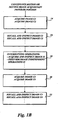
- This type of learn mode operation sequence referred to herein as the "ordinary” or “interspersed” learn mode, is schematically illustrated in FIGURE 1A .
- a user in the ordinary learn mode, at a block 2, first defines (or has the vision system "learn") how to acquire image C1 (e.g., how to position the camera relative to the workpiece, what light sources and lighting control parameters to use, etc.), and then defines (or has the vision system "learn") the operations that are to be performed based on the acquired image C1 (the "image C1 operations"), for example, inspection or analysis operations, etc.
- the user first defines (or has the vision system "learn") how to acquire image C2, and then defines (or has the vision system "learn") the operations that are to be performed based on the acquired image C2 (the "image C2 operations”), and so forth.
- the user defines (or has the vision system "learn") how to acquire image I1, and then defines (or has the vision system “learn") the operations that are to be performed based on the acquired image I1 (the "image I1 operations"), and so forth.
- the user defines an "image independent" operation, for example, a simple instruction or command to set the coordinate system origin at a particular location.
- the user defines operations similar to those previously described for blocks 2 and 4. According to conventional programming techniques, a part program created based on the foregoing examples of interspersed learn mode operations will perform the defined operations in a similar sequence of interspersed operations.
- FIGURE 1B schematically shows how a "continuous motion" or moving image acquisition portion of a program may be provided by programming at least some of the image acquisition operations defined during learn mode operations that are compatible with moving image acquisition (generally referred to as "compatible” or “compatible type” operations herein), which in this example are taken to be the image acquisition operations described with reference to blocks 2, 4, 10 and 12 of FIGURE 1A , to be arranged according to a non-interspersed type of sequence shown at blocks 14 and 20 of FIGURE 1B . Identifying "compatible" operations is described in greater detail further below.
- the compatible C 1 image acquisition operations are arranged into a non-interspersed instruction block 14 and the associated compatible C1 operations on that image are arranged into a subsequent instruction block 16.
- the compatible C2 image acquisition operations are arranged as the next elements into the non-interspersed instruction block 14 and the associated compatible type C2 operations on that image are arranged as the next elements in the subsequent instruction block 16.
- the compatible type operations of blocks 2 and 4 are followed by the operations of blocks 6 and 8, which are taken to be operations that are not compatible with a continuous motion type of moving image acquisition sequence (generally referred to as "incompatible” or “incompatible type” operations herein). Identifying "incompatible” operations is described in greater detail further below. Briefly stated, in this example, as the incompatible operations of block 6 are entered, they cause the non-interspersed instruction blocks 14 and 16, which include compatible operations, to be terminated. The instructions corresponding to the incompatible image I1 operations are arranged into an instruction block 18 in a conventional "interspersed" manner. In this case, the I1 image acquisition operation are followed by any associated incompatible image I1 operations on that image.
- an image-independent incompatible operation such as a command to set/reset the current coordinate system origin at a particular point in the global coordinate system, or the like, is entered at block 8, the associated instructions are simply arranged as the next elements in the interspersed instruction block 18.
- the incompatible type operations of blocks 6 and 8 are followed by the operations of blocks 10 and 12, which, in this example, are taken to be operations that are compatible with a continuous motion type of moving image acquisition sequence.
- the associated instruction are programmed into the non-interspersed instruction blocks 20 and 22, in the manner previously described for the compatible operation blocks 2 and 4 and the associated non-interspersed instruction blocks 14 and 16.
- FIGURE 1B In the programming structure or arrangement shown schematically in FIGURE 1B , at least some of the compatible type image analysis and/or inspection operations defined during learn mode operations, are programmed to be performed by acquiring a plurality of images using continuous motion, then subsequently recalling those images and performing the associated analysis/inspection operations.
- FIGURES 1A and 1B is just one example of a sequence of operations that is useful for illustrating terminology and concepts described in greater detail below. For example, it should be appreciated that if additional compatible operations similar to blocks 2 or 4 were performed following block 4 and before incompatible operation block 6, then the corresponding instructions would continue to be arranged as the next elements in the non-interspersed instruction blocks 14 and 16, before those blocks are terminated by the incompatible operations of block 6.
- the programming systems and methods disclosed herein accept multiple image acquisition operations interspersed with associated image analysis and/or inspection operations during learn mode operations and create a part program wherein the image acquisition operations for at least some of the images are arranged into a continuous motion image acquisition sequence that acquires images in a "non-interspersed" manner and the associated image analysis/inspection operations are performed subsequently on those acquired images.
- the programming systems and methods disclosed herein may operate automatically to facilitate rapid programming for a variety of workpieces by relatively unskilled users, wherein the resulting programs include continuous motion image acquisition sequences.
- not all image acquisition operations and associated image analysis and/or inspection operations are suited to being segregated into continuously motion image acquisition sequences and subsequent image analysis sequences. For example, if an image of a certain point on a workpiece is to be acquired at a magnification that is different from a previous image, then certain hardware adjustments to change the magnification must occur prior to acquiring such an image. Assuming that the hardware adjustment takes time (perhaps an unspecific amount of time, depending on each vision system), it would be best to stop the camera movement during the hardware adjustment to ensure that the hardware adjustment is complete when the image acquisition actually takes place.
- this type of image acquisition operation is incompatible with continuous (moving) image acquisition, and such an operation (perhaps as combined with an associated image analysis/inspection operation) is an incompatible image acquisition operation, or an incompatible operation, for short.
- an operation (perhaps as combined with an associated image analysis/inspection operation) is an incompatible image acquisition operation, or an incompatible operation, for short.
- the continuous relative motion between the camera and the workpiece must be stopped (or interrupted) to insure that proper image acquisition conditions are obtained and/or that certain image analysis or inspection operations are performed according to a required sequence as a pre-condition to obtaining the appropriate results from subsequent image acquisition and/or analysis operations.
- the programming systems and methods disclosed herein accept multiple image acquisition operations interspersed with associated image analysis and/or inspection operations during learn mode operations and create a part program wherein the image acquisition operations for at least some of the images are arranged into a continuous motion image acquisition sequence that acquires images in a "non-interspersed" manner and the associated image analysis/inspection operations are performed subsequently on those acquired images, and wherein the part program is further created to include one or more portions wherein certain other image acquisition operations and the associated image analysis and/or inspection operations are interspersed, at least when such operations are incompatible with continuous motion image acquisition.
- the programming systems and methods disclosed herein may operate automatically to facilitate rapid programming for a variety of workpieces by relatively unskilled users, wherein the resulting programs include both non-interspersed continuous motion image acquisition sequences, as well as any necessary interspersed image acquisition and analysis or inspection operation sequences.
- the programming systems and methods disclosed herein allow a user to program a general-purpose machine vision inspection system using a consistent learn mode procedure regardless of whether certain image acquisition operations are to be interspersed with (or "interrupted” by) image analysis and/or feature inspection operations (in the conventional manner), or whether continuous relative motion is used to provide higher throughput by acquiring certain images without interspersing image analysis operations that interrupt image acquisition operations.
- the programming systems and methods disclosed herein automatically re-sequence certain learn mode operations that were performed in an interspersed manner, to provide at least one programmed non-interspersed continuous motion image acquisition sequence, while certain incompatible learn mode operation sequences are programmed as interspersed sequences.
- the present invention offers methods and systems that permit a user to define both compatible and incompatible operations during learn mode, and produce a part program that incorporates moving image acquisition sequences as much as possible while at the same time ensuring to interrupt the moving image acquisition whenever an incompatible operation is called for.
- the system provides such a program in a manner that is fully transparent to the user, that is, the user need not consider whether various operations are compatible or incompatible.
- a user interface is provided that allows the user to determine whether the machine vision inspection system operates in a mode that automatically re-sequences certain compatible learn mode operations that were performed in an interspersed manner, to provide at least one programmed non-interspersed continuous motion image acquisition sequence, or whether the machine vision inspection system operates in a conventional mode to create a part program that generally consists of the conventional type of interspersed program instructions.
- the methods of the present invention may be embodied in a computer-readable medium and/or a carrier wave or other signal comprising computer executable instructions for performing the method, and the instructions may be loaded to and executed by a control system portion of a precision machine vision inspection system.
- the present invention includes a method of interpreting and/or compiling computer executable instructions for controlling a precision machine vision inspection system to inspect a workpiece, comprising generally two steps.
- First, the method permits a user to define both compatible and incompatible operations without intentionally segregating the operations.
- Second, the method automatically arranges the user-defined operations into different types of program instructions.
- a first type of instructions comprises a moving image acquisition instruction sequence or routine and an associated image analysis/inspection instruction sequence or routine that is executed at some time after images are available based on the image acquisition instruction sequence.
- the moving image acquisition routine comprises a set of machine control instructions for acquiring a set of workpiece images while maintaining a relative motion between the camera and the workpiece stage.
- the image analysis/inspection routine consists of a set of machine control instructions for analyzing/inspecting the acquired set of workpiece images.
- a second type of instructions comprises at least one instruction sequence or routine that controls the machine vision inspection system to perform at least one "incompatible operation", that is, an interspersed sequence of image acquisition and analysis or inspection operations that is incompatible with maintaining a relative motion between the camera and the workpiece.
- FIGURE 2 is a block diagram of one exemplary machine vision inspection system 10 in accordance with the present invention.
- the machine vision inspection system 10 includes a vision measuring machine 12 that is operably connected to exchange data and control signals with a controlling computer system 14.
- the controlling computer system 14 is further operably connected to exchange data and control signals with a monitor 16, a printer 18, a joystick 22, a keyboard 24, and a mouse 26.
- the vision measuring machine 12 includes a moveable workpiece stage 32 and an optical imaging system 34 which may include a zoom lens or interchangeable lenses.
- the zoom lens or interchangeable lenses generally provide various magnifications for the images provided by the optical imaging system 34.
- the joystick 22 can typically be used to control the movement of the movable workpiece stage 32 in both X and Y directions, which are generally parallel to the focal plane of the optical imaging system 34.
- the joystick 22 can also control the movement of the movable optical imaging system 34 in the Z or focus direction.
- the joystick 22 may be provided in a form other than that shown, such as any visual representation or widget on the monitor 16 which is intended to function as a "virtual motion control device" of the machine vision inspection system 10 and is controllable through any computer input device such as the mouse 26 or the like.
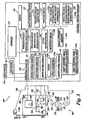
- FIGURE 3 is a diagram of a control system portion 120 and a vision components portion 200 of a machine vision inspection system 100 in accordance with the present invention.
- the vision components portion 200 includes an optical assembly portion 205, light sources 220, 230 and 240, and a workpiece stage 210 having a central transparent portion 212.
- the workpiece stage 210 is controllably movable along X and Y axes that lie in a plane that is generally parallel to the surface of the stage where a workpiece 20 may be positioned.
- the optical assembly portion 205 includes a camera system 260, an interchangeable objective lens 250, a turret lens assembly 280, and the coaxial light source 230.
- the optical assembly portion 205 is controllably movable along a Z axis that is generally orthogonal to the X and Y axes, by using a controllable motor 294.
- a workpiece 20 that is to be imaged using the machine vision inspection system 100 is placed on the workpiece stage 210.
- One or more of the light sources 220, 230 and 240 emits source light 222, 232, or 242, respectively, that is usable to illuminate the workpiece 20.
- Light emitted by the light sources 220, 230 and/or 240 illuminates the workpiece 20 and is reflected or transmitted as workpiece light 255, which passes through the interchangeable objective lens 250 and the turret lens assembly 280 and is gathered by the camera system 260.
- the image of the workpiece 20, captured by the camera system 260 is output on a signal line 262 to the control system portion 120.
- the light sources 220, 230, and 240 that are used to illuminate the workpiece 20 can include a stage light 220, a coaxial light 230, and a surface light 240, such as a ring light or a programmable ring light, all connected to the control system portion 120 through signal lines or busses 221, 231 and 241, respectively.
- the optical assembly portion 205 may include, in addition to the previously discussed components, other lenses, and other optical elements such as apertures, beamsplitters and the like, such as may be needed for providing coaxial illumination, or other desirable machine vision inspection system features.
- the turret lens assembly 280 includes at least a first turret lens position and lens 286 and a second turret lens position and lens 288.
- the control system portion 120 rotates the turret lens assembly 280 along axis 284, between at least the first and second turret lens positions, through a signal line or bus 281.
- the distance between the workpiece stage 210 and the optical assembly portion 205 can be adjusted to change the focus of the image of the workpiece 20 captured by the camera system 260.
- the optical assembly portion 205 is movable in the vertical Z axis direction relative to the workpiece stage 210 using a controllable motor 294 that drives an actuator, a connecting cable, or the like, to move the optical assembly portion 205 along the Z axis.
- the term Z axis refers to the axis that is intended to be used for focusing the image obtained by the optical assembly portion 205.
- the controllable motor 294 when used, is connected to the input/output interface 130 via a signal line 296.
- control system portion 120 includes a controller 125, an input/output interface 130, a memory 140, a workpiece program generator and executor 170, a CAD file feature extractor 180, and a power supply portion 190. It will be appreciated that each of these components, as well as the additional components described below, may be interconnected by one or more data/control buses and/or application programming interfaces, or by direct connections between the various elements.
- the input/output interface 130 includes an imaging control interface 131, a motion control interface 132, a lighting control interface 133, and a lens control interface 134.
- the motion control interface 132 includes a position control element 132a, and a speed/acceleration control element 132b.
- the lighting control interface 133 includes light control elements 133a-133n which control, for example, the selection, power, on/off switch, and strobe pulse timing if applicable, for the various corresponding light sources of the machine vision inspection system 100, such as the light sources 220, 230, and 240.
- the memory 140 includes an image file memory portion 141, a workpiece program memory portion 142, and a video tool portion 143.
- the video tool portion 143 includes tool portions 143a-143m, which determine the GUI, image processing operation, etc., for each of the corresponding tools. Any of tool portions 143a-143m may also include motion compatibility information usable to determine whether the operations associated with the video tool are compatible with a moving image acquisition mode of operation, so that the tool can be properly programmed according to the principles of this invention, as outlined in greater detail below.
- the motion compatibility information may be inherent in the general operation instructions associated with the tool, and general operation instructions may be analyzed by a continuous motion mode instruction generating portion 172 of the workpiece program generator and executor 170, in order to determine whether they are compatible with a continuous motion mode of operation.
- the motion compatibility information may comprise specific motion compatibility information such as a pre-determined compatibility or incompatibility code, or a program branching, address, or subroutine selecting instruction. In either case, the motion compatibility information causes the video tool operations to be programmed in the appropriate interspersed or non-interspersed manner by the continuous motion mode instruction generating portion 172 of the workpiece program generator and executor 170, as previously outlined and discussed in greater detail below.
- the video tool portion 143 also includes a region of interest generator 143x that supports automatic, semi-automatic and/or manual operations that define various regions of interest that are operable in various video tools included in the video tool portion 143.
- the memory portion 140 stores data usable to operate the vision system components portion 200 to capture or acquire an image of the workpiece 20 such that the acquired image of the workpiece 20 has desired image characteristics.
- the memory portion 140 further stores data usable to operate the machine vision inspection system 100 to perform various inspection and measurement operations on the acquired images, either manually or automatically, and to output the results through the input/output interface 130.
- the memory portion 140 also contains data defining a graphical user interface operable through the input/output interface 130.
- the signal lines or busses 221, 231 and 241 of the stage light 220, the coaxial light 230, and the surface light 240, respectively, are all connected to the input/output interface 130.
- the signal line 262 from the camera system 260 and the signal line 296 from the controllable motor 294 are connected to the input/output interface 130.
- the signal line 262 may carry a signal from the controller 125 that initiates image acquisition.
- One or more display devices 136 and one or more input devices 138 can also be connected to the input/output interface 130.
- the display devices 136 and input devices 138 can be used to view, create and/or modify part programs, to view the images captured by the camera system 260, and/or to directly control the vision system components portion 200.
- CAD file feature extractor 180 information such as a CAD file representing a workpiece, or a previous image of a substantially identical workpiece, is frequently available in industrial applications of machine vision inspection systems. In such cases, the CAD file representation or previous image may be used to facilitate off-line part programming.
- the control system portion 120 is usable to determine image acquisition settings and/or acquire an image of the workpiece 20 such that the input image of the workpiece 20 has desired image characteristics in a region of interest that includes a workpiece feature to be inspected.
- the user when a user uses the machine vision inspection system 100 to create a workpiece image acquisition program for the workpiece 20, the user generates workpiece program instructions either by explicitly coding the instructions automatically, semi-automatically, or manually, using a workpiece programming language, or by generating the instructions by moving the machine vision inspection system 100 through an image acquisition training sequence such that the workpiece program instructions capture the training sequence as outlined above.
- these instructions will cause the machine vision inspection system to manipulate the workpiece stage 210 and/or the camera system 260 such that a particular portion of the workpiece 20 is within the field of view of the camera system 260 and at a desired focus state.
- the instructions will also select a lens having a desired magnification and activate one or more of the light sources 220-240 to provide a desired illumination of the workpiece 20 during image acquisition.
- the instructions will also define various analysis or inspection operations to be performed on the resulting image.
- the present invention offers methods that permit the user to enter a mixture of operations that are either compatible or incompatible with moving image acquisition during learn mode operations, and the corresponding operations will be automatically programmed into a part program that includes continuous motion image acquisition sequences, in order to increase throughput during execution of the part program.
- the control system 120 commands the camera system 260 to capture each image of the workpiece 20 in the set and output the captured images to the control system portion 120.
- the control system portion 120 will then, under control of the controller 125, input the captured images through the input/output interface 130 and store the captured images in the image file memory portion 141 for subsequent analysis or inspection.
- the controller 125 may also display the captured images on the display device 136.
- the control system portion 120 is usable to analyze and inspect workpiece features in such workpiece inspection images, or in images acquired during non-compatible operations, and to store and/or output the inspection results or perform other appropriate operations based on the analysis or inspection results.
- the user when a user uses the machine vision inspection system 100 to create a workpiece image analysis/inspection program for the workpiece 20 according to this invention, the user typically generates program instructions by moving the machine vision inspection system 100 through an image acquisition and analysis/inspection training sequence such that the workpiece program instructions capture the training sequence and various systems and methods according to this invention arrange the associated part program instructions to facilitate increased inspection throughput as outlined above and described in greater detail below.
- the required image acquisition(s) and associated analysis/inspection operation(s) will be performed in an interspersed, sequential, or nearly sequential manner.
- these instructions will cause the machine vision inspection system to first sequentially acquire or capture and store a set of images without interrupting the acquisition sequence to perform analysis or inspection operations, that is, in a non-interspersed manner, and later recall the captured workpiece inspection image stored in the image file memory portion 141 of the memory 140 and perform various analysis/inspection operations on the images using the capabilities provided by various video tools included in the video tool portion 143 of the memory 140.
- Some of the types of video tools that may be compatible with a moving image acquisition mode of operation may include, for example, shape or pattern matching tools, edge and/or boundary detection tools, circle and dimension measuring tools, and the like. Such tools are routinely used and included in a variety of commercially available machine vision inspection systems, such as the QUICK VISION® series of vision systems and the associated QVPAK® software discussed above.
- the control system 120 will output the results of each analysis/inspection operation to the input/output interface for outputting to various display devices 136, which may include video display, printers, and the like.
- the control system 120 may also store the results of each inspection operation in the memory 140.
- a user be able to program a general-purpose machine vision inspection system using a consistent programming procedure regardless of whether image acquisition operations are to be interspersed with (or "interrupted” by) image analysis and/or feature inspection operations (in the conventional manner), or whether continuous relative motion is used in order to provide higher throughput by acquiring one or more images without interspersing image analysis operations that interrupt image acquisition operations. For example, if an image of a certain point in a workpiece is to be acquired at a different magnification from the rest of the workpiece, then certain hardware adjustments to change the magnification, and possibly to readjust the focus by autofocusing, must occur prior to acquiring such an image.
- any preceding continuous relative motion image acquisition sequence must be stopped (or interrupted) prior to and during performance of such incompatible operation(s) (in this case the magnification alteration and/or autofocus operations), then, if subsequent operations are compatible with a moving image acquisition, a subsequent moving image acquisition mode of operations may be initiated or resumed.
- the present invention is directed to improving the part programming available for continuous-motion type vision systems, by automatically generating part programs that generally include the two previously discussed types of operations: compatible operations to be performed in a manner that includes moving image acquisition sequences, and incompatible (interrupting) operations, without requiring the user to distinguish between the two types of operations during learn mode operations.
- the user need not manually (or consciously) switch or change their style of learn mode operation input in order to define a program that arranges compatible operation sequences along with incompatible operations in a part program.
- a method of the present invention is embodied in computer executable instructions stored in the workpiece program generator and executor 170 and/or its continuous motion mode instruction generating portion 172.
- the method generally includes three steps. First, the system enters a moving image acquisition or continuous motion learn mode, wherein acquisition and analysis/inspection of a set of images compatible with moving image acquisition can be defined.
- the operation is determined if the operation is compatible with moving image acquisition. If the operation (or a set of operations) is determined to be compatible, the associated image acquisition is included in a moving image acquisition sequence, which comprises a set of machine control instructions for acquiring and storing a set of workpiece images. Also, the associated analysis/inspection operations are included in an image recall and analysis sequence, which comprises a set of machine control instructions for recalling and analyzing/inspecting the set of stored workpiece images.
- a set of instructions is established that executes outside of the moving image acquisition sequence, which comprises a set of machine control instructions for performing the incompatible operation including both acquisition and analysis/inspection of an image or images.
- the second step is repeated as necessary in order to program each of the part program operations to be defined for the workpiece.
- an automatic part program generation system or method is structured such that once an operation is determined to be incompatible with moving image acquisition, the part program generation system or method automatically exits a moving image acquisition sequence programming mode to permit the user to define the incompatible operation outside that mode (e.g., in the ordinary "interspersed" learn mode). Likewise, after the incompatible operation is defined, if another operation (or a set of operations) is determined to be compatible with moving image acquisition, the system or method automatically reenters the moving image acquisition sequence programming mode to define sequential acquisition of a set of images and the subsequent recall and analysis/inspection operations.
- the exiting from and (re)entry into the moving image acquisition sequence programming mode is fully transparent to the user, who may simply follow ordinary learn mode programming procedures, while the part programming systems and methods according to this invention automatically streamline certain compatible operations to include one or more continuous motion image acquisition sequences.
- the determination as to whether an operation is compatible or incompatible with moving image acquisition is made automatically without a user input.
- a set of operations associated with a video tool or the like may be predetermined as incompatible with moving image acquisition and related predetermined information such as an "incompatibility flag" or a prestructured instruction sequence, may be stored in the system memory, for example in the video tool memory portion 143, or the like.
- the workpiece program generator and executor 170 can automatically exit a moving image acquisition programming mode, for example by controlling or disabling operation of the continuous motion mode instruction generating portion 172, whenever a user requests to define one of these predetermined incompatible operations, and generate the appropriate "interspersed" operation sequence.
- the continuous motion mode instruction generating portion 172 may be structured to analyze the inherent operations for a video tool or other machine vision inspection system tool and determine whether they are compatible with a moving image acquisition sequence, and generate the appropriate "non-interspersed” or “interspersed” operation sequence, accordingly.
- some of the operations that can be either predetermined or analyzed by the continuous motion mode instruction generating portion 172 as incompatible with moving image acquisition may include: (1) a variable motion operation which involves moving the camera relative to the workpiece but the actual relative movement may vary depending on each execution at run time, (2) an operation whose time for completion depends on the particular system's hardware specifics, (3) an operation that requires information to be derived from immediate image analysis at run time, (4) an operation that involves taking plural images at the same location on the workpiece, and (5) "image independent" coordinate system changes, e.g., in various embodiments, an instruction to "Translate" the coordinate system origin to a global or current coordinate of (100,0,0), and/or "Rotate" the coordinate system by 45 degrees, is treated as an incompatible operation.
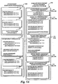
- FIGURE 4A is a flow diagram illustrative of one exemplary method (or routine) 300 for creating a part program for a vision system that includes continuous-motion image acquisition sequences along with operations incompatible with moving image acquisition.
- the method or routine 300 generally starts when learn mode operations are started and it is desired that the part program resulting from learn mode operations should include moving image acquisition sequences.
- a block 302 for each of a set of image acquisition and analysis/inspection operations to be defined, it is commanded that the following blocks 304-312 are to be performed.
- a decision block 304 it is determined whether the current operation or current operation set to be defined (such as the set of operations associated with a video tool, for example) is compatible with a moving image acquisition sequence or a moving image acquisition mode of operation. As described above, some operations are incompatible with moving image acquisition such that it is advantageous to stop the relative movement between the camera and the workpiece in association with performing such incompatible operations.
- an operation may be determined to be incompatible if the operation calls for the use of a certain set of hardware systems or hardware operations (e.g., to move a lens system to change magnification), or a certain set of software systems or image processing operations (e.g., to perform an autofocus operation or determine a coordinate system based on a current image when the coordinate system is to be used for future operations, or the like.)
- a certain set of hardware systems or hardware operations e.g., to move a lens system to change magnification
- software systems or image processing operations e.g., to perform an autofocus operation or determine a coordinate system based on a current image when the coordinate system is to be used for future operations, or the like.
- a user may specify each operation as either compatible or not when defining the operation, according to previously described criteria or any other criteria that the user feels are appropriate.
- operations are incompatible with moving image acquisition if they lead to variable results when executed at run time, if they modify the execution of later acquisition or analysis operations (e.g. Part Coordinate System changes or "PCS" changes, described further below), or if they are best executed while the camera is held stationary relative to the workpiece.
- Compatibility may be indicated and/or chosen, for example, by selecting a checkbox in a graphical user interface window or menu related to the operation, or the like.
- the determination of compatibility may be made automatically and then confirmed by a user manually or semi-automatically.
- a plurality of general categories may be applied to determine whether any operation is compatible or not with moving image acquisition.
- the operations described with reference to FIGURE 4B may be used for the operations of block 304 in various embodiments.
- alternative methods for performing block 304 are also described herein and further alternatives may be devised by one skilled in the art based on the information in this disclosure.
- operation proceeds to block 306, where the image acquisition operations are programmed as part of a moving image acquisition sequence and to block 308 where the associated analysis/inspection operations for the image are programmed as part of a sequence of operations that recalls the stored image subsequent to its acquisition and storage, and then analyzes and/or inspects it according to the defined operations.
- an operation is determined to be incompatible with a moving image acquisition sequence at block 304, then operation proceeds to block 310, where an image acquisition operation and the associated analysis/inspection operation(s) for the image are programmed as part of a sequence where at least one axis of relative motion is stopped or reduced to an insignificant speed in association with the incompatible image acquisition and analysis/inspection operation.
- an image acquisition operation and the associated analysis/inspection operation(s) for the image are programmed as part of a sequence where at least one axis of relative motion is stopped or reduced to an insignificant speed in association with the incompatible image acquisition and analysis/inspection operation.
- FIGURE 4A if a previous set of operations were programmed as part of a "current" non-interspersed image acquisition sequence, that sequence is generally interrupted or ended by the operations of the block 310.
- operation proceeds to decision block 312 where it is determined whether there are additional images acquisitions and/or analysis/inspection operations to be performed. If it is determined at block 312 that there are further operations to be included in the current part program, such as may be indicated by the user entering additional operations in learn mode, for example, then operation returns to block 304 where the method continues. Otherwise, if it is determined at block 312 that there are no further operations to be included in the current part program, such as may be indicated by the user terminating learn mode, for example, then operation proceeds to block 314 where the part program instructions resulting from the previous steps are saved for future use, and the method or routine 300 ends.
- FIGURE 4B is a flow chart illustrating one exemplary method or routine 340 for determining whether a particular operation is compatible or not with moving image acquisition.
- the embodiment shown in FIGURE 4B uses five general categories to identify incompatible operations, and is usable to provide one method for performing the block 304 shown in FIGURE 4A .
- the method or routine 340 generally starts when a set of image acquisition and analysis/inspection operations are defined in learn mode, then at block 341 it is commanded that operations corresponding to the following decision blocks 342-346 are to be performed.
- variable motion type of operation i.e., an operation that involves moving or adjusting the camera relative to the workpiece although the actual movement or adjustment may vary at least in part at run time.
- variable motion operations include, but are not limited to, an AutoFocus operation and AutoTrace operation. Briefly, the AutoFocus operation involves taking plural images of a portion of the workpiece while adjusting the camera along the Z axis relative to the workpiece, and based on the analysis of the acquired images selecting the camera position that produced the best-focused image.
- the AutoTrace operation involves following the edge or boundary (or a set of reference points) of an object feature on the workpiece. Both operations are routinely included and used in the QUICK VISION® series of vision systems and the associated QVPAK® software, discussed above. Both of these operations require moving the camera relative to the workpiece, but the precise movement of the camera will vary at run time depending on each workpiece being inspected. Further, during the AutoFocus operation, an optimal focus position (along the Z axis) is best determined when the camera has no X-Y motion relative to the workpiece. Accordingly, variable motion operations are not compatible with a moving image acquisition sequence.
- an operation is determined to be a variable motion operation at block 342, in various embodiments it is subsequently programmed as an incompatible and/or interspersed set of part program instructions, for example by proceeding to block 310 of FIGURE 4A , as shown.
- an operation is determined to be a variable motion operation at block 342
- it is subsequently programmed as an incompatible and/or interspersed set of part program instructions, for example by proceeding to block 310 of FIGURE 4A , as shown.
- FIGURES 5A and 5B One possible embodiment of programming incompatible and/or interspersed part program instructions, as well as compatible and/or non-interspersed part program instructions, is described with reference to FIGURES 5A and 5B , below.
- operation continues with decision block 343, where it is determined whether the operation is of a type such that the time needed to complete the operation depends on particular hardware systems performance or timing characteristics that vary between specific vision systems or types of visions systems that may be used to implement the part program, or that are otherwise not reliably predictable at the time of part programming. For example, an operation that changes the image the camera sees, and that might not be completed before the associated image is acquired, is incompatible. Examples of such operations include an operation to change the magnification of the vision system, or to rotate the workpiece stage (or index table).
- the time involved to complete these operations varies, from time to time even within the same system, and image acquisition will fail to be at the proper location on the workpiece, or may otherwise produce an unpredictable result, if the necessary hardware operation is not completed in time for the image acquisition.
- operation continues with decision block 344, where it is determined whether the current operation requires information to be derived from "immediate" image analysis. If so, such an operation is incompatible with moving image acquisition. Examples of this type of operation include an operation to align a coordinate system (e.g., Part Coordinate System) to a particular set of features located in an image of a current workpiece.
- a coordinate system e.g., Part Coordinate System
- this operation involves generally three steps: loading Part Coordinate System (PCS) set up instructions from memory or a disk; aligning the PCS depending on one or more workpiece feature locations determined in a desired workpiece image; and establishing the workpiece image-dependent PCS as the coordinate system to be used when interpreting the coordinate values specified or referenced in subsequent part program instructions within the part program, whether for the same image or additional images.
- PCS Part Coordinate System
- the operation is determined to be incompatible with moving image acquisition, and is subsequently programmed as an incompatible and/or interspersed set of part program instructions, for example by proceeding to block 310 of FIGURE 4A , as shown.
- decision block 345 it is determined whether an operation involves taking plural images at the same location on the workpiece, for example to optimize lighting conditions.
- Examples of such operations include a Brightness control operation, Dual Area Contrast control operation, and Lighting Wizard operation, or the like.
- Such operations are exemplified in the previously referenced commercially available QUICK VISION® series of PC-based vision systems and QVPAK® software available from Mitutoyo America Corporation (MAC), located in Aurora, IL., for example.
- the Dual Area Contrast control operation involves repeated analysis of relative contrast of two adjacent areas in an image, in order to optimize the contrast between them and thus enhance the definition of an edge located between the two areas.
- the Lighting Wizard operation involves taking several images at different combinations of lighting settings, simulating and interpolating further various combinations of lighting settings by selectively superimposing the images, and identifying a combination of lighting settings based on the best real and/or simulated/interpolated image, such that the lights settings provide optimal or sufficient lighting conditions for acquiring an image.
- Each of these operations involves taking several images and determining optimal lighting conditions based on the comparative analysis of the several images. These operations are best performed while the camera is held stationary relative to the workpiece so as to obtain several properly comparable images of the same location.
- an operation is determined to be within this category of operations at block 345, the operation is determined to be incompatible with moving image acquisition, and is subsequently programmed as an incompatible and/or interspersed set of part program instructions, for example by proceeding to block 310 of FIGURE 4A , as shown.
- PCS Part Coordinate System
- Such operations also include "image independent" coordinate system changes, e.g., in various embodiments, a command to "Translate” the coordinate system origin to a global or current coordinate position of (100,0,0), and/or "Rotate" the coordinate system by 45 degrees.
- an operation is determined to be within this category of operations at block 346, the operation is determined to be incompatible with moving image acquisition, and is subsequently programmed as an incompatible and/or interspersed set of part program instructions, for example by proceeding to block 310 of FIGURE 4A , as shown. Otherwise, if an operation is determined not to be of any of the respective types of operations analyzed at the respective blocks 342-346, then it is determined to be compatible with a moving image acquisition sequence of operations, and it is subsequently programmed as a compatible and/or non-interspersed set of part program instructions, for example by proceeding to block 306 of FIGURE 4A , as shown.
- PCS operations might alternatively be categorized as either “immediate image analysis” operations, or “coordinate system altering” operations, or both.
- various autofocus operations might alternatively be categorized as either “immediate image analysis” operations, or “plural images at the same location” operations, or both.
- the method of determining whether an operation is compatible with a moving image acquisition sequence or not is not limited to the sample method described with reference to FIGURE 4B , and systems that use fewer or more categories, or even methods that do not make use of "categorization" may be devised. Furthermore, while the determination may preferably be made fully automatically in various implementations, it may also be carried out manually, or semi-automatically, in various other implementations or applications.
- FIGURE 5A schematically illustrates a set of learn mode image acquisition and analysis/inspection operations 350 entered by a user in an interspersed manner, together with a corresponding schematically represented portion of a first embodiment of a set of part program instructions 370 according to one exemplary method of part program instruction sequencing in accordance with this invention.
- a user enters an interspersed set of image acquisition operations (e.g., how to position the camera relative to the workpiece, what light sources and lighting control parameters to use, etc.) and analysis/inspection operations that include a set of image C1 acquisition and analysis operations 353, a set of image C2 acquisition and analysis operations 354, and a set of C3 image-independent operations 355, each of which are taken here to consist of operations that are compatible with a moving image acquisition sequence of operations according to principles described herein.
- image acquisition operations e.g., how to position the camera relative to the workpiece, what light sources and lighting control parameters to use, etc.
- analysis/inspection operations that include a set of image C1 acquisition and analysis operations 353, a set of image C2 acquisition and analysis operations 354, and a set of C3 image-independent operations 355, each of which are taken here to consist of operations that are compatible with a moving image acquisition sequence of operations according to principles described herein.
- the sets of image C1 and image C2 acquisition and analysis operations, 353 and 354, respectively, have been determined to be of a compatible type of operations, for example according to previously described methods or routines and/or principles, and their corresponding part programming instructions have been arranged into a moving image acquisition instruction sequence 372 which includes instructions for acquiring and storing the respective C1 and C2 images, and into the image analysis/inspection instruction sequence 373, which includes operations that recall the respective C1 image and performs the respective C1-A and C1-B operations and so on, recalls the C2 image and performs the respective C2-A and C2-B operations and so on, corresponding to those defined by the learn mode operations of the respective blocks 353 and 354.
- the C3 set of image-independent operations 355 have also been determined to be of a compatible type of operations, for example according to previously described methods or routines and/or principles, and their corresponding part programming instructions have thus been arranged as the next elements in the image analysis/inspection instruction sequence 373.
- operations such as changing from inches to metric units, output and/or display control operations, and many other type of operations that do not fall into one of the categories previously described with reference to the blocks 342-346 of FIGURE 4B , are image-independent compatible operations that might be included in a non-interspersed sequence of operations, either separately, or in combination with image recall and analysis operations as shown in the exemplary non-interspersed sequence block 373.
- the user enters an interspersed set of image acquisition and analysis/inspection operations that include a set of image I1-A and I1-B acquisition and analysis operations (and so on) which include operations that are incompatible with a moving image acquisition sequence of operations according to principles described herein.
- Such instructions may in some cases include implementation operations, for example operations to move to a final autofocus position determined based on analysis of images I1A, I1-B, etc.
- the user next enters incompatible image-independent operation(s) I2, for example the coordinate system origin translation operation previously described herein, or other operations that do not depend on image information and that fall into one of the categories previously described with reference to the blocks 342-346 of FIGURE 4B , or the like.
- incompatible image-independent operation(s) I2 for example the coordinate system origin translation operation previously described herein, or other operations that do not depend on image information and that fall into one of the categories previously described with reference to the blocks 342-346 of FIGURE 4B , or the like.
- the set of operations performed at block 356 have been determined to be of an incompatible type of operations, for example according to previously described methods or routines and/or principles, and accordingly the corresponding incompatible interspersed image acquisition and analysis/inspection instruction sequence block 374 has been inserted to interrupt or terminate the previous moving image acquisition instruction sequence 372.
- the instructions corresponding to the incompatible image I1-A, I1-B operations (and so on), as well as any instructions that implement the results of the I1-A and/or I1-B operations (if applicable), as well as the subsequent operations I2, are arranged into the instruction block 374 in a "interspersed" manner.
- the I1-A image acquisition operations are followed by any associated incompatible image I1-A operations on that image
- next the I1-B image acquisition operations are followed by any associated incompatible image I1-B operations on that image
- the image-independent incompatible operation I2 is entered, the associated instructions are simply arranged as the next elements in the interspersed incompatible instruction block 374.
- the user enters an interspersed set of image acquisition and analysis/inspection operations that include a set of image C4 acquisition and analysis operations 358 and a set of image C5 acquisition and analysis operations 359, each of which are taken to be operations that are compatible with a moving image acquisition sequence of operations according to principles described herein.
- the sets of image C4 and image C5 acquisition and analysis operations, 358 and 359, respectively, have been determined to be of a compatible type of operations, for example according to previously described methods or routines and/or principles, and the associated instructions are programmed into a second sequence of non-interspersed instruction blocks 376 and 378, in the manner previously described for the compatible operation blocks 353 and 354 and the associated non-interspersed instruction blocks 372 and 373.
- instructions corresponding to learn mode operations that are compatible with acquiring and analyzing/inspecting images according to a moving image acquisition sequence have been arranged into the first moving image acquisition instruction sequences 372 and the associated subsequent image analysis/inspection instruction sequence 373, and the second moving image acquisition instruction sequences 376 and the associated subsequent image analysis/inspection instruction sequence 378, so as to continuously acquire as many images as possible using a moving image acquisition method to thereby maximize the inspection throughput.
- the incompatible operation instruction sequence 374 has been inserted in an arrangement that terminates the previous moving image acquisition instruction sequence 372 (and its associated analysis/inspection instruction sequence 373), for reasons previously described.
- the arrangement of the set of part program instructions 370 has been described as having the incompatible operation instruction sequence 374 being inserted in an arrangement that terminates the previous moving image acquisition instruction sequence 372 (and its associated analysis/inspection instruction sequence 373), and the moving image acquisition instruction sequence block 376 (and its associated analysis/inspection instruction sequence 378) has been implied to be a "new" moving image acquisition instruction sequence.
- the incompatible operation instruction sequence 374 is inserted in an arrangement that interrupts a moving image acquisition mode of part programming following establishment of the preceding "compatible" block 372 and the associated analysis/inspection instruction sequence 373, and that the incompatible operation instruction sequence 374 is then programmed in a "conventional" part programming mode that provides an interspersed arrangement of image acquisition and analysis/inspection operations, and that the "compatible" blocks operations 358 and 359 are then recognized as compatible operations, and the instruction sequences of the blocks 376 and the associated block 378 are therefore programmed by resuming the moving image acquisition mode of part programming. It should be appreciated the end result of these two alternative descriptions and/or implementations is approximately functionally equivalent, and each is included within the scope of this invention.
- FIGURE 5B illustrates a schematically represented portion of a second embodiment of a set of part program instructions 370' according to second exemplary method of part program instruction sequencing in accordance with this invention, for the set of learn mode image acquisition and analysis/inspection operations 350 shown in FIGURE 5A .
- the set of part program instructions 370' has a structure very similar to that previously described for the set of part program instructions 370, with the exception that the instructions sequence 373' is structured to perform a combination of operations similar to those structured into the separated instruction sequence blocks 373 and 378 in the set of part program instructions 370 shown in FIGURE 5A .
- the set of part program instructions 370 and the set of part program instructions 370' will be described.
- the instructions included in the instruction sequence 372' and the initial C1, C2, and C3 operations of the instruction sequence 373' are established as previously described with reference to the instruction sequences 372 and 373 of FIGURE 5A .
- the incompatible operation instruction sequence 374' which may be identical to the incompatible operation instruction sequence 374, has been inserted in an arrangement that terminates the previous moving image acquisition instruction sequence 372', for reasons previously described.
- the instruction sequence 373' is not terminated, but only interrupted by the incompatible operation instruction sequence 374', and then resumed following the programming of the incompatible operation instruction sequence 374', by including instructions similar to those structured into the separate instruction sequence block 378 in the set of part program instructions 370 shown in FIGURE 5A .
- this requires that additional instructions be included in the instruction sequence 373', in comparison to the instruction sequence 373, which makes the programming method associated with FIGURE 5B somewhat more complicated and/or possibly less robust than that associated with FIGURE 5A .
- the image independent operation 12 included at the incompatible block 356 of FIGURE 5A alters the coordinate system that is used for subsequent operations.
- the C1 and C2 operation instructions of the terminated instruction block 373 are programmed to be performed in the same coordinate system associated with the images C1 and C2, before the operations of the incompatible instruction block sequence 374, which changes the coordinate system according to this scenario, are performed.
- no special "coordinate system" instructions are included at the instruction sequence block 373.
- the C1, C2 and C3 operation instructions of the instruction block 373' must be programmed to be performed in the same coordinate system as that associated with the images C1 and C2 and the image-independent C3 operation.
- special "coordinate system" instructions that implement the coordinate system associated with the C 1 and C2 images and the image-independent C3 operation while performing the associated C1-X and C2-X image analysis/inspection operations and the image-independent C3 operations that are included at the instruction sequence block 373'.
- the C4 and C5 operation instructions of the "interrupted" instruction block 373' must be programmed to be performed in the same coordinate system as that associated with the images C4 and C5.
- the C4 and C5 operation instructions of the block 373' are performed after the special "coordinate system” instructions that implement the coordinate system to be associated with the C1, C2, C3 operations of the block 373', which may change the coordinate system according to this scenario, additional special "coordinate system” instructions that implement the coordinate system associated with the C4 and C5 images while performing the associated C4-X and C5-X image analysis/inspection operations images may need to be included in the instruction sequence block 373'.
- a set part program instructions 370' has been provided wherein instructions corresponding to learn mode operations that are compatible with acquiring and analyzing/inspecting images according to a moving image acquisition sequence are arranged into the first and second moving image acquisition instruction sequences 372' and 376', and the associated subsequent image analysis/inspection instruction sequence 373', so as to continuously acquire as many images as possible using a moving image acquisition method to thereby maximize the inspection throughput.
- FIGURE 6 is a flow diagram showing one illustrative embodiment for executing a schematically represented part program 400 for automatically performing a sequence of instructions that includes continuous-motion image acquisition sequences.
- a part program is input or initialized in a machine vision system.
- a block 402 for each operation, or set of operations, defined in the part program, it is commanded that the following blocks 403-410 are to be performed.
- a decision block 403 it is determined whether the current operation or current operation set is part of an incompatible or interrupting operation or sequence, for example based on the method described with reference to FIGURE 4B , or on an associated predetermined classification of the operation(s), or an identifying flag or statement in the part program, or other known method.
- Alternative methods for performing block 403 may be devised by one skilled in the art based on the information in this disclosure.
- operation proceeds to block 404, where if a moving image acquisition sequence was in progress, it is ended or interrupted and the images associated with the moving image acquisition sequence are recalled and their associated analysis and inspection operations are performed, and the associated results are output and/or stored. Following the completion of the operations of block 404, the incompatible or interrupting operations or sequence (determined at the block 403) is performed at the block 405.
- operation proceeds to decision block 407, where it is determined whether the current operation is part of a moving image acquisition sequence currently in progress. If the current operation is part of a current moving image acquisition sequence then operation proceeds to block 408, where the machine vision system is controlled to perform operations that follow or "fly" the path associated with the current moving image acquisition sequence, and acquire and store the associated images. Otherwise, if an operation is determined to not be part of a moving image acquisition sequence at block 407, then operation proceeds to block 409.
- the current operation is part of a current image recall and analysis inspection sequence of operations (which may also include certain independent operations, as previously described), and the current operation is performed, and the associated results are output and/or stored.
- operation proceeds to a decision block 410 where it is determined whether there are additional part program operations to be performed. If it is determined at block 410 that there are further operations to be performed in the current part program, then operation returns to block 402 where the method continues. Otherwise, if it is determined at block 410 that there are no further operations to be performed, then the method ends.
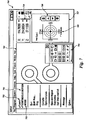
- FIGURE 7 is a sample screenshot from a video display that illustrates a user interface feature that allows a user to determine whether or not to implement part program creation according to the principles of this invention, in conjunction with learn mode part programming.
- a video display 700 includes a workpiece image display window 703, and a video tool panel 706, a motion control panel 707 including a Z-axis focus control portion 708 and an X-Y motion control portion 709, and an X-Y-Z position display panel 710.
- the video display 700 also includes a drop-down menu panel 701 that includes a "Learn" mode menu option 702, that can selected, for example by a user positioning a cursor over the menu option and clicking.
- the drop-down menu panel 701 also includes a "CONTINUOUS MOTION MODE" menu option 703, that can selected or not selected, for example by a user positioning a cursor over the menu option and clicking, in order to determine whether continuous motion part programming methods or routines according to this invention will be activated during learn mode part programming operations, as previously described herein.
- continuous motion part programming methods are to be activated during learn mode operations, this is indicated by the presence of a check mark next to the menu option.
- the systems and methods according to this invention can be activated or deactivated according to user input through the graphical user interface features described above.
- continuous motion part programming methods are not activated during learn mode operations, conventional part programming results are provided during learn mode operations.
- the user may use the same learn mode operation entry practices regardless of whether continuous motion part programming methods or conventional part programming methods are used, but the respectively resulting part programs will have a different arrangement of instructions, as previously described herein.
- continuous motion part programming methods are activated during all learn mode operations, and the menu option 703 may be omitted.
Landscapes
- Engineering & Computer Science (AREA)
- Quality & Reliability (AREA)
- Computer Vision & Pattern Recognition (AREA)
- Physics & Mathematics (AREA)
- General Physics & Mathematics (AREA)
- Theoretical Computer Science (AREA)
- Length Measuring Devices By Optical Means (AREA)
- Image Analysis (AREA)
Claims (7)
- Verfahren zum Programmieren eines Präzisionsmaschinenvisionsinspektionssystems zum Inspizieren eines Arbeitsstücks, wobei das Präzisisionsmaschinenvisionsinspektionssystem ein Bildaufnahmesystem umfasst, welches zumindest eine Kamera (260), einen Arbeitsstücktisch (32, 210) und einen Steuersystemabschnitt (120) umfasst, wobei zumindest eines von dem Arbeitsstücktisch (32, 210) und der Kamera (260) beweglich ist, um eine relative Bewegung zueinander zu ermöglichen, wobei das Verfahren umfasst:ein Benutzer betreibt das Präzisisionsmaschinenvisionsinspektionssystem während eines Lernmodus des Betriebs, um Lernmodusabläufe durchzuführen, die eine Vielzahl von Bildaufnahmeabläufen umfassen, die mit einer Vielzahl verbundener Analyseabläufe in einer Lernmodussequenz von Abläufen durchsetzt sind;Bestimmen, ob die jeweiligen Abläufe, die während des Lernmodus des Betriebs durchgeführt wurden, eines von a) und b) sind, wobeia) kompatible Abläufe, die Bildaufnahmeabläufe und damit verbundene Bildanalyseabläufe umfassen, die kompatibel mit einer Aufnahmesequenz von Abläufen für bewegliche Bilder sind, wobei die Abläufe eine Aufnahme einer Vielzahl von Bildern unter Verwendung kontinuierlich relativer Bewegung umfassen, undb) inkompatible Abläufe, die inkompatibel sind mit einer Aufnahmesequenz von Abläufen für bewegliche Bilder; und Teilprogramminstruktionen, die den Lernmodusabläufen entsprechen, wobei:kompatible Abläufe automatisch in die Teilprogramminstruktionen wieder eingeordnet werden, um eine Laufmodussequenz von Abläufen bereitzustellen, die sich von der Lernmodussequenz von Abläufen unterscheidet; unddas Wiedereinordnen der kompatiblen Abläufe ein Gruppieren kompatibler Bildaufnahmeabläufe einschließt, um eine Aufnahmesequenz für bewegliche Bilder bereitzustellen, die ein Aufnehmen und Speichern einer Vielzahl von Bildern unter Verwendung kontinuierlich relativer Bewegung und ein nachfolgendes Wiederaufrufen der gespeicherten Bilder aus der Vielzahl von Bildern und das Speichern der damit verbundenen Bildanalyseabläufe umfasst.
- Verfahren nach Anspruch 1, wobei der Schritt des Bestimmens, ob entsprechende Abläufe entweder kompatible Abläufe oder inkompatible Abläufe sind, automatisch ohne eine Benutzereingabe durchgeführt wird.
- Verfahren nach Anspruch 1, wobei das Bestimmen, ob entsprechende Abläufe, die während des Lernmodus des Betriebs ausgeführt werden, inkompatible Abläufe sind, ein Bestimmen umfassen, ob die entsprechenden Abläufe zumindest entweder von einer inkompatiblen Kategorie sind, oder Teil eines Satzes von Abläufen sind, die als inkompatibel mit einer Aufnahme beweglicher Bilder gemäß ihrem Typus vorherbestimmt sind, und die inkompatible Kategorie oder der vorherbestimmte inkompatible Typus zumindest eine einer Kategorie oder eines Typus eines Ablauf umfasst, welcher eine variable Bewegung beinhaltet, welcher in Abhängigkeit von dem Arbeitsstück variiert, welches inspiziert wird, einer Kategorie oder eines Typus eines Ablaufs, dessen Zeit für den Abschluss von den Leistungseigenschaften eines einzelnen Maschinenvisionssystems abhängt, eine Kategorie oder einen Typus von Ablauf, welcher Information benötigt, welche aus einer unmittelbaren Bildanalyse stammt, und eine Kategorie oder einen Typus eines Ablaufs, welcher ein Aufnehmen vieler Bilder an derselben Stelle auf dem Arbeitsstück beinhaltet.
- Verfahren nach Anspruch 1, wobei, wenn entsprechende Abläufe als inkompatible Abläufe vorbestimmt sind, das Verfahren ein Bereitstellen entsprechender jeweiliger Teilprogramminstruktionen umfasst, die automatisch angeordnet werden, um eine vorher eingerichtete Aufnahmesequenz von Abläufen für bewegliche Bilder zu unterbrechen.
- Verfahren nach Anspruch 5, wobei die Teilprogramminstruktionen auf einem Präzisisionsmaschinenvisionsinspektionssystem durchgeführt werden, wobei das Durchführen ein Aufnehmen und Speichern einer Vielzahl von Bildern unter Verwendung kontinuierlicher Bewegung umfasst, ein nachfolgendes Unterbrechen der kontinuierlichen Bewegung und ein Durchführen von Abläufen, welche ein Bild aufnehmen und das Bild analysieren, um ein Ergebnis bereitzustellen, welches von dem Bild abhängt, und ein darauf folgendes Wiederaufrufen der entsprechenden Bilder aus der Vielzahl von Bildern, die unter Verwendung einer kontinuierlichen Bewegung aufgenommen und gespeichert wurden, und ein Analysieren der wieder aufgerufenen entsprechenden Bilder auf Grundlage der vorher definierten jeweiligen Analyseabläufe.
- Ein computerlesbares Medium, umfassend computerausführbare Instruktionen, die in einen Steuersystemabschnitt (120) eines Präzisisionsmaschinenvisionsinspektionssystems geladen werden können, um ein Arbeitsstück zu inspizieren, wobei das Präzisisionsmaschinenvisionsinspektionssystem ein Bildaufnahmesystem umfasst, welches zumindest eine Kamera (260), einen Arbeitsstücktisch (32, 210) und den Steuersystemabschnitt (120) umfasst, wobei zumindest eines von dem Arbeitsstücktisch (32, 210) und der Kamera (260) beweglich ist, um eine relative Bewegung zueinander zu ermöglichen, wobei die computerausführbaren Instruktionen, wenn sie auf dem Steuersystemabschnitt (120) ausgeführt werden, die Schritte durchführen, die umfassen:Erhalten von Lernmodusabläufen, die eine Vielzahl von Bildaufnahmeabläufen umfassen, die unterbrochen sind durch eine Vielzahl von verbundenen Bildanalyseablaufeingaben durch einen Benutzer in einer Lernmodussequenz der Abläufe während eines Lernmodus des Betriebs des Präzisisionsmaschinenvisionsinspektionssystems;Bestimmen, ob entsprechende Abläufe der erhaltenen Ablaufeingaben durch den Benutzer eines von a) und b) sind,wobeia) kompatible Abläufe Bildaufnahmeabläufe und verbundene Bildanalyseabläufe umfassen, die mit einer Aufnahmesequenz von Abläufen für bewegliche Bilder kompatibel sind, welche ein Aufnehmen einer Vielzahl von Bildern unter Verwendung kontinuierlicher relativer Bewegung umfassen; undb) inkompatible Abläufe, die mit einer Aufnahmesequenz von Abläufen für bewegliche Bilder inkompatibel sind, undTeilprogramminstruktionen, die den Lernmodusabläufen entsprechen, wobei:kompatible Abläufe automatisch in die Teilprogramminstruktionen wieder eingeordnet werden, um eine Laufmodussequenz von Abläufen bereitzustellen, die sich von der Lernmodussequenz von Abläufen unterscheidet; unddas Wiedereinordnen der kompatiblen Abläufe schließt ein Gruppieren kompatibler Bildaufnahmeabläufe ein, um eine Aufnahmesequenz für bewegliche Bilder bereitzustellen, die ein Aufnehmen und Speichern einer Vielzahl von Bildern unter Verwendung einer kontinuierlichen relativen Bewegung umfasst, und ein nachfolgendes Wiederaufrufen der gespeicherten Bilder aus der Vielzahl von Bildern und ein Durchführen der verbundenen Bildanalyseabläufe.
- Verfahren nach irgendeinem der vorigen Ansprüche, wobei ein Satz von Abläufen als inkompatibel mit einer Aufnahme beweglicher Bilder gemäß ihrem Typus vorbestimmt wird.
Applications Claiming Priority (1)
| Application Number | Priority Date | Filing Date | Title |
|---|---|---|---|
| US11/018,155 US7590276B2 (en) | 2004-12-20 | 2004-12-20 | System and method for programming interrupting operations during moving image acquisition sequences in a vision system |
Publications (3)
| Publication Number | Publication Date |
|---|---|
| EP1679656A2 EP1679656A2 (de) | 2006-07-12 |
| EP1679656A3 EP1679656A3 (de) | 2010-05-26 |
| EP1679656B1 true EP1679656B1 (de) | 2012-03-14 |
Family
ID=36446818
Family Applications (1)
| Application Number | Title | Priority Date | Filing Date |
|---|---|---|---|
| EP05021845A Expired - Lifetime EP1679656B1 (de) | 2004-12-20 | 2005-10-06 | System und Verfahren zur Programmierung von unterbrechenden Operationen während der Erfassungs von Sequenzen von sich bewegenden Bildern |
Country Status (3)
| Country | Link |
|---|---|
| US (1) | US7590276B2 (de) |
| EP (1) | EP1679656B1 (de) |
| CN (1) | CN1805542B (de) |
Families Citing this family (28)
| Publication number | Priority date | Publication date | Assignee | Title |
|---|---|---|---|---|
| GB2428927A (en) * | 2005-08-05 | 2007-02-07 | Hewlett Packard Development Co | Accurate positioning of a time lapse camera |
| US7636466B2 (en) * | 2006-01-11 | 2009-12-22 | Orbotech Ltd | System and method for inspecting workpieces having microscopic features |
| US7652716B2 (en) * | 2007-05-31 | 2010-01-26 | Microsoft Corporation | Computer-controlled lighting for video communication |
| US8923602B2 (en) * | 2008-07-22 | 2014-12-30 | Comau, Inc. | Automated guidance and recognition system and method of the same |
| CN101769475B (zh) * | 2008-12-31 | 2013-04-24 | 鸿富锦精密工业(深圳)有限公司 | 影像测量仪光源及利用该光源的自动定位系统 |
| CN101782369B (zh) * | 2009-01-16 | 2012-09-19 | 鸿富锦精密工业(深圳)有限公司 | 影像量测对焦系统及方法 |
| TWI411862B (zh) * | 2009-02-27 | 2013-10-11 | Hon Hai Prec Ind Co Ltd | 影像量測對焦系統及方法 |
| TWI417517B (zh) * | 2009-02-27 | 2013-12-01 | Hon Hai Prec Ind Co Ltd | 影像測量儀光源及利用該光源的自動定位系統 |
| JP5547105B2 (ja) * | 2011-02-01 | 2014-07-09 | 株式会社キーエンス | 寸法測定装置、寸法測定方法及び寸法測定装置用のプログラム |
| JP5679560B2 (ja) * | 2011-02-01 | 2015-03-04 | 株式会社キーエンス | 寸法測定装置、寸法測定方法及び寸法測定装置用のプログラム |
| US9167215B2 (en) | 2011-11-15 | 2015-10-20 | Mitutoyo Corporation | Machine vision system editing environment for a part program in which a continuous stream of image acquisition operations are performed during a run mode |
| US9223306B2 (en) | 2011-11-15 | 2015-12-29 | Mitutoyo Corporation | System and method utilizing an editing initialization block in a part program editing environment in a machine vision system |
| US9013574B2 (en) | 2011-11-15 | 2015-04-21 | Mitutoyo Corporation | Machine vision system program editing environment including synchronized user interface features |
| US8957960B2 (en) * | 2011-11-15 | 2015-02-17 | Mitutoyo Corporation | Machine vision system program editing environment including real time context generation features |
| US8902307B2 (en) | 2011-11-15 | 2014-12-02 | Mitutoyo Corporation | Machine vision system editing environment for a part program in which a continuous stream of image acquisition operations are performed during a run mode |
| US20140012511A1 (en) * | 2012-07-09 | 2014-01-09 | Dexcom, Inc. | Systems and methods for leveraging smartphone features in continuous glucose monitoring |
| US9733902B2 (en) | 2013-05-13 | 2017-08-15 | Mitutoyo Corporation | Machine vision system program editing environment including operating context aware copy and paste feature |
| WO2015097893A1 (ja) * | 2013-12-27 | 2015-07-02 | 株式会社牧野フライス製作所 | 工作機械の制御装置 |
| DE102015208337A1 (de) | 2014-06-17 | 2015-12-17 | Mitutoyo Corp. | Bearbeitungsumgebung eines maschinellen sichtsystems für ein teileprogramm, in dem ein durchgehender datenstrom von bilderfassungsvorgängen in einem laufmodus ausgeführt wird |
| GB2543778B (en) * | 2015-10-27 | 2018-08-08 | Imagination Tech Ltd | Systems and methods for processing images of objects |
| GB2543779B (en) * | 2015-10-27 | 2018-07-25 | Imagination Tech Ltd | Systems and methods for processing images of objects |
| GB2543777B (en) * | 2015-10-27 | 2018-07-25 | Imagination Tech Ltd | Systems and methods for processing images of objects |
| US10682729B2 (en) | 2015-12-01 | 2020-06-16 | General Electric Company | System for automated in-process inspection of welds |
| JP6858878B2 (ja) * | 2017-02-28 | 2021-04-14 | クオリティー ヴィジョン インターナショナル インコーポレイテッドQuality Vision International, Inc. | 3dモデルの試験対象物への自動アライメント |
| JP7028333B2 (ja) * | 2018-03-05 | 2022-03-02 | オムロン株式会社 | 照明条件の設定方法、装置、システム及びプログラム並びに記憶媒体 |
| US20220292665A1 (en) * | 2019-10-02 | 2022-09-15 | Konica Minolta, Inc. | Workpiece surface defect detection device and detection method, workpiece surface inspection system, and program |
| US20230196840A1 (en) * | 2020-03-24 | 2023-06-22 | Sony Group Corporation | Work management device and work state determination method |
| CN117243642B (zh) * | 2023-11-16 | 2024-01-26 | 山东皇圣堂药业有限公司 | 一种基于机器视觉的智能咽拭子采样设备控制系统 |
Family Cites Families (8)
| Publication number | Priority date | Publication date | Assignee | Title |
|---|---|---|---|---|
| US4305130A (en) * | 1979-05-29 | 1981-12-08 | University Of Rhode Island | Apparatus and method to enable a robot with vision to acquire, orient and transport workpieces |
| US6408429B1 (en) * | 1997-01-17 | 2002-06-18 | Cognex Corporation | Machine vision system for identifying and assessing features of an article |
| US6987867B1 (en) * | 1997-09-15 | 2006-01-17 | Uster Technologies Ag | Process for evaluating data from textile fabrics |
| US6324298B1 (en) * | 1998-07-15 | 2001-11-27 | August Technology Corp. | Automated wafer defect inspection system and a process of performing such inspection |
| US6404910B1 (en) * | 1998-12-31 | 2002-06-11 | Kimberly-Clark Worldwide, Inc. | Making absorbent articles using vision imaging system |
| US6542180B1 (en) | 2000-01-07 | 2003-04-01 | Mitutoyo Corporation | Systems and methods for adjusting lighting of a part based on a plurality of selected regions of an image of the part |
| US6916221B2 (en) * | 2002-11-18 | 2005-07-12 | Eastman Kodak Company | Determining defects in OLED devices |
| US7030351B2 (en) * | 2003-11-24 | 2006-04-18 | Mitutoyo Corporation | Systems and methods for rapidly automatically focusing a machine vision inspection system |
-
2004
- 2004-12-20 US US11/018,155 patent/US7590276B2/en active Active
-
2005
- 2005-10-06 EP EP05021845A patent/EP1679656B1/de not_active Expired - Lifetime
- 2005-12-01 CN CN200510127288.XA patent/CN1805542B/zh not_active Expired - Lifetime
Also Published As
| Publication number | Publication date |
|---|---|
| EP1679656A3 (de) | 2010-05-26 |
| US20060133663A1 (en) | 2006-06-22 |
| EP1679656A2 (de) | 2006-07-12 |
| CN1805542B (zh) | 2010-12-22 |
| US7590276B2 (en) | 2009-09-15 |
| CN1805542A (zh) | 2006-07-19 |
Similar Documents
| Publication | Publication Date | Title |
|---|---|---|
| EP1679656B1 (de) | System und Verfahren zur Programmierung von unterbrechenden Operationen während der Erfassungs von Sequenzen von sich bewegenden Bildern | |
| US7499584B2 (en) | Smear-limit based system and method for controlling vision systems for consistently accurate and high-speed inspection | |
| US8902307B2 (en) | Machine vision system editing environment for a part program in which a continuous stream of image acquisition operations are performed during a run mode | |
| US7627162B2 (en) | Enhanced video metrology tool | |
| JP5570945B2 (ja) | 正確な寸法検査用の自動焦点ビデオツールおよび方法 | |
| US7394926B2 (en) | Magnified machine vision user interface | |
| JP6239232B2 (ja) | 高性能エッジフォーカスツール | |
| US7636478B2 (en) | Fast multiple template matching using a shared correlation map | |
| JP6071452B2 (ja) | マシンビジョンシステムのパートプログラム編集環境内で編集初期化ブロックを利用するシステム及び方法 | |
| JP5972563B2 (ja) | 構造化照明を用いるエッジ検出 | |
| US20040223053A1 (en) | Machine vision inspection system and method having improved operations for increased precision inspection throughput | |
| US9167215B2 (en) | Machine vision system editing environment for a part program in which a continuous stream of image acquisition operations are performed during a run mode | |
| JP2014022662A (ja) | ウエハ外観検査装置及びウエハ外観検査装置における感度しきい値設定方法 | |
| JP2009523244A (ja) | 微細な特徴を有するワークを検査する為のシステムおよび方法 | |
| CN105204840B (zh) | 用于部件程序的机器视觉系统的编辑环境 |
Legal Events
| Date | Code | Title | Description |
|---|---|---|---|
| PUAI | Public reference made under article 153(3) epc to a published international application that has entered the european phase |
Free format text: ORIGINAL CODE: 0009012 |
|
| AK | Designated contracting states |
Kind code of ref document: A2 Designated state(s): AT BE BG CH CY CZ DE DK EE ES FI FR GB GR HU IE IS IT LI LT LU LV MC NL PL PT RO SE SI SK TR |
|
| AX | Request for extension of the european patent |
Extension state: AL BA HR MK YU |
|
| PUAL | Search report despatched |
Free format text: ORIGINAL CODE: 0009013 |
|
| AK | Designated contracting states |
Kind code of ref document: A3 Designated state(s): AT BE BG CH CY CZ DE DK EE ES FI FR GB GR HU IE IS IT LI LT LU LV MC NL PL PT RO SE SI SK TR |
|
| AX | Request for extension of the european patent |
Extension state: AL BA HR MK YU |
|
| 17P | Request for examination filed |
Effective date: 20101122 |
|
| 17Q | First examination report despatched |
Effective date: 20101229 |
|
| AKX | Designation fees paid |
Designated state(s): DE FR GB |
|
| RIC1 | Information provided on ipc code assigned before grant |
Ipc: G06T 7/00 20060101AFI20110802BHEP |
|
| GRAP | Despatch of communication of intention to grant a patent |
Free format text: ORIGINAL CODE: EPIDOSNIGR1 |
|
| GRAS | Grant fee paid |
Free format text: ORIGINAL CODE: EPIDOSNIGR3 |
|
| GRAA | (expected) grant |
Free format text: ORIGINAL CODE: 0009210 |
|
| RTI1 | Title (correction) |
Free format text: SYSTEM AND METHOD FOR PROGRAMMING INTERRUPTING OPERATIONS DURING MOVING IMAGE ACQUISITION SEQUENCES |
|
| AK | Designated contracting states |
Kind code of ref document: B1 Designated state(s): DE FR GB |
|
| REG | Reference to a national code |
Ref country code: GB Ref legal event code: FG4D |
|
| REG | Reference to a national code |
Ref country code: DE Ref legal event code: R096 Ref document number: 602005033110 Country of ref document: DE Effective date: 20120510 |
|
| PLBE | No opposition filed within time limit |
Free format text: ORIGINAL CODE: 0009261 |
|
| STAA | Information on the status of an ep patent application or granted ep patent |
Free format text: STATUS: NO OPPOSITION FILED WITHIN TIME LIMIT |
|
| 26N | No opposition filed |
Effective date: 20121217 |
|
| REG | Reference to a national code |
Ref country code: DE Ref legal event code: R097 Ref document number: 602005033110 Country of ref document: DE Effective date: 20121217 |
|
| REG | Reference to a national code |
Ref country code: FR Ref legal event code: PLFP Year of fee payment: 11 |
|
| REG | Reference to a national code |
Ref country code: FR Ref legal event code: PLFP Year of fee payment: 12 |
|
| REG | Reference to a national code |
Ref country code: FR Ref legal event code: PLFP Year of fee payment: 13 |
|
| REG | Reference to a national code |
Ref country code: FR Ref legal event code: PLFP Year of fee payment: 14 |
|
| PGFP | Annual fee paid to national office [announced via postgrant information from national office to epo] |
Ref country code: FR Payment date: 20191028 Year of fee payment: 15 |
|
| PG25 | Lapsed in a contracting state [announced via postgrant information from national office to epo] |
Ref country code: FR Free format text: LAPSE BECAUSE OF NON-PAYMENT OF DUE FEES Effective date: 20201031 |
|
| PGFP | Annual fee paid to national office [announced via postgrant information from national office to epo] |
Ref country code: DE Payment date: 20241021 Year of fee payment: 20 |
|
| PGFP | Annual fee paid to national office [announced via postgrant information from national office to epo] |
Ref country code: GB Payment date: 20241022 Year of fee payment: 20 |
|
| REG | Reference to a national code |
Ref country code: DE Ref legal event code: R071 Ref document number: 602005033110 Country of ref document: DE |
|
| REG | Reference to a national code |
Ref country code: GB Ref legal event code: PE20 Expiry date: 20251005 |