EP1679536A1 - Lens barrel - Google Patents
Lens barrel Download PDFInfo
- Publication number
- EP1679536A1 EP1679536A1 EP04773664A EP04773664A EP1679536A1 EP 1679536 A1 EP1679536 A1 EP 1679536A1 EP 04773664 A EP04773664 A EP 04773664A EP 04773664 A EP04773664 A EP 04773664A EP 1679536 A1 EP1679536 A1 EP 1679536A1
- Authority
- EP
- European Patent Office
- Prior art keywords
- lens barrel
- shaft
- lens
- rotation
- optical axis
- Prior art date
- Legal status (The legal status is an assumption and is not a legal conclusion. Google has not performed a legal analysis and makes no representation as to the accuracy of the status listed.)
- Withdrawn
Links
Images

Classifications
-
- G—PHYSICS
- G02—OPTICS
- G02B—OPTICAL ELEMENTS, SYSTEMS OR APPARATUS
- G02B7/00—Mountings, adjusting means, or light-tight connections, for optical elements
- G02B7/02—Mountings, adjusting means, or light-tight connections, for optical elements for lenses
- G02B7/04—Mountings, adjusting means, or light-tight connections, for optical elements for lenses with mechanism for focusing or varying magnification
- G02B7/10—Mountings, adjusting means, or light-tight connections, for optical elements for lenses with mechanism for focusing or varying magnification by relative axial movement of several lenses, e.g. of varifocal objective lens
- G02B7/102—Mountings, adjusting means, or light-tight connections, for optical elements for lenses with mechanism for focusing or varying magnification by relative axial movement of several lenses, e.g. of varifocal objective lens controlled by a microcomputer
Definitions
- the lens barrel includes: a cylindrical-shaped body tube for housing an inner lens mechanism; a first movable member for holding a first movable lens, moving to an optical axis direction by guiding first positioning shafts respectively extending approximately parallel to the optical axis direction, and being restricted its rotation with a first rotation-restricting shaft; a second movable member disposed along with the first movable lens in the optical axis direction, for holding the second movable lens, moving to the optical axis direction by guiding second positioning shafts respectively extending approximately parallel to the optical axis direction, and being restricted its rotation with a second rotation-restricting shaft.
- the lens barrel characterized in that the first positioning shaft and the second rotation-restricting shaft are integrally formed to constitute a common guiding shaft extending across the lens barrel in the optical axis direction, one end of the first rotation-restricting shaft is fixed to a holding section provided in a middle portion of the lens barrel, and a predetermined space is formed in an extended line of the first rotation-restricting shaft.
- the fourth lens group 40 (a second movable lens) is a focus lens for focusing and fitted and held by a ring-shaped second movable lens frame 41 to constitute a focus movable member 42 (a second movable member).
- a cylindrical-shaped sleeve section 41a extending frontwardly and for inserting the guiding shaft 62
- a flange section 41b projected outwardly at a position shifted by 180-degree from a position of the sleeve section 41a, centered the optical axis, and having a guiding hole at the center thereof for inserting the guiding shaft 61.
- the guiding shaft 61 is served as a common guiding shaft, it is possible to reduce the number of shafts.
- the guiding shaft 63 is formed only within the moving range of the zoom movable member 22, the coil unit 70 is disposed in the space positioned behind the guiding shaft 63, hence the whole lens barrel can be made compact.
- the lens barrel of the present invention is not limited to a digital still camera, and can be applied to optical equipment, for example, an imaging device such as other camera or an observation device such as a magnifying lens.
Landscapes
- Physics & Mathematics (AREA)
- Engineering & Computer Science (AREA)
- General Engineering & Computer Science (AREA)
- General Physics & Mathematics (AREA)
- Optics & Photonics (AREA)
- Lens Barrels (AREA)
Abstract
Description
- The present invention relates to a lens barrel having a forward/backward mechanism of a lens in an optical axis direction.
- In recent years, in response to the demands for miniaturization of a zoom lens used in video cameras and digital still cameras, there has been proposed a technique of using a guiding shaft provided for movement of two movable members (for zooming and focusing) in common, and the technique has been practically used.
- As such a technique, two guiding shafts are generally prepared for each movable member, and one of the shafts is used as a positioning shaft for positioning and the other shaft is used as a rotation-restricting shaft for correcting direction. When these two guiding shafts are independently provided, four guiding shafts are needed to operate two movable members. However, in order to miniaturize a lens unit, it has been practice to make the guiding shafts to be used in common (for example, refer to Japanese Patent Application Publication No. HEI8-149777).
- In this technique, by using each guiding shaft in common, two movable members can be held by two guiding shafts. In this case, it is required to consider a holding mechanism so that movement areas of respective movable members do not overlap each other. In general, when a lens barrel is designed so as not to overlap the movement areas, the lens barrel becomes longer in an optical axis direction. In addition, if a guiding shaft is a positioning shaft for making a movable member to move in the optical axis direction, the positioning shaft is usually held at two points of the both ends of the guiding shaft. In this case, the lager a distance between the two points is, the more the movable member operates stably.
- However, when the guiding shaft is actuallyused in common, a distance between two points for holding the positioning shaft is restricted and as a result, the stable operation of the movable member is disturbed. In addition, because the positioning shaft is generally required to guide with higher precision than the rotation-restricting shaft due to amechanic reason, the most favorable case is that the positioning shafts for positioning are used in common and the rotation-restricting shafts are used in common, ideally. However, because of the above-mentioned reason, this arrangement may become causes of troubles and factors for increasing the size of outer shape of the lens barrel.
- The present invention is made in view of the above-mentioned circumstances, and is to provide a lens barrel which has a compact inner lens mechanism and is able to be manufactured in a small size at low cost.
- In order to solve the above-mentioned problem, the present invention provides a lens barrel. The lens barrel includes: a cylindrical-shaped body tube for housing an inner lens mechanism; a first movable member for holding a first movable lens, moving to an optical axis direction by guiding first positioning shafts respectively extending approximately parallel to the optical axis direction, and being restricted its rotation with a first rotation-restricting shaft; a second movable member disposed along with the first movable lens in the optical axis direction, for holding the second movable lens, moving to the optical axis direction by guiding second positioning shafts respectively extending approximately parallel to the optical axis direction, and being restricted its rotation with a second rotation-restricting shaft. The lens barrel characterized in that the first positioning shaft and the second rotation-restricting shaft are integrally formed to constitute a common guiding shaft extending across the lens barrel in the optical axis direction, one end of the first rotation-restricting shaft is fixed to a holding section provided in a middle portion of the lens barrel, and a predetermined space is formed in an extended line of the first rotation-restricting shaft.
- It is to be noted that the terms "inner lens mechanism" as used herein means that a mechanism including every lens, every movable member, every positioning shaft, every rotation-restricting shaft and other mechanism to be disposed in the lens barrel.
- According to the lens barrel, since the first positioning shaft and the second rotation-restricting shaft are formed to be a common guiding shaft, the number of guiding shafts can be reduced. In this case, since the first positioning shaft and the second positioning shaft are configured separately, sliding lengths for each movable member can be sufficiently obtained with respect to each positioning shaft. Accordingly, the above-mentioned distance between two points can have a sufficient length, and in a case where a sleeve section for sliding along each positioning shaft is provided on each movable member, it is possible to have a sufficient length for the sleeve section.
- In addition, with the result of fixing the one end of the first rotation-restricting shaft at the holding section provided in the middle portion of the lens barrel, a predetermined space is formed in the extended line of the first rotation-restricting shaft, and other inner lens mechanism can be arranged in the space.
- According to such lens barrel of the present invention, the number of shafts can be reduced by having a common guiding shaft, and also a predetermined space is formed because the first rotation-restricting shaft is shortened, and thus it is possible to realize for saving space within the lens barrel. As the result, a material cost involved with shafts can be cut down and other inner lens mechanism can be arranged in the space, so that the whole lens barrel can be made compact.
- Furthermore, a sufficient sliding length of eachmovable member with respect to each positioning shaft can be obtained, and therefore, the lens barrel can realize stable operations of respective movable member with high precision, even in a compact size.
-
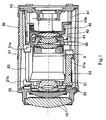
- Fig. 1 is a cross-sectional view of a lens barrel according to an embodiment of the present invention.
- Fig. 2 is a perspective view showing an inner main portion of a lens barrel.
- In the following, an embodiment of the present invention will be described in detail with reference to drawings. In the present embodiment, the present invention is applied to a lens barrel of a digital still camera. Fig. 1 is a cross-sectional view of the lens barrel of the present embodiment and Fig. 2 is a perspective view showing an inner main portion of the lens barrel. It is noted that, in the following description, it ought to express that the left side in the drawings is the front side and the right side in the drawings is the rear side, with reference to an optical axis direction (a dashed line in the drawings) in Fig. 1, for simplicity of explanation.
- As shown in Fig. 1, the lens barrel of the present embodiment is configured to have inner lens mechanisms such as a
first lens group 10, asecond lens group 20, aniris 5, athird lens group 30, and afourth lens group 40, which are disposed in this order from the front, in a cylindrical-shaped lens barrel 50. - The
lens barrel 50 is configured with amiddle lens barrel 51 constituting a main body, afront lens barrel 52 holding thefirst lens group 10 in an inner diameter direction and attached at the front end of themiddle lens barrel 51 to close it, and arear lens barrel 53 holding a CCD in an inner diameter direction and attached at the rear end of themiddle lens barrel 51 to close it. - In addition, as shown in Fig, 2, three
guiding shafts lens barrel 50. Of these shafts, as for the guidingshafts front lens barrel 52 and other ends are fixed to therear lens barrel 53. On the other hand, as for the guidingshaft 63, one end thereof is fixed to thefront lens barrel 52 and the other end is fixed to aholding section 51a which is provided in a middle portion of themiddle lens barrel 51 so as to be slightly inwardly extended (refer to Fig. 1). - The second lens group 20 (a first movable lens) is a zoom lens for zooming and fitted and held by a ring-shaped first
movable lens frame 21 to constitute a zoom movable member 22 (a first movable member). On the outer circumference portion of the firstmovable lens frame 21, there are provided a cylindrical-shaped sleeve section 21a extending rearwardly and for inserting the guidingshaft 61, and aflange section 21b projected outwardly at a position shifted by 180-degree from a position of thesleeve section 21a, centered the optical axis, and having a guiding hole at the center thereof for inserting the guidingshaft 63. Amovement of thezoommovable member 22 to the optical direction is guided by engaging thesleeve section 21a with the guidingshaft 61 and a rotation thereof centering around the guidingshaft 61 is restricted by engaging theflange section 21b with the guidingshaft 63. In the present embodiment, the guidingshaft 61 corresponds to a first positioning shaft and the guidingshaft 63 corresponds to a first rotation-restricting shaft. - The fourth lens group 40 (a second movable lens) is a focus lens for focusing and fitted and held by a ring-shaped second
movable lens frame 41 to constitute a focus movable member 42 (a second movable member). On the outer circumference of the secondmovable lens frame 41, there are provided a cylindrical-shaped sleeve section 41a extending frontwardly and for inserting the guidingshaft 62 , and aflange section 41b projected outwardly at a position shifted by 180-degree from a position of thesleeve section 41a, centered the optical axis, and having a guiding hole at the center thereof for inserting the guidingshaft 61. A movement of the focusmovable member 42 to the optical axis direction is guided by engaging thesleeve section 41a with the guidingshaft 62 and a rotation thereof centering around the guidingshaft 62 is restricted by engaging theflange section 41b with the guidingshaft 61. In the present embodiment, the guidingshaft 62 corresponds to a second positioning shaft. In addition, the guidingshaft 61 corresponds also to a second rotation-restricting shaft, whichmeans that the guidingshaft 61 constitutes a guiding shaft common with the first positioning shaft. - It is to be noted that because the focus lens is required to move with higher precision than the zoom lens, the
sleeve section 41a of the focusmovable member 42 is made longer than thesleeve section 21a of the zoommovable member 22 in the present embodiment. In addition, when the focusmovable member 42 is moved to the front end, the front end of thesleeve section 41a is made to come close to thefront lens barrel 52, and when the focusmovable member 42 moves to the rear end, the end of thesleeve section 41a is made to come close to therear lens barrel 53. Accordingly, a distance between thefront lens barrel 52 and therear lens barrel 53 is reduced within a range enabling the focusmovable member 42 to move, and therefore the whole lens barrel is configured compact. - In a space formed at a rear portion in an extended line of the guiding shaft, there is disposed a
coil unit 70 of a linear motor which constitutes a driving section for moving the focusmovable member 42 to the optical axis direction. Thecoil unit 70 is configured with a flat coil structure including adriving coil 71, amagnet 72 and a yoke which is not shown, and disposed to be housed in thelens barrel 50. It is to be noted that the zoommovable member 22 is configured to move to the optical axis direction by a stepping motor which is not shown. In the present embodiment, as lubrication of these motors such as the liner motor to drive the focusmovable member 42 and the stepping motor to drive the zoommovable member 22, different greases are respectively used. However because the positioning shafts (guidingshafts 61 and 62) of the each movable member are separately configured, it is unnecessary to apply separately the greases depending on portions of each positioning shaft. - Returning to the Fig. 1, the iris 5 (aperture unit) is disposed at the front of the
third lens group 30 composed of fixed lenses which is disposed between thesecond lens group 20 and thefourth lens group 40. - In addition, the lens barrel of the present embodiment has a centering mechanism capable of adjusting a tilt with respect to the optical axis, on the
front lens barrel 52. - Specifically, eccentric pins not shown are put around the side surface of the
front lens barrel 52 so as to have a space equally from each other. By making the each eccentric pin to rotate around its axis, a screw mechanism not shown can move a portion of thefront lens barrel 52 where the eccentric pins put around, to a direction of approaching to or separating from (frontward or backward direction) themiddle lens barrel 51 by a predetermined amount. As the result of moving thefront lens barrel 52 and tilting thefront lens barrel 52 with respect to themiddle lens barrel 51, thefirst lens group 10 can be centered. In addition, at this time, since each one end of the guidingshaft front lens barrel 52, tilts of these guiding shafts can be adjusted at the same time. Further, at this time, one end of the guidingshaft 63 is fixed at thefront lens barrel 52 and the other side thereof is fixed at the middle portion of themiddle lens barrel 51, and there is a distance between the zoommovable member 22 and the focusmovable member 42, whereby moving amounts of each movable member are slightly different and then they act differently from each other. Therefore, with use of their different movements, it is possible to perform high precision centering. - As described above, according to the lens barrel in the present embodiment, since the guiding
shaft 61 is served as a common guiding shaft, it is possible to reduce the number of shafts. In addition, the guidingshaft 63 is formed only within the moving range of the zoommovable member 22, thecoil unit 70 is disposed in the space positioned behind the guidingshaft 63, hence the whole lens barrel can be made compact. - On the other hand, since the guiding shaft 61 (the first positioning shaft) and the guiding shaft 62 (the second positioning shaft) are formed separately, the
sleeve section 21a of the zoommovable member 22 and thesleeve section 41a of the focusmovable member 42 can be made to have sufficient lengths, and a sliding length for the each movable member can also be sufficiently obtained. Accordingly, even having a compact size, the lens barrel can realize stable operations of each movable member with high precision. - As described above, the preferred embodiment of the present invention has been described, however the present invention is not limited to the specific embodiment and it will be obvious that various changes and modifications may be made without departing from the scope of the invention.
- For example, in the above embodiment, although it is shown the structure in which the centering mechanism is provided in the
front lens barrel 52, a similar centering mechanism may be provided in therear lens barrel 53 side or may be provided in both of thefront lens barrel 52 and therear lens barrel 53. - It is noted that in a case where the centering mechanism is provided in the
rear lens barrel 53, the rotation of the eccentric pin causes therear lens barrel 53 to move so as to tilt with respect to themiddle lens barrel 51, thereby the guidingshafts shaft 63 is not directly influenced by this movement because the guidingshaft 63 is not fixed to therear lens barrel 53. For that reason, it is caused a movement which causes moving amounts of the zoommovable member 22 and the focusmovable member 42 different from the case in the above embodiment. Accordingly, it is possible to perform further fine adjustment in centering with use of the difference of the movements. - In addition, in the above embodiment, the case is shown where the zoom lens constitutes the first movable lens and the focus lens constitutes the second movable lens, however, in accordance with a structure of an inner mechanism of a lens barrel, other lenses may be used as each movable lens.
- Further, the lens barrel of the present invention is not limited to a digital still camera, and can be applied to optical equipment, for example, an imaging device such as other camera or an observation device such as a magnifying lens.
- The present invention can be applied to optical equipment having a lens barrel which drives a plurality of movable members holding lenses and disposed in single file in an optical axis direction, along with a guiding shaft in a body tube.
Claims (9)
- A lens barrel comprising:a cylindrical-shaped body tube for housing an inner lens mechanism;a first movable member for holding a first movable lens, moving to an optical axis direction by guiding a first positioning shaft, and being restricted rotation thereof by a first rotation-restricting shaft respectively extending approximately parallel to the optical axis direction;a second movable member disposed along with the first movable lens in the optical axis direction, forholdinga second movable lens, moving to the optical axis direction by guiding a second positioning shaft, and being restricted rotation thereof by a second rotation restriction shaft respectively extending approximately parallel to the optical axis direction,the lens barrel characterized in that:the first positioning shaft and the second rotation-restricting shaft are integrally formed to constitute a common guiding shaft extending approximately between both ends of the lens barrel in the optical axis direction; one end of the first rotation-restricting shaft is fixed to a holding section provided in a middle portion of the lens barrel; and a predetermined space is formed in line with an axis of the first rotation-restricting shaft.
- The lens barrel according to claim 1, characterized in that
a coil unit of a linear motor constituting a driving section for moving the second movable member is disposed in the predetermined space. - The lens barrel according to claim 2, characterized in that
the driving section has a flat coil structure and a plurality of constituent elements thereof is disposed so as to be housed in the lens barrel. - The lens barrel according to claim 1, characterized in that
the first movable lens is a zoom lens and the second movable lens is a focus lens. - The lens barrel according to claim 4, characterized in that:lubrication greases for a driving actuator of the first movable lens and for a driving actuator of the second movable lens are different from each other; andon the first positioning shaft and on the second positioning shaft, grease is not changed depending on a portion tobeapplied, and one kind of grease is applied to the respective shafts to drive the respective driving actuators.
- The lens barrel according to claim 4, characterized in that:the tube bodyhas a cylindrical-shapedmiddle lens barrel, a front lens barrel and a rear lens barrel for closing openings at the both ends of the middle lens barrel, respectively; andone end of the first rotation-restricting shaft is held by the front lens barrel and the other end is held at the middle portion of the middle lens barrel.
- The lens barrel according to claim 1, characterized in that:the tube body has a cylindrical-shapedmiddle lens barrel, a front lens barrel and a rear lens barrel for closing openings at the both ends of the middle lens barrel, respectively;one end of the first rotation-restricting shaft is held by the front lens barrel and the other end is held at the middle portion of the middle lens barrel; andrespective one ends of the first positioning shaft and the second positioning shaft are held by the front lens barrel and the other ends are held by the rear lens barrel.
- The lens barrel according to claim 7, characterized in that:the front lens barrel has a centering mechanism capable of adjusting a tilt with respect to an optical axis; andthe centering mechanism centers the each positioning shaft and the each rotation-restricting shaft to have tilts, respectively.
- The lens barrel according to claim 7, characterized in that:the rear lens barrel has a centering mechanism capable of adjusting a tilt with respect to an optical axis; andthe centering mechanism centers the each positioning shaft is configured to have a tilt, respectively.
Applications Claiming Priority (2)
| Application Number | Priority Date | Filing Date | Title |
|---|---|---|---|
| JP2003344838A JP4487531B2 (en) | 2003-10-02 | 2003-10-02 | Lens barrel |
| PCT/JP2004/014803 WO2005033761A1 (en) | 2003-10-02 | 2004-09-30 | Lens barrel |
Publications (2)
| Publication Number | Publication Date |
|---|---|
| EP1679536A1 true EP1679536A1 (en) | 2006-07-12 |
| EP1679536A4 EP1679536A4 (en) | 2012-02-22 |
Family
ID=34419399
Family Applications (1)
| Application Number | Title | Priority Date | Filing Date |
|---|---|---|---|
| EP04773664A Withdrawn EP1679536A4 (en) | 2003-10-02 | 2004-09-30 | BARREL |
Country Status (6)
| Country | Link |
|---|---|
| US (1) | US7345835B2 (en) |
| EP (1) | EP1679536A4 (en) |
| JP (1) | JP4487531B2 (en) |
| KR (1) | KR20060069467A (en) |
| CN (1) | CN100541254C (en) |
| WO (1) | WO2005033761A1 (en) |
Families Citing this family (7)
| Publication number | Priority date | Publication date | Assignee | Title |
|---|---|---|---|---|
| JP2006350252A (en) * | 2005-06-20 | 2006-12-28 | Canon Inc | Imaging device and tilt device |
| CN101288012B (en) * | 2005-10-18 | 2011-01-19 | 夏普株式会社 | Lens unit and lens drive device |
| EP2690476A4 (en) * | 2011-03-24 | 2014-11-05 | Fujifilm Corp | Lens device |
| CN102736208B (en) * | 2011-03-31 | 2014-09-10 | 亚洲光学股份有限公司 | lens module |
| CN103293628A (en) * | 2012-03-01 | 2013-09-11 | 华晶科技股份有限公司 | Zooming and focusing mechanism and image capturing device thereof |
| CN110764232A (en) * | 2019-11-29 | 2020-02-07 | Oppo广东移动通信有限公司 | Optical Lenses and Electronics |
| CN114553987B (en) * | 2020-11-26 | 2025-02-21 | 华为技术有限公司 | Camera module, motor structure, and electronic equipment |
Family Cites Families (10)
| Publication number | Priority date | Publication date | Assignee | Title |
|---|---|---|---|---|
| JP3120886B2 (en) * | 1992-01-13 | 2000-12-25 | 富士写真光機株式会社 | Method of assembling zoom lens device |
| JPH06174998A (en) | 1992-12-02 | 1994-06-24 | Canon Inc | Lens barrel |
| JP3246241B2 (en) * | 1994-11-17 | 2002-01-15 | キヤノン株式会社 | Optical device |
| JPH08248293A (en) | 1995-03-09 | 1996-09-27 | Sony Corp | Lens barrel |
| US5748394A (en) * | 1995-07-26 | 1998-05-05 | Konica Corporation | Lens driving device |
| JP3641333B2 (en) * | 1996-11-29 | 2005-04-20 | ペンタックス株式会社 | Zoom lens and camera having zoom lens |
| JP2000019375A (en) * | 1998-07-02 | 2000-01-21 | Minolta Co Ltd | Driving device |
| JP4144943B2 (en) * | 1998-08-24 | 2008-09-03 | オリンパス株式会社 | Aperture device |
| JP2000137156A (en) * | 1998-11-04 | 2000-05-16 | Sony Corp | Lens drive |
| JP2001318298A (en) * | 2000-05-10 | 2001-11-16 | Asahi Optical Co Ltd | Optical device moving mechanism |
-
2003
- 2003-10-02 JP JP2003344838A patent/JP4487531B2/en not_active Expired - Fee Related
-
2004
- 2004-09-30 KR KR1020067003645A patent/KR20060069467A/en not_active Abandoned
- 2004-09-30 EP EP04773664A patent/EP1679536A4/en not_active Withdrawn
- 2004-09-30 US US10/570,703 patent/US7345835B2/en not_active Expired - Fee Related
- 2004-09-30 WO PCT/JP2004/014803 patent/WO2005033761A1/en not_active Ceased
- 2004-09-30 CN CNB2004800286501A patent/CN100541254C/en not_active Expired - Fee Related
Also Published As
| Publication number | Publication date |
|---|---|
| US20060285232A1 (en) | 2006-12-21 |
| CN100541254C (en) | 2009-09-16 |
| CN1864085A (en) | 2006-11-15 |
| KR20060069467A (en) | 2006-06-21 |
| EP1679536A4 (en) | 2012-02-22 |
| US7345835B2 (en) | 2008-03-18 |
| JP2005114765A (en) | 2005-04-28 |
| JP4487531B2 (en) | 2010-06-23 |
| WO2005033761A1 (en) | 2005-04-14 |
Similar Documents
| Publication | Publication Date | Title |
|---|---|---|
| JP4764075B2 (en) | Image blur correction device and lens barrel provided with the image blur correction device | |
| US12332499B2 (en) | Lens barrel and imaging device | |
| US7345835B2 (en) | Lens barrel | |
| EP1748313B1 (en) | Lens barrel | |
| JP3461224B2 (en) | High magnification zoom lens | |
| JP2002107598A (en) | Retractable lens barrel and optical equipment using the same | |
| US7190533B2 (en) | Lens apparatus and image-taking apparatus | |
| JP2002214667A (en) | Lens barrel and photographing device | |
| JP2006010991A (en) | Lens driving device, photographing apparatus equipped with the lens driving device, and lens barrel | |
| US6807015B2 (en) | Focusing method for a zoom lens system | |
| JP3414040B2 (en) | Lens barrel | |
| EP3388879A1 (en) | Lens barrel | |
| JPH1184203A (en) | Focus lens driving device, zoom lens device, and camera | |
| JP2004109709A (en) | Zoom lens barrel and camera | |
| JP7721361B2 (en) | Optical equipment, lens barrels and imaging devices | |
| JP3344111B2 (en) | Lens barrel | |
| US20240319476A1 (en) | Optical apparatus | |
| JP2844594B2 (en) | Zoom lens barrel | |
| JPH085888A (en) | Optical device | |
| JP2005077683A (en) | Lens drive mechanism | |
| JP2025139325A (en) | Lens barrel and camera equipped with same | |
| WO2010021150A1 (en) | Lens barrel and imaging device | |
| JP2003057523A (en) | Lens barrel | |
| JP2020170105A (en) | Lens device and imaging device | |
| JPH1039191A (en) | Collapsible barrel type zoom lens |
Legal Events
| Date | Code | Title | Description |
|---|---|---|---|
| PUAI | Public reference made under article 153(3) epc to a published international application that has entered the european phase |
Free format text: ORIGINAL CODE: 0009012 |
|
| 17P | Request for examination filed |
Effective date: 20060329 |
|
| AK | Designated contracting states |
Kind code of ref document: A1 Designated state(s): DE FR GB IT NL |
|
| DAX | Request for extension of the european patent (deleted) | ||
| RBV | Designated contracting states (corrected) |
Designated state(s): DE FR GB IT NL |
|
| A4 | Supplementary search report drawn up and despatched |
Effective date: 20120120 |
|
| RIC1 | Information provided on ipc code assigned before grant |
Ipc: G02B 7/04 20060101AFI20120116BHEP |
|
| 17Q | First examination report despatched |
Effective date: 20120329 |
|
| STAA | Information on the status of an ep patent application or granted ep patent |
Free format text: STATUS: THE APPLICATION IS DEEMED TO BE WITHDRAWN |
|
| 18D | Application deemed to be withdrawn |
Effective date: 20120809 |