JP4144943B2 - Aperture device - Google Patents
Aperture device Download PDFInfo
- Publication number
- JP4144943B2 JP4144943B2 JP23750898A JP23750898A JP4144943B2 JP 4144943 B2 JP4144943 B2 JP 4144943B2 JP 23750898 A JP23750898 A JP 23750898A JP 23750898 A JP23750898 A JP 23750898A JP 4144943 B2 JP4144943 B2 JP 4144943B2
- Authority
- JP
- Japan
- Prior art keywords
- frame
- optical axis
- state
- flare
- axis direction
- Prior art date
- Legal status (The legal status is an assumption and is not a legal conclusion. Google has not performed a legal analysis and makes no representation as to the accuracy of the status listed.)
- Expired - Fee Related
Links
- 230000002093 peripheral effect Effects 0.000 claims description 59
- 230000003287 optical effect Effects 0.000 claims description 52
- 210000000078 claw Anatomy 0.000 description 9
- 230000006835 compression Effects 0.000 description 3
- 238000007906 compression Methods 0.000 description 3
- 238000003825 pressing Methods 0.000 description 3
- 230000001105 regulatory effect Effects 0.000 description 3
- 238000000034 method Methods 0.000 description 2
- 230000000694 effects Effects 0.000 description 1
- 238000012840 feeding operation Methods 0.000 description 1
- 238000000926 separation method Methods 0.000 description 1
- 230000035939 shock Effects 0.000 description 1
Images


Classifications
-
- G—PHYSICS
- G03—PHOTOGRAPHY; CINEMATOGRAPHY; ANALOGOUS TECHNIQUES USING WAVES OTHER THAN OPTICAL WAVES; ELECTROGRAPHY; HOLOGRAPHY
- G03B—APPARATUS OR ARRANGEMENTS FOR TAKING PHOTOGRAPHS OR FOR PROJECTING OR VIEWING THEM; APPARATUS OR ARRANGEMENTS EMPLOYING ANALOGOUS TECHNIQUES USING WAVES OTHER THAN OPTICAL WAVES; ACCESSORIES THEREFOR
- G03B9/00—Exposure-making shutters; Diaphragms
- G03B9/02—Diaphragms
-
- G—PHYSICS
- G03—PHOTOGRAPHY; CINEMATOGRAPHY; ANALOGOUS TECHNIQUES USING WAVES OTHER THAN OPTICAL WAVES; ELECTROGRAPHY; HOLOGRAPHY
- G03B—APPARATUS OR ARRANGEMENTS FOR TAKING PHOTOGRAPHS OR FOR PROJECTING OR VIEWING THEM; APPARATUS OR ARRANGEMENTS EMPLOYING ANALOGOUS TECHNIQUES USING WAVES OTHER THAN OPTICAL WAVES; ACCESSORIES THEREFOR
- G03B11/00—Filters or other obturators specially adapted for photographic purposes
-
- G—PHYSICS
- G02—OPTICS
- G02B—OPTICAL ELEMENTS, SYSTEMS OR APPARATUS
- G02B27/00—Optical systems or apparatus not provided for by any of the groups G02B1/00 - G02B26/00, G02B30/00
- G02B27/0018—Optical systems or apparatus not provided for by any of the groups G02B1/00 - G02B26/00, G02B30/00 with means for preventing ghost images
Description
【0001】
【発明の属する技術分野】
本発明は、光学機器に用いられる絞り装置に関する。
【0002】
【従来の技術】
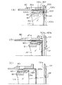
従来、フレア絞りを有するレンズ鏡筒として特開平5−188274号公報のものが提案されている。上記レンズ鏡筒のフレア絞り装置の構成は、図8(A),(B),(C)のフレア絞り動作状態の断面図に示すように、ズーミング,沈胴動作により固定枠101に対して進退する第3レンズ筒60と、ズーミング,沈胴動作時に固定枠101,第3レンズ筒60に対する光軸方向の距離が変化するフロートキー80と、上記フロートキー80に係止され、上記固定枠101と第3レンズ筒60との間に介在するフレア絞り100等で構成されている。
【0003】
上記フレア絞り100は、中央部にフレア絞り開口100cが穿設された薄い円板部材であり、その外周部に前方に向けて形成された環状周壁部100bと、上記環状周壁部100bの前面の3等分位置から前方に向けて延び出した弾性を有する取付片100aと、この取付片100aの先端部の外周面に形成された係止爪100dとが設けられている。
【0004】
上記フレア絞り100は、上記フロートキー80の後方から、その内周壁面80fに沿って前記第3レンズ筒60と干渉しないように嵌合させ、取付片100aの係止爪100dをフロートキー80の長方形状の嵌合孔80eに弾撥的に嵌入させ、フロートキー80の後部に嵌合孔80eの長さ分だけ光軸方向に移動できるように取り付けられる。
【0005】
上記フレア絞り100の沈胴・ズーミング時の動作を上記図8(A),(B),(C)によって説明すると、まず、各レンズ群が沈胴状態のときのフレア絞り100は、図8(A)の状態にある。この沈胴状態ではフレア絞り100は本体101のマスク前側面101aに当接する状態となっている。フレア絞り100の係止爪100dは、フロートキー80の嵌合孔80eの前端寄りに位置している。
【0006】
次に、ワイド状態まで駆動したとき、フレア絞り100は、図8(B)の状態となる。この状態では、フロートキー80は光軸方向に移動するが、第3レンズ筒60は、フロートキー80に対して相対的に光軸方向に距離F2だけ後戻りする。この動きにより第3レンズ筒60と係合しているレンズ支持枠61の後端面61aがフレア絞り100の前端面100fに当接し、フレア絞り100を光軸後方に押し出す。
【0007】
次に、各レンズ群をテレ状態までズーミングした場合には、図8(C)に示す状態となる。この状態では、第3レンズ筒60は、光軸方向に所定量移動している。しかし、この第3レンズ筒60の移動は、フレア絞り100に物理的な影響を及ぼさないのでフロートキー80とフレア絞り100の相対位置関係は、上記ワイド状態から変化しない。そして、フレア絞り開口100cは、第3レンズ群L3 とマスク前側面101aの中間に位置し、テレ状態の有効光束OPを蹴らないようになっている。
【0008】
【発明が解決しようとする課題】
しかしながら、上述の特開平5−188274号公報に開示のレンズ鏡筒のフレア絞り装置においては、フレア絞り100が取付片100aの弾性力でフロートキー80に対し保持されている状態であるので、例えば、図8(B)のワイド状態から図8(C)のテレ状態の間では、フレア絞り100は、係止爪100dが少なくともフロートキー80の嵌合孔80eの範囲内は移動できる状態にある。フレア絞り100自体は、軽い部材であるので移動する可能性は少ないが、本体に強いショックが作用した場合、上記移動できる範囲はずれる可能性があった。
【0009】
本発明は、上述の不具合を解決するためになされたものであって、絞り部材とそれを支持する枠部材との相対距離を精度よく保つことができ、しかも、占有スペ−スを大きくすることなく、組み込まれるレンズ鏡筒の大型化を防止する効果がある絞り装置を提供することを目的とする。
【0010】
【課題を解決するための手段】
本発明の請求項1記載のレンズ鏡筒に設けられたフレア絞り装置は、 上記レンズ鏡筒の光軸方向に延出して該光軸と垂直な方向に弾性変形可能な腕部とフレア絞り開口部とを有したフレア絞り部材と、 上記光軸周りに回動及び上記光軸方向に移動する状態と、上記光軸方向にのみ移動する状態とを有し、周面に設けられた第1の摺動面と、該第1の摺動面とは径方向に段差をもって周面に設けられた第2の摺動面と、これらの摺動面との間に設けられた上記光軸に垂直な段差側面と、これら摺動面同士を連続的に繋げる傾斜面と、を有した枠部材と、 上記枠部材と上記光軸周りに相対的に回動可能で、上記フレア絞り部材を上記光軸周りに回動させぬよう、かつ、上記腕部が光軸方向に移動可能に上記フレア絞り部材の腕部を支持する溝を有し、該溝が上記段差側面と対向するとき、上記段差側面と共に上記第1の摺動面を挟み、上記腕部の端部が上記第1の摺動面を摺動可能として上記フレア絞り開口部と上記枠部材との光軸方向の相対距離を一定に保つことを可能とし、上記溝が上記第2の摺動面に位置するとき上記腕部の端部が上記第2の摺動面上を光軸方向に移動することが可能に設けられた薄板状部材と、を有し、上記枠部材が回動し、かつ、上記光軸方向に移動する状態のときは、上記フレア絞り部材の腕部の端部が上記第1の摺動面上を摺動し、上記枠部材が上記光軸方向および回動方向に移動する状態から上記光軸方向のみに移動する状態に切り換わるときには、上記フレア絞り部材の腕部の端部が上記第1の摺動面から上記傾斜面を摺動して上記第2の摺動面に移動し、上記枠部材が光軸方向にのみ移動する状態のときは、上記フレア絞り部材の腕部の端部が上記第2の摺動面上を光軸方向に摺動可能である。
【0014】
【発明の実施の形態】
以下、本発明の実施の形態を図に基づいて説明する。
図1,2は、本発明の一実施の形態である絞り装置が組み込まれたレンズ鏡筒50の分解斜視図、図3は、可動フレア絞り装着部周りの斜視図、図4は、2,3群枠等の分解斜視図である。図5,6は、上記レンズ鏡筒1の各状態での縦断面図であって、図5は、沈胴状態を示し、図6は、上半部が撮影準備状態およびワイド状態を、下半部がテレ状態を示す。図7は、上記可動フレア絞り装着部縦断面図である。なお、図1,2の分解斜視図における各部材は、その形状を明らかにするために必ずしも組み立て状態時の回転方向姿勢では示されていない。
【0015】
本レンズ鏡筒50は、図1に示す沈胴位置から撮影準備位置間、すなわち、沈胴駆動領域の進退駆動を行う沈胴駆動系50Aと、図2に示す各レンズ群枠の繰り出し駆動を行うレンズ群駆動系50Bと、レンズ群枠部50Cとからなる。
【0016】
上記沈胴駆動系50Aは、図1に示すように、主にカメラ本体に固定支持され、ヘリコイド駆動ギヤ7および駆動リング3を有する固定枠1と、沈胴位置と撮影準備位置間を進退し、上記撮影準備位置でワイド位置からテレ位置間を回動する回転枠2と、後述する移動枠5に回動自在に支持されるヘリコイドリング4と、上記回転枠2と共に沈胴位置と撮影可能位置間を直進移動する移動枠5とからなる。
【0017】
上記沈胴駆動系50Aの各構造部材について詳細に説明すると、上記固定枠1は、カメラ本体51(図5参照)に固着して支持されており、その外周部に貫通する移動枠の突起挿通用直進溝1dが設けられ、内周部にヘイコイド雌ネジ1a、および、直進溝1bが設けられている。さらに、先端部に設けられている駆動リング支持部1cには、駆動リング3が回動駆動可能に装着され、当て板6により、上記駆動リング3のスラスト位置が規制される。また、外周部に軸方向に沿う長尺ギヤ形状のヘリコイドリング駆動ギヤ7が回転可能に支持され、その歯部は、固定枠内周部に露出している。
なお、上記直進溝1b、および、後述する各直進溝は、撮影光学系の光軸Oに平行に設けられる溝とする。
【0018】
上記駆動リング3には、外周部に図示しないズーム駆動系に噛合して駆動されるズームギヤ3aおよび図示しないファインダ駆動系に噛合して駆動されるファインダギヤ3bとが設けられ、内周部に切り欠き状の凹部3cが設けられている。
【0019】
上記回転枠2には、内周部に直進溝2aと、内周前方(被写体側)端部に内周溝2bが設けられ、外周部に突起2cが設けられている。
上記ヘリコイドリング4には、その外周部にヘリコイド雄ネジ4aと駆動ギヤ4bとが設けられている。
【0020】
上記移動枠5には、その外周部に固定枠の溝1dを挿通するストロボ駆動用突起5aと、直進ガイド用突起5b,5c,5dと、上記突起5dで形成される周方向ガイド5eと、先端に突起5fとが設けられ、内周部に3組の複列の直進溝5gが設けられている。さらに、内外周を貫通し、光軸Oに対する斜行溝部を有する3つのカム溝5hが設けられている。
【0021】
上述の各部材で構成される沈胴駆動系50Aにおいて、上記移動枠5にはその周方向ガイド5eに上記ヘリコイドリング4が嵌入し、軸方向位置が規制された状態で回動自在に保持され、さらに、内周部には後述するレンズ群駆動系50Bおよび各レンズ群枠部50Cが回動,進退自在に組み込まれる。その移動枠5は、回転枠2の内周部に嵌入されるが、その嵌入状態で突起5fが内周溝2bと係合するので、回転枠2に対して軸方向位置が規制された状態で回動自在に支持されることになる。
【0022】
上記回転枠2および移動枠5は、それぞれ突起2c,5c,5bを直進溝1b,1dに嵌入させた状態で固定枠1に直進可能状態で挿入される。そのとき、ヘリコイドリング4のヘリコイド雄ネジ4aを固定枠1のヘリコイド雌ネジ1aに、また、駆動ギヤ4bをヘリコイドリング駆動ギヤ7にそれぞれ噛合させる。
【0023】
上記回転枠2および移動枠5の固定枠1への組み付け状態において、移動枠5と回転枠2がフィルム面側の沈胴位置にあるときに(図5参照)、ヘリコイドリング駆動ギヤ7を時計回り(被写体側から見て)B1 方向に回転させると、ヘリコイドリング4が反時計回りC1 方向に回動する。その回動によって移動枠5と回転枠2がD1 方向(被写体側方向)に一体的に撮影準備位置まで繰り出される(図6の上半部分参照)。
【0024】
上記撮影準備位置に到達した状態では、回転枠2は、その突起2cが固定枠1の直進溝1bから外れ、駆動リングの凹部3c側に嵌合する。この状態でズーム駆動系により駆動リング3をE0 方向に回動駆動させると、回転枠2が回動し、撮影準備位置から同方向に僅か回動してワイド位置へ到達し、さらに、同方向に回動するとテレ位置へズーム駆動される。なお、駆動リング3を上述とは逆方向のE1 方向に回転駆動することによって、回転枠2がズーム位置から撮影準備位置へ回動し、さらに、ヘリコイドリング駆動ギヤ7を上述とは逆方向のB0 方向に回転駆動することによって、回転枠2および移動枠5を沈胴位置に繰り込むことができる。
【0025】
次に、上記レンズ群駆動系50Bについて説明する。
レンズ群駆動系50Bは、図2,3,4,7に示すように、主に可動フレア絞り15を支持する枠部材であり、移動枠5内に嵌入して進退駆動され、回転枠2と共に回転するカム枠M11と、カム枠M11と共に回転し、2群枠22を介して進退駆動されるカム枠F12と、キー押さえ14が固着され、レンズ群枠を直進ガイドするキーリング13と、カム枠M11に支持され、直進移動する絞り部材である可動フレア絞り15とからなる。
【0026】
上記レンズ群駆動系50Bを構成する各部材について詳細に説明する。
上記カム枠M11は、上記移動枠5の内周に回動かつ進退可能に嵌入する部材であり、外周部には、可動フレア絞りの先端凸部15cが摺動する第2の摺動面としての外周面11aと、圧入して固着される軸部を持つ3つのカムフォロワ17と、上記カムフォロワ17の軸部に回転自在に嵌入する3つのカムフォロワ18と、段差面としての段差側面11bと、段差周面11cと、所定幅の端部外周面11a′と、段差周面11cの周方向に隣接する周方向傾斜面11dとが設けられている。また、内周部には、フィルム面側端部に設けられる内周溝11eと、3つの直進溝11fと、光軸Oに対し傾斜する斜行溝部を有する3つの2群カム溝11gとが設けられている。
【0027】
なお、上記段差周面11cは、フィルム面側端部に上記外周面11aより一段低く形成される面であって、可動フレア絞り15の腕部の先端凸部15cが摺接する第1の摺動面である。なお、上記段差周面11cの軸方向の幅は、先端凸部15cが周方向に摺動できるように先端凸部15cの軸方向の幅よりも僅かに大きいものとする。
【0028】
また、上記端部外周面11a′は、上記段差周面11cの周方向に設けられる上記外周面11aと同一径の面であって、可動フレア絞り15の先端凸部15cが摺接する所定幅の第2の摺動面である。
【0029】
上記周方向傾斜面11dは、段差周面11cと端部外周面11a′とを連続して繋ぐ周方向の傾斜面である(図3参照)。
段差側面11bは、上記外周面11aと段差周面11cとの間の軸垂直の側面である(図3参照)。
【0030】
上記カム枠F12は、上記カム枠M11の内周に進退可能に嵌合する部材であって、外周部には3つの突起12aが設けられ、内周部には光軸Oに対し傾斜する斜行溝部を有する各3つの1群カム溝12b,2群カム溝12cと、1つの3群カム溝12dとが設けられている。
【0031】
上記可動フレア絞り15は、極薄板の部材であって、中央部に設けられるフレア絞り開口部となる開口15aと、装着前の自由状態で光軸Oに平行な方向から多少内側に向けて延出する弾性変形可能な部分であって、その先端部に周方向に突状の先端凸部15cを有する3つの腕部15bとが設けられている。組み付け状態において、上記先端凸部15cは、上記腕部15bが弾性変形してカム枠M11の外周部11a、または、段差周面11cに所定付勢力で当接するものとする。
【0032】
上記キーリング13は、各レンズ群枠を直進ガイドするための薄板状部材であって、ビス孔13aと、位置決め孔13bと、外周に設けられる3つの複列突起13dと、複列突起13dの間の溝13eと、2つの切り欠き13cと、光軸方向に延出する直進キー13fとが設けられている。
【0033】
なお、上記溝13eの幅は、上記可動フレア絞りの腕部15bが挿通可能であって、先端凸部15cの周方向幅よりも狭い寸法とする。また、上記溝13eの底面の径は、カム枠M11の段差周面11cの径と同等、または、小さいものとする(図3,7参照)。
【0034】
上記キー押さえ14は、円環の一部がカットされた弾性変形可能な部材であり、外周に沿って設けられる鍔14aと、2つのビス用ネジ孔14bと、上記各ネジ孔の側方に設けられ、位置決め孔13bに嵌入可能な位置決めピン14cと、爪状係止部14eを持つ2つの押さえピン14dとが設けられている。
【0035】
上述の各部材で構成されるレンズ群駆動系50Bにおいて、まず、カム枠M11には、その内周の直進溝11fに突起12aを嵌合させた状態でカム枠F12が進退摺動自在に嵌入され、さらに、カム枠M11およびカム枠F12内周部には、後述する各レンズ群枠が進退自在に組み込まれる。
【0036】
レンズ群枠等が組み込まれたカム枠M11は、沈胴駆動系50Aの移動枠5の内周部に回動自在に嵌入され、カム枠Mのカムフォロワ18がカム溝5hに摺動自在に嵌入する。さらに、カムフォロワ18の軸部となるカムフォロワ17は、移動枠5を挿通して、回転枠2の直進溝2aに摺動自在に嵌入する。そして、カムフォロア17は、さらに、回転枠2の直進溝2aに摺動可能となった状態で嵌合している。したがって、回転枠2の回動に伴いカム枠M11が共に回動しなが0ら、移動枠5のカム溝5hによって光軸方向へ進退駆動される。
【0037】
キー押さえ14は、径方向に広げた状態で鍔14aをカム枠M11の内周溝11eに嵌入される。そのキー押さえ14にキーリング13が位置決めピン14cと位置決め孔13bで位置決めされた状態で取り付けられ、ビス16により固着状態とする。したがって、キーリング13は、カム枠M11に対してフィルム側端部に軸方向位置が規制された状態で回動自在に支持される。
【0038】
なお、上述のキーリング取り付け状態では、図7に示すようにキー押さえ14の押さえピン14dがキーリング13の切り欠き13cに嵌入し、押さえピン14dの係止部14eが係合しており、キー押さえ14とキーリング13とは隙間なく保持される。
【0039】
上記キーリング13は、その複列の突起13dが直進進退する移動枠5の複列の直進溝5gに摺動自在に嵌入されるので、回動することなく直進駆動される。さらに、キーリング13の直進キー13fが後述する2群レンズ枠22の直進ガイド孔22cに摺動自在に嵌入されるので、上記2群枠22、および、2群枠に支持される1群枠21,3群枠23が直進ガイドされる。
【0040】
可動フレア絞り15は、その腕部15bが上記キーリングの凹部13eをフィルム面側から挿通し、先端凸部15cが上記カム枠M11の外周面11a、または、段差周面11cに摺接可能な状態で取り付けられる。
【0041】
次に、上記レンズ群枠部50Cについて説明する。
レンズ群枠部50Cは、カム枠M11,カム枠F12に内蔵され、直進移動する各レンズ群保持枠で構成され、上記カム枠F12を介して進退駆動され、1群レンズ41を保持する1群枠21と、上記キーリング13を介して直進ガイドされ、上記カム枠M11によって進退駆動される2群枠22と、カム枠F12を介して進退駆動される可動フォロワ28と、可動フォロワ28を介して進退駆動され、3群レンズ43を保持する3群枠23と、2群枠22に保持されてフォーカシング駆動系(図示せず)により直進駆動され、2群レンズ42を保持するフォーカシング枠29(図5,6参照)とからなる。
【0042】
上記2群枠22には、外周部に各3つのカムフォロワ32,33と、その先端部に3つの突起22bが設けられている。内周部には、キーリングの直進キー13fが嵌入する直進ガイド孔22cと、光軸O方向に沿う軸孔22d,切り欠き22eと、光軸O方向に沿って固着支持されたガイド軸27と、シャッタ44が装着される開口22aが設けられている(図4参照)。
【0043】
上記1群枠21は、開口部21aに1群レンズ41を保持しており、外周部に3つのカムフォロワ31と、内周部に直進溝21bが設けられている。
上記可動フォロワ28は、3群枠23の進退位置を規制する部材であり、2群枠22のガイド軸27の摺動自在に嵌入する軸孔28aと、カムフォロワ28bと、3群枠23を係止するための係止爪28cとが設けられている。
【0044】
上記3群枠23は、2群枠22により直進方向に摺動自在に支持される部材であって、固着支持されるガイド軸24,25と、可動フォロワの係止爪28cとの被係止部23bが設けられ、開口部に3群レンズ43が保持されている。
【0045】
フォーカシング枠29は、2群レンズ42を保持し、上記2群枠22に進退可能に支持され、図示しないフォーカシング駆動系によって進退駆動される(図5,6参照)。
【0046】
以上のような部材からなるレンズ群枠部50Cにおいては、2群枠22には、被写体側外周の突起22bを1群枠の直進溝21bに摺動自在に嵌入させて1群枠21が装着される。また、軸孔22d,切り欠き22eに3群枠のガイド軸24,25を摺動自在に嵌入させて3群枠23が装着される。なお、ガイド軸24には圧縮バネ26が挿入されており、常時、3群枠23は、フィルム面方向への付勢力を受けている。
【0047】
さらに、2群枠22には、そのガイド軸27に軸孔28aを摺動自在に嵌入させて可動フォロワ28が装着される。上記3群枠23がカメラ本体51の当接力を受けない状態では、可動フォロワ28の係止爪28cが3群枠23の被係止部23bに係合することによって3群枠23の位置決めがなされる。
【0048】
上述のレンズ群枠部50Cは、前述したレンズ群駆動系50Bのカム枠M11およびカム枠F12に直進進退可能状態で組み込まれる。また、直進ガイドされるキーリング13の直進キー13fが2群枠22の直進ガイド孔22cに摺動自在に嵌入しているので、2群枠22と共に、1,3群枠21,23および可動フォロワ28も直進進退可能に支持される。
【0049】
そして、1群枠のカムフォロワ31は、カム枠Fの1群カム溝12bに嵌入し、2群枠のカムフォロワ32および33は、カム枠Mの2群カム溝11gとカム枠Fの2群カム溝12cにそれぞれ嵌入する。さらに、可動フォロワのカムフォロワ28bは、カム枠Fの3群カム溝12dに嵌入する。
【0050】
したがって、カム枠M11に対する各枠部材等の進退位置としては、2群枠22は、カム枠M11の2群カム溝11gで位置決めされ、カム枠F12は、2群枠22とカム枠F12の2群カム溝12cによって位置決めされる。さらに、可動フォロワ28がカム枠Fの3群カム溝12dによって位置決めされ、3群枠23は、上記可動フォロワ28の係止部28cを介して位置決めされる。
【0051】
次に、以上のように構成されたレンズ鏡筒50の沈胴,繰り出し動作について説明する。
レンズ鏡筒50が沈胴状態にあるときは、図5に示すように回転枠2等すべての部材は、固定枠1内部に沈胴した状態に保持されている。このとき、3群枠23と可動フレア絞り15は、カメラ本体51のアパーチャ51a近傍に設けられた突起51bで押圧され、収納位置にある。なお、この状態では可動フレア絞り15の先端凸部15cは、図7に示すようにカム枠M11の外周面11a上を摺接しており、前方に移動している。
【0052】
レンズ鏡筒50を沈胴状態から撮影準備状態に駆動するには、ヘリコイドリング駆動ギヤ7をB1 方向に回転させ、ヘリコイドリング4をC1 方向に回動させる。その回動により回転枠2と移動枠5が直進溝1bにガイドされながら一体的にD1 方向に移動し、沈胴位置から撮影準備位置まで繰り出される(図6上半部分参照)。この状態では、移動枠5は、直進溝1d,1bに係合した状態のままであるが、回転枠2は、その突起2cが直進溝1bから解放され、駆動リング3の凹部3cに係合し、駆動リング3によって回動可能な状態となる。
【0053】
上記撮影準備状態からさらにズーム駆動系によって駆動リング3をE0 方向に僅かな角度だけ回動させると、レンズ鏡筒50は図6の上半部分に示すワイド状態となる。
【0054】
また、沈胴状態から撮影準備状態およびワイド状態への駆動過程で1群枠21,2群枠22は、回転枠2,移動枠5と共に繰り出される。3群枠23は、圧縮バネ26の付勢力でカム枠M11および2群枠22から相対的に後方へ離間し、可動フォロワ28の係止爪28cが3群枠23の被係止部23bと係合する位置であるワイド対応位置に相対的に後退する。
【0055】
また、上記駆動過程で可動フレア絞り15は、カム枠M11に対して後退する3群枠23に押圧され、同様に相対的に後退する。そのとき、腕部15bの先端凸部15cは、図3に示すカム枠M11の端部外周面11a′上に到達し、さらに、カム枠M11が僅かワイド位置までE0 方向に回動すると、連続傾斜面11dを摺動降下して段差周面11c上に達する。この状態での可動フレア絞り15は、カム枠M11に対して所定の相対位置にあり、正常なフレア絞りとして機能する。
【0056】
レンズ鏡筒50のワイド状態からテレ状態への駆動は、駆動リング3をE0 方向に回動駆動し、回転枠2を同方向に回動させることによって行われる(図6の下半部参照)。すなわち、回転枠2のE0 方向への回動に伴って、カム枠M11が回動し、移動枠5のカム溝5hに沿って繰り出される。また、カム枠F12も直進溝11fによりカム枠M11と共に回動し、その繰り出し位置は、カム溝12cの嵌入する2群枠22のカムフォロワ33を介して位置決めされる。
【0057】
そして、2群枠22は、キーリング13により直進ガイドされた状態でカムフォロワ32が嵌入するカム枠M11の2群カム溝11gによりテレ対応位置に繰り出される。また、1群枠21は、カムフォロワ31が嵌入するカム枠F12の1群カム溝12bにより同様にテレ対応位置に繰り出される。さらに、3群枠23は、可動フォロワ28がカム枠F12の3群カム溝12dにより位置決めされ、その可動フォロワ28の係止爪28bにより同様にテレ対応位置に位置決めされる。
【0058】
また、ワイド状態からテレ状態をカム枠M11が回動,進退駆動する間、可動フレア絞り15は、キーリング13の溝13eによって回動することなく保持され、その先端凸部15cが段差側面11bとキーリング13の溝13eの側面とで挟まれた状態で段差周面11c上を摺接する。したがって、可動フレア絞り15は、カム枠M11に対して所定の離間位置に確実に保持され、正常なフレア絞りとして機能する。
【0059】
次に、レンズ鏡筒50をワイド状態から撮影準備状態さらに沈胴状態に駆動する場合は、駆動リング3を、一旦、E1 方向に回動させて撮影準備状態とする。その状態で1群枠21,2群枠22は、移動枠5内に繰り込まれている。3群枠23は、カム枠M11に対して相対的にまだ後退した位置にある(図6の上半部分参照)。また、可動フレア絞り15の腕部の先端凸部15cは、カム枠M11がE1 方向に回動するので、段差周面11c上から連続傾斜面11dを摺動して端部外周面11a′上に位置する(図3参照)。
【0060】
その後、ヘリコイドリング駆動ギヤ7をB0 方向に回転駆動して、ヘリコイドリング4をC0 方向に回動させると、移動枠5と共に回転枠2がD0 方向に後退し、回転枠2の突起2cの駆動リング3に対する係合が解放される。さらに、ヘリコイドリング4の回転を続行すると、回転枠2が移動枠5とともにD0 方向に移動し、固定枠1内に収納される沈胴位置まで繰り込まれる(図5参照)。
【0061】
上記の沈胴動作で3群枠23と可動フレア絞り15は、カメラ本体51の突起51bに押圧されて圧縮バネ26の付勢力に抗して相対的に前進する。そして、3群枠23は、2群枠22の内部に収納される(図5参照)。一方、可動フレア絞り15もカム枠M11に対して相対的に光軸方向に前進し、腕部の先端凸部15cがカム枠M11の端部外周面11a′から外周面11a上を前方に摺動し、収納状態となる(図5参照)。
【0062】
以上、説明した上記レンズ鏡筒50に組み込まれる絞り装置によれば、カム枠M11に対する可動フレア絞り15の光軸方向相対位置がズーム動作中は変化することなく、常時、良好なフレア絞り状態を得ることができる。また、沈胴状態でも上記可動フレア絞り15は、確実にカム枠M11内に収納され、占有スペ−スも少なくなり、レンズ鏡筒の小型化にも効果がある。
【0063】
【発明の効果】
上述のように本発明の請求項1に記載の絞り装置によると、絞り部材とそれを支持する枠部材との相対距離を精度よく保つことができ、しかも、占有スペ−スを大きくすることなく、組み込まれるレンズ鏡筒の大型化を防止することも実現できる。
【図面の簡単な説明】
【図1】本発明の一実施の形態である絞り装置が組み込まれたレンズ鏡筒を構成する沈胴駆動系の分解斜視図。
【図2】上記一実施の形態である絞り装置が組み込まれたレンズ鏡筒を構成するレンズ群駆動系およびレンズ群枠部の分解斜視図。
【図3】図1,2のレンズ鏡筒の可動フレア絞り装着部周りの斜視図。
【図4】図1,2のレンズ鏡筒の2,3群枠等の分解斜視図。
【図5】図1,2のレンズ鏡筒の縦断面図であり、沈胴状態を示す。
【図6】図1,2のレンズ鏡筒の縦断面図であり、上半部が撮影準備状態およびワイド状態を、下半部がテレ状態を示す。
【図7】図1,2のレンズ鏡筒の可動フレア絞り装着部周りの縦断面図。
【図8】従来のレンズ鏡筒に組み込まれたフレア絞り装置周りの縦断面図であって、図8(A)が沈胴状態、図8(B)がワイド状態、図8(C)がテレ状態を示す。
【符号の説明】
11 ……カム枠M(枠部材)
11a ……外周面(第2の摺動面)
11a′……端部外周面(第2の摺動面)
11b ……段差側面(段差面)
11d ……連続傾斜面(傾斜面)
11c ……段差周面(第1の摺動面)
15 ……可動フレア絞り(絞り部材)
15b ……腕部(絞り部材の腕部)
15c ……先端凸部(絞り部材の腕部の端部)
50 ……レンズ鏡筒
O ……光軸[0001]
BACKGROUND OF THE INVENTION
The present invention relates to a diaphragm device used in an optical apparatus.
[0002]
[Prior art]
Conventionally, a lens barrel having a flare stop has been proposed in Japanese Patent Laid-Open No. 5-188274. As shown in the sectional views of the flare stop operation state in FIGS. 8A, 8B, and 8C, the lens barrel flare stop device moves forward and backward with respect to the fixed
[0003]
The
[0004]
The
[0005]
The operation of the
[0006]
Next, when driven to the wide state, the
[0007]
Next, when each lens group is zoomed to the tele state, the state shown in FIG. 8C is obtained. In this state, the
[0008]
[Problems to be solved by the invention]
However, in the lens barrel flare stop device disclosed in the above-mentioned JP-A-5-188274, the
[0009]
The present invention has been made to solve the above-described problems, and can maintain the relative distance between the diaphragm member and the frame member that supports the diaphragm member with high accuracy, and also can occupy the space. Without increasing Built-in lens barrel Preventing the increase in size An object is to provide an effective diaphragm device.
[0010]
[Means for Solving the Problems]
Provided in the lens barrel according to claim 1 of the present invention Flare The diaphragm device extends in the optical axis direction of the lens barrel. In a direction perpendicular to the optical axis With elastically deformable arms Flare aperture And had Flare A diaphragm member, a state of rotating around the optical axis and moving in the optical axis direction, and a state of moving only in the optical axis direction, and a first sliding surface provided on the peripheral surface; The first sliding surface is perpendicular to the optical axis provided between the second sliding surface provided on the circumferential surface with a step in the radial direction and these sliding surfaces. Step side A frame member having a surface and an inclined surface that continuously connects these sliding surfaces; and the frame member and the optical axis can be relatively rotated around the frame member, Flare The arm member is movable in the optical axis direction so as not to rotate the aperture member around the optical axis. Flare A groove for supporting the arm of the throttle member, the groove being Step side When facing the surface , the above Step side The first sliding surface is sandwiched with a surface, and the end of the arm portion is slidable on the first sliding surface. Flare aperture It is possible to keep the relative distance between the frame member and the optical axis direction constant, and when the groove is positioned on the second sliding surface, the end of the arm portion is on the second sliding surface. A thin plate-like member provided to be able to move in the optical axis direction, and when the frame member is rotated and moved in the optical axis direction, Flare The end of the arm of the aperture member is on the first sliding surface. Sliding When the frame member is switched from the state moving in the optical axis direction and the rotation direction to the state moving only in the optical axis direction, Flare The end of the arm portion of the aperture member moves the inclined surface from the first sliding surface. Sliding When the frame member moves to the second sliding surface and the frame member moves only in the optical axis direction, Flare An end portion of the arm portion of the diaphragm member can slide in the optical axis direction on the second sliding surface.
[0014]
DETAILED DESCRIPTION OF THE INVENTION
Hereinafter, embodiments of the present invention will be described with reference to the drawings.
1 and 2 are exploded perspective views of a
[0015]
The
[0016]
As shown in FIG. 1, the
[0017]
The structural members of the
The
[0018]
The
[0019]
The
The
[0020]
The moving
[0021]
In the
[0022]
The
[0023]
When the
[0024]
In the state where the photographing preparation position has been reached, the
[0025]
Next, the lens group drive system 50B will be described.
As shown in FIGS. 2, 3, 4, and 7, the lens
[0026]
Each member constituting the lens group driving system 50B will be described in detail.
The cam frame M11 is a member that is fitted to the inner periphery of the moving
[0027]
The stepped
[0028]
Further, the end outer
[0029]
The circumferentially inclined
The
[0030]
The cam frame F12 is a member that is fitted to the inner periphery of the cam frame M11 so as to be able to advance and retract. The cam frame F12 is provided with three protrusions 12a on the outer peripheral portion, and is inclined with respect to the optical axis O on the inner peripheral portion. Each of the three first
[0031]
The
[0032]
The
[0033]
The width of the
[0034]
The
[0035]
In the lens group drive system 50B composed of the above-described members, first, the cam frame F12 is fitted into the cam frame M11 in a state where the projection 12a is fitted in the rectilinear groove 11f on the inner periphery thereof. Further, each lens group frame, which will be described later, is incorporated in the cam frame M11 and the inner peripheral part of the cam frame F12 so as to freely advance and retract.
[0036]
The cam frame M11 incorporating the lens group frame and the like is rotatably fitted into the inner peripheral portion of the moving
[0037]
The
[0038]
In the above-described key ring attached state, as shown in FIG. 7, the
[0039]
The
[0040]
The
[0041]
Next, the lens
The lens
[0042]
The
[0043]
The
The
[0044]
The
[0045]
The focusing
[0046]
In the lens
[0047]
Further, a
[0048]
The lens
[0049]
The
[0050]
Therefore, the
[0051]
Next, the retracting and feeding operation of the
When the
[0052]
To drive the
[0053]
When the
[0054]
Further, the
[0055]
Further, in the above driving process, the
[0056]
The
[0057]
The
[0058]
Further, while the cam frame M11 is rotated and advanced / retracted from the wide state to the tele state, the
[0059]
Next, when the
[0060]
Thereafter, when the helicoid
[0061]
The
[0062]
As described above, according to the diaphragm device incorporated in the
[0063]
【The invention's effect】
As described above, claim 1 of the present invention. In According to the described diaphragm device, the relative distance between the diaphragm member and the frame member that supports the diaphragm member can be maintained with high accuracy, and the occupied space can be maintained. Without increasing Of the lens barrel to be incorporated Preventing enlargement Can also be realized.
[Brief description of the drawings]
FIG. 1 is an exploded perspective view of a retractable drive system constituting a lens barrel in which a diaphragm device according to an embodiment of the present invention is incorporated.
FIG. 2 is an exploded perspective view of a lens group driving system and a lens group frame portion that constitute a lens barrel in which the diaphragm device according to the embodiment is incorporated.
FIG. 3 is a perspective view around a movable flare stop mounting portion of the lens barrel of FIGS.
4 is an exploded perspective view of the lens barrel of FIGS.
5 is a longitudinal sectional view of the lens barrel of FIGS. 1 and 2, showing a retracted state. FIG.
6 is a longitudinal cross-sectional view of the lens barrel of FIGS. 1 and 2, in which the upper half shows a shooting preparation state and a wide state, and the lower half shows a tele state.
7 is a longitudinal sectional view around the movable flare stop mounting portion of the lens barrel of FIGS.
FIG. 8 is a longitudinal sectional view around a flare stop device incorporated in a conventional lens barrel, in which FIG. 8 (A) is in a retracted state, FIG. 8 (B) is in a wide state, and FIG. Indicates the state.
[Explanation of symbols]
11 …… Cam frame M (frame member)
11a ...... Outer peripheral surface (second sliding surface)
11a ′ …… End outer peripheral surface (second sliding surface)
11b ...... Step side surface (step surface)
11d: Continuously inclined surface (inclined surface)
11c ...... Step peripheral surface (first sliding surface)
15 …… Moveable flare diaphragm (diaphragm member)
15b ...... Arm (arm part of diaphragm member)
15c ...... Projection at the tip (end of arm of diaphragm member)
50 ...... Lens barrel
O: Optical axis
Claims (1)
上記レンズ鏡筒の光軸方向に延出して該光軸と垂直な方向に弾性変形可能な腕部とフレア絞り開口部とを有したフレア絞り部材と、
上記光軸周りに回動及び上記光軸方向に移動する状態と、上記光軸方向にのみ移動する状態とを有し、周面に設けられた第1の摺動面と、該第1の摺動面とは径方向に段差をもって周面に設けられた第2の摺動面と、これらの摺動面との間に設けられた上記光軸に垂直な段差側面と、これら摺動面同士を連続的に繋げる傾斜面と、を有した枠部材と、
上記枠部材と上記光軸周りに相対的に回動可能で、上記フレア絞り部材を上記光軸周りに回動させぬよう、かつ、上記腕部が光軸方向に移動可能に上記フレア絞り部材の腕部を支持する溝を有し、該溝が上記段差側面と対向するとき、上記段差側面と共に上記第1の摺動面を挟み、上記腕部の端部が上記第1の摺動面を摺動可能として上記フレア絞り開口部と上記枠部材との光軸方向の相対距離を一定に保つことを可能とし、上記溝が上記第2の摺動面に位置するとき上記腕部の端部が上記第2の摺動面上を光軸方向に移動することが可能に設けられた薄板状部材と、
を有し、上記枠部材が回動し、かつ、上記光軸方向に移動する状態のときは、上記フレア絞り部材の腕部の端部が上記第1の摺動面上を摺動し、上記枠部材が上記光軸方向および回動方向に移動する状態から上記光軸方向のみに移動する状態に切り換わるときには、上記フレア絞り部材の腕部の端部が上記第1の摺動面から上記傾斜面を摺動して上記第2の摺動面に移動し、上記枠部材が光軸方向にのみ移動する状態のときは、上記フレア絞り部材の腕部の端部が上記第2の摺動面上を光軸方向に摺動可能であることを特徴とするレンズ鏡筒に設けられたフレア絞り装置。In flare stop device provided in the lens barrel,
A flare stop member having an arm portion and a flare stop opening portion extending in the optical axis direction of the lens barrel and elastically deformable in a direction perpendicular to the optical axis ;
A first sliding surface provided on a peripheral surface, having a state of rotating around the optical axis and moving in the optical axis direction; and a state of moving only in the optical axis direction; a second sliding surface provided on the peripheral surface with a step in the radial direction to the sliding surface, perpendicular stepped side surface to the optical axis provided between these sliding surfaces, these slides A frame member having an inclined surface that continuously connects the surfaces;
Can relatively rotate around the frame member and the optical axis, the flare diaphragm member as not to rotate around the optical axis, and the diaphragm member movably above flare the arm portion in the direction of the optical axis the arm portion has a groove for supporting the when the groove is facing the stepped side surface, sandwiching the first sliding surface together with the stepped side surface, the arm portion of the end the first sliding The moving surface can be slidable, the relative distance in the optical axis direction between the flare aperture opening and the frame member can be kept constant, and the arm portion when the groove is positioned on the second sliding surface A thin plate-like member provided such that an end of the second sliding surface can move in the optical axis direction on the second sliding surface;
The a, the frame member is rotated, and, when the state moved in the optical axis direction, the end portion of the arm portion of the flare diaphragm member slides the first sliding surface above, When the frame member switches from the state in which the frame member moves in the optical axis direction and the rotation direction to the state in which the frame member moves only in the optical axis direction, the end of the arm portion of the flare stop member is separated from the first sliding surface. When the inclined surface slides to move to the second sliding surface and the frame member moves only in the optical axis direction, the end of the arm portion of the flare stop member is the second A flare stop device provided in a lens barrel, which is slidable in the optical axis direction on a sliding surface.
Priority Applications (2)
| Application Number | Priority Date | Filing Date | Title |
|---|---|---|---|
| JP23750898A JP4144943B2 (en) | 1998-08-24 | 1998-08-24 | Aperture device |
| US09/377,798 US6443636B1 (en) | 1998-08-24 | 1999-08-20 | Stop device |
Applications Claiming Priority (1)
| Application Number | Priority Date | Filing Date | Title |
|---|---|---|---|
| JP23750898A JP4144943B2 (en) | 1998-08-24 | 1998-08-24 | Aperture device |
Publications (2)
| Publication Number | Publication Date |
|---|---|
| JP2000066078A JP2000066078A (en) | 2000-03-03 |
| JP4144943B2 true JP4144943B2 (en) | 2008-09-03 |
Family
ID=17016369
Family Applications (1)
| Application Number | Title | Priority Date | Filing Date |
|---|---|---|---|
| JP23750898A Expired - Fee Related JP4144943B2 (en) | 1998-08-24 | 1998-08-24 | Aperture device |
Country Status (2)
| Country | Link |
|---|---|
| US (1) | US6443636B1 (en) |
| JP (1) | JP4144943B2 (en) |
Families Citing this family (6)
| Publication number | Priority date | Publication date | Assignee | Title |
|---|---|---|---|---|
| JP4487531B2 (en) * | 2003-10-02 | 2010-06-23 | ソニー株式会社 | Lens barrel |
| JP5143644B2 (en) * | 2008-07-01 | 2013-02-13 | Hoya株式会社 | Support structure for light shielding member of lens barrel |
| WO2012102004A1 (en) | 2011-01-24 | 2012-08-02 | パナソニック株式会社 | Lens barrel |
| JPWO2012102007A1 (en) | 2011-01-24 | 2014-06-30 | パナソニック株式会社 | Lens barrel |
| WO2012102006A1 (en) | 2011-01-24 | 2012-08-02 | パナソニック株式会社 | Lens barrel |
| WO2012102001A1 (en) | 2011-01-24 | 2012-08-02 | パナソニック株式会社 | Lens barrel |
Family Cites Families (7)
| Publication number | Priority date | Publication date | Assignee | Title |
|---|---|---|---|---|
| JP3041083B2 (en) * | 1991-05-31 | 2000-05-15 | オリンパス光学工業株式会社 | Lens barrel |
| JPH05307137A (en) * | 1992-01-07 | 1993-11-19 | Olympus Optical Co Ltd | Lens barrel |
| JP3190403B2 (en) * | 1992-01-08 | 2001-07-23 | オリンパス光学工業株式会社 | Lens barrel |
| JPH0584908U (en) * | 1992-04-17 | 1993-11-16 | 旭光学工業株式会社 | Play removal device for zoom lens barrel |
| JP3276171B2 (en) * | 1992-08-17 | 2002-04-22 | 旭光学工業株式会社 | Zoom lens barrel |
| JP3435580B2 (en) * | 1993-04-30 | 2003-08-11 | コニカ株式会社 | Zoom lens barrel and camera |
| JP3676509B2 (en) * | 1996-08-27 | 2005-07-27 | ペンタックス株式会社 | Zoom lens barrel and its back focus adjustment method |
-
1998
- 1998-08-24 JP JP23750898A patent/JP4144943B2/en not_active Expired - Fee Related
-
1999
- 1999-08-20 US US09/377,798 patent/US6443636B1/en not_active Expired - Lifetime
Also Published As
| Publication number | Publication date |
|---|---|
| US6443636B1 (en) | 2002-09-03 |
| JP2000066078A (en) | 2000-03-03 |
Similar Documents
| Publication | Publication Date | Title |
|---|---|---|
| JP4285846B2 (en) | Lens barrel | |
| US6741401B2 (en) | Lens barrel | |
| US6717744B2 (en) | Lens barrel | |
| US7753598B2 (en) | Lens barrel | |
| JP2000250092A (en) | Diaphragm device | |
| US7773871B2 (en) | Retractable photographic lens | |
| US20060045516A1 (en) | Retractable lens system | |
| US6778334B2 (en) | Lens barrel | |
| US7088524B2 (en) | Lens barrel having a lens barrier mechanism | |
| JP4144943B2 (en) | Aperture device | |
| US6751032B2 (en) | Lens barrel | |
| US7864458B2 (en) | Lens barrel | |
| US6256458B1 (en) | Lens housing | |
| US6906871B2 (en) | Cam mechanism for lens barrel | |
| JP4166338B2 (en) | Lens barrel | |
| JP2811185B2 (en) | Zoom lens device | |
| JP2000131588A (en) | Lens barrel | |
| JP2000131589A (en) | Cam follower and lens barrel | |
| JP2000131588A5 (en) | ||
| US6268968B1 (en) | Lens housing | |
| JP3836232B2 (en) | Lens drive mechanism | |
| US20040114253A1 (en) | Lens distance-varying mechanism, and step-zoom lens incorporating the same | |
| US6954587B2 (en) | Switching/moving structure of a zoom lens | |
| JP2000089078A (en) | Lens barrel | |
| JP2000081558A (en) | Lens barrel |
Legal Events
| Date | Code | Title | Description |
|---|---|---|---|
| A621 | Written request for application examination |
Free format text: JAPANESE INTERMEDIATE CODE: A621 Effective date: 20050413 |
|
| A977 | Report on retrieval |
Free format text: JAPANESE INTERMEDIATE CODE: A971007 Effective date: 20061102 |
|
| A131 | Notification of reasons for refusal |
Free format text: JAPANESE INTERMEDIATE CODE: A131 Effective date: 20061114 |
|
| A521 | Request for written amendment filed |
Free format text: JAPANESE INTERMEDIATE CODE: A523 Effective date: 20061226 |
|
| A131 | Notification of reasons for refusal |
Free format text: JAPANESE INTERMEDIATE CODE: A131 Effective date: 20070213 |
|
| A521 | Request for written amendment filed |
Free format text: JAPANESE INTERMEDIATE CODE: A523 Effective date: 20070322 |
|
| A02 | Decision of refusal |
Free format text: JAPANESE INTERMEDIATE CODE: A02 Effective date: 20070424 |
|
| A521 | Request for written amendment filed |
Free format text: JAPANESE INTERMEDIATE CODE: A523 Effective date: 20080519 |
|
| A01 | Written decision to grant a patent or to grant a registration (utility model) |
Free format text: JAPANESE INTERMEDIATE CODE: A01 |
|
| A61 | First payment of annual fees (during grant procedure) |
Free format text: JAPANESE INTERMEDIATE CODE: A61 Effective date: 20080617 |
|
| FPAY | Renewal fee payment (event date is renewal date of database) |
Free format text: PAYMENT UNTIL: 20110627 Year of fee payment: 3 |
|
| FPAY | Renewal fee payment (event date is renewal date of database) |
Free format text: PAYMENT UNTIL: 20120627 Year of fee payment: 4 |
|
| FPAY | Renewal fee payment (event date is renewal date of database) |
Free format text: PAYMENT UNTIL: 20120627 Year of fee payment: 4 |
|
| FPAY | Renewal fee payment (event date is renewal date of database) |
Free format text: PAYMENT UNTIL: 20130627 Year of fee payment: 5 |
|
| LAPS | Cancellation because of no payment of annual fees |