EP1679437A1 - Dispositif d'amortissement de vibrations, ainsi que moteur à combustion interne comprenant un tel dispositif - Google Patents
Dispositif d'amortissement de vibrations, ainsi que moteur à combustion interne comprenant un tel dispositif Download PDFInfo
- Publication number
- EP1679437A1 EP1679437A1 EP06300009A EP06300009A EP1679437A1 EP 1679437 A1 EP1679437 A1 EP 1679437A1 EP 06300009 A EP06300009 A EP 06300009A EP 06300009 A EP06300009 A EP 06300009A EP 1679437 A1 EP1679437 A1 EP 1679437A1
- Authority
- EP
- European Patent Office
- Prior art keywords
- vibrations
- damping device
- injector
- decoupling means
- damping
- Prior art date
- Legal status (The legal status is an assumption and is not a legal conclusion. Google has not performed a legal analysis and makes no representation as to the accuracy of the status listed.)
- Granted
Links
Images

Classifications
-
- F—MECHANICAL ENGINEERING; LIGHTING; HEATING; WEAPONS; BLASTING
- F02—COMBUSTION ENGINES; HOT-GAS OR COMBUSTION-PRODUCT ENGINE PLANTS
- F02M—SUPPLYING COMBUSTION ENGINES IN GENERAL WITH COMBUSTIBLE MIXTURES OR CONSTITUENTS THEREOF
- F02M61/00—Fuel-injectors not provided for in groups F02M39/00 - F02M57/00 or F02M67/00
- F02M61/14—Arrangements of injectors with respect to engines; Mounting of injectors
-
- F—MECHANICAL ENGINEERING; LIGHTING; HEATING; WEAPONS; BLASTING
- F16—ENGINEERING ELEMENTS AND UNITS; GENERAL MEASURES FOR PRODUCING AND MAINTAINING EFFECTIVE FUNCTIONING OF MACHINES OR INSTALLATIONS; THERMAL INSULATION IN GENERAL
- F16F—SPRINGS; SHOCK-ABSORBERS; MEANS FOR DAMPING VIBRATION
- F16F15/00—Suppression of vibrations in systems; Means or arrangements for avoiding or reducing out-of-balance forces, e.g. due to motion
- F16F15/02—Suppression of vibrations of non-rotating, e.g. reciprocating systems; Suppression of vibrations of rotating systems by use of members not moving with the rotating systems
-
- F—MECHANICAL ENGINEERING; LIGHTING; HEATING; WEAPONS; BLASTING
- F16—ENGINEERING ELEMENTS AND UNITS; GENERAL MEASURES FOR PRODUCING AND MAINTAINING EFFECTIVE FUNCTIONING OF MACHINES OR INSTALLATIONS; THERMAL INSULATION IN GENERAL
- F16F—SPRINGS; SHOCK-ABSORBERS; MEANS FOR DAMPING VIBRATION
- F16F7/00—Vibration-dampers; Shock-absorbers
-
- F—MECHANICAL ENGINEERING; LIGHTING; HEATING; WEAPONS; BLASTING
- F02—COMBUSTION ENGINES; HOT-GAS OR COMBUSTION-PRODUCT ENGINE PLANTS
- F02M—SUPPLYING COMBUSTION ENGINES IN GENERAL WITH COMBUSTIBLE MIXTURES OR CONSTITUENTS THEREOF
- F02M2200/00—Details of fuel-injection apparatus, not otherwise provided for
- F02M2200/09—Fuel-injection apparatus having means for reducing noise
-
- F—MECHANICAL ENGINEERING; LIGHTING; HEATING; WEAPONS; BLASTING
- F02—COMBUSTION ENGINES; HOT-GAS OR COMBUSTION-PRODUCT ENGINE PLANTS
- F02M—SUPPLYING COMBUSTION ENGINES IN GENERAL WITH COMBUSTIBLE MIXTURES OR CONSTITUENTS THEREOF
- F02M2200/00—Details of fuel-injection apparatus, not otherwise provided for
- F02M2200/30—Fuel-injection apparatus having mechanical parts, the movement of which is damped
- F02M2200/306—Fuel-injection apparatus having mechanical parts, the movement of which is damped using mechanical means
Definitions
- the present invention relates to a vibration damping device for mounting a first apparatus, a source of vibration, on a second apparatus, subjected to thermal stresses and capable of receiving and transmitting vibrations, as well as an electric motor. internal combustion comprising such a device and a motor vehicle comprising such a device.
- the present invention finds a particularly effective application in the field of the design of powertrain units of motor vehicles, these powertrain units being, in the given context, devices subjected to thermal stresses and likely to receive vibrations and transmit them.
- the vibrations are generated by a first device as a source of vibration, for example a fuel injector, which is mounted on a second device, the power unit.
- the present invention provides a damping device for damping the vibrations generated by the injectors or by any other apparatus generating vibrations.
- Injectors which are only one source among other sources of noise and vibrations in a motor vehicle, are intended to be mounted, to perform their functions, on a second device, in this case an engine block provided with at least one combustion chamber in which such an injector must inject a fuel.
- Another source of vibration is, for example, the pump of a washer.
- Injectors are also a source of vibrations for two reasons. Firstly, the injectors are a source of vibrations because of its internal moving parts which are activated for the consecutive preparation of the fuel portions intended to be injected into the combustion chamber or chambers according to the engine speed. These parts are generally solicited in translatory and oscillatory movement and the consecutive vibrations of the injector produce acoustic radiation directly audible.
- the injectors are then source of vibrations because of the dynamic forces they produce on the cylinder head, to which they are attached, and on the entire engine during the preparation and injection of fuel portions.
- Each change of pressure, and in particular each discharge of pressure generates vibrations. These vibrations propagate solidly in the motor and then produce audible acoustic radiation.
- US-A-5,636,827 describes a means for reducing the impact of vibrations generated inside an injector.
- This solution is to soften the needle of the injector, in particular using notches, to reduce the stiffness of the impacts that the needle generates in operation on the nozzle of the injector.
- This solution is limited to the injector itself and does not take into account the implantation of the injector in the cylinder head of a heat engine.
- the object of the invention is to propose a device that makes it possible to damp vibrations and noise generated by a first apparatus, a source of vibrations, such as an injector, intended to be mounted on a second apparatus, subject to constraints thermal and capable of receiving and transmitting vibrations.
- the object of the present invention is achieved with a vibration damping device for mounting a first apparatus, source of vibration, on a second apparatus, subjected to thermal stresses and capable of receiving and transmitting vibrations, device comprising vibration transmission decoupling means made of a friction material.
- the present invention thus provides a treatment for primarily damping the acoustic radiation structures vibrated by a first device, a source of vibration, for example an injector in operation.
- the device of the invention then intervenes at the interface between the two devices mounted on one another. According to the example chosen, it is the interface between an injector, or injectors, and a cylinder head on which they are mounted.
- the device of the invention provides a local damping treatment at the interface between the injectors and the cylinder head on which they are mounted. Thanks to this arrangement of the invention, the possibility of usefully dissipate, especially close to the source of vibration, vibratory energy. The vibratory energy thus dissipated is no longer available to excite the bolt by transmission of vibrations.
- vibration transmission decoupling means made of a friction material
- a friction material is used a material well suited to the harsh environment, that is an engine block including a cylinder head and the rest of the engine base on which injectors are mounted.
- a friction material is for example an organic matrix composite.
- thermal and thermomechanical stresses that are encountered at the interface between an injector and the cylinder head on which it is mounted are quite important.
- the static prestressing exerted along the axis of the injector, in order to seal the seal between the injector and the cylinder head is of the order of 10 000 N.
- the pressure inside a cylinder can reach 160 bar.
- the environment of the nose of the injector, which is in contact with the combustion gases can reach temperatures of the order of 300 ° C.
- the decoupling means are advantageously shaped either for damping axial vibrations or for damping transverse vibrations.
- decoupling means such as washers intended to be arranged at the interface between the first source apparatus and the second receiver apparatus.
- the present invention thus makes it possible to treat the vibrations generated by the injector by inserting at the interface between the injector and the yoke, a dissipative material with respect to the vibratory energy but resistant to the thermomechanical stresses existing on this particular interface.
- this treatment can be located near the source and on small surfaces, as opposed to large surfaces or bodies. spacers of certain dimensions.
- the effects exerted on specific parts of the assembly of the first vibration source device are thus concentrated on the second, and it is used at the same time for two materials.
- the friction materials allow a precise manufacture of the decoupling means, which contributes positively to their use in places by definition tight, and one acts very close to the source of noise or vibrations.
- the decoupling means comprise a sleeve for receiving at least a portion of the first device, a source of vibration, this sleeve then being inserted between the first device and an obviously practiced in a second device for receiving the first device.
- the decoupling means comprise a flat damping element intended to be arranged at the bottom of a recess of the second apparatus in which the first apparatus is to be housed.
- the object of the invention is moreover achieved by an internal combustion engine, with injection, comprising at least one fuel injector mounted on a cylinder block of the engine, this engine comprising a damping device with the characteristics described above.
- the object of the invention is also achieved with a motor vehicle comprising a damping device as described above.
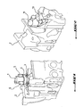
- FIGS. 1 and 2 show, by way of example for an arrangement of a first device, a source of vibrations, on a second apparatus subjected to thermal stresses and capable of receiving and transmitting vibrations, a fuel injector mounted on a yoke and fixed thereto using a flange as shown in Figure 1 or with a fork as shown in Figure 2.
- an injector 1 is mounted on a cylinder head 2 on two small columns 3 integral with the cylinder head 2.
- a flange 4 is used which encloses the injector head and the 'presses the balusters 3.
- the flange 4 is immobilized on the balusters 3 with two nuts 5 exerting the necessary support on the flange 4 so that the latter maintains the injector 1 firmly on the yoke 2.
- an injector 11 is mounted on a yoke 2 by means of a fork 12.
- the fork 12 is screwed onto the yoke 2 by means of a nut 13 engaged on a threaded rod integral with the yoke 2.
- the fork 12 is arranged so as to partially surround, by one of its two opposite ends, the head of the injector 11 and to bear, by the other of its two opposite ends, on the cylinder head 2.
- the threaded rod and the nut 13 are arranged between the two opposite ends of the fork 12 and pass through the fork 12.
- the fork 12 can also be immobilized on the yoke 2 by means of a screw engaging in a suitable thread of the breech. By tightening the nut 13, a lever is exerted on the fork, thanks to which the fork bears on the head of the injector 11 and immobilizes it on the cylinder head 2.
- the injector is fixed on the cylinder head according to one or the other of the two generic examples of attachment shown in FIGS. 1 or 2 or that the injector is fixed in yet another way, it is common ground that the injector is in direct contact with the cylinder head and that all the vibrations generated by the injector can be transmitted or radiated in the form of noise without particular attenuation or damping.
- FIG. 3 shows the fastening principle shown in Figure 1 in the form of a simplified section.
- FIG. 3 shows an injector 1 housed in a recess 6 made in the cylinder head 2.
- the injector 1 is mainly based on the bottom 7 of the recess 6.
- a seal 8 is placed on the bottom of the recess 6.
- the injector 1 is supported by the other on the columns 3 on which it is supported by means of the flange 4.
- the support is exerted with the help of the nuts 5
- the axial spacing between the flange 4 and the pillars 3, as shown in FIG. 3, is not drawn to scale with respect to a thickness of the wall. flange 4, but was exaggerated for design reasons.
- the injector represented in the drawings is only one example among others of a first device, a source of vibrations, used in the field of motor vehicles and which is mounted on a second apparatus, subjected to thermal stresses and capable of receiving and transmitting vibrations, for example the power unit shown in the drawings by the cylinder head 2.
- the first device 1 bears on the second device 2 mainly at three points, namely on the two columns 3 and on the bottom 7 of the recesses 6. This means that all the vibrations generated inside the first device 1 are received by the second device 2 at these three points of contact and that, if necessary, the second device 2 transmits these vibrations elsewhere, for example, through the suspension of the powertrain, on the body of the vehicle, or even in the ambient air.
- the vibrations generated by the first device 1, which are also noted outside by their direct radiation, are transmitted in various ways on the second device 2, and generally amplified.
- the body of the first apparatus 1 When the body of the first apparatus 1 has a shape and dimensions such that it marries, at least in part, the walls of the recess 6 in which the first apparatus is housed, there is a path for transmitting the vibrations emanate from the first apparatus 1 on the second apparatus 2. This path is formed by the parts of the body wall of the first apparatus 1 and the wall of the recess 6 which are in intimate contact with each other. According to the presentation of Figure 3, the body of the injector 1 fully marries the recess 6.
- the mounting of the first device 1 on the second device 2, in this case the fixing of an injector 1 in a cylinder head 2, is modified by the addition of the elements of a device vibration damping according to the invention.
- a first device 1 is inserted into a recess 6 of the second device, the first device 1 taking particular support on the bottom 7 of the recess 6.
- the first Apparatus 1 also bears on the columns 3, and this by means of a flange 4, by means of which the first apparatus 1 is immobilized by the action of strong stresses in the recess 6.
- the flange 4 is supported on the columns 3 to 1. With the aid of nuts 5 engaged on a threaded part of the columns 3.
- FIG. 4 represents the axial spacing between the flange 4 and the columns 3 with an exaggerated spacing for drawing purposes.
- the first type of element consists of washers or seals 21, 22 arranged so as to damp the axial vibrations of the first device 1.
- the seals 21, or washers 21, are made of a friction material such as that which is uses, for example, for brake pads.
- the washers 21 are arranged on the columns 3 so as to be interposed between the bearing head of the columns 3 and the flange 4.
- Another seal is that referenced 22. It is disposed at the bottom of the recess 6, that is to say between the metal gasket 8 and the bottom 7 of the recess 6.
- First vibration source devices such as injectors, not only generating axial vibrations, but also vibrations that can be spread substantially transversely with respect to the longitudinal extent of the first device 1, decoupling means forming elements of the device according to the invention, specially shaped to damp transverse vibrations, are provided.
- decoupling means forming elements of the device according to the invention, specially shaped to damp transverse vibrations, are provided.
Landscapes
- Engineering & Computer Science (AREA)
- General Engineering & Computer Science (AREA)
- Mechanical Engineering (AREA)
- Acoustics & Sound (AREA)
- Combustion & Propulsion (AREA)
- Physics & Mathematics (AREA)
- Chemical & Material Sciences (AREA)
- Aviation & Aerospace Engineering (AREA)
- Vibration Prevention Devices (AREA)
- Fuel-Injection Apparatus (AREA)
- Arrangement Or Mounting Of Propulsion Units For Vehicles (AREA)
- Cylinder Crankcases Of Internal Combustion Engines (AREA)
- Braking Arrangements (AREA)
- Portable Nailing Machines And Staplers (AREA)
Abstract
Description
- La présente invention concerne un dispositif d'amortissement de vibrations pour le montage d'un premier appareil, source de vibrations, sur un second appareil, soumis à des contraintes thermiques et susceptible de recevoir et de transmettre les vibrations, ainsi qu'un moteur à combustion interne comprenant un tel dispositif et un véhicule automobile comprenant un tel dispositif.
- La présente invention trouve une application particulièrement efficace dans le domaine de la conception de groupes moto-propulseurs de véhicules automobiles, ces groupes moto-propulseurs étant, dans le contexte donné, des appareils soumis à des contraintes thermiques et susceptibles de recevoir des vibrations et de les transmettre. Les vibrations sont engendrées par un premier appareil en tant que source de vibrations, par exemple un injecteur de carburant, qui est monté sur un second appareil, le groupe moto-propulseur.
- La présente invention propose un dispositif d'amortissement destiné à amortir les vibrations engendrées par les injecteurs ou par tout autre appareil engendrant des vibrations.
- Lors de la conception d'un véhicule automobile, il est de tradition depuis longtemps de prévoir des moyens destinés à empêcher la génération de vibrations ou, pour le moins, destinés à les amortir. Un exemple typique sont les amortisseurs de vibrations que l'on utilise dans la suspension du bloc moteur dans le châssis du véhicule. Outre les amortisseurs hydrauliques, on utilise à cet effet des blocs de caoutchouc.
- Toutefois, les vibrations de la grande mécanique d'un véhicule automobile ne sont pas les seules sources de bruit vers lesquels les constructeurs de véhicules automobiles se tournent de plus en plus. Les approches récentes pour diminuer le bruit qu'un véhicule automobile en général et qu'un groupe moto-propulseur en particulier génère, sont de plus en plus dirigées vers les sources mêmes des bruits. En effet, les approches les plus efficaces en vue de réduire le bruit et les vibrations, consistent à agir au plus près de la source, voire directement sur la cause du bruit lorsque cela est possible.
- Un des bruits les plus prononcés d'un groupe moto-propulseur dans un véhicule automobile est le bruit généré par les injecteurs, et cela particulièrement dans les moteurs à allumage par compression.
- Les injecteurs, qui ne sont qu'une source parmi d'autres sources de bruit et de vibrations dans un véhicule automobile, sont destinés à être montés, pour exercer leurs fonctions, sur un second appareil, en l'occurrence un bloc moteur pourvu d'au moins une chambre de combustion dans laquelle un tel injecteur doit injecter un carburant. Une autre source de vibration est, par exemple, la pompe d'un lave-glace. Toutefois, en comparant ces deux exemples de sources de vibrations, on remarque la difficulté particulière à laquelle le concepteur d'un appareil doit faire face, lorsqu'il essaie de réduire les vibrations : il s'agit des contraintes thermiques et mécaniques auxquelles des appareils tels les injecteurs de carburant et leur environnement de montage sont exposés.
- Les injecteurs sont d'ailleurs source de vibrations à double titre. D'abord, les injecteurs sont source de vibrations en raison de ses parties mobiles internes qui sont activées pour la préparation consécutive des portions de carburant destinées à être injectées dans la ou les chambres de combustion suivant le régime du moteur. Ces pièces sont en général sollicitées en mouvement translatoire et oscillatoire et les vibrations consécutives de l'injecteur produisent un rayonnement acoustique directement audible.
- Toutefois, les injecteurs sont ensuite source de vibrations en raison des efforts dynamiques qu'ils produisent sur la culasse, à laquelle ils sont fixés, et sur l'ensemble du moteur pendant la préparation et l'injection de portions de carburant. Chaque changement de pression, et notamment chaque décharge de pression, engendre des vibrations. Ces vibrations se propagent par voie solide dans le moteur puis produisent un rayonnement acoustique audible.
- La nature double en tant que source vibro-acoustique a été reconnue déjà dans l'état de la technique et a donné lieu à des solutions agissant plutôt au premier niveau ou plutôt au second niveau.
- Ainsi, le document US-A-5 636 827 décrit un moyen pour réduire l'impact des vibrations engendrées à l'intérieur d'un injecteur. Cette solution consiste à assouplir l'aiguille de l'injecteur, notamment à l'aide d'encoches, afin de diminuer la raideur des impacts que l'aiguille engendre en fonctionnement sur la buse de l'injecteur. Cette solution se limite à l'injecteur lui-même et ne prend pas en compte l'implantation de l'injecteur dans la culasse d'un moteur thermique.
- Un autre exemple d'un moyen d'assouplissement des vibrations est décrit dans le document EP-A-1 460 262. Ce document enseigne un moyen dit d'amortissement harmonique, réalisé en matière plastique ou en métal, qui est disposé à l'intérieur de l'injecteur, par exemple sous la forme d'un insert tubulaire disposé à l'intérieur du tube d'entrée de l'injecteur. Cette solution se limite à l'injecteur lui-même et ne prend pas en compte l'implantation de l'injecteur dans la culasse d'un moteur thermique. En outre, le taux d'amortissement apporté par les matériaux préconisés par cette solution est généralement faible.
- L'environnement de l'injecteur est en revanche pris en compte dans l'enseignement du document US-A-6 382 532. Ce document enseigne des intercalaires destinés à être intégrés entre différentes parties d'un injecteur. Toutefois, les matériaux proposés dans ce document pour obtenir les effets d'un amortissement, sont des viscoélastiques classiques. De tels matériaux sont inutilisables à des températures élevées comme on le rencontre dans la partie inférieure d'un injecteur, c'est-à-dire à proximité de la chambre de combustion et notamment en contact avec la culasse.
- Les effets mécaniques et le principe de fonctionnement des injecteurs ne pouvant être changés, il s'agit alors de diminuer, voire de faire disparaître au moins le rayonnement acoustique des structures mises en vibration par l'injecteur en fonctionnement.
- Le but de l'invention est de proposer un dispositif qui permette d'amortir des vibrations et du bruit générés par un premier appareil, source de vibrations, tel qu'un injecteur, destiné à être monté sur un second appareil, soumis à des contraintes thermiques et susceptible de recevoir et transmettre des vibrations.
- Le but de la présente invention est atteint avec un dispositif d'amortissement de vibrations pour le montage d'un premier appareil, source de vibrations, sur un second appareil, soumis à des contraintes thermiques et susceptible de recevoir et de transmettre les vibrations, ce dispositif comprenant des moyens de découplage de transmission des vibrations réalisés en un matériau de friction.
- La présente invention propose ainsi un traitement permettant d'amortir principalement le rayonnement acoustique de structures mises en vibration par un premier appareil, source de vibrations, par exemple un injecteur en fonctionnement. Le dispositif de l'invention intervient alors à l'interface entre les deux appareils montés l'un sur l'autre. Selon l'exemple choisi, il s'agit de l'interface entre un injecteur, ou des injecteurs, et une culasse sur laquelle ils sont montés.
- Le dispositif de l'invention apporte un traitement amortissant local à l'interface entre les injecteurs et la culasse sur laquelle ils sont montés. Grâce à cette disposition de l'invention, on crée la possibilité de dissiper utilement, notamment très près de la source des vibrations, de l'énergie vibratoire. L'énergie vibratoire ainsi dissipée n'est donc plus disponible pour exciter la culasse par transmission de vibrations.
- De plus, les moyens utilisés sont spécialement étudiés au vu des contraintes thermiques et mécaniques dont il s'agit de tenir compte.
- En effet, en ayant choisi des moyens de découplage de transmission de vibrations réalisés en un matériau de friction, on emploie un matériau bien adapté à l'environnement difficile, que constitue un bloc moteur et notamment une culasse et le reste de la base moteur sur lesquels les injecteurs sont montés. Un tel matériau de friction est par exemple un composite à matrice organique.
- Les contraintes thermiques et thermomécaniques que l'on rencontre à l'interface entre un injecteur et la culasse sur laquelle elle est montée, sont assez importantes. A titre d'exemple, les précontraintes statiques exercées selon l'axe de l'injecteur, afin d'assurer l'étanchéité du joint entre l'injecteur et la culasse, sont de l'ordre de 10 000 N. De même, la pression à l'intérieur d'un cylindre peut atteindre 160 bar. Enfin, l'environnement du nez de l'injecteur, qui est en contact avec les gaz de combustion, peut atteindre des températures de l'ordre de 300°C.
- En choisissant les matériaux de friction, que l'on connaît par exemple des patins de frein et d'autres moyens de friction, on dispose à la fois d'un matériau mécaniquement résistant, capable de subir les contraintes thermiques élevées énoncées ci avant et doté d'un pouvoir amortissant intéressant.
- Les moyens de découplage sont avantageusement conformés soit pour amortir des vibrations axiales, soit pour amortir des vibrations transversales.
- Selon le principe de la présente invention de traiter les nuisances au plus proche de leurs sources, il convient en particulier d'utiliser des moyens de découplage telles des rondelles destinées à être disposées à l'interface entre le premier appareil source et le second appareil récepteur.
- La présente invention permet ainsi de traiter les vibrations engendrées par l'injecteur en insérant à l'interface entre l'injecteur et la culasse, un matériau dissipatif en ce qui concerne l'énergie vibratoire mais résistant aux contraintes thermomécaniques existant sur cette interface particulière. En choisissant comme matériau des composites à matrice organique, fabriqués sous la forme de rondelles ou de manchons ou de toute autre forme adéquate, on peut localiser ce traitement près de la source et sur de petites surfaces, par opposition à des surfaces grandes ou des corps intercalaires de certaines dimensions. On concentre ainsi les effets exercés sur des parties précises du montage du premier appareil source de vibrations sur le second, et on l'utilise en même temps pour deux matériaux. Par ailleurs, les matériaux de friction permettent une fabrication précise des moyens de découplage, ce qui contribue positivement à leur utilisation à des endroits par définition serrée, et on agit très près de la source de bruit ou de vibrations.
- En ce qui concerne la forme et l'emplacement des moyens de découplage selon l'invention, il est concevable que les moyens de découplage comprennent un manchon destiné à recevoir au moins une partie du premier appareil, source de vibrations, ce manchon étant alors intercalé entre le premier appareil et un évidemment pratiqué dans un second appareil destiné à recevoir le premier appareil. Selon une autre variante, les moyens de découplage comprennent un élément d'amortissement plat destiné à être disposé au fond d'un évidement du second appareil dans lequel le premier appareil doit être logé.
- Le but de l'invention est par ailleurs atteint par un moteur à combustion à interne, à injection, comprenant au moins un injecteur de carburant monté sur un bloc cylindre du moteur, ce moteur comprenant un dispositif d'amortissement avec les caractéristiques décrites ci avant.
- Le but de l'invention est aussi atteint avec un véhicule automobile comprenant un dispositif d'amortissement tel que décrit plus haut.
- D'autres caractéristiques et avantages de la présente invention ressortiront de la description ci-après d'un mode de réalisation du dispositif de l'invention et de variantes de celui-ci. La description est faite en référence aux dessins dans lesquels :
- la figure 1 montre une partie d'une culasse sur laquelle est fixée un injecteur à l'aide d'une bride ;
- la figure 2 montre une autre culasse sur laquelle un injecteur est fixé à l'aide d'une fourchette ;
- la figure 3 montre, en une coupe simplifiée, un injecteur fixé par une bride sur une culasse d'un moteur à combustion interne ; et
- la figure 4 montre, en une couple simplifiée, un injecteur monté sur une culasse à l'aide d'un dispositif d'amortissement selon l'invention.
- Les figures 1 et 2 montrent, à titre d'exemple pour un agencement d'un premier appareil, source de vibrations, sur un second appareil soumis à des contraintes thermiques et susceptible de recevoir et de transmettre les vibrations, un injecteur de carburant monté sur une culasse et fixé sur celle-ci à l'aide d'une bride telle que représentée sur la figure 1 ou à l'aide d'une fourchette telle que représentée sur la figure 2.
- Dans le premier cas, un injecteur 1 est monté sur une culasse 2 sur deux colonnettes 3 solidaires de la culasse 2. Pour fixer l'injecteur 1 sur la culasse 2, on utilise une bride 4 qui enferme la tête de l'injecteur et l'appuie sur les colonnettes 3. La bride 4 est immobilisée sur les colonnettes 3 à l'aide de deux écrous 5 exerçant l'appui nécessaire sur la bride 4 afin que cette dernière maintienne l'injecteur 1 fermement sur la culasse 2.
- Dans le second cas, un injecteur 11 est monté sur une culasse 2 à l'aide d'une fourchette 12. La fourchette 12 est vissée sur la culasse 2 moyennant un écrou 13 engagé sur une tige filetée solidaire de la culasse 2. La fourchette 12 est disposée de manière à entourer partiellement, par une de ses deux extrémités opposées, la tête de l'injecteur 11 et de prendre appui, par l'autre de ses deux extrémités opposées, sur la culasse 2. La tige filetée et l'écrou 13 sont disposés entre les deux extrémités opposées de la fourchette 12 et traversent la fourchette 12. Selon une variante, la fourchette 12 peut également être immobilisée sur la culasse 2 à l'aide d'une vis s'engageant dans un taraudage approprié de la culasse. En serrant l'écrou 13, on exerce une force de levier sur la fourchette, grâce à laquelle la fourchette appuie sur la tête de l'injecteur 11 et l'immobilise sur la culasse 2.
- Quel que soit le principe de fixation choisi ou, autrement dit, que l'injecteur soit fixé sur la culasse selon l'un ou l'autre des deux exemples génériques de fixation représentés sur les figures 1 ou 2 ou que l'injecteur soit fixé d'une autre manière encore, il est constant que l'injecteur est en contact direct avec la culasse et que toutes les vibrations engendrées par l'injecteur peuvent être transmises ou rayonnées sous forme de bruit sans atténuation particulière ni amortissement.
- La figure 3 reprend le principe de fixation représenté sur la figure 1 sous la forme d'une coupe simplifiée. On voit sur la figure 3 un injecteur 1 logé dans un évidement 6 pratiqué dans la culasse 2. L'injecteur 1 s'appuie principalement sur le fond 7 de l'évidement 6. Pour assurer l'étanchéité de la chambre de combustion alimentée par l'injecteur 1, un joint métallique 8 est disposé sur le fond de l'évidement 6. L'injecteur 1 prend appui par ailleurs sur les colonnettes 3 sur lesquelles il est appuyé à l'aide de la bride 4. L'appui est exercé à l'aide des écrous 5 engagés sur la partie filetée des colonnettes 3. L'espacement axial entre la bride 4 et les colonnettes 3, tel qu'il est représenté sur la figure 3, n'est pas dessiné à l'échelle par rapport à une épaisseur de la bride 4, mais a été exagéré pour des raisons de dessin.
- Comme cela est déjà indiqué plus haut, l'injecteur représenté sur les dessins n'est qu'un exemple parmi d'autres d'un premier appareil, source de vibrations, utilisé dans le domaine des véhicules automobiles et qui est monté sur un second appareil, soumis à des contraintes thermiques et susceptible de recevoir et de transmettre les vibrations, par exemple le groupe moto-propulseur représenté sur les dessins par la culasse 2. Selon la figure 3, le premier appareil 1 est en appui sur le second appareil 2 principalement en trois points, à savoir sur les deux colonnettes 3 et sur le fond 7 des évidements 6. Ceci signifie que toutes les vibrations engendrées à l'intérieur du premier appareil 1 sont reçues par le second appareil 2 à ces trois points de contact et que, le cas échéant, le second appareil 2 transmet ces vibrations ailleurs, par exemple, à travers la suspension du groupe moto-propulseur, sur la carrosserie du véhicule, ou bien encore à l'air ambiant. Les vibrations engendrées par le premier appareil 1, qui se font aussi remarquer à l'extérieur par leur rayonnement direct, sont transmises de diverses manières sur le second appareil 2, et généralement amplifiées.
- Lorsque le corps du premier appareil 1 présente une forme et des dimensions telles qu'il épouse, au moins sur une partie, les parois de l'évidemment 6 dans laquelle le premier appareil est logé, il y a un chemin pour la transmission des vibrations émanent du premier appareil 1 sur le second appareil 2. Ce chemin est formé par les parties de la paroi du corps du premier appareil 1 et de la paroi de l'évidement 6 qui sont en contact intime les unes avec les autres. Selon la présentation de la figure 3, le corps de l'injecteur 1 épouse entièrement l'évidement 6.
- Selon l'agencement représenté sur la figure 4, le montage du premier appareil 1 sur le second appareil 2, en l'occurrence la fixation d'un injecteur 1 dans une culasse 2, est modifiée par l'ajout des éléments d'un dispositif d'amortissement de vibrations selon l'invention. En effet, on retrouve l'assemblage de la figure 3 dans la mesure où un premier appareil 1 est inséré dans un évidement 6 du second appareil, le premier appareil 1 prenant en particulier appui sur le fond 7 de l'évidement 6. Le premier appareil 1 prend par ailleurs appui sur les colonnettes 3, et cela moyennant une bride 4, moyennant laquelle le premier appareil 1 est immobilisé par l'action de fortes contraintes dans l'évidement 6. La bride 4 est appuyée sur les colonnettes 3 à l'aide d'écrous 5 engagés sur une partie filetée des colonnettes 3. Comme sur la figure 3, la figure 4 représente l'espacement axial entre la bride 4 et les colonnettes 3 avec un espacement exagéré pour des raisons de dessin.
- Pour amortir les vibrations engendrées par le premier appareil, on utilise deux types d'éléments formant ensemble le dispositif d'amortissement de vibrations selon l'invention. Le premier type d'élément consiste en des rondelles ou joints 21, 22 disposés de manière à amortir les vibrations axiales du premier appareil 1. Les joints 21, ou rondelles 21, sont réalisés en un matériau de friction tel que celui que l'on utilise, par exemple, pour les plaquettes de frein. Les rondelles 21 sont disposées sur les colonnettes 3 de manière à être interposées entre la tête d'appui des colonnettes 3 et la bride 4. Un autre joint est celui référencé 22. Il est disposé au fond de l'évidement 6, c'est-à-dire entre le joint métallique 8 et le fond 7 de l'évidement 6. Ainsi, grâce à cette disposition de l'invention, les éléments du dispositif d'amortissement de vibrations selon l'invention opposent une résistance à la propagation vibratoire et amortissent les vibrations susceptibles d'être transmises, dans une direction essentiellement axiale par rapport à l'étendue longitudinale du premier appareil 1.
- Des premiers appareils source de vibrations tels que des injecteurs, n'engendrant pas uniquement des vibrations axiales, mais aussi des vibrations susceptibles d'être répandues sensiblement transversalement par rapport à l'étendue longitudinale du premier appareil 1, des moyens de découplage, formant des éléments du dispositif selon l'invention, spécialement conformé pour amortir des vibrations transversales, sont prévus. Selon l'agencement représenté sur la figure 4, il s'agit de deux manchons 23, 24 réalisés en un matériau de friction tel que celui que l'on utilise pour les plaquettes de frein, disposés respectivement au fond de l'évidement 6 et à l'entrée de l'évidement 6. Il va sans dire que, sans sortir du principe de la présente invention, il est également concevable d'utiliser un seul manchon et que celui-ci peut, le cas échéant, revêtir l'évidement 6 entièrement.
- Il va également sans dire que, sans sortir du principe de la présente invention, il est concevable d'intervertir la position des rondelles 8 et 22, notamment pour des raisons d'efficacité de l'étanchéité à assurer entre l'intérieur des cylindres du moteur à explosion et l'extérieur, au niveau du trou de passage du nez de l'injecteur. Toujours sans sortir du principe de la présente invention, il est concevable de procéder à différents empilements de rondelles des types 8 et 22, notamment à un empilement d'au moins deux paires d'éléments dont chaque paire d'éléments est formée par un joint métallique 8 et un élément d'amortissement 22, le joint 8 étant au-dessus ou en dessous de l'élément 22.
Claims (11)
- Dispositif d'amortissement de vibrations pour le montage d'un premier appareil (1), source de vibrations, sur un second appareil (2), soumis à des contraintes thermiques et susceptible de recevoir et de transmettre les vibrations,
caractérisé en ce qu'il comprend des moyens de découplage de transmission (22, 23, 24) des vibrations réalisés en un matériau de friction. - Dispositif d'amortissement selon la revendication 1, caractérisé en ce que les moyens de découplage (22) sont conformés pour amortir des vibrations axiales.
- Dispositif d'amortissement selon la revendication 1, caractérisé en ce que les moyens de découplage (23, 24) sont conformés pour amortir des vibrations transversales.
- Dispositif d'amortissement selon l'une quelconque des revendications 1 à 3, caractérisé en ce que les moyens de découplage comprennent des rondelles (21) destinées à être disposées entre un élément de fixation (4) du premier appareil (1) et le second appareil (2).
- Dispositif d'amortissement selon l'une quelconque des revendications 1 à 3, caractérisé en ce que les moyens de découplage comprennent un manchon (23, 24) destiné à recevoir au moins une partie du premier appareil (1) et à être intercalé entre le premier appareil (1) et la paroi d'un trou ou évidement (6) pratiqué dans le second appareil (2) et destiné à recevoir le premier appareil (1).
- Dispositif d'amortissement selon l'une quelconque des revendications 1 à 5, caractérisé en ce que les moyens de découplage comprennent un élément d'amortissement plat (22) destiné à être disposé au fond d'un évidement (6) du second appareil (2) dans lequel le premier appareil (1) doit être logé.
- Dispositif d'amortissement selon la revendication 6, caractérisé en ce que les moyens de découplage comprennent en outre un joint métallique (8) disposé sur l'élément d'amortissement (22) posé au fond de l'évidement (6).
- Dispositif d'amortissement selon la revendication 6, caractérisé en ce que les moyens de découplage comprennent en outre un joint métallique (8) disposé sous l'élément d'amortissement (22) posé au fond de l'évidement (6).
- Dispositif d'amortissement selon la revendication 7 ou 8, caractérisé en ce que les moyens de découplage comprennent au moins deux paires d'éléments dont chaque paire d'éléments est formée par un joint métallique (8) et un élément d'amortissement (22).
- Moteur à combustion interne, à injection, comprenant au moins un injecteur de carburant monté sur une culasse du moteur, caractérisé en ce qu'il comprend un dispositif d'amortissement (22, 23, 24) selon l'une quelconque des revendications 1 à 9.
- Véhicule automobile, caractérisé en ce qu'il comprend un dispositif d'amortissement (22, 23, 24) selon l'une quelconque des revendications 1 à 9.
Applications Claiming Priority (1)
| Application Number | Priority Date | Filing Date | Title |
|---|---|---|---|
| FR0500268A FR2880663B1 (fr) | 2005-01-11 | 2005-01-11 | Dispositif d'amortissement de vibrations, ainsi que moteur a combustion interne et vehicule automobile comprenant un tel dispositif |
Publications (2)
| Publication Number | Publication Date |
|---|---|
| EP1679437A1 true EP1679437A1 (fr) | 2006-07-12 |
| EP1679437B1 EP1679437B1 (fr) | 2010-07-07 |
Family
ID=34953850
Family Applications (1)
| Application Number | Title | Priority Date | Filing Date |
|---|---|---|---|
| EP06300009A Expired - Lifetime EP1679437B1 (fr) | 2005-01-11 | 2006-01-05 | Dispositif d'amortissement de vibrations, ainsi que moteur à combustion interne comprenant un tel dispositif |
Country Status (4)
| Country | Link |
|---|---|
| EP (1) | EP1679437B1 (fr) |
| AT (1) | ATE473366T1 (fr) |
| DE (1) | DE602006015243D1 (fr) |
| FR (1) | FR2880663B1 (fr) |
Citations (8)
| Publication number | Priority date | Publication date | Assignee | Title |
|---|---|---|---|---|
| US2215743A (en) * | 1938-05-10 | 1940-09-24 | Firestone Tire & Rubber Co | Resilient support |
| US2585107A (en) * | 1946-11-20 | 1952-02-12 | Whirlpool Co | Vibration dampener mounting for washing machines and the like |
| JPH0486371A (ja) * | 1990-07-30 | 1992-03-18 | Yamaha Motor Co Ltd | 内燃機関の空気燃料噴射装置 |
| JP2001329931A (ja) * | 2000-05-23 | 2001-11-30 | Nissan Motor Co Ltd | 内燃機関のインジェクタ支持構造 |
| US6427667B1 (en) * | 1999-05-27 | 2002-08-06 | Sanshin Kogyo Kabushiki Kaisha | Fuel injector mounting arrangement |
| US20020139352A1 (en) * | 2001-01-12 | 2002-10-03 | Ford Global Technologies, Inc. | Fuel injection arrangement |
| EP1262652A2 (fr) * | 2001-05-30 | 2002-12-04 | Siemens Aktiengesellschaft | Culasse avec injecteur |
| US20040040543A1 (en) * | 2002-08-28 | 2004-03-04 | Michael Mickelson | Gasket for fuel injector |
-
2005
- 2005-01-11 FR FR0500268A patent/FR2880663B1/fr not_active Expired - Fee Related
-
2006
- 2006-01-05 AT AT06300009T patent/ATE473366T1/de not_active IP Right Cessation
- 2006-01-05 DE DE602006015243T patent/DE602006015243D1/de not_active Expired - Lifetime
- 2006-01-05 EP EP06300009A patent/EP1679437B1/fr not_active Expired - Lifetime
Patent Citations (8)
| Publication number | Priority date | Publication date | Assignee | Title |
|---|---|---|---|---|
| US2215743A (en) * | 1938-05-10 | 1940-09-24 | Firestone Tire & Rubber Co | Resilient support |
| US2585107A (en) * | 1946-11-20 | 1952-02-12 | Whirlpool Co | Vibration dampener mounting for washing machines and the like |
| JPH0486371A (ja) * | 1990-07-30 | 1992-03-18 | Yamaha Motor Co Ltd | 内燃機関の空気燃料噴射装置 |
| US6427667B1 (en) * | 1999-05-27 | 2002-08-06 | Sanshin Kogyo Kabushiki Kaisha | Fuel injector mounting arrangement |
| JP2001329931A (ja) * | 2000-05-23 | 2001-11-30 | Nissan Motor Co Ltd | 内燃機関のインジェクタ支持構造 |
| US20020139352A1 (en) * | 2001-01-12 | 2002-10-03 | Ford Global Technologies, Inc. | Fuel injection arrangement |
| EP1262652A2 (fr) * | 2001-05-30 | 2002-12-04 | Siemens Aktiengesellschaft | Culasse avec injecteur |
| US20040040543A1 (en) * | 2002-08-28 | 2004-03-04 | Michael Mickelson | Gasket for fuel injector |
Non-Patent Citations (2)
| Title |
|---|
| PATENT ABSTRACTS OF JAPAN vol. 016, no. 311 (M - 1277) 8 July 1992 (1992-07-08) * |
| PATENT ABSTRACTS OF JAPAN vol. 2002, no. 03 3 April 2002 (2002-04-03) * |
Also Published As
| Publication number | Publication date |
|---|---|
| EP1679437B1 (fr) | 2010-07-07 |
| ATE473366T1 (de) | 2010-07-15 |
| DE602006015243D1 (de) | 2010-08-19 |
| FR2880663B1 (fr) | 2007-04-06 |
| FR2880663A1 (fr) | 2006-07-14 |
Similar Documents
| Publication | Publication Date | Title |
|---|---|---|
| FR2942205A1 (fr) | Attache moteur a courbe charge/deformation adaptee | |
| EP2034172A1 (fr) | Dispositif d'injection pour un moteur à combustion interne comportant un tel dispositif d'injection | |
| FR2933749A1 (fr) | Dispositif d'injection a haute pression pour un moteur a combustion interne a injection directe. | |
| EP1679437B1 (fr) | Dispositif d'amortissement de vibrations, ainsi que moteur à combustion interne comprenant un tel dispositif | |
| EP2035688B1 (fr) | Dispositif pour amortir le bruit et les vibrations dues aux injecteurs dans un moteur de vehicule | |
| FR2982829A1 (fr) | Dispositif de protection du moteur d'un vehicule automobile en cas de choc frontal | |
| CA2695150C (fr) | Amortisseur de vibrations pour nacelle d'aeronef | |
| CH713898A1 (fr) | Roulement à billes pour pièce d'horlogerie. | |
| EP2912334B1 (fr) | Support pneumatique | |
| FR2888615A1 (fr) | Fixation d'un element d'echappement sur le moteur | |
| EP2448818B1 (fr) | Système d'attache d'un moteur à hélices | |
| EP1872010B1 (fr) | Dispositif de fixation pour le montage d'un porte-injecteur sur un moteur a combustion interne et moteur a combustion interne comprenant un tel dispositif | |
| EP0771965B1 (fr) | Dispositif d'obturation perfectionné pour tube d'amortisseur, en particulier d'amortisseur du type monotube pressurisé | |
| FR2927139A3 (fr) | Dispositif d'attenuation des vibrations pour levier de passage des vitesses et module de commande correspondant. | |
| FR3068743A1 (fr) | Dispositif anti-vibration a entretoise a fonction de pre-maintien, pour un dispositif fonctionnel | |
| FR3050437B1 (fr) | Dispositif de suspension pour un systeme propulsif d'aeronef | |
| FR2903158A1 (fr) | Biellette de liaison entre deux organes mobiles,et vehicule automobile correspondant | |
| FR2963921A1 (fr) | Dispositif d'assemblage d'un ensemble d'arret et de redemarrage automatique d'un moteur de vehicule sur la structure de caisse du vehicule et procede d'assemblage associe | |
| FR3163972A1 (fr) | Dispositif de protection contre les chocs d’une rampe d’injection | |
| FR2893678A1 (fr) | Injecteur de carburant, notamment piezoelectrique, d'un moteur a combustion interne a injection directe | |
| FR3143076A1 (fr) | Patte de fixation amortissante et boitier équipé d’une telle patte | |
| EP1966510A2 (fr) | Dispositif de transmission de couple comprenant un volant moteur et des moyens d'amortissement des oscillations du volant moteur | |
| FR2970907A1 (fr) | Cale constitutive d'un dispositif de suspension pour un moteur d'un vehicule automobile. | |
| FR2877401A1 (fr) | Ensemble de structure d'un moteur a combustion interne et vehicule automobile correspondant |
Legal Events
| Date | Code | Title | Description |
|---|---|---|---|
| PUAI | Public reference made under article 153(3) epc to a published international application that has entered the european phase |
Free format text: ORIGINAL CODE: 0009012 |
|
| AK | Designated contracting states |
Kind code of ref document: A1 Designated state(s): AT BE BG CH CY CZ DE DK EE ES FI FR GB GR HU IE IS IT LI LT LU LV MC NL PL PT RO SE SI SK TR |
|
| AX | Request for extension of the european patent |
Extension state: AL BA HR MK YU |
|
| 17P | Request for examination filed |
Effective date: 20061220 |
|
| 17Q | First examination report despatched |
Effective date: 20070130 |
|
| AKX | Designation fees paid |
Designated state(s): AT BE BG CH CY CZ DE DK EE ES FI FR GB GR HU IE IS IT LI LT LU LV MC NL PL PT RO SE SI SK TR |
|
| GRAP | Despatch of communication of intention to grant a patent |
Free format text: ORIGINAL CODE: EPIDOSNIGR1 |
|
| GRAS | Grant fee paid |
Free format text: ORIGINAL CODE: EPIDOSNIGR3 |
|
| GRAA | (expected) grant |
Free format text: ORIGINAL CODE: 0009210 |
|
| AK | Designated contracting states |
Kind code of ref document: B1 Designated state(s): AT BE BG CH CY CZ DE DK EE ES FI FR GB GR HU IE IS IT LI LT LU LV MC NL PL PT RO SE SI SK TR |
|
| REG | Reference to a national code |
Ref country code: GB Ref legal event code: FG4D Free format text: NOT ENGLISH |
|
| REG | Reference to a national code |
Ref country code: CH Ref legal event code: EP |
|
| REG | Reference to a national code |
Ref country code: IE Ref legal event code: FG4D |
|
| REF | Corresponds to: |
Ref document number: 602006015243 Country of ref document: DE Date of ref document: 20100819 Kind code of ref document: P |
|
| REG | Reference to a national code |
Ref country code: GB Ref legal event code: 746 Effective date: 20101006 Ref country code: NL Ref legal event code: VDEP Effective date: 20100707 |
|
| PG25 | Lapsed in a contracting state [announced via postgrant information from national office to epo] |
Ref country code: SI Free format text: LAPSE BECAUSE OF FAILURE TO SUBMIT A TRANSLATION OF THE DESCRIPTION OR TO PAY THE FEE WITHIN THE PRESCRIBED TIME-LIMIT Effective date: 20100707 |
|
| LTIE | Lt: invalidation of european patent or patent extension |
Effective date: 20100707 |
|
| PG25 | Lapsed in a contracting state [announced via postgrant information from national office to epo] |
Ref country code: NL Free format text: LAPSE BECAUSE OF FAILURE TO SUBMIT A TRANSLATION OF THE DESCRIPTION OR TO PAY THE FEE WITHIN THE PRESCRIBED TIME-LIMIT Effective date: 20100707 Ref country code: AT Free format text: LAPSE BECAUSE OF FAILURE TO SUBMIT A TRANSLATION OF THE DESCRIPTION OR TO PAY THE FEE WITHIN THE PRESCRIBED TIME-LIMIT Effective date: 20100707 Ref country code: FI Free format text: LAPSE BECAUSE OF FAILURE TO SUBMIT A TRANSLATION OF THE DESCRIPTION OR TO PAY THE FEE WITHIN THE PRESCRIBED TIME-LIMIT Effective date: 20100707 Ref country code: LT Free format text: LAPSE BECAUSE OF FAILURE TO SUBMIT A TRANSLATION OF THE DESCRIPTION OR TO PAY THE FEE WITHIN THE PRESCRIBED TIME-LIMIT Effective date: 20100707 |
|
| REG | Reference to a national code |
Ref country code: IE Ref legal event code: FD4D |
|
| PG25 | Lapsed in a contracting state [announced via postgrant information from national office to epo] |
Ref country code: CY Free format text: LAPSE BECAUSE OF FAILURE TO SUBMIT A TRANSLATION OF THE DESCRIPTION OR TO PAY THE FEE WITHIN THE PRESCRIBED TIME-LIMIT Effective date: 20100707 Ref country code: BG Free format text: LAPSE BECAUSE OF FAILURE TO SUBMIT A TRANSLATION OF THE DESCRIPTION OR TO PAY THE FEE WITHIN THE PRESCRIBED TIME-LIMIT Effective date: 20101007 Ref country code: PT Free format text: LAPSE BECAUSE OF FAILURE TO SUBMIT A TRANSLATION OF THE DESCRIPTION OR TO PAY THE FEE WITHIN THE PRESCRIBED TIME-LIMIT Effective date: 20101108 Ref country code: PL Free format text: LAPSE BECAUSE OF FAILURE TO SUBMIT A TRANSLATION OF THE DESCRIPTION OR TO PAY THE FEE WITHIN THE PRESCRIBED TIME-LIMIT Effective date: 20100707 Ref country code: IS Free format text: LAPSE BECAUSE OF FAILURE TO SUBMIT A TRANSLATION OF THE DESCRIPTION OR TO PAY THE FEE WITHIN THE PRESCRIBED TIME-LIMIT Effective date: 20101107 |
|
| PG25 | Lapsed in a contracting state [announced via postgrant information from national office to epo] |
Ref country code: LV Free format text: LAPSE BECAUSE OF FAILURE TO SUBMIT A TRANSLATION OF THE DESCRIPTION OR TO PAY THE FEE WITHIN THE PRESCRIBED TIME-LIMIT Effective date: 20100707 Ref country code: SE Free format text: LAPSE BECAUSE OF FAILURE TO SUBMIT A TRANSLATION OF THE DESCRIPTION OR TO PAY THE FEE WITHIN THE PRESCRIBED TIME-LIMIT Effective date: 20100707 Ref country code: GR Free format text: LAPSE BECAUSE OF FAILURE TO SUBMIT A TRANSLATION OF THE DESCRIPTION OR TO PAY THE FEE WITHIN THE PRESCRIBED TIME-LIMIT Effective date: 20101008 |
|
| PG25 | Lapsed in a contracting state [announced via postgrant information from national office to epo] |
Ref country code: DK Free format text: LAPSE BECAUSE OF FAILURE TO SUBMIT A TRANSLATION OF THE DESCRIPTION OR TO PAY THE FEE WITHIN THE PRESCRIBED TIME-LIMIT Effective date: 20100707 Ref country code: IE Free format text: LAPSE BECAUSE OF FAILURE TO SUBMIT A TRANSLATION OF THE DESCRIPTION OR TO PAY THE FEE WITHIN THE PRESCRIBED TIME-LIMIT Effective date: 20100707 |
|
| PLBE | No opposition filed within time limit |
Free format text: ORIGINAL CODE: 0009261 |
|
| PG25 | Lapsed in a contracting state [announced via postgrant information from national office to epo] |
Ref country code: RO Free format text: LAPSE BECAUSE OF FAILURE TO SUBMIT A TRANSLATION OF THE DESCRIPTION OR TO PAY THE FEE WITHIN THE PRESCRIBED TIME-LIMIT Effective date: 20100707 Ref country code: IT Free format text: LAPSE BECAUSE OF FAILURE TO SUBMIT A TRANSLATION OF THE DESCRIPTION OR TO PAY THE FEE WITHIN THE PRESCRIBED TIME-LIMIT Effective date: 20100707 Ref country code: EE Free format text: LAPSE BECAUSE OF FAILURE TO SUBMIT A TRANSLATION OF THE DESCRIPTION OR TO PAY THE FEE WITHIN THE PRESCRIBED TIME-LIMIT Effective date: 20100707 Ref country code: CZ Free format text: LAPSE BECAUSE OF FAILURE TO SUBMIT A TRANSLATION OF THE DESCRIPTION OR TO PAY THE FEE WITHIN THE PRESCRIBED TIME-LIMIT Effective date: 20100707 Ref country code: SK Free format text: LAPSE BECAUSE OF FAILURE TO SUBMIT A TRANSLATION OF THE DESCRIPTION OR TO PAY THE FEE WITHIN THE PRESCRIBED TIME-LIMIT Effective date: 20100707 |
|
| 26N | No opposition filed |
Effective date: 20110408 |
|
| PG25 | Lapsed in a contracting state [announced via postgrant information from national office to epo] |
Ref country code: ES Free format text: LAPSE BECAUSE OF FAILURE TO SUBMIT A TRANSLATION OF THE DESCRIPTION OR TO PAY THE FEE WITHIN THE PRESCRIBED TIME-LIMIT Effective date: 20101018 |
|
| REG | Reference to a national code |
Ref country code: DE Ref legal event code: R097 Ref document number: 602006015243 Country of ref document: DE Effective date: 20110408 |
|
| BERE | Be: lapsed |
Owner name: PEUGEOT CITROEN AUTOMOBILES SA Effective date: 20110131 |
|
| PG25 | Lapsed in a contracting state [announced via postgrant information from national office to epo] |
Ref country code: MC Free format text: LAPSE BECAUSE OF NON-PAYMENT OF DUE FEES Effective date: 20110131 |
|
| REG | Reference to a national code |
Ref country code: CH Ref legal event code: PL |
|
| PG25 | Lapsed in a contracting state [announced via postgrant information from national office to epo] |
Ref country code: LI Free format text: LAPSE BECAUSE OF NON-PAYMENT OF DUE FEES Effective date: 20110131 Ref country code: CH Free format text: LAPSE BECAUSE OF NON-PAYMENT OF DUE FEES Effective date: 20110131 |
|
| PG25 | Lapsed in a contracting state [announced via postgrant information from national office to epo] |
Ref country code: BE Free format text: LAPSE BECAUSE OF NON-PAYMENT OF DUE FEES Effective date: 20110131 |
|
| PG25 | Lapsed in a contracting state [announced via postgrant information from national office to epo] |
Ref country code: LU Free format text: LAPSE BECAUSE OF NON-PAYMENT OF DUE FEES Effective date: 20110105 |
|
| PG25 | Lapsed in a contracting state [announced via postgrant information from national office to epo] |
Ref country code: TR Free format text: LAPSE BECAUSE OF FAILURE TO SUBMIT A TRANSLATION OF THE DESCRIPTION OR TO PAY THE FEE WITHIN THE PRESCRIBED TIME-LIMIT Effective date: 20100707 |
|
| PG25 | Lapsed in a contracting state [announced via postgrant information from national office to epo] |
Ref country code: HU Free format text: LAPSE BECAUSE OF FAILURE TO SUBMIT A TRANSLATION OF THE DESCRIPTION OR TO PAY THE FEE WITHIN THE PRESCRIBED TIME-LIMIT Effective date: 20100707 |
|
| PGFP | Annual fee paid to national office [announced via postgrant information from national office to epo] |
Ref country code: GB Payment date: 20131223 Year of fee payment: 9 |
|
| PGFP | Annual fee paid to national office [announced via postgrant information from national office to epo] |
Ref country code: DE Payment date: 20131219 Year of fee payment: 9 |
|
| PGFP | Annual fee paid to national office [announced via postgrant information from national office to epo] |
Ref country code: FR Payment date: 20140120 Year of fee payment: 9 |
|
| REG | Reference to a national code |
Ref country code: DE Ref legal event code: R119 Ref document number: 602006015243 Country of ref document: DE |
|
| GBPC | Gb: european patent ceased through non-payment of renewal fee |
Effective date: 20150105 |
|
| PG25 | Lapsed in a contracting state [announced via postgrant information from national office to epo] |
Ref country code: GB Free format text: LAPSE BECAUSE OF NON-PAYMENT OF DUE FEES Effective date: 20150105 Ref country code: DE Free format text: LAPSE BECAUSE OF NON-PAYMENT OF DUE FEES Effective date: 20150801 |
|
| REG | Reference to a national code |
Ref country code: FR Ref legal event code: ST Effective date: 20150930 |
|
| PG25 | Lapsed in a contracting state [announced via postgrant information from national office to epo] |
Ref country code: FR Free format text: LAPSE BECAUSE OF NON-PAYMENT OF DUE FEES Effective date: 20150202 |
|
| PLAA | Information modified related to event that no opposition was filed |
Free format text: ORIGINAL CODE: 0009299DELT |
|
| PLBE | No opposition filed within time limit |
Free format text: ORIGINAL CODE: 0009261 |
|
| STAA | Information on the status of an ep patent application or granted ep patent |
Free format text: STATUS: NO OPPOSITION FILED WITHIN TIME LIMIT |
|
| R26N | No opposition filed (corrected) |
Effective date: 20110511 |