EP1679275A1 - Web smoothing roller, and web roll producing device and method - Google Patents
Web smoothing roller, and web roll producing device and method Download PDFInfo
- Publication number
- EP1679275A1 EP1679275A1 EP04792560A EP04792560A EP1679275A1 EP 1679275 A1 EP1679275 A1 EP 1679275A1 EP 04792560 A EP04792560 A EP 04792560A EP 04792560 A EP04792560 A EP 04792560A EP 1679275 A1 EP1679275 A1 EP 1679275A1
- Authority
- EP
- European Patent Office
- Prior art keywords
- web
- fiber structure
- roller
- main body
- smoothing roller
- Prior art date
- Legal status (The legal status is an assumption and is not a legal conclusion. Google has not performed a legal analysis and makes no representation as to the accuracy of the status listed.)
- Withdrawn
Links
- 238000009499 grossing Methods 0.000 title claims abstract description 98
- 238000000034 method Methods 0.000 title description 23
- 239000000835 fiber Substances 0.000 claims abstract description 139
- 230000008602 contraction Effects 0.000 claims abstract description 30
- 230000002093 peripheral effect Effects 0.000 claims abstract description 4
- 239000004744 fabric Substances 0.000 claims description 59
- 230000003068 static effect Effects 0.000 claims description 26
- 229920006267 polyester film Polymers 0.000 claims description 22
- 238000004804 winding Methods 0.000 claims description 18
- 238000004519 manufacturing process Methods 0.000 claims description 13
- 239000010408 film Substances 0.000 description 79
- 238000012360 testing method Methods 0.000 description 33
- 230000037303 wrinkles Effects 0.000 description 30
- 230000000694 effects Effects 0.000 description 14
- 239000002985 plastic film Substances 0.000 description 12
- 229920006255 plastic film Polymers 0.000 description 12
- 230000008569 process Effects 0.000 description 11
- 238000002474 experimental method Methods 0.000 description 10
- 238000005259 measurement Methods 0.000 description 9
- 239000000463 material Substances 0.000 description 8
- 239000002759 woven fabric Substances 0.000 description 8
- 238000009434 installation Methods 0.000 description 6
- 239000004745 nonwoven fabric Substances 0.000 description 6
- 238000005452 bending Methods 0.000 description 5
- 229920001971 elastomer Polymers 0.000 description 5
- 230000003405 preventing effect Effects 0.000 description 5
- 239000005060 rubber Substances 0.000 description 5
- 230000009471 action Effects 0.000 description 4
- 230000015572 biosynthetic process Effects 0.000 description 4
- 229920000728 polyester Polymers 0.000 description 4
- 229920006306 polyurethane fiber Polymers 0.000 description 4
- 230000002829 reductive effect Effects 0.000 description 4
- VYZAMTAEIAYCRO-UHFFFAOYSA-N Chromium Chemical compound [Cr] VYZAMTAEIAYCRO-UHFFFAOYSA-N 0.000 description 3
- 230000001133 acceleration Effects 0.000 description 3
- 229910052804 chromium Inorganic materials 0.000 description 3
- 239000011651 chromium Substances 0.000 description 3
- 238000011109 contamination Methods 0.000 description 3
- 230000002708 enhancing effect Effects 0.000 description 3
- 230000007613 environmental effect Effects 0.000 description 3
- 239000013067 intermediate product Substances 0.000 description 3
- 238000009940 knitting Methods 0.000 description 3
- 229910052751 metal Inorganic materials 0.000 description 3
- 239000002184 metal Substances 0.000 description 3
- 239000003973 paint Substances 0.000 description 3
- 239000000047 product Substances 0.000 description 3
- LYCAIKOWRPUZTN-UHFFFAOYSA-N Ethylene glycol Chemical compound OCCO LYCAIKOWRPUZTN-UHFFFAOYSA-N 0.000 description 2
- 229920002334 Spandex Polymers 0.000 description 2
- 229920006378 biaxially oriented polypropylene Polymers 0.000 description 2
- 239000011127 biaxially oriented polypropylene Substances 0.000 description 2
- 239000004918 carbon fiber reinforced polymer Substances 0.000 description 2
- 238000001816 cooling Methods 0.000 description 2
- 238000006073 displacement reaction Methods 0.000 description 2
- 238000013208 measuring procedure Methods 0.000 description 2
- 238000000465 moulding Methods 0.000 description 2
- 230000003287 optical effect Effects 0.000 description 2
- -1 polytrimethylene Polymers 0.000 description 2
- 229920002635 polyurethane Polymers 0.000 description 2
- 239000004814 polyurethane Substances 0.000 description 2
- 238000012545 processing Methods 0.000 description 2
- 230000002441 reversible effect Effects 0.000 description 2
- 238000009958 sewing Methods 0.000 description 2
- 239000004759 spandex Substances 0.000 description 2
- 239000000126 substance Substances 0.000 description 2
- XLYOFNOQVPJJNP-UHFFFAOYSA-N water Substances O XLYOFNOQVPJJNP-UHFFFAOYSA-N 0.000 description 2
- 229920002972 Acrylic fiber Polymers 0.000 description 1
- 239000004952 Polyamide Substances 0.000 description 1
- 239000004743 Polypropylene Substances 0.000 description 1
- 230000002411 adverse Effects 0.000 description 1
- 230000008859 change Effects 0.000 description 1
- 239000011248 coating agent Substances 0.000 description 1
- 238000000576 coating method Methods 0.000 description 1
- 230000003247 decreasing effect Effects 0.000 description 1
- 230000007547 defect Effects 0.000 description 1
- 230000006866 deterioration Effects 0.000 description 1
- 238000010410 dusting Methods 0.000 description 1
- 230000005611 electricity Effects 0.000 description 1
- 238000011156 evaluation Methods 0.000 description 1
- WGCNASOHLSPBMP-UHFFFAOYSA-N hydroxyacetaldehyde Natural products OCC=O WGCNASOHLSPBMP-UHFFFAOYSA-N 0.000 description 1
- 230000007246 mechanism Effects 0.000 description 1
- 230000035699 permeability Effects 0.000 description 1
- 238000007747 plating Methods 0.000 description 1
- 229920002647 polyamide Polymers 0.000 description 1
- 229920000642 polymer Polymers 0.000 description 1
- 229920001155 polypropylene Polymers 0.000 description 1
- 230000002265 prevention Effects 0.000 description 1
- 230000003449 preventive effect Effects 0.000 description 1
- 229920005989 resin Polymers 0.000 description 1
- 239000011347 resin Substances 0.000 description 1
- 230000004044 response Effects 0.000 description 1
- 238000007665 sagging Methods 0.000 description 1
- 238000004826 seaming Methods 0.000 description 1
- 239000002344 surface layer Substances 0.000 description 1
- 230000003746 surface roughness Effects 0.000 description 1
- 230000002459 sustained effect Effects 0.000 description 1
- 229920002994 synthetic fiber Polymers 0.000 description 1
- 239000012209 synthetic fiber Substances 0.000 description 1
- 230000002123 temporal effect Effects 0.000 description 1
- 229920002803 thermoplastic polyurethane Polymers 0.000 description 1
- 229920005992 thermoplastic resin Polymers 0.000 description 1
- 239000010409 thin film Substances 0.000 description 1
Images



Classifications
-
- B—PERFORMING OPERATIONS; TRANSPORTING
- B65—CONVEYING; PACKING; STORING; HANDLING THIN OR FILAMENTARY MATERIAL
- B65H—HANDLING THIN OR FILAMENTARY MATERIAL, e.g. SHEETS, WEBS, CABLES
- B65H27/00—Special constructions, e.g. surface features, of feed or guide rollers for webs
-
- B—PERFORMING OPERATIONS; TRANSPORTING
- B65—CONVEYING; PACKING; STORING; HANDLING THIN OR FILAMENTARY MATERIAL
- B65H—HANDLING THIN OR FILAMENTARY MATERIAL, e.g. SHEETS, WEBS, CABLES
- B65H23/00—Registering, tensioning, smoothing or guiding webs
- B65H23/02—Registering, tensioning, smoothing or guiding webs transversely
- B65H23/022—Registering, tensioning, smoothing or guiding webs transversely by tentering devices
- B65H23/025—Registering, tensioning, smoothing or guiding webs transversely by tentering devices by rollers
-
- B—PERFORMING OPERATIONS; TRANSPORTING
- B65—CONVEYING; PACKING; STORING; HANDLING THIN OR FILAMENTARY MATERIAL
- B65H—HANDLING THIN OR FILAMENTARY MATERIAL, e.g. SHEETS, WEBS, CABLES
- B65H23/00—Registering, tensioning, smoothing or guiding webs
-
- B—PERFORMING OPERATIONS; TRANSPORTING
- B65—CONVEYING; PACKING; STORING; HANDLING THIN OR FILAMENTARY MATERIAL
- B65H—HANDLING THIN OR FILAMENTARY MATERIAL, e.g. SHEETS, WEBS, CABLES
- B65H23/00—Registering, tensioning, smoothing or guiding webs
- B65H23/02—Registering, tensioning, smoothing or guiding webs transversely
- B65H23/022—Registering, tensioning, smoothing or guiding webs transversely by tentering devices
-
- B—PERFORMING OPERATIONS; TRANSPORTING
- B65—CONVEYING; PACKING; STORING; HANDLING THIN OR FILAMENTARY MATERIAL
- B65H—HANDLING THIN OR FILAMENTARY MATERIAL, e.g. SHEETS, WEBS, CABLES
- B65H2301/00—Handling processes for sheets or webs
- B65H2301/40—Type of handling process
- B65H2301/41—Winding, unwinding
- B65H2301/414—Winding
- B65H2301/4148—Winding slitting
Definitions
- the present invention relates to a web smoothing roller, and an apparatus and a method for producing a web roll.
- a process for producing a sheet-like material such as a plastic film or paper (hereinafter called a web)
- various rollers are used for handling the web, for example, for carrying and processing the web.
- the web is flawed or wrinkled.
- the formation of flaws or wrinkles in the web lowers the yield of the product or lowers the operability of the production process.
- Known means for preventing the formation of wrinkles in the web production process or smoothing out the formed wrinkles include a tenter or cross guider used for pulling both the edges in the width direction of the web toward the outside in the width direction, and an expander roller kept in contact with the overall width of the web.
- the expander roller comes in either bending type or flat type.
- a bending type expander roller is a rotating roller having a curved rotating central axis, and it gives a tension in the width direction to the web kept in contact with the rotating roller.
- a flat type expander roller is a rotating roller having a straight rotating central axis, and has a structure in which the roller shell expands and contracts in the central axis direction during rotation, to give a tension in the width direction to the web kept in contact with the rotating roller.
- a flat type expander roller as a web smoothing roller is disclosed in the Patent Document 1, the Patent Document 2 or the Patent Document 3.
- the roller disclosed in the Patent Documents 1, 2 or 3 has many elastic rods extending in the axial direction of the roller in parallel to each other with intervals kept between them in the circumferential direction of the roller.
- the roller disclosed in the Patent Document 4 has a rubber pipe.
- the conventional bending type expander roller has the following problems.
- a torque necessary for rotation is very large, the driving required for it raises the equipment cost.
- Structurally an excessive tension in the width direction occurs in the central portion of the web, to distort the web.
- the effect of smoothing out the wrinkles at the edges of the web is small.
- a speed difference between a peripheral speed of the roller and a web carrying speed is likely to be large especially at the edges of the web, and slipping is likely to occur at a contact interface between the roller and the web. Since the pass line between front and rear rollers in the central portion of the web is different from that in the edge portions of the web, sagging is likely to occur at the edges of the web.
- the flat type expander roller disclosed in the Patent Document 1, 2 or 3 is intended to overcome the drawbacks of the bending type expander roller.
- the flat type expander roller has such problems that since the many elastic rods are arranged with intervals kept between them, the expanding action is stepwise and that the roller is likely to be uneven on the outer circumferential surface.
- the roller shell is grooved to hold the rods, there arises a problem that the rods are abraded in the grooves, to cause dusting.
- the expander roller of the technique disclosed in the Patent Document 1, 2 or 3 or the expander roller of the technique disclosed in the Patent Document 4 the outer circumferential surface of the roller is formed of a simply continuous hard material such as a metal or rubber. So, these expander rollers have such problems that the web is likely to be flawed and that the large expansion cannot be achieved.
- the Patent Document 1 JP 44-20877 B
- the Patent Document 2 US 3,344,493 B
- the Patent Document 3 JP 3,028,483 B
- the Patent Document 4 JU 57-11966 Y
- a web smoothing roller of the invention comprises a rotary roller main body, a fiber structure with strechability, covering the outer peripheral surface of the rotary roller main body, and an expansion/contraction means for expanding /contracting the fiber structure in the direction of the rotation center axis of the rotary roller main body.
- the fiber structure is a cylindrical fabric.
- the cylindrical fabric is seamless.
- the cylindrical fabric is composed of elastic yarns or yarns containing them.
- the cylindrical fabric is a knitted fabric.
- the knitted fabric is composed of elastic yarns or yarns containing them.
- the knitted fabric is seamless.
- the expansion/contraction means are provided outside on both sides in the direction of the rotation center axis of the rotary roller main body and each of which comprises an inclined collar being rotaable around a rotating central axis which is inclined against the rotation center axis of the rotary roller main body, and wherein the fiber structure and the inclined collars form an enclosure surrounding the rotary roller main body.
- the coefficient of static friction between the fiber structure and a web is from 0.3 to 0.7, and that the coefficient of static friction between the fiber structure and the rotary roller main body is 0.4 or less.
- An apparatus for producing a web roll of the invention which comprises a web feeding apparatus for continuously feeding a web, a web carrying apparatus for carrying the web continuously fed from the feeding apparatus, and a web winding apparatus for continuously winding as a roll, the web continuously carried by the carrying apparatus, wherein a web smoothing roller of the invention is provided at least at one place in the carrying apparatus.
- the web feeding apparatus for continuously feeding a web in the apparatus for producing a web roll of the invention means a film forming apparatus for continuously forming the web or a web unwinding apparatus for continuously unwinding the web from a web roll.
- the web smoothing roller is disposed in such a manner that it can be kept in pressure contact with a surface of the web roll formed in the web winding apparatus.
- a method for producing a web roll of the invention which comprises a web feeding step for continuously feeding a web, a web carrying step for continuously carrying the web continuously fed from the feeding step, and a web winding step for continuously winding as a roll, the web continuously carried by the carrying step, wherein a web smoothing roller of the invention is provided at least at one place in the web carrying step.
- the web feeding step for continuously feeding a web in the method for producing a web roll of the invention means a film forming step for continuously forming the web, or a web unwinding step for continuously unwinding the web from a web roll.
- the web is a polyester film.
- the stretchability of the fiber structure in the invention is defined as described below.
- a fiber structure is cut into a 120 mm long and 120 mm wide square, for use as a sample sheet for evaluating the stretchability.
- the obtained sample sheet is placed horizontally, and in a state where no tension acts on the sample sheet (non-tensioned state), opposite two sides of the sample sheet are held by vices uniformly over the entire widths in such a manner that they do not slide during the experiment and that the length of the portion not held by the vices becomes 100 mm.
- the vices are sufficiently slowly moved in the direction of the two sides opposing each other (tensioning direction) at such a speed that the moving speed does not affect the test result, for tensioning the sample sheet.
- the vices are then moved in the direction reverse to the tensioning direction at a speed of 1 mm/second after the sample sheet has been expanded up to 110 mm, to release the tension acting on the sample sheet. If the length of the portion not held by the vices in the tensioning direction is restored into a range from 100 mm to 105 mm when the sample sheet is returned to a non-tensioned state, the fiber structure is evaluated to be stretchable in the tensioning direction.
- the sample sheet is prepared in such a manner that when it is used to cover the outer circumferential surface of the rotary roller main body, the direction along the rotation center axis of the rotary roller main body agrees with the length direction of the sample sheet, while the direction along the rotating direction of the rotary roller main body agrees with the width direction of the sample sheet.
- the fiber structure is evaluated to be stretchable.
- the above-mentioned experiment should be performed in an atmosphere having a temperature of 25°C and a relative humidity of 40% in principle.
- the experiment should be made in the temperature, humidity and other environmental conditions equivalent to those of the atmosphere in which the roller is actually used.
- the experiment cannot be performed adequately, for example, since the fiber structure cannot be cut to the above-mentioned dimensions. In such a case, the fiber structure should be cut to such dimensions as to allow the experiment, and the dimension in the tensioning direction should be evaluated in proportion to the above-mentioned value.
- the direction in which the fiber structure can be expanded and contracted should be made to roughly agree with the direction of the rotation center axis direction of the rotary roller main body.
- a fiber structure capable of being expanded and contracted in two directions perpendicular to each other is more preferred.
- a fiber structure generally refers to a fabric such as a woven fabric, knitted fabric or nonwoven fabric composed of natural fibers or chemical fibers. Any of most knitted fabrics can be used as the fiber structure referred to in the invention. Most of woven fabrics and nonwoven fabrics cannot be expanded or contracted. However, a woven fabric or nonwoven fabric composed of elastic yarns or composed of yarns containing them is expandable and contractible, and may be able to be used as the fiber structure referred to in the invention.
- a cylindrical fabric refers to a fabric cylindrical in the inner portion excluding at least both the ends. If the cylindrical fabric is a knitted fabric, the cylindrical knitted fabric can be obtained by forming a sheet-like knitted fabric into a cylinder by sewing or any other method, or can be a seamless cylindrical knitted fabric knitted in a cylindrical form using a knitting machine.
- the enclosure refers to a structure comprising one or more members, which generally covers and encloses at least the outer circumferential surface of the rotary roller main body.
- Each of the elastic yarns forming the fiber structure of the invention is defined as described below.
- a yarn used in the fiber structure is cut to have a length of 120 mm, for use as a sample yarn.
- the obtained sample yarn is placed in the horizontal direction, and in a state where no tension acts on the sample yarn (non-tensioned state), both the ends of the sample yarn are held by vices in such a manner that the length of the portion not held by the vices becomes 100 mm. In this state, the vices are sufficiently slowly moved in the length direction (tensioning direction) of the sample yarn at such a speed that it does not affect the test result, for tensioning the sample yarn.
- the vices are moved in the direction reverse to the tensioning direction at a speed of 1 mm/second after the yarn has been extended to 110 mm, for releasing the tension acting on the sample yarn. If the length of the portion not held by the vices in the tensioning direction is restored to a range from 100 mm to 105 mm when the yarn is returned to a non-tensioned state, the yarn is evaluated to be an elastic yarn.
- the above-mentioned experiment should be performed in an atmosphere having a temperature of 25°C and a relative humidity of 40% in principle.
- the experiment should be made in the temperature, humidity and other environmental conditions equivalent to those of the atmosphere in which the roller is actually used.
- the experiment cannot be performed adequately, for example, since the yarn cannot be cut to the above-mentioned dimension. In such a case, the yarn should be cut to such a dimension as to allow the experiment, and the dimension in the tensioning direction should be evaluated in proportion to the above-mentioned value.
- the rotary roller main body can be rotated only with the frictional force of the web running in contact with the roller, as the case may be. In this case, a larger smoothing effect can be exhibited without spending the enormous cost for large-scale equipment such as driving equipment and the man-hours for working.
- the fiber structure is used on the surface of the roller, the degree of freedom in usable yarns is high. Furthermore, the use of the fiber structure gives, in addition to the web flaw-preventing effect, such an effect that the change in the coefficient of friction due to the temporal deterioration can be lessened compared with the conventional rubber rods. As a result, a virtually equivalent smoothing effect can be maintained for a long period of time.
- the fiber structure having strechability is used as means for smoothing out a wrinkle of a web.
- a function of smoothing out the wrinkle of the web in the widthwise direction of the web running contact with the fiber structure is performed thereby.
- the function of smoothing out the wrinkle is brought by the fiber structure and therefore it is not substantially affected occurring of flaw on the web while it is sufficient for smoothing the wrinkle of the web.
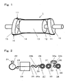
- Fig. 1 is a schematic perspective view showing a mode of a web smoothing roller of the invention.
- An embodiment relates to an apparatus for producing a plastic film roll using a smoothing roller of the invention, and is explained in reference to Figs. 1 through 3.
- Fig. 1 is a schematic perspective view showing the smoothing roller of the invention.
- a smoothing roller 1 comprises a rotary roller main body 12 supported by a shaft 11, a fiber structure 14 covering the outer circumferential surface of the rotary roller main body 12, and expansion/contraction means 15 for expanding and contracting the fiber structure 14 in the rotation center axis direction of the rotary roller main body 12.
- the rotary roller main body 12 can be supported rotatably around the shaft 11, or can also be fixed to and supported by the shaft 11 that can rotate. In either case, in this embodiment, the center axis of the shaft 11 is the rotation center axis.
- the outer circumferential surface 13 of the rotary roller main body 12 and the fiber structure 14 contact each other in such a manner that they can be rotated substantially at the same speed.
- the fiber structure 14 is expanded by the expansion/contraction means 15, and at the top position 17, the fiber structure 14 is contracted by the expansion/contraction means 15. Since the fiber structure 14 is expanded and contracted by the expansion/contraction means 15 in the rotation center axis direction of the rotary roller main body 12, a tension in the width direction is given to the web (not shown in the drawing) moving in contact with the fiber structure 14. As a result, the formation of wrinkles in the web can be prevented, or the wrinkles formed in the web can be smoothed out.
- a stretchable fabric is selected for use from among such fabrics as knitted fabrics, woven fabrics and nonwoven fabrics composed of natural fibers or chemical synthetic fibers.
- Knitted fabrics such as plain-stitched fabrics, rib-stitched fabrics and pearl-stitched fabrics exhibit expandability and contractibility due to the deformation of stitches per se.
- Woven fabrics such as plain-woven fabrics and twill-woven fabrics and nonwoven fabrics are mostly poor in expandability and contractibility, but woven fabrics and nonwoven fabrics respectively composed of elastic yarns or composed of yarns containing them are expandable and contractible.
- the fiber structure 14 covers the outer circumferential surface 13 of the rotary roller main body 12, that is, it is cylindrical, and in this state, the smoothing roller 1 is formed.
- the cylindrical fiber structure 14 is produced by seaming one edge of one or plural fabrics with the other opposite edge by means of bonding, sewing, etc.
- the cylindrical fiber structure 14 covers the rotary roller main body 12 and the expansion/contraction means 15, and both ends of the fiber structure 14 are fixed to the expansion/contraction means 15 of both sides.
- a seamless cylindrical fabric As such a fiber structure, a seamless cylindrical knitted fabric is especially preferred.
- a knitted fabric composed of fibers poor in expandability and contractibility such as polyamide fibers, polyester fibers or acrylic fibers can be used as the fiber structure 14, since it can be expanded and contracted due to the deformation of the stitches per se.
- a knitted fabric composed of elastic yarns or composed of yarns containing them can be more preferably used as the fiber structure 14, since it can be greatly deformed with a small force and since a larger expanding reach can be set without greatly increasing a torque required for rotation.
- this knitted fabric has larger flexibility, it can be more preferably used as the fiber structure 14.
- the elastic yarns for example, processed polytrimethylene glycol yarns and polyurethane fibers can be used.
- polyurethane fibers excellent in elongation and restorability can be suitably used.
- the polyurethane fibers are weak against wear, it is preferred to use them in the form of a multilayered structure yarn such as a single-covered yarn, double-covered yarn, or core spun yarn.
- the covering yarn used as the outermost surface layer of the multilayered structure yarn is a yarn made of a material hard to cause frictional electrification with the web to be produced.
- a covered yarn consisting of a core yarn composed of polyurethane fibers and a covering yarn composed of a material hard to cause frictional electrification with the web to be produced, can prevent the defects of the web brought about by the static electricity due to electrification.
- the web is a polyester film
- the yarns constituting the fiber structure 14 have a fineness of 30 deniers (33 decitexes) to 450 deniers (500 decitexes).
- a fiber structure 14 composed of thin yarns has a problem in view of strength, for example, since it is likely to be broken. Also considering the strength, it is preferred that the yarns constituting the fiber structure 14 have a fineness of 100 deniers (111 decitexes) to 250 deniers (278 decitexes).
- the core yarn has a fineness of 60 deniers (66 decitexes) to 200 deniers (222 decitexes) and that the covering yarn has a fineness of 30 deniers (33 decitexes) to 100 deniers (111 decitexes). In this case, both the yarn strength and the web flaw preventive effect can be satisfied.
- the coefficient of static friction between the web concerned and the fiber structure 14 is higher.
- the coefficient of static friction is from 0.3 to 0.7.
- the material of the outer circumferential surface 13 of the rotary roller main body 12 is not especially limited.
- it can be a metal or a resin or rubber.
- the coefficient of static friction between the fiber structure 14 and the outer circumferential surface 13 is lower.
- the coefficient of static friction is 0.4 or less, the intended function can be achieved without any problem. It is preferred to select the material and surface roughness of the outer circumferential surface 13 so that the coefficient of static friction can be kept in this range.
- a sample sheet as shown in Fig. 8 is used, and a measuring instrument as shown in Fig. 9 is used.
- the rotation center axis direction of the rotary roller main body 12 of the fiber structure 14 covering the outer circumferential surface 13 of the rotary roller main body 12 is defined as the length direction of the fiber structure 14.
- From the fiber structure 14, a 350 mm long and 50 mm wide sample sheet 81 is cut and prepared.
- the length direction of the sample sheet 81 agrees with the length direction of the fober structure 14.
- fixing plates 83a and 83b having holes 82a and 82b formed to hang a weight and a spring balance are attached.
- the fixing plates 83a and 83b are attached to the sample sheet 81, for example, by bolting, uniformly in the width direction, to ensure that they do not slide.
- the sample sheet 81 having the fixing plates 83a and 83b attached to it is set in a measuring instrument, as a test piece 84 for measuring the coefficient of static friction.
- the measuring instrument 91 is shown in Fig. 9.
- the measuring instrument 91 is composed of the rotary roller main body 12 supported without being allowed to rotate, a weight 92 and a spring balance 93.
- the test piece 84 is wound around the outer circumferential surface 13 of the rotary roller main body 12 supported without being allowed to rotate, over 180° in the circumferential direction.
- the weight 92 is attached in the hole 82b of one fixing plate 83b of the test piece 84.
- the weight value of the weight 92 is selected such that the total weight value consisting of the weight value of the fixing plate 83b and the weight value of the weight 92 becomes 100 g.
- the spring balance 93 is attached in the hole 82a of the other fixing plate 83a of the test piece 84.
- the spring balance 93 For measurement, while the bottom of the spring balance 93 is held, the spring balance 93 is sufficiently slowly moved downward as indicated by an arrow 94 at such a speed that it does not affect the test result. The load reached when the test piece 84 begins to move is measured by the spring balance 93.
- the coefficient of static friction is obtained from the following formula (i).
- ⁇ ln ( T 2 / T 1 ) / ⁇
- ⁇ the coefficient of static friction
- T1 is the tension generated by the weight 92 (100 gf (0.98N) in this case)
- T2 is the load measured by the spring balance 93
- ⁇ is the contact angle of the test piece 84 ( ⁇ rad in this case)
- ln is a natural logarithm. Measurement is made at five places excluding both the ends in the rotation center axis direction of the rotary roller main body 12 at every one-sixth length of the outer circumferential surface length of the rotary roller main body 12.
- the load T2 is an average value of the loads obtained by the respective measurement trials.
- the coefficient of static friction between the fiber structure 14 installed around the rotary roller main body 12 and the web is measured also according to the same method as used for measuring the coefficient of static friction between the fiber structure 14 and the outer circumferential surface 13 of the rotary roller main body 12.
- a test piece 104 like the test piece 84 of Fig. 8 is prepared from the web kept in contact with the fiber structure 14 in the web carrying step.
- a measuring instrument 101 is shown in Fig. 10.
- the measuring instrument 101 is composed of the rotary roller main body 12 supported without being allowed to rotate, the fiber structure 14 installed to cover the outer circumferential surface 13 of the rotary roller main body 12, a weight 102 and a spring balance 103.
- the fiber structure 14 is installed around the rotary roller main body 12 such that the maximum expanding position comes at the top in the vertical direction of the rotary roller main body 12, in Fig. 10.
- Measurement is performed using the test piece 104 wound around the fiber structure 14 in Fig. 10.
- the contact angle of the test piece 104 around the fiber structure 14 and the measuring procedure thereafter are the same as the above-mentioned contact angle and measuring procedure explained in reference to Fig. 9.
- a 30 ⁇ m thick polyester film is used.
- a 30 ⁇ m thick polyester film, "Lumirror” S10 type produced by Toray Industries, Inc. is used.
- the expansion/contraction means 15 can be any means, if they have a structure in which the fiber structure 14 can be expanded and contracted in the rotation center axis direction of the rotary roller main body 12.
- the expansion/contraction means can have a mechanism in which plural actuators are disposed on a circumferential orbit and hold both the ends of the fiber structure 14 so that they expand and contract the fiber structure 14 in the rotation center axis direction of the rotary roller main body 12 while they rotate in synchronization with the web carrying speed.
- the expansion/contraction means can also be inclined collars that are provided outside on both sides in the rotation center axis direction and can be rotated around the rotating central axes inclined against the rotation center axis.
- the inclined collars can be preferably used as the expansion/contraction means, since they are simple in structure, do not require power or require only small power, and can be easily synchronously rotated.
- the inclination angle of the inclined collars can be changed as desired.
- the inclination angle can be changed to adequately adjust the smoothing effect in response to the thickness, width and tension of the web to be smoothed for removing wrinkles.
- the fiber structure 14 having contact with a web is used. Since the fiber structure 14 is expandable and contractible on the surface, it touches the web softly, and in the case where any foreign matter intervenes during processing, it can be prevented that the foreign matter is strongly pressed against the web, and the surface of the web is less likely to be damaged.
- the fiber structure 14 can be easily selected to be lighter in weight than other means, and to have moderate friction with the web. In this case, a torque required for rotating the fiber structure is small, and the difference in speed between the fiber structure and the web is less likely to be caused. It, therefore, seldom occurs that the surface of the web is damaged due to slipping.
- the fiber structure 14 generally has air permeability.
- the smoothing roller of the invention is used as a carrier roller in a winding step for production of a plastic film, the grooves formed for air release formed in the carrier roller are not necessary, as the case may be.
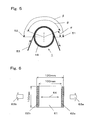
- Fig. 5 is a cross sectional view for explaining the relation between the maximum expanding position of the fiber structure 14 in the smoothing roller 1 and the contact angle of the web 53 around the fiber structure 14.
- the maximum expanding position 51 is the position in the rotating direction at which the fiber structure 14 is expanded to the maximum extent by the expansion/contraction means
- the maximum contracting position 52 is the position in the rotating direction at which the fiber structure 14 is contracted to the maximum extent by the expansion/contraction means 15.
- the contact angle ⁇ of the web 53 is 30° or more. To more highly exhibit the smoothing effect, it is more preferred that the contact angle ⁇ is in a range from 120° to the expanding and contracting angle ⁇ .
- the expanding and contracting angle ⁇ refers to the angle formed among the rotation center axis, the maximum expanding position 51 and the maximum contracting position 52 on a plane perpendicular to the rotating axis.
- the enlarging angle ⁇ is usually 180°, and in the case where actuators are used as the expansion/contraction means 15, the expanding and contracting angle P can be usually any desired angle.
- the installation angle ⁇ refers to the angle formed among the rotation center axis, the maximum expanding position 51 and the point at which the web 53 leaves from the fiber structure 14, on a plane perpendicular to the rotation center axis. In order that the web 53 once expanded cannot be contracted, it is preferred that the installation angle ⁇ is 0° or more, but if the angle is -45° or more, there arises no practical problem in most cases.
- the web smoothing roller of the invention is highly effective in preventing the formation of flaws in a web, it can be preferably used in an apparatus for producing a web severe in quality requirement against flawing, for example, a plastic film used for optical application.
- Fig. 2 is a schematic chart showing a process for producing a general plastic film.
- a molten polymer of a thermoplastic resin is extruded continuously as a sheet from a molding die 21.
- the extruded molten sheet contacts a cooling drum 22, to be cooled into a solidified film 23.
- the film 23 is continuously introduced into a stretcher 24.
- the film 23 is stretched in the machine direction and the transverse direction in the stretcher 24.
- the stretched film 25 is carried by carrier rollers 26a and 26b to a winder 27, and wound as a roll in the winder 27.
- the film wound as a roll forms a film roll (web roll) 28.
- the winder 27 is provided with a rotating pressure contact roller 29 kept in contact with the film roll 28 being formed, at a predetermined pressure.
- the produced film roll 28 can be forwarded as a product in such state. However, if the produced film roll 28 has a large width, it is usually fed to a slitting step as an intermediate product 30.
- the film 31 continuously unwound from the intermediate product 30 is carried by carrier rolls 32a and 32b, to arrive at a slitter 33.
- the film 31 is slit into plural films with a predetermined width.
- the plural films are wound by respective winders 34, to form film rolls (web rolls) 35 as final products.
- Each of the winders 34 is provided with a rotating pressure contact roller 36 kept in contact with the film roll 35 being formed, at a predetermined pressure.
- the web smoothing roller of the invention can be used as required. Furthermore, as each of the rotating pressure contact rollers 29 and 36, the web smoothing roller of the invention can be used as required.
- the film roll 28 or the film roll 35 is fed to a process in which it is treated as predetermined in a reduced pressure atmosphere as produced in a vacuum evaporator.
- the film unwound from the film roll 28 or 35 is carried by carrier rolls and treated as predetermined, then being wound.
- the effect of the entrained air stream entering between the surface of the roller and the film becomes very small compared with a case in an atmosphere.
- the coefficient of friction between the roller and the film becomes large.
- an excessive tension is likely to occur in the width direction of the film, and because of this, the film is likely to be damaged.
- the web smoothing roller of the invention is used as a smoothing means in a process with a reduced pressure atmosphere, the expandability, contractibility and flexibility of the fiber structure allow the slight difference of speeds to be absorbed, and the relative difference of speeds is unlikely to occur. Furthermore, since the excessive tension caused in the width direction of the film is absorbed by the slight deformation of the fiber structure, the undesirable situation as caused by the above-mentioned conventional smoothing means does not occur.
- Fig. 3 is a cross sectional view showing a film winder using a web smoothing roller of the invention as a pressure contact roller.
- a carried plastic film 27 is wound as a film roll (web roll) 38
- the web smoothing roller 1 of the invention comprising the rotary roller main body 12, the fiber structure 14 covering the outer circumferential surface 13 of the rotary roller main body 12 and the expansion/contraction means 15 is kept in pressure contact with the film roll 38, to form the film roll 38.
- the winder 27 or 34 is provided with a pressure contact roller 29 or 36, and where the pressure contact roller 29 or 36 is used to give a contact pressure to the film roll 38 or 35 while the film 25 or 31 is wound in the film winder.
- the web smoothing roller of the invention shown in Fig. 3 is used as the pressure contact roller 29 or 36, the free pass length during which the film having its wrinkles smoothed out runs without being held can be shortened. Therefore, it can be prevented that the film having its wrinkled smoothed out sags again to cause wrinkles to be formed again in the film.
- Fig. 4 is a vertical sectional view showing the smoothing roller 1 of the invention as an example.
- the rotary roller main body 12 is composed of a roller shell 41 made of a carbon fiber reinforced plastic material having a length of 1 m and an outer diameter of 80 mm, annular members 42 attached inside to both the ends of the shell 41 and supporting the shell 41, ball bearings 43 attached inside the annular members 42, and a fixed metallic shaft 11 to which the ball bearings 43 are attached.
- the roller shell 41 is coated, on its surface, with a urethane resin-based paint with a view to preventing contamination and enhancing slipperiness.
- Elastic single-covered yarns (“Lycra" SCY S775D produced by Opelontex Co., Ld.), each consisting of a polyurethane yarn of 70 deniers (78 decitexes) as the core yarn and a polyester yarn of 75 deniers (83 decitexes) as the covering yarn, were used to produce a tubular knitted seamless gray fabric.
- the knitting structure was a rib-stitched fabric.
- the weight of the tubular knitted gray fabric per unit area was 125 g/m 2 .
- the tubular knitted gray fabric was heat-treated in 100°C water for 30 minutes.
- the tubular knitted gray fabric produced like this (hereinafter called the tubular knitted gray fabric of Example 1) was used as the fiber structure 14. Both the ends of the fiber structure 14 were pulled, to install the fiber structure 14 around the outer circumferential surface 13 of the roller shell 41 with a tension of 150 N applied.
- a sample sheet 61 was obtained by cutting from the heat-treated tubular knitted gray fabric.
- the plan view of a sample sheet 61 is shown in Fig. 6.
- the sample sheet 61 was held by vices at both the edges 62a and 62b in the direction along the width, and a tension was applied in the direction indicated by arrows 63a and 63b, to evaluate the above-mentioned stretchability in the length direction (in the direction indicated by arrow 64). All the sample sheets 61 were restored to a dimensional range from 102 mm to 104 mm after release of tension, and confirmed to be strechable.
- a sample sheet 71 was obtained by cutting from the heat-treated tubular knitted gray fabric.
- the plan view of a sample sheet 71 is shown in Fig. 7.
- the sample sheet 71 was held by vices at both the edges 72a and 72b in the direction along the length, and a tension was applied in the direction indicated by arrows 73a and 73b, to evaluate the above-mentioned stretchability in the width direction (direction indicated by arrow 74).
- the sample sheet 71 placed horizontally was held uniformly by vices at the two entire edges extending in the length direction with a distance of 80 mm kept between the vices in the width direction, and a tension was applied in the width direction indicated by the arrows 73a and 73b, to expand the vice-less portion to 88 mm. Subsequently, it was allowed to contract at a speed of 1 mm/second, and the restored length was measured. This measurement was performed with the three sample sheets 71. All the sample sheets 71 were restored to a dimensional range of 82 mm to 84 mm after release of tension, and confirmed to be stretchable.
- the coefficient of static friction between the fiber structure 14 and the surface of the roller shell 41 and the coefficient of static friction between the fiber structure 14 and the polyester film (web) 44 were measured by the methods explained in reference to Figs. 8 and 10.
- Sample sheets were obtained by cutting from a 3 ⁇ m thick film of Polyester Film "Lumirror" C21 type produced by Toray Industries, Inc. Three sample sheets each were prepared for measuring both the coefficients of static friction.
- the coefficient of static friction between the fiber structure 14 and the surface of the roller shell 41 was in a range from 0.15 to 0.24 as a result of measuring the three sample sheets.
- the coefficient of static friction between the fiber structure 14 and the polyester film 44 was in a range from 0.43 to 0.52 as a result of measuring the three sample sheets. It was confirmed that these values were in the above-mentioned suitable ranges of values.
- the expansion/contraction means 15 were composed of inclined annular collars 45 respectively having a rotating central axis inclined against the rotation center axis of the rotary roller main body 12, ball bearings 46 installed inside the inclined collars 45, and inclined collar support members 47 respectively having one of the ball bearings 46 attached at their outer circumferences and respectively attached to the shaft 11 at their inner circumferences.
- the inclined collars 45 were attached to the shaft 11 respectively through one of the ball bearings 46 and one of the inclined collar support members 47, with a clearance of 25 mm kept from the ends of the rotary roller main body 12, outside in the rotation center axis direction of the rotary roller main body 12.
- the clearance refers to the distance between the position of one of the inclined collars 45 closest to the corresponding end of the roller shell 41 and the end of the roller shell 41.
- Both the ends of the fiber structure 14 covering the rotary roller main body 12 were respectively held by the inclined collars 45 of both sides.
- the inclination angle between the rotating central axis of one of the inclined collars 45 and the rotation center axis of the rotary roller main body 12 (hereinafter called the inclination angle of the inclined collars) could be structurally stepwise adjusted.
- the inclination angle of the inclined collars was set at 15°.
- the web smoothing roller 1 manufactured here was used as the smoothing roller (not shown in the drawing) installed immediately before the pressure contract roller 36 of the winder 34 in the slitting step of a biaxially oriented polyester film.
- the smoothing roller 1 used was free in rotation, since the shaft could not be driven to rotate.
- a 0.2 mm thick tape was stuck to the carrier rollers 32a and 32b of the slitting step, to form local level differences, for wrinkling the film 31.
- the film 31 was wound at a winding tension of 30 N/m and a winding speed of 200 m/min.
- the wrinkles in the film roll 35 obtained without applying the web smoothing roller of the invention were compared with those in the film roll 35 obtained with the web smoothing roller applied.
- the smoothing roller 1 of the invention shown in Fig. 1 was manufactured as described for Example 1.
- the detailed structure is as described for Example 1 and as shown in Fig. 4.
- the surface of the roller shell 41 was painted as described for Example 1, it was confirmed that the coating film was worn after a long time of use at both the end portions of the roller shell 41, which were kept in sliding contact with the fiber structure 14. Therefore, in this example, the surface of the roller shell 41 was plated with hard chromium, instead of being coated with the paint.
- the hard chromium plating had high wear resistance compared with the paint in Example 1, and the contamination preventing effect and slipperiness could be maintained for a longer period of time.
- Elastic single covered yarns (“Lycra” SCY S1475D produced by Opelontex Co., Ltd.), each consisting of a polyurethane yarn of 140 deniers (156 decitexes) as the core yarn and a polyester yarn of 75 deniers (83 decitexes) as the covering yarn, were used to produce a tubular knitted seamless gray fabric.
- the knitting structure was a rib-stitched fabric.
- the weight of the tubular knitted gray fabric per unit area was 130 g/m 2 .
- the tubular knitted gray fabric was heat-treated using 100°C water for 30 minutes.
- the tubular knitted gray fabric produced like this (hereinafter called the tubular knitted gray fabric of Example 2) was used as the fiber structure 14. Both the ends of the fiber structure 14 were pulled, and the fiber structure 14 was installed around the outer circumferential surface 13 of the roller shell 41 with a tension of 210 N applied.
- the tubular knitted gray fabric of Example 2 was about 4-fold in the number of alternately repeated expansion and contraction times counted till the fibers were fractured, compared with the tubular knitted grapy fabric of Example 1, in an acceleration test modeling the expansion and contraction of the fiber structure installed around a roller. That is, the number of alternately repeated expansion and contraction times counted till one facture point was confirmed in the fibers of the tubular knitted gray fabric of Example 1 was about 15,000 times, while the corresponding number in the fibers of the tubular knitted gray fabric of Example 2 was about 60,000 times. This means that the tubular knitted gray fabric of Example 2 is longer in useful life.
- the web smoothing roller 1 manufactured in this example was used as the smoothing roller (not shown in the drawing) installed immediately before the pressure contact roller 36 of the winder 34 in the slitting step of a biaxially oriented polyester film.
- the smoothing roller 1 used was free in rotation, since the shaft 11 was not driven to rotate.
- the film pass line was established to keep the contact angle ⁇ of the film 31 at 140°, and the installation angle ⁇ was set at 0°, while the expanding and contracting angle ⁇ was set at 180°.
- the inclination angle of the inclined collars 45 was set at 15°.
- a web smoothing roller 1 constituted as described for Example 1 was used as the smoothing roller (not shown in the drawing) installed immediately before the pressure contract roller 36 of the winder 34 in the slitting step of a biaxially oriented polypropylene film.
- the smoothing roller 1 used was free in rotation, since the shaft 11 was not driven to rotate.
- the film pass line was established to keep the contact angle ⁇ of the film 31 at 140°, and the installation angle ⁇ was set at 0°, while the expanding and contracting angle ⁇ was set at 180°.
- the inclination angle of the inclined collars 45 was set at 8°.
- a web smoothing roller 1 of the invention as shown in Fig. 1 was manufactured.
- the detailed structure was as described for Example 1 and as shown in Fig. 4.
- the rotary roller main body 12 was composed of a roller shell 41 having a length of 2, 800 mm and an outer diameter of 110 mm, made of a carbon fiber reinforced plastic material, annular members 42 installed at both the ends inside the shell 41, to support the shell 41, ball bearings 43 installed inside the annular members 42, and a fixed shaft 11 made of a metal and having the ball bearings 43 attached to it.
- the roller shell 41 was plated, on the surface, with hard chromium in view of the higher wear resistance, better slipperiness and contamination prevention of the surface, etc.
- the fiber structure 14 used was as described for Example 1. Both the ends of the fiber structure 14 were pulled at a tension of 150 N, and the fiber structure was installed around the outer circumferential surface 13 of the roller shell 41.
- the same inclined collars 45 as used in Example 1 were used.
- the inclined collars 45 were attached to the shaft 11 respectively through one of the ball bearings 46 and one of the inclined collar support members 47, with a clearance of 25 mm kept from the ends of the rotary roller main body 12, outside in the rotation center axis direction of the rotary roller main body 12.
- the clearance refers to the distance between the position of one of the inclined collars 45 closest to the corresponding end of the roller shell 41 and the end of the roller shell 41.
- Both the ends of the fiber structure 14 covering the rotary roller main body 12 were respectively held by the inclined collars 45 of both sides.
- the inclination angle between the rotating central axis of one of the inclined collars 45 and the rotation center axis of the rotary roller main body 12 (hereinafter called the inclination angle of the inclined collars) could be structurally stepwise adjusted.
- the inclination angle of the inclined collars was set at 15°.
- the displacement of the fiber structure 14 caused by the expansion/contraction means 15 of both the ends did not propagate to cover the fiber structure 14 as a whole, and only the portions of about 700 mm at both the ends of the fiber structure 14 were expanded and contracted.
- the displacement was effective also for smoothing out the wrinkles in the central portion. That is, it was found that if the web can be sufficiently pulled and expanded at its both ends even though the central portion is not expanded or contracted, the desired smoothing effect can be obtained.
- the web smoothing roller 1 constituted as described above was used as the smoothing roller (not shown in the drawing) installed immediately before the pressure contact roller 29 of the winder 27 in a biaxially oriented polyester film producing apparatus.
- the smoothing roller 1 used was free in rotation, since the shaft was not driven to rotate.
- a 3 ⁇ m thick and 2, 400 mm wide biaxially oriented polyester film (Polyester Film "Lumirror” C10 type produced by Toray Industries, Inc.) was wound for a test.
- As winding conditions a winding tension of 30 N/m and a winding speed of 200 m/min were employed.
- the rejection rate of the film roll 28 due to formed wrinkles was about 30%. In the case where the smoothing roller of this example was used, the rejection rate due to formed wrinkles was 0%. Furthermore, it was also confirmed that the film of the film roll 28 was not flawed.
- a stretchable fiber structure is used as a web smoothing means.
- the fiber structure gives a web wrinkles-smoothing-out action in the width direction of the web running in contact with the fiber structure. Since the wrinkles-smoothing-out action is given by the fiber structure, the action is sufficient for smoothing out wrinkles, but does not substantially flaw the web. Therefore, the web smoothing roller of the invention can be preferably used as a smoothing roller in a process for producing a plastic film. It is especially most suitable as a wrinkles-smoothing-out roller used in a process for producing a web required to be flawless, for example, a plastic film for optical application.
Landscapes
- Registering, Tensioning, Guiding Webs, And Rollers Therefor (AREA)
- Treatment Of Fiber Materials (AREA)
Abstract
Description
- The present invention relates to a web smoothing roller, and an apparatus and a method for producing a web roll.
- In a process for producing a sheet-like material such as a plastic film or paper (hereinafter called a web), various rollers are used for handling the web, for example, for carrying and processing the web. In the handling of the web using rollers, it can happen that the web is flawed or wrinkled. The formation of flaws or wrinkles in the web lowers the yield of the product or lowers the operability of the production process.
- Known means for preventing the formation of wrinkles in the web production process or smoothing out the formed wrinkles include a tenter or cross guider used for pulling both the edges in the width direction of the web toward the outside in the width direction, and an expander roller kept in contact with the overall width of the web. The expander roller comes in either bending type or flat type. A bending type expander roller is a rotating roller having a curved rotating central axis, and it gives a tension in the width direction to the web kept in contact with the rotating roller. A flat type expander roller is a rotating roller having a straight rotating central axis, and has a structure in which the roller shell expands and contracts in the central axis direction during rotation, to give a tension in the width direction to the web kept in contact with the rotating roller.
- A flat type expander roller as a web smoothing roller is disclosed in the
Patent Document 1, the Patent Document 2 or the Patent Document 3. The roller disclosed in thePatent Documents 1, 2 or 3 has many elastic rods extending in the axial direction of the roller in parallel to each other with intervals kept between them in the circumferential direction of the roller. The roller disclosed in the Patent Document 4 has a rubber pipe. - However, with the above-mentioned prior arts, it is difficult to smooth out wrinkles or to prevent flaws in a web required to have higher quality.
- That is, the conventional bending type expander roller has the following problems. A torque necessary for rotation is very large, the driving required for it raises the equipment cost. Structurally an excessive tension in the width direction occurs in the central portion of the web, to distort the web. The effect of smoothing out the wrinkles at the edges of the web is small. A speed difference between a peripheral speed of the roller and a web carrying speed is likely to be large especially at the edges of the web, and slipping is likely to occur at a contact interface between the roller and the web. Since the pass line between front and rear rollers in the central portion of the web is different from that in the edge portions of the web, sagging is likely to occur at the edges of the web.
- The flat type expander roller disclosed in the
Patent Document 1, 2 or 3 is intended to overcome the drawbacks of the bending type expander roller. However, the flat type expander roller has such problems that since the many elastic rods are arranged with intervals kept between them, the expanding action is stepwise and that the roller is likely to be uneven on the outer circumferential surface. Furthermore, in the case where the roller shell is grooved to hold the rods, there arises a problem that the rods are abraded in the grooves, to cause dusting. - To solve these problems, a flat type expander roller having a rubber pipe is disclosed in the Patent document 4. However, also in this method, a torque required for rotation is large. Especially to use this roller for producing a thin film for which a low winding tension is set, this roller must be driven, and the production equipment cost becomes high.
- Moreover, the expander roller of the technique disclosed in the
Patent Document 1, 2 or 3 or the expander roller of the technique disclosed in the Patent Document 4, the outer circumferential surface of the roller is formed of a simply continuous hard material such as a metal or rubber. So, these expander rollers have such problems that the web is likely to be flawed and that the large expansion cannot be achieved.
The Patent Document 1: JP 44-20877 B
The Patent Document 2: US 3,344,493 B
The Patent Document 3: JP 3,028,483 B
The Patent Document 4: JU 57-11966 Y - It is an object of the present invention to provide a web smoothing roller capable of reducing wrinkles of a web in the entire width and decreasing flaw occurrences. It is a further object of the invention to provide a production apparatus for producing a web roll having a reduced wrinkle and flaw. It is yet another object of the invention to provide a production method for producing a web roll having a reduced wrinkle and flaw.
- A web smoothing roller of the invention comprises a rotary roller main body, a fiber structure with strechability, covering the outer peripheral surface of the rotary roller main body, and an expansion/contraction means for expanding /contracting the fiber structure in the direction of the rotation center axis of the rotary roller main body.
- In the web smoothing roller of the invention, it is preferred that the fiber structure is a cylindrical fabric.
- In the web smoothing roller of the invention, it is preferred that the cylindrical fabric is seamless.
- In the web smoothing roller of the invention, it is preferred that the cylindrical fabric is composed of elastic yarns or yarns containing them.
- In the web smoothing roller of the invention, it is preferred that the cylindrical fabric is a knitted fabric.
- In the web smoothing roller of the invention, it is preferred that the knitted fabric is composed of elastic yarns or yarns containing them.
- In the web smoothing roller of the invention, it is preferred that the knitted fabric is seamless.
- In the web smoothing roller of the invention, it is preferred that the expansion/contraction means are provided outside on both sides in the direction of the rotation center axis of the rotary roller main body and each of which comprises an inclined collar being rotaable around a rotating central axis which is inclined against the rotation center axis of the rotary roller main body, and wherein the fiber structure and the inclined collars form an enclosure surrounding the rotary roller main body.
- In the web smoothing roller of the invention, it is preferred that the coefficient of static friction between the fiber structure and a web is from 0.3 to 0.7, and that the coefficient of static friction between the fiber structure and the rotary roller main body is 0.4 or less.
- An apparatus for producing a web roll of the invention, which comprises a web feeding apparatus for continuously feeding a web, a web carrying apparatus for carrying the web continuously fed from the feeding apparatus, and a web winding apparatus for continuously winding as a roll, the web continuously carried by the carrying apparatus, wherein a web smoothing roller of the invention is provided at least at one place in the carrying apparatus.
- The web feeding apparatus for continuously feeding a web in the apparatus for producing a web roll of the invention means a film forming apparatus for continuously forming the web or a web unwinding apparatus for continuously unwinding the web from a web roll.
- In the apparatus for producing a web roll of the invention, it is preferred that the web smoothing roller is disposed in such a manner that it can be kept in pressure contact with a surface of the web roll formed in the web winding apparatus.
- A method for producing a web roll of the invention, which comprises a web feeding step for continuously feeding a web, a web carrying step for continuously carrying the web continuously fed from the feeding step, and a web winding step for continuously winding as a roll, the web continuously carried by the carrying step, wherein a web smoothing roller of the invention is provided at least at one place in the web carrying step.
- The web feeding step for continuously feeding a web in the method for producing a web roll of the invention means a film forming step for continuously forming the web, or a web unwinding step for continuously unwinding the web from a web roll.
- In the method for producing a web roll of the invention, it is preferred that the web is a polyester film.
- The stretchability of the fiber structure in the invention is defined as described below. A fiber structure is cut into a 120 mm long and 120 mm wide square, for use as a sample sheet for evaluating the stretchability. The obtained sample sheet is placed horizontally, and in a state where no tension acts on the sample sheet (non-tensioned state), opposite two sides of the sample sheet are held by vices uniformly over the entire widths in such a manner that they do not slide during the experiment and that the length of the portion not held by the vices becomes 100 mm. In this state, the vices are sufficiently slowly moved in the direction of the two sides opposing each other (tensioning direction) at such a speed that the moving speed does not affect the test result, for tensioning the sample sheet. If the sample sheet is expanded to 110 mm or more without being broken, the vices are then moved in the direction reverse to the tensioning direction at a speed of 1 mm/second after the sample sheet has been expanded up to 110 mm, to release the tension acting on the sample sheet. If the length of the portion not held by the vices in the tensioning direction is restored into a range from 100 mm to 105 mm when the sample sheet is returned to a non-tensioned state, the fiber structure is evaluated to be stretchable in the tensioning direction.
- The sample sheet is prepared in such a manner that when it is used to cover the outer circumferential surface of the rotary roller main body, the direction along the rotation center axis of the rotary roller main body agrees with the length direction of the sample sheet, while the direction along the rotating direction of the rotary roller main body agrees with the width direction of the sample sheet. When the stretchability is observed in the length direction, the fiber structure is evaluated to be stretchable.
- The above-mentioned experiment should be performed in an atmosphere having a temperature of 25°C and a relative humidity of 40% in principle. However, if the atmosphere in which the roller is actually used is obviously different from the above-mentioned atmosphere, the experiment should be made in the temperature, humidity and other environmental conditions equivalent to those of the atmosphere in which the roller is actually used. Furthermore, it can happen that the experiment cannot be performed adequately, for example, since the fiber structure cannot be cut to the above-mentioned dimensions. In such a case, the fiber structure should be cut to such dimensions as to allow the experiment, and the dimension in the tensioning direction should be evaluated in proportion to the above-mentioned value.
- In the case where a fiber structure capable of being expanded and contracted in one direction only is used as the fiber structure of the invention, the direction in which the fiber structure can be expanded and contracted should be made to roughly agree with the direction of the rotation center axis direction of the rotary roller main body. A fiber structure capable of being expanded and contracted in two directions perpendicular to each other is more preferred.
- In the invention, a fiber structure generally refers to a fabric such as a woven fabric, knitted fabric or nonwoven fabric composed of natural fibers or chemical fibers. Any of most knitted fabrics can be used as the fiber structure referred to in the invention. Most of woven fabrics and nonwoven fabrics cannot be expanded or contracted. However, a woven fabric or nonwoven fabric composed of elastic yarns or composed of yarns containing them is expandable and contractible, and may be able to be used as the fiber structure referred to in the invention.
- In the invention, a cylindrical fabric refers to a fabric cylindrical in the inner portion excluding at least both the ends. If the cylindrical fabric is a knitted fabric, the cylindrical knitted fabric can be obtained by forming a sheet-like knitted fabric into a cylinder by sewing or any other method, or can be a seamless cylindrical knitted fabric knitted in a cylindrical form using a knitting machine.
- In the invention, the enclosure refers to a structure comprising one or more members, which generally covers and encloses at least the outer circumferential surface of the rotary roller main body.
- Each of the elastic yarns forming the fiber structure of the invention is defined as described below. A yarn used in the fiber structure is cut to have a length of 120 mm, for use as a sample yarn. The obtained sample yarn is placed in the horizontal direction, and in a state where no tension acts on the sample yarn (non-tensioned state), both the ends of the sample yarn are held by vices in such a manner that the length of the portion not held by the vices becomes 100 mm. In this state, the vices are sufficiently slowly moved in the length direction (tensioning direction) of the sample yarn at such a speed that it does not affect the test result, for tensioning the sample yarn. If the sample yarn is extended to 110 mm or more without being broken, the vices are moved in the direction reverse to the tensioning direction at a speed of 1 mm/second after the yarn has been extended to 110 mm, for releasing the tension acting on the sample yarn. If the length of the portion not held by the vices in the tensioning direction is restored to a range from 100 mm to 105 mm when the yarn is returned to a non-tensioned state, the yarn is evaluated to be an elastic yarn.
- The above-mentioned experiment should be performed in an atmosphere having a temperature of 25°C and a relative humidity of 40% in principle. However, if the atmosphere in which the roller is actually used is obviously different from the above-mentioned atmosphere, the experiment should be made in the temperature, humidity and other environmental conditions equivalent to those of the atmosphere in which the roller is actually used. Furthermore, it can happen that the experiment cannot be performed adequately, for example, since the yarn cannot be cut to the above-mentioned dimension. In such a case, the yarn should be cut to such a dimension as to allow the experiment, and the dimension in the tensioning direction should be evaluated in proportion to the above-mentioned value.
- In the invention, in the case where a cylindrical knitted fabric composed of elastic yarns is used as the fiber structure, even if the difference between the portion in which the length of the fiber structure on the outer circumferential surface of the roller in the rotation center axis direction of the roller is shortest and the portion in which the length is longest, is large, that is, even if the expanding reach of the fiber structure is large, a torque required for rotation can be kept small. Therefore, the rotary roller main body can be rotated only with the frictional force of the web running in contact with the roller, as the case may be. In this case, a larger smoothing effect can be exhibited without spending the enormous cost for large-scale equipment such as driving equipment and the man-hours for working.
- In the invention, since the fiber structure is used on the surface of the roller, the degree of freedom in usable yarns is high. Furthermore, the use of the fiber structure gives, in addition to the web flaw-preventing effect, such an effect that the change in the coefficient of friction due to the temporal deterioration can be lessened compared with the conventional rubber rods. As a result, a virtually equivalent smoothing effect can be maintained for a long period of time.
- In the web smoothing roller of the invention, the fiber structure having strechability is used as means for smoothing out a wrinkle of a web. A function of smoothing out the wrinkle of the web in the widthwise direction of the web running contact with the fiber structure is performed thereby. The function of smoothing out the wrinkle is brought by the fiber structure and therefore it is not substantially affected occurring of flaw on the web while it is sufficient for smoothing the wrinkle of the web.
- Fig. 1 is a schematic perspective view showing a mode of a web smoothing roller of the invention.
- Fig. 2 is a flow chart for explaining a process for producing a general plastic film.
- Fig. 3 is a schematic cross sectional view showing a film winder in the case where a web smoothing roller of the invention is used as a pressure contact roller.
- Fig. 4 is a vertical sectional view showing the web smoothing roller of the invention shown in Fig. 1.
- Fig. 5 is a cross sectional view for explaining the relation between the maximum expanding position and a web contact angle.
- Fig. 6 is a plan view for explaining the method for evaluating a stretchability of a fiber structure in the length direction.
- Fig. 7 is a plan view for explaining the method for evaluating a stretchability of a fiber structure in the width direction.
- Fig. 8 is a plan view for explaining the method for preparing a sample sheet used for measuring a coefficient of friction.
- Fig. 9 is a cross sectional view for explaining the method for measuring a coefficient of friction between a fiber structure and a roller shell.
- Fig. 10 is a cross sectional view for explaining the method for measuring a coefficient of friction between a fiber structure and a web to be smoothed for removing wrinkles.
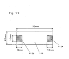
- Fig. 11 is a plan view showing a test piece used for an acceleration test modeling a stretchability of a fiber structure. Meaning of symbols
-
- 1
- smoothing roller
- 11
- shaft
- 12
- rotary roller main body
- 13
- outer circumferential surface
- 14
- fiber structure
- 15
- expansion/contraction means
- 21
- sheet molding die
- 22
- cooling drum
- 23
- film
- 24
- stretcher
- 25
- film
- 26a, 26b
- carrier roller
- 27
- winder
- 28
- film roll (web roll)
- 29
- pressure contact roller
- 30
- intermediate product
- 31
- film
- 32a, 32b
- carrier roll
- 33
- slitter
- 34
- winder
- 35
- film roll (web roll)
- 36
- pressure contact roller
- 37
- plastic film
- 38
- film roll (web roll)
- 41
- roller shell
- 42
- annular member
- 43
- ball bearing
- 44
- polyester film (web)
- 45
- inclined collar
- 45
- ball bearing
- 47
- inclined collar support member
- 51
- maximum expanding position
- 52
- maximum contracting position
- 53
- web
- 61
- sample sheet
- 62a, 62b
- edge portion
- 63a, 63b
- arrow
- 64
- arrow
- 71
- sample sheet
- 72a, 72b
- edge portion
- 73a, 73b
- arrow
- 74
- arrow
- 81
- sample sheet
- 82a,
- 82b hole
- 83a,
- 83b fixing plate
- 84
- test piece
- 91
- measuring instrument
- 92
- weight
- 93
- spring balance
- 101
- measuring instrument
- 102
- weight
- 103
- spring balance
- 104
- test piece
- The invention is described below in more detail using embodiments of the invention. The invention is not limited to or by the embodiments.
- An embodiment relates to an apparatus for producing a plastic film roll using a smoothing roller of the invention, and is explained in reference to Figs. 1 through 3.
- Fig. 1 is a schematic perspective view showing the smoothing roller of the invention. In Fig. 1, a smoothing
roller 1 comprises a rotary rollermain body 12 supported by ashaft 11, afiber structure 14 covering the outer circumferential surface of the rotary rollermain body 12, and expansion/contraction means 15 for expanding and contracting thefiber structure 14 in the rotation center axis direction of the rotary rollermain body 12. The rotary rollermain body 12 can be supported rotatably around theshaft 11, or can also be fixed to and supported by theshaft 11 that can rotate. In either case, in this embodiment, the center axis of theshaft 11 is the rotation center axis. - The outer
circumferential surface 13 of the rotary rollermain body 12 and thefiber structure 14 contact each other in such a manner that they can be rotated substantially at the same speed. At thebottom position 16 of the smoothingroller 1 shown in Fig. 1, thefiber structure 14 is expanded by the expansion/contraction means 15, and at thetop position 17, thefiber structure 14 is contracted by the expansion/contraction means 15. Since thefiber structure 14 is expanded and contracted by the expansion/contraction means 15 in the rotation center axis direction of the rotary rollermain body 12, a tension in the width direction is given to the web (not shown in the drawing) moving in contact with thefiber structure 14. As a result, the formation of wrinkles in the web can be prevented, or the wrinkles formed in the web can be smoothed out. - As the
fiber structure 14, a stretchable fabric is selected for use from among such fabrics as knitted fabrics, woven fabrics and nonwoven fabrics composed of natural fibers or chemical synthetic fibers. Knitted fabrics such as plain-stitched fabrics, rib-stitched fabrics and pearl-stitched fabrics exhibit expandability and contractibility due to the deformation of stitches per se. Woven fabrics such as plain-woven fabrics and twill-woven fabrics and nonwoven fabrics are mostly poor in expandability and contractibility, but woven fabrics and nonwoven fabrics respectively composed of elastic yarns or composed of yarns containing them are expandable and contractible. - The
fiber structure 14 covers the outercircumferential surface 13 of the rotary rollermain body 12, that is, it is cylindrical, and in this state, the smoothingroller 1 is formed. Thecylindrical fiber structure 14 is produced by seaming one edge of one or plural fabrics with the other opposite edge by means of bonding, sewing, etc. Thecylindrical fiber structure 14 covers the rotary rollermain body 12 and the expansion/contraction means 15, and both ends of thefiber structure 14 are fixed to the expansion/contraction means 15 of both sides. - It can happen that the seam of the fabric used as the
cylindrical fiber structure 14 adversely affects the web quality or the smoothing effect. In this case, it is preferred to use a seamless cylindrical fabric as thefiber structure 14. As such a fiber structure, a seamless cylindrical knitted fabric is especially preferred. - A knitted fabric composed of fibers poor in expandability and contractibility such as polyamide fibers, polyester fibers or acrylic fibers can be used as the
fiber structure 14, since it can be expanded and contracted due to the deformation of the stitches per se. However, a knitted fabric composed of elastic yarns or composed of yarns containing them can be more preferably used as thefiber structure 14, since it can be greatly deformed with a small force and since a larger expanding reach can be set without greatly increasing a torque required for rotation. Furthermore, since this knitted fabric has larger flexibility, it can be more preferably used as thefiber structure 14. - As the elastic yarns, for example, processed polytrimethylene glycol yarns and polyurethane fibers can be used. Among them, polyurethane fibers excellent in elongation and restorability can be suitably used. Since the polyurethane fibers are weak against wear, it is preferred to use them in the form of a multilayered structure yarn such as a single-covered yarn, double-covered yarn, or core spun yarn. Above all, it is preferred that the covering yarn used as the outermost surface layer of the multilayered structure yarn is a yarn made of a material hard to cause frictional electrification with the web to be produced. A covered yarn consisting of a core yarn composed of polyurethane fibers and a covering yarn composed of a material hard to cause frictional electrification with the web to be produced, can prevent the defects of the web brought about by the static electricity due to electrification. For example, in the case where the web is a polyester film, it is preferred to use a polyester yarn as the covering yarn.
- It is good that the yarns constituting the
fiber structure 14 have a fineness of 30 deniers (33 decitexes) to 450 deniers (500 decitexes). The inventors found that thinner yarns have a higher effect of preventing the flaws formed in the web. However, afiber structure 14 composed of thin yarns has a problem in view of strength, for example, since it is likely to be broken. Also considering the strength, it is preferred that the yarns constituting thefiber structure 14 have a fineness of 100 deniers (111 decitexes) to 250 deniers (278 decitexes). In the case where the above-mentioned covered yarn is used, it is preferred that the core yarn has a fineness of 60 deniers (66 decitexes) to 200 deniers (222 decitexes) and that the covering yarn has a fineness of 30 deniers (33 decitexes) to 100 deniers (111 decitexes). In this case, both the yarn strength and the web flaw preventive effect can be satisfied. - To enhance the smoothing effect, it is preferred that the coefficient of static friction between the web concerned and the
fiber structure 14 is higher. However, if the coefficient of static friction is too high, the web receives a tension in the width direction more than necessary, and may be flawed. For these reasons, the inventors found that the preferred coefficient of static friction is from 0.3 to 0.7. - The material of the outer
circumferential surface 13 of the rotary rollermain body 12 is not especially limited. For example, it can be a metal or a resin or rubber. However, in order that thefiber structure 14 can be expanded and contracted smoothly in the rotation center axis direction of the rotary rollermain body 12, it is preferred that the coefficient of static friction between thefiber structure 14 and the outercircumferential surface 13 is lower. Usually if the coefficient of static friction is 0.4 or less, the intended function can be achieved without any problem. It is preferred to select the material and surface roughness of the outercircumferential surface 13 so that the coefficient of static friction can be kept in this range. - For measuring the coefficient of static friction between the
fiber structure 14 and the outercircumferential surface 13 of the roller, a sample sheet as shown in Fig. 8 is used, and a measuring instrument as shown in Fig. 9 is used. The rotation center axis direction of the rotary rollermain body 12 of thefiber structure 14 covering the outercircumferential surface 13 of the rotary rollermain body 12 is defined as the length direction of thefiber structure 14. From thefiber structure 14, a 350 mm long and 50 mmwide sample sheet 81 is cut and prepared. The length direction of thesample sheet 81 agrees with the length direction of thefober structure 14. At both ends in the length direction of thesample sheet 81, fixingplates 83b having holes plates sample sheet 81, for example, by bolting, uniformly in the width direction, to ensure that they do not slide. Thesample sheet 81 having the fixingplates test piece 84 for measuring the coefficient of static friction. - The measuring
instrument 91 is shown in Fig. 9. The measuringinstrument 91 is composed of the rotary rollermain body 12 supported without being allowed to rotate, aweight 92 and aspring balance 93. For measuring the coefficient of static friction, thetest piece 84 is wound around the outercircumferential surface 13 of the rotary rollermain body 12 supported without being allowed to rotate, over 180° in the circumferential direction. Theweight 92 is attached in thehole 82b of onefixing plate 83b of thetest piece 84. The weight value of theweight 92 is selected such that the total weight value consisting of the weight value of the fixingplate 83b and the weight value of theweight 92 becomes 100 g. Thespring balance 93 is attached in thehole 82a of the other fixingplate 83a of thetest piece 84. - For measurement, while the bottom of the
spring balance 93 is held, thespring balance 93 is sufficiently slowly moved downward as indicated by anarrow 94 at such a speed that it does not affect the test result. The load reached when thetest piece 84 begins to move is measured by thespring balance 93. The coefficient of static friction is obtained from the following formula (i). -

spring balance 93; φ is the contact angle of the test piece 84 (πrad in this case); and ln is a natural logarithm. Measurement is made at five places excluding both the ends in the rotation center axis direction of the rotary rollermain body 12 at every one-sixth length of the outer circumferential surface length of the rotary rollermain body 12. The load T2 is an average value of the loads obtained by the respective measurement trials. - The coefficient of static friction between the
fiber structure 14 installed around the rotary rollermain body 12 and the web is measured also according to the same method as used for measuring the coefficient of static friction between thefiber structure 14 and the outercircumferential surface 13 of the rotary rollermain body 12. Instead of thesample sheet 81 made from thefiber structure 14 for thetest piece 84, atest piece 104 like thetest piece 84 of Fig. 8 is prepared from the web kept in contact with thefiber structure 14 in the web carrying step. - A measuring
instrument 101 is shown in Fig. 10. The measuringinstrument 101 is composed of the rotary rollermain body 12 supported without being allowed to rotate, thefiber structure 14 installed to cover the outercircumferential surface 13 of the rotary rollermain body 12, aweight 102 and aspring balance 103. Thefiber structure 14 is installed around the rotary rollermain body 12 such that the maximum expanding position comes at the top in the vertical direction of the rotary rollermain body 12, in Fig. 10. - Measurement is performed using the
test piece 104 wound around thefiber structure 14 in Fig. 10. The contact angle of thetest piece 104 around thefiber structure 14 and the measuring procedure thereafter are the same as the above-mentioned contact angle and measuring procedure explained in reference to Fig. 9. When the web to be used is not clear, a 30 µm thick polyester film is used. Particularly, a 30 µm thick polyester film, "Lumirror" S10 type produced by Toray Industries, Inc. is used. - In the above explanation about the measurement of the coefficient of static friction, as shown in Fig. 8, a 350 mm
long sample sheet 81 was used. However, in the case where measurement with this length is difficult, for example, in the case where the diameter of the rotary rollermain body 12 is more than 150 mm, the length can be changed as required. Furthermore, when the weight of thesample sheet 81 is relatively heavy, the weight value of theweight 92 can be modified to such an extent that the effect of the sample sheet becomes negligible. The above-mentioned measurement of the coefficient of static friction is performed in an atmosphere having a temperature of 25°C and a relative humidity of 40% in principle. However, in the case where the atmosphere in which the rotary rollermain body 12 is used is obviously different from the atmosphere, the measurement of the coefficient of static friction is performed under the temperature, humidity and other environmental conditions prevailing in the atmosphere in which the rotary rollermain body 12 is used. - The expansion/contraction means 15 can be any means, if they have a structure in which the
fiber structure 14 can be expanded and contracted in the rotation center axis direction of the rotary rollermain body 12. For example, the expansion/contraction means can have a mechanism in which plural actuators are disposed on a circumferential orbit and hold both the ends of thefiber structure 14 so that they expand and contract thefiber structure 14 in the rotation center axis direction of the rotary rollermain body 12 while they rotate in synchronization with the web carrying speed. The expansion/contraction means can also be inclined collars that are provided outside on both sides in the rotation center axis direction and can be rotated around the rotating central axes inclined against the rotation center axis. The inclined collars can be preferably used as the expansion/contraction means, since they are simple in structure, do not require power or require only small power, and can be easily synchronously rotated. - It is preferred that the inclination angle of the inclined collars can be changed as desired. In this constitution, the inclination angle can be changed to adequately adjust the smoothing effect in response to the thickness, width and tension of the web to be smoothed for removing wrinkles.
- In the invention the
fiber structure 14 having contact with a web is used. Since thefiber structure 14 is expandable and contractible on the surface, it touches the web softly, and in the case where any foreign matter intervenes during processing, it can be prevented that the foreign matter is strongly pressed against the web, and the surface of the web is less likely to be damaged. Thefiber structure 14 can be easily selected to be lighter in weight than other means, and to have moderate friction with the web. In this case, a torque required for rotating the fiber structure is small, and the difference in speed between the fiber structure and the web is less likely to be caused. It, therefore, seldom occurs that the surface of the web is damaged due to slipping. Thefiber structure 14 generally has air permeability. Therefore, even if air comes in between the web such as a plastic film and the roller, it does not stay there but is liable to escape. For this reason, the adhesion between the web and thefiber structure 14 can be highly sustained, while uniform and moderate friction can be stably maintained between them. Because of these properties, in the case where the smoothing roller of the invention is used as a carrier roller in a winding step for production of a plastic film, the grooves formed for air release formed in the carrier roller are not necessary, as the case may be. - Fig. 5 is a cross sectional view for explaining the relation between the maximum expanding position of the
fiber structure 14 in the smoothingroller 1 and the contact angle of theweb 53 around thefiber structure 14. In Fig. 5, the maximum expandingposition 51 is the position in the rotating direction at which thefiber structure 14 is expanded to the maximum extent by the expansion/contraction means 15, and themaximum contracting position 52 is the position in the rotating direction at which thefiber structure 14 is contracted to the maximum extent by the expansion/contraction means 15. It is preferred that the contact angle θ of theweb 53 is 30° or more. To more highly exhibit the smoothing effect, it is more preferred that the contact angle θ is in a range from 120° to the expanding and contracting angle β. The expanding and contracting angle β refers to the angle formed among the rotation center axis, the maximum expandingposition 51 and themaximum contracting position 52 on a plane perpendicular to the rotating axis. In the case where inclined collars are used as the expansion/contraction means 15, the enlarging angle β is usually 180°, and in the case where actuators are used as the expansion/contraction means 15, the expanding and contracting angle P can be usually any desired angle. The installation angle α refers to the angle formed among the rotation center axis, the maximum expandingposition 51 and the point at which theweb 53 leaves from thefiber structure 14, on a plane perpendicular to the rotation center axis. In order that theweb 53 once expanded cannot be contracted, it is preferred that the installation angle α is 0° or more, but if the angle is -45° or more, there arises no practical problem in most cases. - Since the web smoothing roller of the invention is highly effective in preventing the formation of flaws in a web, it can be preferably used in an apparatus for producing a web severe in quality requirement against flawing, for example, a plastic film used for optical application.
- Fig. 2 is a schematic chart showing a process for producing a general plastic film. A molten polymer of a thermoplastic resin is extruded continuously as a sheet from a
molding die 21. The extruded molten sheet contacts acooling drum 22, to be cooled into a solidifiedfilm 23. Thefilm 23 is continuously introduced into astretcher 24. Thefilm 23 is stretched in the machine direction and the transverse direction in thestretcher 24. The stretchedfilm 25 is carried bycarrier rollers winder 27, and wound as a roll in thewinder 27. The film wound as a roll forms a film roll (web roll) 28. Thewinder 27 is provided with a rotatingpressure contact roller 29 kept in contact with thefilm roll 28 being formed, at a predetermined pressure. - The produced
film roll 28 can be forwarded as a product in such state. However, if the producedfilm roll 28 has a large width, it is usually fed to a slitting step as anintermediate product 30. - In the slitting step, the
film 31 continuously unwound from theintermediate product 30 is carried bycarrier rolls slitter 33. In theslitter 33, thefilm 31 is slit into plural films with a predetermined width. The plural films are wound byrespective winders 34, to form film rolls (web rolls) 35 as final products. Each of thewinders 34 is provided with a rotatingpressure contact roller 36 kept in contact with thefilm roll 35 being formed, at a predetermined pressure. - As each of the carrier rolls 26a, 26b, 32a and 32b in the film roll production process shown in Fig. 2, the web smoothing roller of the invention can be used as required. Furthermore, as each of the rotating
pressure contact rollers - It can happen that the
film roll 28 or thefilm roll 35 is fed to a process in which it is treated as predetermined in a reduced pressure atmosphere as produced in a vacuum evaporator. In this process, the film unwound from thefilm roll - On the contrary, in the case where the web smoothing roller of the invention is used as a smoothing means in a process with a reduced pressure atmosphere, the expandability, contractibility and flexibility of the fiber structure allow the slight difference of speeds to be absorbed, and the relative difference of speeds is unlikely to occur. Furthermore, since the excessive tension caused in the width direction of the film is absorbed by the slight deformation of the fiber structure, the undesirable situation as caused by the above-mentioned conventional smoothing means does not occur.
- Fig. 3 is a cross sectional view showing a film winder using a web smoothing roller of the invention as a pressure contact roller. When a carried
plastic film 27 is wound as a film roll (web roll) 38, theweb smoothing roller 1 of the invention comprising the rotary rollermain body 12, thefiber structure 14 covering the outercircumferential surface 13 of the rotary rollermain body 12 and the expansion/contraction means 15 is kept in pressure contact with thefilm roll 38, to form thefilm roll 38. - In the process for producing a plastic film shown in Fig. 2, there can be a case where the
winder pressure contact roller pressure contact roller film roll film pressure contact roller - The
web smoothing roller 1 of the invention shown in Fig. 1 was produced. The detailed structure is shown in Fig. 4. Fig. 4 is a vertical sectional view showing the smoothingroller 1 of the invention as an example. - The rotary roller
main body 12 is composed of aroller shell 41 made of a carbon fiber reinforced plastic material having a length of 1 m and an outer diameter of 80 mm,annular members 42 attached inside to both the ends of theshell 41 and supporting theshell 41,ball bearings 43 attached inside theannular members 42, and a fixedmetallic shaft 11 to which theball bearings 43 are attached. Theroller shell 41 is coated, on its surface, with a urethane resin-based paint with a view to preventing contamination and enhancing slipperiness. - Elastic single-covered yarns ("Lycra" SCY S775D produced by Opelontex Co., Ld.), each consisting of a polyurethane yarn of 70 deniers (78 decitexes) as the core yarn and a polyester yarn of 75 deniers (83 decitexes) as the covering yarn, were used to produce a tubular knitted seamless gray fabric. The knitting structure was a rib-stitched fabric. The weight of the tubular knitted gray fabric per unit area was 125 g/m2. For further enhancing the strechability, the tubular knitted gray fabric was heat-treated in 100°C water for 30 minutes. The tubular knitted gray fabric produced like this (hereinafter called the tubular knitted gray fabric of Example 1) was used as the
fiber structure 14. Both the ends of thefiber structure 14 were pulled, to install thefiber structure 14 around the outercircumferential surface 13 of theroller shell 41 with a tension of 150 N applied. - To measure the stretchability in the length direction of the
fiber structure 14, three 120 mm long and 100 mm wide sample sheets were obtained by cutting from the heat-treated tubular knitted gray fabric. The plan view of asample sheet 61 is shown in Fig. 6. Thesample sheet 61 was held by vices at both theedges arrows sample sheets 61 were restored to a dimensional range from 102 mm to 104 mm after release of tension, and confirmed to be strechable. - To measure the stretchability in the width direction of the
fiber structure 14, three 80 mm long and 100 mm wide sample sheets were obtained by cutting from the heat-treated tubular knitted gray fabric. The plan view of asample sheet 71 is shown in Fig. 7. Thesample sheet 71 was held by vices at both theedges arrows sample sheet 71 placed horizontally was held uniformly by vices at the two entire edges extending in the length direction with a distance of 80 mm kept between the vices in the width direction, and a tension was applied in the width direction indicated by thearrows sample sheets 71. All thesample sheets 71 were restored to a dimensional range of 82 mm to 84 mm after release of tension, and confirmed to be stretchable. - The coefficient of static friction between the
fiber structure 14 and the surface of theroller shell 41 and the coefficient of static friction between thefiber structure 14 and the polyester film (web) 44 were measured by the methods explained in reference to Figs. 8 and 10. Sample sheets were obtained by cutting from a 3 µm thick film of Polyester Film "Lumirror" C21 type produced by Toray Industries, Inc. Three sample sheets each were prepared for measuring both the coefficients of static friction. The coefficient of static friction between thefiber structure 14 and the surface of theroller shell 41 was in a range from 0.15 to 0.24 as a result of measuring the three sample sheets. The coefficient of static friction between thefiber structure 14 and the polyester film 44 was in a range from 0.43 to 0.52 as a result of measuring the three sample sheets. It was confirmed that these values were in the above-mentioned suitable ranges of values. - The expansion/contraction means 15 were composed of inclined
annular collars 45 respectively having a rotating central axis inclined against the rotation center axis of the rotary rollermain body 12,ball bearings 46 installed inside theinclined collars 45, and inclinedcollar support members 47 respectively having one of theball bearings 46 attached at their outer circumferences and respectively attached to theshaft 11 at their inner circumferences. Theinclined collars 45 were attached to theshaft 11 respectively through one of theball bearings 46 and one of the inclinedcollar support members 47, with a clearance of 25 mm kept from the ends of the rotary rollermain body 12, outside in the rotation center axis direction of the rotary rollermain body 12. The clearance refers to the distance between the position of one of theinclined collars 45 closest to the corresponding end of theroller shell 41 and the end of theroller shell 41. - Both the ends of the
fiber structure 14 covering the rotary rollermain body 12 were respectively held by theinclined collars 45 of both sides. The inclination angle between the rotating central axis of one of theinclined collars 45 and the rotation center axis of the rotary roller main body 12 (hereinafter called the inclination angle of the inclined collars) could be structurally stepwise adjusted. In this example, the inclination angle of the inclined collars was set at 15°. - The
web smoothing roller 1 manufactured here was used as the smoothing roller (not shown in the drawing) installed immediately before thepressure contract roller 36 of thewinder 34 in the slitting step of a biaxially oriented polyester film. The smoothingroller 1 used was free in rotation, since the shaft could not be driven to rotate. - When the biaxially oriented
polyester film 31 was carried in contact with thefiber structure 14, thefiber structure 14, theinclined collars 45 and the rotary roller main body 12 (the roller shell 41) were virtually synchronously driven to rotate. The rotation causes thefiber structure 14 to be expanded and contracted in the rotation center axis direction of the rotary rollermain body 12. The expansion and contraction gives a tension in the width direction to thepolyester film 31. The film pass line was established to ensure that the contact angle θ of thefilm 31 became 140°. The installation angle α was 0°, and the expanding and contracting angle β was 180°. - In the slitting step constituted as described above, a 3 µm thick and 600 mm wide biaxially oriented polyester film (Polyester Film "Lumirror" C21 type produced by Toray Industries, Inc.) was wound for a test.
- For the test, a 0.2 mm thick tape was stuck to the
carrier rollers film 31. Thefilm 31 was wound at a winding tension of 30 N/m and a winding speed of 200 m/min. The wrinkles in thefilm roll 35 obtained without applying the web smoothing roller of the invention were compared with those in thefilm roll 35 obtained with the web smoothing roller applied. - As a result of the test, in the case where the smoothing roller was not used, the wrinkles formed on the carrier rolls 32a and 32b remained in the
wound film roll 35, but in the case where the smoothing roller of this example was used, it was confirmed that the wrinkles formed on thecarrier rollers film roll 35. It was also confirmed that the film of thefilm roll 35 was not flawed. - The smoothing
roller 1 of the invention shown in Fig. 1 was manufactured as described for Example 1. The detailed structure is as described for Example 1 and as shown in Fig. 4.
When the surface of theroller shell 41 was painted as described for Example 1, it was confirmed that the coating film was worn after a long time of use at both the end portions of theroller shell 41, which were kept in sliding contact with thefiber structure 14. Therefore, in this example, the surface of theroller shell 41 was plated with hard chromium, instead of being coated with the paint. The hard chromium plating had high wear resistance compared with the paint in Example 1, and the contamination preventing effect and slipperiness could be maintained for a longer period of time. - Elastic single covered yarns ("Lycra" SCY S1475D produced by Opelontex Co., Ltd.), each consisting of a polyurethane yarn of 140 deniers (156 decitexes) as the core yarn and a polyester yarn of 75 deniers (83 decitexes) as the covering yarn, were used to produce a tubular knitted seamless gray fabric. The knitting structure was a rib-stitched fabric. The weight of the tubular knitted gray fabric per unit area was 130 g/m2. For further enhancing the expandability and contractibility, the tubular knitted gray fabric was heat-treated using 100°C water for 30 minutes. The tubular knitted gray fabric produced like this (hereinafter called the tubular knitted gray fabric of Example 2) was used as the
fiber structure 14. Both the ends of thefiber structure 14 were pulled, and thefiber structure 14 was installed around the outercircumferential surface 13 of theroller shell 41 with a tension of 210 N applied. - The tubular knitted gray fabric of Example 2 was about 4-fold in the number of alternately repeated expansion and contraction times counted till the fibers were fractured, compared with the tubular knitted grapy fabric of Example 1, in an acceleration test modeling the expansion and contraction of the fiber structure installed around a roller. That is, the number of alternately repeated expansion and contraction times counted till one facture point was confirmed in the fibers of the tubular knitted gray fabric of Example 1 was about 15,000 times, while the corresponding number in the fibers of the tubular knitted gray fabric of Example 2 was about 60,000 times. This means that the tubular knitted gray fabric of Example 2 is longer in useful life.
- This acceleration test was performed as described below. With the longitudinal direction of the tubular knitted gray fabric as the length direction and with the circumferential direction as the width direction, a 20 mm wide and 70 mm long test piece was cut out without any tension applied. Then, as shown in Fig. 11, the
square regions test piece 111 and by 10 mm in the central portions in the width direction were firmly gripped, and one lateral edge of thetest piece 111 was fixed, while the other lateral edge of thetest piece 111 was vibrated at a frequency of 10 Hz. The stroke range of vibration was set such that the interval between the fixed portions at both the ends became in a range from 50 mm to 190 mm. That is, expansion and contraction was carried out in a range from 1 time to 3.8 times the natural length of tension 0. Thefiber structure 14 installed around theweb smoothing roller 1 of this example was expanded and contracted in a range from 2.0 times to 2.3 times. - The
web smoothing roller 1 manufactured in this example was used as the smoothing roller (not shown in the drawing) installed immediately before thepressure contact roller 36 of thewinder 34 in the slitting step of a biaxially oriented polyester film. The smoothingroller 1 used was free in rotation, since theshaft 11 was not driven to rotate. The film pass line was established to keep the contact angle θ of thefilm 31 at 140°, and the installation angle α was set at 0°, while the expanding and contracting angle β was set at 180°. The inclination angle of theinclined collars 45 was set at 15°. - In the slitting step constituted as described above, a 3 µm thick and 600 mm wide biaxially oriented polyester film (Polyester Film "Lumirror" C21 type produced by Toray Industries, Inc.) was wound for a test, as described for Example 1.
- As a result of the test, in the case where the smoothing roller was not used, the wrinkles formed on the
carrier rollers wound film roll 35, but in the case where the smoothing roller of this example was used, it was confirmed that the wrinkles formed on thecarrier rollers film roll 35 formed. Furthermore, it was also confirmed that the film of thefilm roll 35 was not flawed. - A
web smoothing roller 1 constituted as described for Example 1 was used as the smoothing roller (not shown in the drawing) installed immediately before thepressure contract roller 36 of thewinder 34 in the slitting step of a biaxially oriented polypropylene film. The smoothingroller 1 used was free in rotation, since theshaft 11 was not driven to rotate. The film pass line was established to keep the contact angle θ of thefilm 31 at 140°, and the installation angle α was set at 0°, while the expanding and contracting angle β was set at 180°. The inclination angle of theinclined collars 45 was set at 8°. - In the slitting step constituted as described above, a 3 µm thick and 600 mm wide biaxially oriented polypropylene film (Polypropylene Film "Torayfan" #2172 type produced by Toray Industries, Inc.) was wound for a test as described for Example 1.
- As a result of the test, in the case where the smoothing roller was not used, the wrinkles formed on the
carrier rollers wound film roll 35, but in the case where the smoothing roller of this example was used, it was confirmed that the wrinkles formed on the carrier rolls 32a and 32b were removed in thefilm roll 35 formed. Furthermore, it was also confirmed that the film of thefilm roll 35 was not flawed. - As described for Example 1, a
web smoothing roller 1 of the invention as shown in Fig. 1 was manufactured. The detailed structure was as described for Example 1 and as shown in Fig. 4. The rotary rollermain body 12 was composed of aroller shell 41 having a length of 2, 800 mm and an outer diameter of 110 mm, made of a carbon fiber reinforced plastic material,annular members 42 installed at both the ends inside theshell 41, to support theshell 41,ball bearings 43 installed inside theannular members 42, and a fixedshaft 11 made of a metal and having theball bearings 43 attached to it. Theroller shell 41 was plated, on the surface, with hard chromium in view of the higher wear resistance, better slipperiness and contamination prevention of the surface, etc. - The
fiber structure 14 used was as described for Example 1. Both the ends of thefiber structure 14 were pulled at a tension of 150 N, and the fiber structure was installed around the outercircumferential surface 13 of theroller shell 41. - As the expansion/contraction means 15, the same
inclined collars 45 as used in Example 1 were used. Theinclined collars 45 were attached to theshaft 11 respectively through one of theball bearings 46 and one of the inclinedcollar support members 47, with a clearance of 25 mm kept from the ends of the rotary rollermain body 12, outside in the rotation center axis direction of the rotary rollermain body 12. The clearance refers to the distance between the position of one of theinclined collars 45 closest to the corresponding end of theroller shell 41 and the end of theroller shell 41. - Both the ends of the
fiber structure 14 covering the rotary rollermain body 12 were respectively held by theinclined collars 45 of both sides. The inclination angle between the rotating central axis of one of theinclined collars 45 and the rotation center axis of the rotary roller main body 12 (hereinafter called the inclination angle of the inclined collars) could be structurally stepwise adjusted. In this example, the inclination angle of the inclined collars was set at 15°. - In the
web smoothing roller 1 constituted as described above, the displacement of thefiber structure 14 caused by the expansion/contraction means 15 of both the ends did not propagate to cover thefiber structure 14 as a whole, and only the portions of about 700 mm at both the ends of thefiber structure 14 were expanded and contracted. However, as a result of the experiment, it was confirmed that the displacement was effective also for smoothing out the wrinkles in the central portion. That is, it was found that if the web can be sufficiently pulled and expanded at its both ends even though the central portion is not expanded or contracted, the desired smoothing effect can be obtained. - The
web smoothing roller 1 constituted as described above was used as the smoothing roller (not shown in the drawing) installed immediately before thepressure contact roller 29 of thewinder 27 in a biaxially oriented polyester film producing apparatus. The smoothingroller 1 used was free in rotation, since the shaft was not driven to rotate. - When the biaxially oriented
polyester film 25 was carried in contact with thefiber structure 14, thefiber structure 14, theinclined collars 45 and the rotary roller main body 12 (roller shell 41) were virtually synchronously driven to rotate. This rotation caused thefiber structure 14 to be expanded and contracted in the rotation center axis direction of the rotary rollermain body 12. This expansion and contraction gave a tension in the width direction to the biaxially orientedpolyester film 25. The film pass line was established to keep the contact angle θ of thefilm 25 at 120°, and the installation angle α was set at 0°, while the expanding and contracting angle β was set at 180°. - In the film winding step constituted as described above, a 3 µm thick and 2, 400 mm wide biaxially oriented polyester film (Polyester Film "Lumirror" C10 type produced by Toray Industries, Inc.) was wound for a test. As winding conditions, a winding tension of 30 N/m and a winding speed of 200 m/min were employed.
- In the case where the smoothing
roller 1 of this example was not used, the rejection rate of thefilm roll 28 due to formed wrinkles was about 30%. In the case where the smoothing roller of this example was used, the rejection rate due to formed wrinkles was 0%. Furthermore, it was also confirmed that the film of thefilm roll 28 was not flawed. - In the web smoothing roller of the invention, a stretchable fiber structure is used as a web smoothing means. The fiber structure gives a web wrinkles-smoothing-out action in the width direction of the web running in contact with the fiber structure. Since the wrinkles-smoothing-out action is given by the fiber structure, the action is sufficient for smoothing out wrinkles, but does not substantially flaw the web. Therefore, the web smoothing roller of the invention can be preferably used as a smoothing roller in a process for producing a plastic film. It is especially most suitable as a wrinkles-smoothing-out roller used in a process for producing a web required to be flawless, for example, a plastic film for optical application.
Claims (13)
- A web smoothing roller comprising a rotary roller main body, a fiber structure with strechability, covering the outer peripheral surface of the rotary roller main body, and an expansion/contraction means for expanding/contracting the fiber structure in the direction of the rotation center axis of the rotary roller main body.
- A web smoothing roller according to claim 1, wherein the fiber structure is a cylindrical fabric.
- A web smoothing roller according to claim 2, wherein the cylindrical fabric is seamless.
- A web smoothing roller according to claim 2, wherein the cylindrical fabric is composed of elastic yarns or yarns containing them.
- A web smoothing roller according to claim 2, wherein the cylindrical fabric is a knitted fabric.
- A web smoothing roller according to claim 5, wherein the knitted fabric is composed of elastic yarns or yarns containing them.
- A web smoothing roller according to claim 5, wherein the knitted fabric is seamless.
- A web smoothing roller according to claim 1, wherein the expansion/contraction means are provided outside on both sides in the direction of the rotation center axis of the rotary roller main body and each of which comprises an inclined collar being rotatable around a rotating central axis which is inclined against the rotation center axis of the rotary roller main body, and wherein the fiber structure and the inclined collars form an enclosure surrounding the rotary roller main body.
- A web smoothing roller according to claim 8, wherein the coefficient of static friction between the fiber structure and a web is from 0.3 to 0.7, and the coefficient of static friction between the fiber structure and the rotary roller main body is 0.4 or less.
- An apparatus for producing a web roll, which comprises a web feeding apparatus for continuously feeding a web, a web carrying apparatus for carrying the web continuously fed from the feeding apparatus, and a web winding apparatus for continuously winding as a roll, the web continuously carried by the carrying apparatus, wherein a web smoothing roller as set forth in claim 1 is provided at least at one place in the carrying apparatus.
- An apparatus for producing a web roll according to claim 10, wherein the web smoothing roller is disposed in such a manner that it can be kept in pressure contact with a surface of the web roll formed in the web winding apparatus.
- A method for producing a web roll, which comprises a web feeding step for continuously feeding a web, a web carrying step for continuously carrying the web continuously fed from the feeding step, and a web winding step for continuously winding as a roll, the web continuously carried by the carrying step, wherein a web smoothing roller as set forth in claim 1 is provided at least at one place in the web carrying step.
- A method for producing a web roll according to claim 12, wherein the web is a polyester film.
Applications Claiming Priority (2)
| Application Number | Priority Date | Filing Date | Title |
|---|---|---|---|
| JP2003367172 | 2003-10-28 | ||
| PCT/JP2004/015391 WO2005040018A1 (en) | 2003-10-28 | 2004-10-19 | Web smoothing roller, and web roll producing device and method |
Publications (2)
| Publication Number | Publication Date |
|---|---|
| EP1679275A1 true EP1679275A1 (en) | 2006-07-12 |
| EP1679275A4 EP1679275A4 (en) | 2007-03-07 |
Family
ID=34510285
Family Applications (1)
| Application Number | Title | Priority Date | Filing Date |
|---|---|---|---|
| EP04792560A Withdrawn EP1679275A4 (en) | 2003-10-28 | 2004-10-19 | Web smoothing roller, and web roll producing device and method |
Country Status (5)
| Country | Link |
|---|---|
| US (1) | US20070131809A1 (en) |
| EP (1) | EP1679275A4 (en) |
| KR (1) | KR20060093333A (en) |
| CN (1) | CN1874945A (en) |
| WO (1) | WO2005040018A1 (en) |
Cited By (1)
| Publication number | Priority date | Publication date | Assignee | Title |
|---|---|---|---|---|
| EP2298678A1 (en) * | 2009-09-18 | 2011-03-23 | Reifenhäuser GmbH & Co. Maschinenfabrik | Coiling device |
Families Citing this family (11)
| Publication number | Priority date | Publication date | Assignee | Title |
|---|---|---|---|---|
| KR101132478B1 (en) | 2010-10-29 | 2012-03-30 | 엘지엔시스(주) | Apparatus for transfering media |
| US9138031B2 (en) | 2011-02-16 | 2015-09-22 | 3M Innovative Properties Company | Method of making a mechanical fastening strip and reticulated mechanical fastening strip therefrom |
| DE102012001832B4 (en) * | 2012-02-01 | 2013-08-08 | Hochland Se | Process for processing a flowable food mass |
| JP6138924B2 (en) | 2012-05-16 | 2017-05-31 | スリーエム イノベイティブ プロパティズ カンパニー | Method for manufacturing mechanical fasteners using crown surfaces |
| EP2849601B1 (en) | 2012-05-16 | 2017-08-02 | 3M Innovative Properties Company | Method of making a mechanical fastener using diverging disks |
| US9314962B2 (en) | 2013-05-10 | 2016-04-19 | 3M Innovative Properties Company | Method of separating strands on a stretching surface |
| KR101627190B1 (en) * | 2013-09-30 | 2016-06-03 | 가부시키가이샤 무라타 세이사쿠쇼 | Guide roller, film conveyance apparatus, and sheet forming machine |
| JP6017010B1 (en) | 2015-12-22 | 2016-10-26 | 住友化学株式会社 | Method for producing separator film for lithium ion secondary battery and apparatus for producing separator film for lithium ion secondary battery |
| CA3026223A1 (en) * | 2016-06-03 | 2017-12-07 | Magna Exteriors Inc. | Method to uniformly debundle and evenly distribute high fiber count carbon tow |
| KR102616738B1 (en) * | 2018-05-17 | 2023-12-21 | 주식회사 엘지화학 | Roller for removing wrinkles of film |
| CN113148737B (en) * | 2021-05-18 | 2023-10-31 | 安徽双盈纺织有限公司 | A precise guiding device and guiding method for textile material winding |
Family Cites Families (9)
| Publication number | Priority date | Publication date | Assignee | Title |
|---|---|---|---|---|
| US3278149A (en) * | 1965-02-19 | 1966-10-11 | Aluminum Co Of America | Shelving assembly |
| US3344493A (en) * | 1965-02-19 | 1967-10-03 | Henry E Telgheider | Spreader roll |
| JPS6152662U (en) * | 1984-09-07 | 1986-04-09 | ||
| JPH02152858A (en) * | 1988-12-05 | 1990-06-12 | Sumitomo Bakelite Co Ltd | Film running roller |
| JPH06329309A (en) * | 1993-05-19 | 1994-11-29 | Mitsubishi Heavy Ind Ltd | Winder roll |
| DE9314568U1 (en) * | 1993-09-27 | 1995-02-02 | Eduard Küsters Maschinenfabrik GmbH & Co KG, 47805 Krefeld | roller |
| AU701293B2 (en) * | 1994-04-07 | 1999-01-21 | Pretty Polly Limited | Knitted fabric and method of producing |
| JPH1151041A (en) * | 1997-08-01 | 1999-02-23 | Matsushita Electric Ind Co Ltd | Roller for film transport |
| JP2000118815A (en) * | 1998-10-16 | 2000-04-25 | Kokusai Gijutsu Kaihatsu Kk | Film transfer device |
-
2004
- 2004-10-19 EP EP04792560A patent/EP1679275A4/en not_active Withdrawn
- 2004-10-19 US US10/577,454 patent/US20070131809A1/en not_active Abandoned
- 2004-10-19 CN CNA2004800320907A patent/CN1874945A/en active Pending
- 2004-10-19 KR KR1020067007615A patent/KR20060093333A/en not_active Withdrawn
- 2004-10-19 WO PCT/JP2004/015391 patent/WO2005040018A1/en not_active Ceased
Cited By (2)
| Publication number | Priority date | Publication date | Assignee | Title |
|---|---|---|---|---|
| EP2298678A1 (en) * | 2009-09-18 | 2011-03-23 | Reifenhäuser GmbH & Co. Maschinenfabrik | Coiling device |
| US9187282B2 (en) | 2009-09-18 | 2015-11-17 | Reifenhäuser GmbH & Co. KG Maschinenfabrik | Winding device |
Also Published As
| Publication number | Publication date |
|---|---|
| CN1874945A (en) | 2006-12-06 |
| WO2005040018A1 (en) | 2005-05-06 |
| US20070131809A1 (en) | 2007-06-14 |
| KR20060093333A (en) | 2006-08-24 |
| EP1679275A4 (en) | 2007-03-07 |
Similar Documents
| Publication | Publication Date | Title |
|---|---|---|
| US20070131809A1 (en) | Web smoothing roller, and web roll producing device and method | |
| EP2480472B1 (en) | Web conveyance method and apparatus using same | |
| EP2346668B1 (en) | Film stretcher | |
| JP2006510514A5 (en) | ||
| US20050089640A1 (en) | Method for removing wrinkles, device for removing wrinkles, and coating method | |
| US9751710B2 (en) | Adaptable web spreading device | |
| KR20080087753A (en) | Web Guide Roller, Web Guide Device and Web Guide Method | |
| JP2005154145A (en) | Web wrinkle-stretching roller, film roll manufacturing apparatus using the same, and manufacturing method | |
| WO2015145817A1 (en) | Coating device, coating method, and method for producing resin film having coating film | |
| JP4598820B2 (en) | Web bending apparatus and method | |
| JPH08134645A (en) | Vacuum processing equipment for plastic film | |
| JP2019063983A (en) | Method of manufacturing film roll | |
| US20210107756A1 (en) | Method Of Wrapping A Rolled Roll And Wrapping Device | |
| JP2005230968A (en) | Grooved roller and slitter | |
| JP2610472B2 (en) | Functional roll that can be deformed and transformed | |
| CN215159681U (en) | An anti-wrinkle device for fabric inspection on both sides of the inspection machine | |
| JP2021062974A (en) | Method of manufacturing web | |
| JP2000128404A (en) | Sheet pressure contact device and manufacturing device | |
| JP7243374B2 (en) | film roll | |
| US7182722B2 (en) | Film roll holder for laminators | |
| JP3743522B2 (en) | Belt-shaped photosensitive material conveyance roller | |
| JP2005219847A (en) | Roller for web manufacturing apparatus, and film roll manufacturing apparatus, manufacturing method, and film roll using the same. | |
| WO2018119289A1 (en) | Coating apparatus for moving web | |
| CN120569339A (en) | Web tension adjusting apparatus | |
| US20050218554A1 (en) | Solution casting method |
Legal Events
| Date | Code | Title | Description |
|---|---|---|---|
| PUAI | Public reference made under article 153(3) epc to a published international application that has entered the european phase |
Free format text: ORIGINAL CODE: 0009012 |
|
| 17P | Request for examination filed |
Effective date: 20060323 |
|
| AK | Designated contracting states |
Kind code of ref document: A1 Designated state(s): DE FR GB IT |
|
| DAX | Request for extension of the european patent (deleted) | ||
| RBV | Designated contracting states (corrected) |
Designated state(s): DE FR GB IT |
|
| A4 | Supplementary search report drawn up and despatched |
Effective date: 20070205 |
|
| RIC1 | Information provided on ipc code assigned before grant |
Ipc: B65H 23/025 20060101ALI20070130BHEP Ipc: B65H 27/00 20060101AFI20070130BHEP |
|
| 17Q | First examination report despatched |
Effective date: 20090615 |
|
| STAA | Information on the status of an ep patent application or granted ep patent |
Free format text: STATUS: THE APPLICATION IS DEEMED TO BE WITHDRAWN |
|
| 18D | Application deemed to be withdrawn |
Effective date: 20091027 |