EP1679259A2 - Verfahren zum Einbringen einer Mehrzahl von Raumfahrzeugen individuell auf verschiedenen Umlaufbahnen - Google Patents
Verfahren zum Einbringen einer Mehrzahl von Raumfahrzeugen individuell auf verschiedenen Umlaufbahnen Download PDFInfo
- Publication number
- EP1679259A2 EP1679259A2 EP06000209A EP06000209A EP1679259A2 EP 1679259 A2 EP1679259 A2 EP 1679259A2 EP 06000209 A EP06000209 A EP 06000209A EP 06000209 A EP06000209 A EP 06000209A EP 1679259 A2 EP1679259 A2 EP 1679259A2
- Authority
- EP
- European Patent Office
- Prior art keywords
- earth
- spacecrafts
- swing
- orbit
- maneuver
- Prior art date
- Legal status (The legal status is an assumption and is not a legal conclusion. Google has not performed a legal analysis and makes no representation as to the accuracy of the status listed.)
- Granted
Links
Images



Classifications
-
- B—PERFORMING OPERATIONS; TRANSPORTING
- B64—AIRCRAFT; AVIATION; COSMONAUTICS
- B64G—COSMONAUTICS; VEHICLES OR EQUIPMENT THEREFOR
- B64G1/00—Cosmonautic vehicles
- B64G1/22—Parts of, or equipment specially adapted for fitting in or to, cosmonautic vehicles
- B64G1/24—Guiding or controlling apparatus, e.g. for attitude control
- B64G1/242—Orbits and trajectories
-
- B—PERFORMING OPERATIONS; TRANSPORTING
- B64—AIRCRAFT; AVIATION; COSMONAUTICS
- B64G—COSMONAUTICS; VEHICLES OR EQUIPMENT THEREFOR
- B64G1/00—Cosmonautic vehicles
- B64G1/10—Artificial satellites; Systems of such satellites; Interplanetary vehicles
- B64G1/1085—Swarms and constellations
-
- B—PERFORMING OPERATIONS; TRANSPORTING
- B64—AIRCRAFT; AVIATION; COSMONAUTICS
- B64G—COSMONAUTICS; VEHICLES OR EQUIPMENT THEREFOR
- B64G1/00—Cosmonautic vehicles
- B64G1/22—Parts of, or equipment specially adapted for fitting in or to, cosmonautic vehicles
- B64G1/24—Guiding or controlling apparatus, e.g. for attitude control
- B64G1/242—Orbits and trajectories
- B64G1/2427—Transfer orbits
Definitions
- the present invention relates to a space system including a single assist module coupled to a plurality of space-vehicles or spacecrafts, and more particularly to a method of launching the single assist module together with the plurality of spacecrafts and then controllably guiding the spacecrafts into different desired orbits, such as interplanetary orbits, individually.
- a problem to be solved by the present invention is a difficulty in, after launching a plurality of spacecrafts all together, injecting them into different orbits, such as circum-earth orbits or interplanetary orbits, individually.
- a conventional solution of this problem has involved the need for equipping each of the spacecrafts with its own rocket (launch vehicle), and inevitably led to significant increase in cost.
- it has been essentially required to equip each of the spacecrafts with its own launching means.
- such an operation has been regarded as unrealizable because of extremely poor efficiency and unacceptable cost performance.
- Patent Publication 1 discloses a method of launching a plurality of space satellites, particularly, a technique of reducing a fuel consumption in an orbit-control propulsion system (orbital maneuvering system) for orbital transfer.
- the technique disclosed in the Patent Publication 1 is not designed to change an inclination of a circum-earth orbit.
- the present invention is premised on a system capable of changing an orbital element by means of a perturbation effect arising from a gravitational field of the earth.
- the technique disclosed in the Patent Publication 1 is not originally designed to inject a plurality of spacecrafts into different interplanetary orbits individually.
- the present invention provides a method for injecting a plurality of spacecrafts escaping from a gravitational sphere of the earth, into at least two different orbits in a single launch and then loosing the plurality of spacecrafts, respectively, toward different targets.
- the method comprises the steps of; injecting the plurality of spacecrafts into an interplanetary orbit having a periodicity synchronous with the earth's revolution period, in a state of being coupled to a single assist module for assisting a space flight thereof; and performing a swing-by maneuver relative to the earth, wherein, in advance of executing the swing-by maneuver, the orbit of the assist module is changed in a sequential order with respect to each of the plurality of spacecrafts.
- the step of performing a swing-by maneuver relative to the earth includes changing the orbit of the assist module in a sequential order with respect to each of the plurality of spacecrafts a half month to several days before executing the swing-by maneuver, so as to control a closest-approach point to the earth for each of the spacecrafts in conformity to a target orbit for each of the spacecrafts, and then separating each of the spacecrafts from the assist module in a sequential order.
- the method includes the step of, when each of the spacecrafts after being separated from the assist module in the swing-by step passes through the closest-approach point to the earth, subjecting the spacecraft to an acceleration/deceleration control unique to the spacecraft.
- an established orbit will be an elliptical orbit around the earth.
- the interplanetary orbit having a periodicity synchronous with the earth's revolution period is one selected from the group consisting of a plurality of singular trajectories or orbits around the sun each of which has a synchronous period including six months, one year, an integer number of years and a period having a rational or irrational number ratio with respect to the earth's revolution period, and a property of being able to re-encounter with the earth regardless of a velocity of escape from the earth.
- singular trajectory means an orbit around the sun which has an irrational period of about 1.4 years, 2.4 years, -----, and a property of being able to re-encounter with the earth regardless of a velocity of escape from the earth.
- the step of performing a swing-by maneuver relative to the earth includes, after executing the swing-by maneuver, further repeatedly revolving the assist module around the sun, and executing an additional swing-by maneuver similar to the swing-by maneuver as a backup action for loosing the spacecrafts, respectively, toward specific interplanetary orbits.
- the step of performing a swing-by maneuver relative to the earth may include a deceleration maneuver for allowing the spacecrafts to be captured by the earth's gravitational sphere and injected into at least two different elliptical orbits around the earth.
- the at least two different elliptical orbits may be selected from the group consisting of a combination of at least two elliptical orbits each having a different inclination, a combination of at least two direct and retrograde elliptical orbits, and a combination of at least two polar and low-inclination elliptical orbits.
- the swing-by maneuver relative to the earth may be performed by use of the gravity of a planet other than the earth.
- the step of injecting the plurality of spacecrafts into an interplanetary orbit having a periodicity synchronous with the earth's revolution period may be initiated in a state when the plurality of spacecrafts coupled to the assist module makes a flight in a circumterrestrial space or an interplanetary space.
- the method of the present invention makes it possible to inject a plurality of spacecrafts, i.e., at least two spacecrafts or, if needed, dozens of spacecrafts, into different interplanetary orbits or different orbits around the earth (circum-earth orbits) individually in a single launch using the single assist module.
- the method of the present invention makes it possible to selectively determine a plurality of different directions escaping from the earth, in a single launch and loose a plurality of planetary exploration spacecrafts toward different astronomical objects individually.
- an escape direction from an orbit of a spacecraft mounted on the rocket or the like is limited to only an in-plane direction of a parking orbit of the rocket or the like.
- the method of the present invention can completely remove this restriction.
- the method of the present invention makes it possible to loose dozens of payloads toward different targets individually.
- the method of the present invention can be widely applied to an observation mission of a small celestial body, such as near-earth miniplanet or minicomet.
- the spacecraft is a space satellite
- a plurality of launches have been required to inject a plurality of satellites into different orbits, particularly, largely different in inclination.
- the method of the present invention makes it possible to inject a plurality of satellites into direct and retrograde elliptical orbits, or polar and low-inclination elliptical orbits in a single launch.
- the method of the present invention can be expected to have wide applications to a satellite system (constellation) achieving its function using a navigation, communication or global positioning satellite.
- All spacecrafts to be injected into different orbits are coupled to an assist base module, and injected into a parking orbit, which is an interplanetary orbit having the shortest periodicity synchronous with the earth's revolution period, in a single launch.
- the assist base module plays two rolls in correcting an initial orbit-injection error and in finely changing its own orbit in advance of execution of a swing-by maneuver relative to the earth (Earth swing-by) and then separating each of the mounted spacecrafts therefrom in a sequential order.
- This embodiment is a method for injecting four spacecrafts consisting of a first spacecrafts 1, a second spacecraft 2, a third spacecraft 3 and a fourth spacecraft 4, into four different target interplanetary orbits in a single launch using a single assist module 5 for the purpose of exploration of four different miniplanets (name: 1999 NAS, 2002 AY1, 2003 YN1 and 2004 MO3).
- FIG. 1 shows the four spacecrafts 1, 2, 3, 4 mounted on the assist module 5.
- the four cylindrical-shaped spacecrafts are mounted on a circular top surface of the cylindrical-shaped assist module 5 in a concentric arrangement.
- the assist module 5 is provided with a plurality of attitude-control thrusters 6 at a side surface thereof.
- the assist module 5 is further provided with a propulsion thruster (not shown) adapted to emit a jet in an axial direction of the spacecrafts, at a bottom surface thereof.
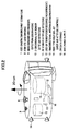
- FIG. 2 schematically shows one example of the spacecraft to injected into a given target interplanetary orbit in a state of being mounted on the assist module.
- the spacecraft in this example may be used as each of the first through the fourth spacecrafts 1 to 4 and is provided with a CCD camera 7 for imaging and orbit estimation, a fish-eye lens 8 for imaging, a near-infrared spectroscope 9 for spectrum observation, a 2-dimensional sun sensor 10 for attitude detection, an RF sensor 11 for attitude detection, an ultra-stable oscillator (USO) or transponder 12 for distance measurement, an omnidirectional antenna 13 for communication, a new-type cold gas jet 14 for orbit and attitude control, a data recorder (DR) 15 for data storage and a battery (BAT) 16 for power supply.
- the assist module 5 may be similar in structure to the spacecraft illustrated in Fig. 2.
- a plurality of spacecrafts coupled to a single assist module is injected into an interplanetary orbit having a periodicity synchronous with the earth's revolution period as described above, and then a maneuver for allowing the assist module with the spacecrafts to re-encounter with the earth and pass through the vicinity of the earth (hereinafter referred to as "Earth swing-by") is performed.
- the assist module appropriately performs an orbital change maneuver and a separation maneuver for each of the spacecrafts in a sequential order. Through these maneuvers, a closest-approach point to the earth is changed for each of the spacecrafts so as to drastically change a subsequent orbital element for each of the spacecrafts.
- FIG. 3 shows a concept of this orbit injection represented using an inertial coordinate-system. While FIG. 3 shows one example where a synchronous period is one year, various synchronous periods may be selected.
- FIG. 4 shows this concept represented using a rotating coordinate system wherein a line between the sun and the earth is fixed.
- FIGS. 5 and 6 show a plurality of orbits during the Earth swing-by.
- FIG. 5 shows a maneuver in an orbital plane.
- FIG. 6 shows one example a plurality of different orbits to be achieved by combining a plurality of maneuvers in an out-of-plane direction of an orbit.
- the assist module takes a sufficient time to determine a target orbit for each of the spacecrafts with a high degree of accuracy until a half month to several days before a closest-approach time in the Earth swing-by. Based on the determined orbit, the assist module makes an orbit correction of about several m/sec in a sequential order, and then separates the spacecrafts therefrom in a sequential order. In this process, an inertia navigation is performed based on an accelerometer mounted in the assist module and information about attitude to adequately control an orbital quantity.
- an escape direction can be changed in an angle of one radian by changing the closest-approach point in a distance of about 10,000 km during the Earth swing-by.
- the level of the orbit correction to be performed by the assist module is no more than 1 to 10 m/sec although it is varied depending on the timing of implementation thereof. If all directions of a plurality of escape orbits can be assured within several degrees, the orbit correction to be performed by the assist module is about 1 m/sec.
- While the orbit correction to be performed by the assist module can include an operational error, the level of the error is about 1 to 2 cm/sec in a practical sense and in an empiric sense, and an orbit correction after the Earth swing-by can be confined to 1 to 10 m/sec.
- These control quantities are determined with respect to each target interplanetary orbit, and the assist module is controlled based on the determined control quantities at a given timing according to a remote command from the earth.
- FIG. 7 illustrates one example of a synchronous orbit having an encounter period of one year, for use in injecting the four spacecrafts 1, 2, 3, 4 into four different target interplanetary orbits in a single launch using the single assist module 5.
- the assist module 5 mounting the four spacecrafts 1, 2, 3, 4 is injected into a synchronous orbit to perform the Earth swing-by one year from the launch.
- FIG. 8 shows a time of separating each of the spacecrafts 1, 2, 3, 4 from the assist module 5 and a control quantity of the separation maneuver. That is, FIG. 8 shows a control quantity and time of a pre-Earth swing-by targeting.
- the pre-Earth swing-by targeting in this example is performed on a target plane (B-plane), and the four spacecrafts 1, 2, 3, 6 are separated at the following times and in the following control quantities:
- FIG. 9 shows a state of a target miniplanet-flyby (passing near to each target miniplanet) after the Earth swing-by in each of the spacecrafts 1, 2, 3, 4 separated in the above process.
- the spacecrafts 1 to 4 fly, respectively, in different orbits and toward different target miniplanets.
- a relationship of target miniplanet-flyby times of the spacecrafts and the corresponding target miniplanets is as follows:
- the relative velocity/sun angle is an angle between a sun direction and a vector direction viewed from each of the spacecrafts.
- the international acquisition of a patent right on this invention will bring about positive effects in achievement of international cooperation-based missions.
- the interplanetary-orbit injection method of the present invention is strongly desired by planetary science laboratories in many countries.
- the present invention would contribute to space science, particularly, planetary science research.
Landscapes
- Engineering & Computer Science (AREA)
- Remote Sensing (AREA)
- Aviation & Aerospace Engineering (AREA)
- Chemical & Material Sciences (AREA)
- Combustion & Propulsion (AREA)
- Radar, Positioning & Navigation (AREA)
- Physics & Mathematics (AREA)
- Astronomy & Astrophysics (AREA)
- General Physics & Mathematics (AREA)
- Control Of Position, Course, Altitude, Or Attitude Of Moving Bodies (AREA)
- Navigation (AREA)
Applications Claiming Priority (1)
| Application Number | Priority Date | Filing Date | Title |
|---|---|---|---|
| JP2005001759A JP4097086B2 (ja) | 2005-01-06 | 2005-01-06 | 複数の宇宙機を異なる軌道に投入する方法 |
Publications (3)
| Publication Number | Publication Date |
|---|---|
| EP1679259A2 true EP1679259A2 (de) | 2006-07-12 |
| EP1679259A3 EP1679259A3 (de) | 2015-03-11 |
| EP1679259B1 EP1679259B1 (de) | 2016-07-20 |
Family
ID=36216976
Family Applications (1)
| Application Number | Title | Priority Date | Filing Date |
|---|---|---|---|
| EP06000209.4A Expired - Lifetime EP1679259B1 (de) | 2005-01-06 | 2006-01-05 | Verfahren zum individuellen Einbringen einer Mehrzahl von Raumfahrzeugen auf verschiedenen Umlaufbahnen |
Country Status (3)
| Country | Link |
|---|---|
| US (1) | US7747361B2 (de) |
| EP (1) | EP1679259B1 (de) |
| JP (1) | JP4097086B2 (de) |
Cited By (4)
| Publication number | Priority date | Publication date | Assignee | Title |
|---|---|---|---|---|
| CN104608940A (zh) * | 2014-12-22 | 2015-05-13 | 汪宇 | 引力场曲率驱动引擎的方法 |
| CN109238287A (zh) * | 2018-09-06 | 2019-01-18 | 中国人民解放军国防科技大学 | 一种航天器逃逸路径规划方法及系统 |
| CN111504330A (zh) * | 2020-05-07 | 2020-08-07 | 中国人民解放军63768部队 | 一种基于实测数据的低轨航天器准实时轨道机动检测方法 |
| CN118343315A (zh) * | 2024-04-16 | 2024-07-16 | 西北工业大学 | 基于空间绳网协同捕获的动态轨道博弈优化方法及系统 |
Families Citing this family (8)
| Publication number | Priority date | Publication date | Assignee | Title |
|---|---|---|---|---|
| RU2512067C1 (ru) * | 2012-12-25 | 2014-04-10 | Александр Вадимович Марков | Способ увеличения орбиты земли в солнечной системе |
| CN104252132A (zh) * | 2013-06-27 | 2014-12-31 | 上海新跃仪表厂 | 基于自适应遗传算法的行星际轨道控制优化方法 |
| KR102186085B1 (ko) * | 2014-03-07 | 2020-12-04 | 한국전자통신연구원 | 우주 물체 폐기 장치 및 우주 물체 폐기 방법 |
| JP6291471B2 (ja) * | 2015-12-21 | 2018-03-14 | 株式会社Ihiエアロスペース | 衛星コンステレーションの形成方法 |
| US11673694B2 (en) * | 2017-12-01 | 2023-06-13 | D-ORBIT S.p.A. | Method of releasing artificial satellites in earth's orbit |
| US11505338B2 (en) * | 2019-02-22 | 2022-11-22 | The Boeing Company | Systems and methods for launching a plurality of spacecraft |
| CN110673486B (zh) * | 2019-10-22 | 2021-03-09 | 北京航空航天大学 | 一种基于动态博弈理论的多航天器追逃控制方法 |
| CN114895692B (zh) * | 2022-04-12 | 2025-02-11 | 西北工业大学 | 一种大型航天器在轨装配的姿轨振一体化建模方法 |
Citations (1)
| Publication number | Priority date | Publication date | Assignee | Title |
|---|---|---|---|---|
| JPH07187091A (ja) | 1993-12-28 | 1995-07-25 | Natl Space Dev Agency Japan<Nasda> | 複数の人工衛星の打ち上げ方法 |
Family Cites Families (10)
| Publication number | Priority date | Publication date | Assignee | Title |
|---|---|---|---|---|
| US4854526A (en) * | 1987-08-10 | 1989-08-08 | Hughes Aircraft Company | Spacecraft design enabling the compact nesting of multiple spacecraft in the launch vehicle |
| US5393017A (en) * | 1993-01-25 | 1995-02-28 | Lockheed Missiles & Space Company, Inc. | Technique for dispensing earth satellites into multi-planar orbits |
| US5350137A (en) * | 1993-05-19 | 1994-09-27 | General Dynamics Corporation Space Systems Division | Multiple application paraboloid spacecraft structure |
| US5566909A (en) * | 1993-09-08 | 1996-10-22 | Hughes Aircraft Company | System and method for deploying multiple probes |
| IT1261940B (it) * | 1993-09-24 | 1996-06-04 | Alenia Spazio Spa | Sistema per telecomunicazioni e telerilevamento via satellite basato sull'uso di orbite eliosincrone ellittiche di breve periodo. |
| FR2757824B1 (fr) * | 1996-12-31 | 1999-03-26 | Europ Propulsion | Procede et systeme de lancement de satellites sur des orbites non coplanaires en utilisant l'assistance gravitationnelle lunaire |
| DE19856670B4 (de) * | 1998-12-09 | 2004-12-02 | Eads Space Transportation Gmbh | Vorrichtung zum Aussetzen von Satelliten |
| EP1257470B1 (de) * | 2000-02-23 | 2004-06-09 | Centre National D'etudes Spatiales | Verfahren zur fertigung eines sockels für die halterung eines satelliten auf einer transportplattform für mehrere satelliten |
| US7219858B2 (en) * | 2004-07-06 | 2007-05-22 | The Johns Hopkins University | Method for deploying multiple spacecraft |
| US7631839B1 (en) * | 2004-08-20 | 2009-12-15 | Lockheed Martin Corporation | Enhanced multiple instrument distributed aperture sensor |
-
2005
- 2005-01-06 JP JP2005001759A patent/JP4097086B2/ja not_active Expired - Fee Related
-
2006
- 2006-01-05 EP EP06000209.4A patent/EP1679259B1/de not_active Expired - Lifetime
- 2006-01-06 US US11/326,440 patent/US7747361B2/en not_active Expired - Fee Related
Patent Citations (1)
| Publication number | Priority date | Publication date | Assignee | Title |
|---|---|---|---|---|
| JPH07187091A (ja) | 1993-12-28 | 1995-07-25 | Natl Space Dev Agency Japan<Nasda> | 複数の人工衛星の打ち上げ方法 |
Cited By (5)
| Publication number | Priority date | Publication date | Assignee | Title |
|---|---|---|---|---|
| CN104608940A (zh) * | 2014-12-22 | 2015-05-13 | 汪宇 | 引力场曲率驱动引擎的方法 |
| CN109238287A (zh) * | 2018-09-06 | 2019-01-18 | 中国人民解放军国防科技大学 | 一种航天器逃逸路径规划方法及系统 |
| CN109238287B (zh) * | 2018-09-06 | 2020-11-10 | 中国人民解放军国防科技大学 | 一种航天器逃逸路径规划方法及系统 |
| CN111504330A (zh) * | 2020-05-07 | 2020-08-07 | 中国人民解放军63768部队 | 一种基于实测数据的低轨航天器准实时轨道机动检测方法 |
| CN118343315A (zh) * | 2024-04-16 | 2024-07-16 | 西北工业大学 | 基于空间绳网协同捕获的动态轨道博弈优化方法及系统 |
Also Published As
| Publication number | Publication date |
|---|---|
| US7747361B2 (en) | 2010-06-29 |
| US20060241824A1 (en) | 2006-10-26 |
| JP4097086B2 (ja) | 2008-06-04 |
| EP1679259A3 (de) | 2015-03-11 |
| JP2006188149A (ja) | 2006-07-20 |
| EP1679259B1 (de) | 2016-07-20 |
Similar Documents
| Publication | Publication Date | Title |
|---|---|---|
| JP6998799B2 (ja) | 可変なスラスター制御を用いた軌道上サービスを提供するためのサービス衛星 | |
| ES2345494T3 (es) | Aparato para un vehiculo espacial geosincrono para extension de la vida util. | |
| EP3395693B1 (de) | Verfahren zur formung einer satellitenkonstellation und formvorrichtung | |
| EP1679259B1 (de) | Verfahren zum individuellen Einbringen einer Mehrzahl von Raumfahrzeugen auf verschiedenen Umlaufbahnen | |
| WO2022153619A1 (en) | Method and system for multi-object space debris removal | |
| Berlin | The geostationary applications satellite | |
| Underwood et al. | In-orbit results from the SNAP-1 nanosatellite and its future potential | |
| O'Neil et al. | The Mars sample return project | |
| US6464174B1 (en) | Round-trip orbital operation of a spacecraft | |
| Inatani et al. | SS-520 Nano satellite launcher and its flight result | |
| Johnson et al. | Near earth asteroid scout-mission update | |
| Rudolph | Lisa pathfinder launch and early operations phase-in-orbit experience | |
| Panetta et al. | NASA-GSFC nano-satellite technology development | |
| Hine et al. | The lunar atmosphere and dust environment explorer mission | |
| Atkins et al. | Solar electric propulsion combined with earth gravity assist-A newpotential for planetary exploration | |
| Barnhart et al. | XSS-10 micro-satellite demonstration | |
| Schmidt et al. | ESA's Mars express mission-Europe on its way to Mars | |
| Shotwell et al. | A Mars Ascent Vehicle for potential mars sample return | |
| Gershman et al. | From GTO to the Planets | |
| Pranajaya et al. | Generic nanosatellite bus for responsive mission | |
| Uesugi et al. | MUSES-A double lunar swingby mission | |
| Kaneko et al. | The SELENE project and the following lunar mission | |
| O’Neil | The Galileo Spacecraft Architecture | |
| Dillman et al. | Planned flight of the terrestrial hiad orbital reentry (thor) | |
| Spremo et al. | The Lunar Atmosphere and Dust Environment Explorer (LADEE) Mission |
Legal Events
| Date | Code | Title | Description |
|---|---|---|---|
| PUAI | Public reference made under article 153(3) epc to a published international application that has entered the european phase |
Free format text: ORIGINAL CODE: 0009012 |
|
| AK | Designated contracting states |
Kind code of ref document: A2 Designated state(s): AT BE BG CH CY CZ DE DK EE ES FI FR GB GR HU IE IS IT LI LT LU LV MC NL PL PT RO SE SI SK TR |
|
| AX | Request for extension of the european patent |
Extension state: AL BA HR MK YU |
|
| PUAL | Search report despatched |
Free format text: ORIGINAL CODE: 0009013 |
|
| AK | Designated contracting states |
Kind code of ref document: A3 Designated state(s): AT BE BG CH CY CZ DE DK EE ES FI FR GB GR HU IE IS IT LI LT LU LV MC NL PL PT RO SE SI SK TR |
|
| AX | Request for extension of the european patent |
Extension state: AL BA HR MK YU |
|
| RIC1 | Information provided on ipc code assigned before grant |
Ipc: B64G 1/00 20060101AFI20150205BHEP Ipc: B64G 1/10 20060101ALI20150205BHEP Ipc: B64G 1/24 20060101ALI20150205BHEP |
|
| 17P | Request for examination filed |
Effective date: 20150828 |
|
| RBV | Designated contracting states (corrected) |
Designated state(s): AT BE BG CH CY CZ DE DK EE ES FI FR GB GR HU IE IS IT LI LT LU LV MC NL PL PT RO SE SI SK TR |
|
| AKX | Designation fees paid |
Designated state(s): DE FR GB |
|
| AXX | Extension fees paid |
Extension state: HR Extension state: MK Extension state: AL Extension state: BA Extension state: YU |
|
| RAP1 | Party data changed (applicant data changed or rights of an application transferred) |
Owner name: KAWAGUCHI, JUNICHIRO Owner name: NEC SPACE TECHNOLOGIES, LTD. |
|
| GRAP | Despatch of communication of intention to grant a patent |
Free format text: ORIGINAL CODE: EPIDOSNIGR1 |
|
| INTG | Intention to grant announced |
Effective date: 20160210 |
|
| GRAS | Grant fee paid |
Free format text: ORIGINAL CODE: EPIDOSNIGR3 |
|
| GRAA | (expected) grant |
Free format text: ORIGINAL CODE: 0009210 |
|
| AK | Designated contracting states |
Kind code of ref document: B1 Designated state(s): DE FR GB |
|
| REG | Reference to a national code |
Ref country code: GB Ref legal event code: FG4D |
|
| REG | Reference to a national code |
Ref country code: DE Ref legal event code: R096 Ref document number: 602006049638 Country of ref document: DE |
|
| REG | Reference to a national code |
Ref country code: FR Ref legal event code: PLFP Year of fee payment: 12 |
|
| REG | Reference to a national code |
Ref country code: DE Ref legal event code: R097 Ref document number: 602006049638 Country of ref document: DE |
|
| PLBE | No opposition filed within time limit |
Free format text: ORIGINAL CODE: 0009261 |
|
| STAA | Information on the status of an ep patent application or granted ep patent |
Free format text: STATUS: NO OPPOSITION FILED WITHIN TIME LIMIT |
|
| 26N | No opposition filed |
Effective date: 20170421 |
|
| REG | Reference to a national code |
Ref country code: FR Ref legal event code: PLFP Year of fee payment: 13 |
|
| PGFP | Annual fee paid to national office [announced via postgrant information from national office to epo] |
Ref country code: FR Payment date: 20201210 Year of fee payment: 16 Ref country code: GB Payment date: 20201223 Year of fee payment: 16 |
|
| PGFP | Annual fee paid to national office [announced via postgrant information from national office to epo] |
Ref country code: DE Payment date: 20201222 Year of fee payment: 16 |
|
| REG | Reference to a national code |
Ref country code: DE Ref legal event code: R119 Ref document number: 602006049638 Country of ref document: DE |
|
| GBPC | Gb: european patent ceased through non-payment of renewal fee |
Effective date: 20220105 |
|
| PG25 | Lapsed in a contracting state [announced via postgrant information from national office to epo] |
Ref country code: GB Free format text: LAPSE BECAUSE OF NON-PAYMENT OF DUE FEES Effective date: 20220105 Ref country code: DE Free format text: LAPSE BECAUSE OF NON-PAYMENT OF DUE FEES Effective date: 20220802 |
|
| PG25 | Lapsed in a contracting state [announced via postgrant information from national office to epo] |
Ref country code: FR Free format text: LAPSE BECAUSE OF NON-PAYMENT OF DUE FEES Effective date: 20220131 |