EP1679180A2 - Method for connecting two plastic jambs - Google Patents
Method for connecting two plastic jambs Download PDFInfo
- Publication number
- EP1679180A2 EP1679180A2 EP05078042A EP05078042A EP1679180A2 EP 1679180 A2 EP1679180 A2 EP 1679180A2 EP 05078042 A EP05078042 A EP 05078042A EP 05078042 A EP05078042 A EP 05078042A EP 1679180 A2 EP1679180 A2 EP 1679180A2
- Authority
- EP
- European Patent Office
- Prior art keywords
- jambs
- contact surface
- mentioned
- jamb
- wall
- Prior art date
- Legal status (The legal status is an assumption and is not a legal conclusion. Google has not performed a legal analysis and makes no representation as to the accuracy of the status listed.)
- Withdrawn
Links
Images


Classifications
-
- B—PERFORMING OPERATIONS; TRANSPORTING
- B29—WORKING OF PLASTICS; WORKING OF SUBSTANCES IN A PLASTIC STATE IN GENERAL
- B29C—SHAPING OR JOINING OF PLASTICS; SHAPING OF MATERIAL IN A PLASTIC STATE, NOT OTHERWISE PROVIDED FOR; AFTER-TREATMENT OF THE SHAPED PRODUCTS, e.g. REPAIRING
- B29C66/00—General aspects of processes or apparatus for joining preformed parts
- B29C66/01—General aspects dealing with the joint area or with the area to be joined
- B29C66/32—Measures for keeping the burr form under control; Avoiding burr formation; Shaping the burr
- B29C66/324—Avoiding burr formation
-
- B—PERFORMING OPERATIONS; TRANSPORTING
- B29—WORKING OF PLASTICS; WORKING OF SUBSTANCES IN A PLASTIC STATE IN GENERAL
- B29C—SHAPING OR JOINING OF PLASTICS; SHAPING OF MATERIAL IN A PLASTIC STATE, NOT OTHERWISE PROVIDED FOR; AFTER-TREATMENT OF THE SHAPED PRODUCTS, e.g. REPAIRING
- B29C65/00—Joining or sealing of preformed parts, e.g. welding of plastics materials; Apparatus therefor
- B29C65/02—Joining or sealing of preformed parts, e.g. welding of plastics materials; Apparatus therefor by heating, with or without pressure
- B29C65/18—Joining or sealing of preformed parts, e.g. welding of plastics materials; Apparatus therefor by heating, with or without pressure using heated tools
- B29C65/20—Joining or sealing of preformed parts, e.g. welding of plastics materials; Apparatus therefor by heating, with or without pressure using heated tools with direct contact, e.g. using "mirror"
-
- B—PERFORMING OPERATIONS; TRANSPORTING
- B29—WORKING OF PLASTICS; WORKING OF SUBSTANCES IN A PLASTIC STATE IN GENERAL
- B29C—SHAPING OR JOINING OF PLASTICS; SHAPING OF MATERIAL IN A PLASTIC STATE, NOT OTHERWISE PROVIDED FOR; AFTER-TREATMENT OF THE SHAPED PRODUCTS, e.g. REPAIRING
- B29C66/00—General aspects of processes or apparatus for joining preformed parts
- B29C66/01—General aspects dealing with the joint area or with the area to be joined
- B29C66/02—Preparation of the material, in the area to be joined, prior to joining or welding
- B29C66/022—Mechanical pre-treatments, e.g. reshaping
- B29C66/0224—Mechanical pre-treatments, e.g. reshaping with removal of material
-
- B—PERFORMING OPERATIONS; TRANSPORTING
- B29—WORKING OF PLASTICS; WORKING OF SUBSTANCES IN A PLASTIC STATE IN GENERAL
- B29C—SHAPING OR JOINING OF PLASTICS; SHAPING OF MATERIAL IN A PLASTIC STATE, NOT OTHERWISE PROVIDED FOR; AFTER-TREATMENT OF THE SHAPED PRODUCTS, e.g. REPAIRING
- B29C66/00—General aspects of processes or apparatus for joining preformed parts
- B29C66/01—General aspects dealing with the joint area or with the area to be joined
- B29C66/03—After-treatments in the joint area
- B29C66/032—Mechanical after-treatments
-
- B—PERFORMING OPERATIONS; TRANSPORTING
- B29—WORKING OF PLASTICS; WORKING OF SUBSTANCES IN A PLASTIC STATE IN GENERAL
- B29C—SHAPING OR JOINING OF PLASTICS; SHAPING OF MATERIAL IN A PLASTIC STATE, NOT OTHERWISE PROVIDED FOR; AFTER-TREATMENT OF THE SHAPED PRODUCTS, e.g. REPAIRING
- B29C66/00—General aspects of processes or apparatus for joining preformed parts
- B29C66/01—General aspects dealing with the joint area or with the area to be joined
- B29C66/05—Particular design of joint configurations
- B29C66/10—Particular design of joint configurations particular design of the joint cross-sections
- B29C66/11—Joint cross-sections comprising a single joint-segment, i.e. one of the parts to be joined comprising a single joint-segment in the joint cross-section
- B29C66/112—Single lapped joints
-
- B—PERFORMING OPERATIONS; TRANSPORTING
- B29—WORKING OF PLASTICS; WORKING OF SUBSTANCES IN A PLASTIC STATE IN GENERAL
- B29C—SHAPING OR JOINING OF PLASTICS; SHAPING OF MATERIAL IN A PLASTIC STATE, NOT OTHERWISE PROVIDED FOR; AFTER-TREATMENT OF THE SHAPED PRODUCTS, e.g. REPAIRING
- B29C66/00—General aspects of processes or apparatus for joining preformed parts
- B29C66/01—General aspects dealing with the joint area or with the area to be joined
- B29C66/05—Particular design of joint configurations
- B29C66/10—Particular design of joint configurations particular design of the joint cross-sections
- B29C66/11—Joint cross-sections comprising a single joint-segment, i.e. one of the parts to be joined comprising a single joint-segment in the joint cross-section
- B29C66/114—Single butt joints
-
- B—PERFORMING OPERATIONS; TRANSPORTING
- B29—WORKING OF PLASTICS; WORKING OF SUBSTANCES IN A PLASTIC STATE IN GENERAL
- B29C—SHAPING OR JOINING OF PLASTICS; SHAPING OF MATERIAL IN A PLASTIC STATE, NOT OTHERWISE PROVIDED FOR; AFTER-TREATMENT OF THE SHAPED PRODUCTS, e.g. REPAIRING
- B29C66/00—General aspects of processes or apparatus for joining preformed parts
- B29C66/01—General aspects dealing with the joint area or with the area to be joined
- B29C66/05—Particular design of joint configurations
- B29C66/10—Particular design of joint configurations particular design of the joint cross-sections
- B29C66/11—Joint cross-sections comprising a single joint-segment, i.e. one of the parts to be joined comprising a single joint-segment in the joint cross-section
- B29C66/116—Single bevelled joints, i.e. one of the parts to be joined being bevelled in the joint area
- B29C66/1162—Single bevel to bevel joints, e.g. mitre joints
-
- B—PERFORMING OPERATIONS; TRANSPORTING
- B29—WORKING OF PLASTICS; WORKING OF SUBSTANCES IN A PLASTIC STATE IN GENERAL
- B29C—SHAPING OR JOINING OF PLASTICS; SHAPING OF MATERIAL IN A PLASTIC STATE, NOT OTHERWISE PROVIDED FOR; AFTER-TREATMENT OF THE SHAPED PRODUCTS, e.g. REPAIRING
- B29C66/00—General aspects of processes or apparatus for joining preformed parts
- B29C66/50—General aspects of joining tubular articles; General aspects of joining long products, i.e. bars or profiled elements; General aspects of joining single elements to tubular articles, hollow articles or bars; General aspects of joining several hollow-preforms to form hollow or tubular articles
- B29C66/51—Joining tubular articles, profiled elements or bars; Joining single elements to tubular articles, hollow articles or bars; Joining several hollow-preforms to form hollow or tubular articles
- B29C66/52—Joining tubular articles, bars or profiled elements
- B29C66/524—Joining profiled elements
- B29C66/5243—Joining profiled elements for forming corner connections, e.g. for making window frames or V-shaped pieces
- B29C66/52431—Joining profiled elements for forming corner connections, e.g. for making window frames or V-shaped pieces with a right angle, e.g. for making L-shaped pieces
-
- B—PERFORMING OPERATIONS; TRANSPORTING
- B29—WORKING OF PLASTICS; WORKING OF SUBSTANCES IN A PLASTIC STATE IN GENERAL
- B29C—SHAPING OR JOINING OF PLASTICS; SHAPING OF MATERIAL IN A PLASTIC STATE, NOT OTHERWISE PROVIDED FOR; AFTER-TREATMENT OF THE SHAPED PRODUCTS, e.g. REPAIRING
- B29C66/00—General aspects of processes or apparatus for joining preformed parts
- B29C66/50—General aspects of joining tubular articles; General aspects of joining long products, i.e. bars or profiled elements; General aspects of joining single elements to tubular articles, hollow articles or bars; General aspects of joining several hollow-preforms to form hollow or tubular articles
- B29C66/51—Joining tubular articles, profiled elements or bars; Joining single elements to tubular articles, hollow articles or bars; Joining several hollow-preforms to form hollow or tubular articles
- B29C66/52—Joining tubular articles, bars or profiled elements
- B29C66/524—Joining profiled elements
- B29C66/5244—Joining profiled elements for forming fork-shaped connections, e.g. for making window frames or Y-shaped pieces
- B29C66/52441—Joining profiled elements for forming fork-shaped connections, e.g. for making window frames or Y-shaped pieces with two right angles, e.g. for making T-shaped pieces
-
- B—PERFORMING OPERATIONS; TRANSPORTING
- B29—WORKING OF PLASTICS; WORKING OF SUBSTANCES IN A PLASTIC STATE IN GENERAL
- B29C—SHAPING OR JOINING OF PLASTICS; SHAPING OF MATERIAL IN A PLASTIC STATE, NOT OTHERWISE PROVIDED FOR; AFTER-TREATMENT OF THE SHAPED PRODUCTS, e.g. REPAIRING
- B29C66/00—General aspects of processes or apparatus for joining preformed parts
- B29C66/50—General aspects of joining tubular articles; General aspects of joining long products, i.e. bars or profiled elements; General aspects of joining single elements to tubular articles, hollow articles or bars; General aspects of joining several hollow-preforms to form hollow or tubular articles
- B29C66/63—Internally supporting the article during joining
- B29C66/636—Internally supporting the article during joining using a support which remains in the joined object
-
- B—PERFORMING OPERATIONS; TRANSPORTING
- B29—WORKING OF PLASTICS; WORKING OF SUBSTANCES IN A PLASTIC STATE IN GENERAL
- B29C—SHAPING OR JOINING OF PLASTICS; SHAPING OF MATERIAL IN A PLASTIC STATE, NOT OTHERWISE PROVIDED FOR; AFTER-TREATMENT OF THE SHAPED PRODUCTS, e.g. REPAIRING
- B29C66/00—General aspects of processes or apparatus for joining preformed parts
- B29C66/70—General aspects of processes or apparatus for joining preformed parts characterised by the composition, physical properties or the structure of the material of the parts to be joined; Joining with non-plastics material
- B29C66/72—General aspects of processes or apparatus for joining preformed parts characterised by the composition, physical properties or the structure of the material of the parts to be joined; Joining with non-plastics material characterised by the structure of the material of the parts to be joined
- B29C66/725—General aspects of processes or apparatus for joining preformed parts characterised by the composition, physical properties or the structure of the material of the parts to be joined; Joining with non-plastics material characterised by the structure of the material of the parts to be joined being hollow-walled or honeycombs
- B29C66/7252—General aspects of processes or apparatus for joining preformed parts characterised by the composition, physical properties or the structure of the material of the parts to be joined; Joining with non-plastics material characterised by the structure of the material of the parts to be joined being hollow-walled or honeycombs hollow-walled
- B29C66/72523—General aspects of processes or apparatus for joining preformed parts characterised by the composition, physical properties or the structure of the material of the parts to be joined; Joining with non-plastics material characterised by the structure of the material of the parts to be joined being hollow-walled or honeycombs hollow-walled multi-channelled or multi-tubular
-
- B—PERFORMING OPERATIONS; TRANSPORTING
- B29—WORKING OF PLASTICS; WORKING OF SUBSTANCES IN A PLASTIC STATE IN GENERAL
- B29C—SHAPING OR JOINING OF PLASTICS; SHAPING OF MATERIAL IN A PLASTIC STATE, NOT OTHERWISE PROVIDED FOR; AFTER-TREATMENT OF THE SHAPED PRODUCTS, e.g. REPAIRING
- B29C66/00—General aspects of processes or apparatus for joining preformed parts
- B29C66/70—General aspects of processes or apparatus for joining preformed parts characterised by the composition, physical properties or the structure of the material of the parts to be joined; Joining with non-plastics material
- B29C66/73—General aspects of processes or apparatus for joining preformed parts characterised by the composition, physical properties or the structure of the material of the parts to be joined; Joining with non-plastics material characterised by the intensive physical properties of the material of the parts to be joined, by the optical properties of the material of the parts to be joined, by the extensive physical properties of the parts to be joined, by the state of the material of the parts to be joined or by the material of the parts to be joined being a thermoplastic or a thermoset
- B29C66/739—General aspects of processes or apparatus for joining preformed parts characterised by the composition, physical properties or the structure of the material of the parts to be joined; Joining with non-plastics material characterised by the intensive physical properties of the material of the parts to be joined, by the optical properties of the material of the parts to be joined, by the extensive physical properties of the parts to be joined, by the state of the material of the parts to be joined or by the material of the parts to be joined being a thermoplastic or a thermoset characterised by the material of the parts to be joined being a thermoplastic or a thermoset
- B29C66/7392—General aspects of processes or apparatus for joining preformed parts characterised by the composition, physical properties or the structure of the material of the parts to be joined; Joining with non-plastics material characterised by the intensive physical properties of the material of the parts to be joined, by the optical properties of the material of the parts to be joined, by the extensive physical properties of the parts to be joined, by the state of the material of the parts to be joined or by the material of the parts to be joined being a thermoplastic or a thermoset characterised by the material of the parts to be joined being a thermoplastic or a thermoset characterised by the material of at least one of the parts being a thermoplastic
- B29C66/73921—General aspects of processes or apparatus for joining preformed parts characterised by the composition, physical properties or the structure of the material of the parts to be joined; Joining with non-plastics material characterised by the intensive physical properties of the material of the parts to be joined, by the optical properties of the material of the parts to be joined, by the extensive physical properties of the parts to be joined, by the state of the material of the parts to be joined or by the material of the parts to be joined being a thermoplastic or a thermoset characterised by the material of the parts to be joined being a thermoplastic or a thermoset characterised by the material of at least one of the parts being a thermoplastic characterised by the materials of both parts being thermoplastics
-
- B—PERFORMING OPERATIONS; TRANSPORTING
- B29—WORKING OF PLASTICS; WORKING OF SUBSTANCES IN A PLASTIC STATE IN GENERAL
- B29L—INDEXING SCHEME ASSOCIATED WITH SUBCLASS B29C, RELATING TO PARTICULAR ARTICLES
- B29L2031/00—Other particular articles
- B29L2031/001—Profiled members, e.g. beams, sections
- B29L2031/003—Profiled members, e.g. beams, sections having a profiled transverse cross-section
- B29L2031/005—Profiled members, e.g. beams, sections having a profiled transverse cross-section for making window frames
Definitions
- the present invention concerns a method for connecting two plastic jambs, in particular window jambs or the like.
- a disadvantage of this method is that when one or several of the side walls of the jambs have been finished with a coating of lacquer or the like, this coating of lacquer will be scorched while the contact surfaces are being heated, as a result of which, when both jambs are connected, the coating of lacquer around the weld will be scorched, whereby the original, usually white colour of the jambs becomes visible.
- a disadvantage of the present method is that a small groove is created at the weld as the scorched lacquer is cut away, which is unaesthetic. In short, the present method does not allow for a perfect finish of the connection of the two plastic jambs.
- Another disadvantage of the known method is that cutting away and manually touching up the weld is relatively time-consuming and expensive.
- the present invention aims to remedy one or several of the preceding and other disadvantages.
- the invention concerns a method for connecting two plastic jambs for a window or the like which mainly consists in heating a contact surface of at least one of both jambs and pressing it against a corresponding contact surface of the other jamb so as to weld them together whereby, before both jambs are welded, a part of the contact surface of at least one of both jambs is removed along at least one of the outer walls of this jamb over a certain distance so as to form an edge which corresponds to a joint to be realised, and whereby at least one of the jambs, before both jambs are connected, is provided with a coating of lacquer on its above-mentioned outer wall.
- An advantage of the present invention is that the above-mentioned coating of lacquer must not be heated anywhere, such that scorching of the lacquer can be avoided.
- the width of the removed part is only a fraction of the thickness of the above-mentioned outer wall.
- An advantage of the preferred method is that the stability of the formed angle joint is sufficiently large to be applied in window or door frames.
- an angle joint which can be obtained according to the preferred method can be made watertight and windproof without any additional measures being required, such as for example applying a silicone.
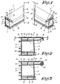
- Figure 1 schematically represents a method according to the invention for connecting two plastic jambs 1 and 2.
- Both jambs 1, 2 are built in an analogous manner and in this case have a central chamber 3 which is confined by four side walls 4, 5, 6 and 7.
- ribs 8 which are mutually connected at their free far end by an outer wall 9 of the jamb 1, 2.
- ribs 10 which are connected at their free far ends by an outer wall 11 of the jamb 1, 2.
- the latter outer wall 11 is lengthened and it is finished with a curvature 12 at its lengthened far end.
- This lengthened part of the outer wall 11 is hereby designed as a stop in a finished window or door frame.
- a finishing layer 13 such as for example a coating of lacquer.
- This coating of lacquer can have many different natures; it may be for example an epoxy polyurethane lacquer. It should be noted that the coating of lacquer 13 is represented somewhat thicker in figures 2, 4 and 5, for clarity's sake.
- both jambs are mitred at their far ends to be connected by means of cutting, whereby these far ends form the mutual contact surfaces 14, 15 respectively for connecting both jambs 1, 2.
- a part of the contact surface 14 is removed over a certain distance A so as to form an edge 16.
- a part of the contact surface 15 of the other jamb 2 is removed over a distance A in an analogous manner so as to form an edge 17.
- the above-mentioned distance A is preferably in the order of magnitude of 3 mm, but it can strongly vary as a function of the materials used, the aimed strength of the connection and the like.
- the width B of the part of the contact surfaces 14 and 15 which is removed represents a fraction of the thickness D of the outer wall 11 concerned.
- the remaining parts of the contact surfaces 14, 15 are heated to the melting temperature, after which the contact surfaces 14, 15 are pressed together.
- the heated contact surfaces 14, 15 melt together, whereby an appropriate pressure must be exerted to make both contact surfaces 14 and 15 melt together over a distance, which distance is preferably equal to or practically equal to the above-mentioned distance A.
- This removal of a part of the sealing 20 prevents the sealing 20, which is usually made of rubber, from curing while the jambs 1 and 2 are welded together, such that the sealing 20 can maintain its optimal elasticity.
- Figure 6 represents a variant whereby an insert angle 21 is applied which makes it possible to reinforce the connection between both jambs 1 and 2.
- this insert angle 21 consists of two legs 22, 23 which are made of plastic and which are mitred, either cut or sawn.
- the above-mentioned legs 22, 23 can also be formed by means of injection-moulding.
- the method for connecting the two jambs 1 and 2 with the use of the insert angle 21 consists in fixing, before both jambs 1 and 2 are connected, one of the above-mentioned legs 22, 23 in each of said jambs 1-2 by means of welding, gluing or the like, such that the mitred sides of these legs 22 and 23 are situated in one and the same plane or practically the same plane as the above-mentioned contact surfaces 14, 15 of the jambs 1 and 2.
- both jambs 1 and 2 are welded together, whereby the mitred sides of both legs 22 and 23 are welded together as well so as to form the above-mentioned insert angle 21.
- legs 22 and 23 must not necessarily be provided in a central chamber 3 of the jambs 1 and 2, but are preferably provided in chambers 19 which are situated at the removed part of the jambs 1 and 2.
- the edge 8 of the second jamb 2 coincides with the contact surface 15 of this jamb 2.
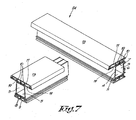
- figure 7 represents a variant whereby both jambs 1-2 are connected in the shape of a T-connection 24.
- the first jamb 1 is fixed with one of its far ends to a side wall 4 of the second jamb 2, to which end the contact surface 14 of the first jamb 1 is partly removed along at least one outer wall 11 of this jamb 1.
- the contact surface 15 of the second jamb 2 is in this case formed of a part of the above-mentioned side wall 4, out of which no part has to be removed, but which part, in case the side wall 4 is adjacent to one or two side walls 9, 11 which are provided with a coating of lacquer 13, only has to be partly heated, in particular over a surface which preferably corresponds to the remaining contact surface 14 of the first jamb 1.
- edges 16-17 of at least one of two jambs 1-2 to be connected can be partly heated briefly, whereby when both jambs 1-2 are welded together, the edges 16-17 of both jambs partly melt together.
- the present invention is by no means limited to the above-described method represented in the figures; on the contrary, such a method according to the invention for connecting two plastic jambs can be made according to different variants while still remaining within the scope of the invention.
Landscapes
- Engineering & Computer Science (AREA)
- Mechanical Engineering (AREA)
- Lining Or Joining Of Plastics Or The Like (AREA)
- Joining Of Corner Units Of Frames Or Wings (AREA)
- Wing Frames And Configurations (AREA)
Abstract
Description
- The present invention concerns a method for connecting two plastic jambs, in particular window jambs or the like.
- It is known to connect two plastic jambs by means of welding, in particular by heating their mutual contact surfaces and subsequently pressing them together, such that the parts which have been softened by the heating can be pressed into one another and can be melted together.
- A disadvantage of this method is that when one or several of the side walls of the jambs have been finished with a coating of lacquer or the like, this coating of lacquer will be scorched while the contact surfaces are being heated, as a result of which, when both jambs are connected, the coating of lacquer around the weld will be scorched, whereby the original, usually white colour of the jambs becomes visible.
- With the known method this weld, after both jambs have been connected, will be cut away up to a certain depth, whereby a strip of the synthetic material out of which the jambs have been made becomes visible, which strip is then touched up by hand in a colour which corresponds to that of the lacquer.
- A disadvantage of the present method is that a small groove is created at the weld as the scorched lacquer is cut away, which is unaesthetic. In short, the present method does not allow for a perfect finish of the connection of the two plastic jambs.
- Another disadvantage of the known method is that cutting away and manually touching up the weld is relatively time-consuming and expensive.
- Moreover, the quality of touching up the colour manually is not good in many cases, and the colourfastness of the touched-up weld cannot be guaranteed.
- Also, the present invention aims to remedy one or several of the preceding and other disadvantages.
- To this end, the invention concerns a method for connecting two plastic jambs for a window or the like which mainly consists in heating a contact surface of at least one of both jambs and pressing it against a corresponding contact surface of the other jamb so as to weld them together whereby, before both jambs are welded, a part of the contact surface of at least one of both jambs is removed along at least one of the outer walls of this jamb over a certain distance so as to form an edge which corresponds to a joint to be realised, and whereby at least one of the jambs, before both jambs are connected, is provided with a coating of lacquer on its above-mentioned outer wall.
- An advantage of the present invention is that the above-mentioned coating of lacquer must not be heated anywhere, such that scorching of the lacquer can be avoided.
- Preferably, the width of the removed part is only a fraction of the thickness of the above-mentioned outer wall.
- An advantage of the preferred method is that the stability of the formed angle joint is sufficiently large to be applied in window or door frames.
- Another advantage is that an angle joint which can be obtained according to the preferred method can be made watertight and windproof without any additional measures being required, such as for example applying a silicone.
- In order to better explain the characteristics of the present invention, the following method according to the invention is described as an example only without being limitative in any way, with reference to the accompanying drawings, in which:
- figure 1 schematically represents a method according to the invention;
- figure 2 represents a view according to arrow F2 in figure 1 to a larger scale;
- figure 3 represents two jambs which are connected according to a method of the invention;
- figure 4 represents a section according to line IV-IV in figure 3;
- figure 5 represents a variant of figure 2;
- figures 6 and 7 represent variants of figure 1.
- Figure 1 schematically represents a method according to the invention for connecting two
plastic jambs - Both
jambs central chamber 3 which is confined by fourside walls - On one of these
side walls 5 are providedribs 8 which are mutually connected at their free far end by anouter wall 9 of thejamb - In an analogous manner, on an
opposite side wall 7 of thecentral chamber 3, are providedribs 10 which are connected at their free far ends by anouter wall 11 of thejamb - In this case, the latter
outer wall 11 is lengthened and it is finished with acurvature 12 at its lengthened far end. This lengthened part of theouter wall 11 is hereby designed as a stop in a finished window or door frame. - On the above-mentioned
outer wall 11 of thejambs finishing layer 13, such as for example a coating of lacquer. This coating of lacquer can have many different natures; it may be for example an epoxy polyurethane lacquer. It should be noted that the coating oflacquer 13 is represented somewhat thicker in figures 2, 4 and 5, for clarity's sake. - In this case, both jambs are mitred at their far ends to be connected by means of cutting, whereby these far ends form the
mutual contact surfaces jambs - According to the invention, along the
outer wall 11 of thejamb 1, a part of thecontact surface 14 is removed over a certain distance A so as to form anedge 16. - Preferably, a part of the
contact surface 15 of theother jamb 2 is removed over a distance A in an analogous manner so as to form anedge 17. - The above-mentioned distance A is preferably in the order of magnitude of 3 mm, but it can strongly vary as a function of the materials used, the aimed strength of the connection and the like.
- According to the invention and as represented in figure 2, the width B of the part of the
contact surfaces outer wall 11 concerned. - It should be noted that on the spot where the above-mentioned
ribs 10 connect to the correspondingouter wall 11, the width of the removed part is somewhat larger than the thickness D of theouter wall 11 concerned. - According to the method of the invention, the remaining parts of the
contact surfaces contact surfaces - As they are pressed together, the heated
contact surfaces contact surfaces - As is represented in figure 3, the
edges jambs joint 18. - When the
contact surfaces outer walls 11 will be pushed away tochambers 19 which are defined between theside wall 7 of thecentral chamber 3, theouter wall 11 and theribs 10. - The same will happen at the location of the
ribs 10, such that when bothjambs outer walls 11 will be locally connected over their entire length, which is clearly represented in figure 4. - This melting together of the
outer walls 11 of bothjambs jambs - In order to be able to form an aesthetic right angle, as is represented in figure 1, at the above-mentioned
curvature 12, a part of theouter wall 11 which is adjacent to thecontact surface 14 is removed over a distance A' which is somewhat smaller than the above-mentioned distance A. In other words, at thecurvature 12, a little less material is removed than elsewhere along thisouter wall 11, since otherwise, when two plastic jambs melt into an angle joint, the jambs could slightly diverge. - In the case, as is represented in figure 5, where a
sealing 20 is provided in the part of theouter wall 11 forming a stop, a part of this sealing 20 is preferably removed. - This removal of a part of the sealing 20 prevents the sealing 20, which is usually made of rubber, from curing while the
jambs - Figure 6 represents a variant whereby an insert angle 21 is applied which makes it possible to reinforce the connection between both
jambs - In this case, this insert angle 21 consists of two
legs legs - The method for connecting the two
jambs jambs legs legs contact surfaces jambs - Finally, both
jambs legs - It should be noted that the above-mentioned
legs central chamber 3 of thejambs chambers 19 which are situated at the removed part of thejambs - As an alternative for an insert angle 21, it is also possible, after two jambs have been connected, to inject a glue or curing foam in one or several of the
chambers 19, to which end, in the finished window, in a hidden place of thejambs chambers 19. - It is clear that along more than one side wall of each
jamb contact surface jambs - It should be noted that, moreover, it is not necessary to remove a part of both contact surfaces, for it is also possible to remove a part of the
contact surface 14 of thefirst jamb 1 and to subsequently heat it, whereas thecontact surface 15 of thesecond jamb 2 is only locally heated, in particular over a surface which corresponds to the remaining part of thecontact surface 14, after which thefirst jamb 1 can be pressed with itscontact surface 14 against thecontact surface 15 of thesecond jamb 2. - In the latter case, the
edge 8 of thesecond jamb 2 coincides with thecontact surface 15 of thisjamb 2. - Finally, figure 7 represents a variant whereby both jambs 1-2 are connected in the shape of a T-
connection 24. - In this case, the
first jamb 1 is fixed with one of its far ends to aside wall 4 of thesecond jamb 2, to which end thecontact surface 14 of thefirst jamb 1 is partly removed along at least oneouter wall 11 of thisjamb 1. - The
contact surface 15 of thesecond jamb 2 is in this case formed of a part of the above-mentionedside wall 4, out of which no part has to be removed, but which part, in case theside wall 4 is adjacent to one or twoside walls lacquer 13, only has to be partly heated, in particular over a surface which preferably corresponds to theremaining contact surface 14 of thefirst jamb 1. - Finally, it should be noted that the above-mentioned edges 16-17 of at least one of two jambs 1-2 to be connected can be partly heated briefly, whereby when both jambs 1-2 are welded together, the edges 16-17 of both jambs partly melt together.
- The present invention is by no means limited to the above-described method represented in the figures; on the contrary, such a method according to the invention for connecting two plastic jambs can be made according to different variants while still remaining within the scope of the invention.
Claims (11)
- Method connecting two plastic jambs (1-2) for a window or the like which mainly consists in heating a contact surface (14) of at least one of both jambs (1) and pressing it against a corresponding contact surface (15) of the other jamb (2) so as to weld them together whereby, before both jambs (1-2) are welded, a part of the contact surface (14) of at least one of both jambs (1-2) is removed along at least one of the outer walls (9,11) of this jamb (1, 2) over a certain distance (A) so as to form an edge (16, 17) which corresponds to a joint (18) to be realised, characterised in that at least one of the jambs (1, 2), before both jambs (1, 2) are connected, is provided with a coating of lacquer (13) on its above-mentioned outer wall (9, 11).
- Method according to claim 1, characterised in that the width (B) of the removed part represents only a fraction of the thickness (D) of the above-mentioned outer wall (9, 11).
- Method according to claim 1, characterised in that both jambs (1-2) are pressed together with their contact surfaces (14-15) until the above-mentioned edges (16-17) of both jambs (1-2) touch or almost touch and thus form the joint (18) to be realised.
- Method according to claim 1, characterised in that at least a fraction of the edges (16-17) of at least one of both jambs is heated and, during the welding of the jambs (1-2), is welded to a corresponding edge (16-17) of the other jamb (1-2).
- Method according to claim 2, whereby the outer wall (9, 11) of the jambs (1, 2) to be connected is provided on different cross ribs (8, 10), characterised in that the part of the contact surfaces (14, 15) to be removed has a width (B') at the above-mentioned ribs (3, 10) which is larger than the thickness (D) of the outer wall (9, 11).
- Method according to claim 1, whereby one of the outer walls (11) of the jambs (1, 2) to be connected is lengthened and is provided with a curvature (12), characterised in that the distance A' over which a part of the contact surface (14, 15) has been removed at the curvature (12), is smaller than the above-mentioned distance A.
- Method according to claim 1, characterised in that the specific distance A over which a part of the contact surfaces (14-15) of the jambs (1-2) is removed, amounts to some 3 mm.
- Method according to claim 1, characterised in that the contact surface (14, 15) of which no part is removed, is partly heated so as to connect both jambs (1-2).
- Method according to claim 1, characterised in that the jambs (1-2) are cylindrical and in that an insert angle (12) is provided in their far ends to be connected which consists of two legs (13-14) of which each time at least one side is mitred, which are each fixed in a jamb (1-2), such that their mitred sides are situated in the same or practically the same plane as the contact surface (3-4) of the jambs (1-2), after which both jambs (1-2) and the above-mentioned sides of the legs (13-14) are welded together.
- Method according to claim 1, characterised in that in the cylinders of two welded jambs (1-2) is injected a glue or a foam.
- Method according to claim 1, characterised in that the above-mentioned jambs are provided with a part forming a stop in which a sealing (20) is provided, whereby before both jambs (1-2) are welded, at least a part of the sealing (20) is removed at the contact surface (14-15) between both jambs (1-2).
Applications Claiming Priority (1)
| Application Number | Priority Date | Filing Date | Title |
|---|---|---|---|
| BE200500012A BE1016401A3 (en) | 2005-01-11 | 2005-01-11 | METHOD FOR CONNECTING TWO PLASTIC PROFILES |
Publications (2)
| Publication Number | Publication Date |
|---|---|
| EP1679180A2 true EP1679180A2 (en) | 2006-07-12 |
| EP1679180A3 EP1679180A3 (en) | 2007-03-28 |
Family
ID=34974771
Family Applications (1)
| Application Number | Title | Priority Date | Filing Date |
|---|---|---|---|
| EP20050078042 Withdrawn EP1679180A3 (en) | 2005-01-11 | 2005-12-29 | Method for connecting two plastic jambs |
Country Status (2)
| Country | Link |
|---|---|
| EP (1) | EP1679180A3 (en) |
| BE (1) | BE1016401A3 (en) |
Cited By (4)
| Publication number | Priority date | Publication date | Assignee | Title |
|---|---|---|---|---|
| ITMO20120057A1 (en) * | 2012-03-07 | 2013-09-08 | Graf Synergy Srl | "METHOD AND DEVICE FOR WELDING PROFILES IN PLASTIC MATERIAL, IN PARTICULAR PVC" |
| ITMO20120200A1 (en) * | 2012-08-20 | 2014-02-21 | Graf Synergy Srl | METHOD FOR WELDING PROFILES IN PLASTIC MATERIAL, IN PARTICULAR PVC |
| EP3275633A1 (en) * | 2016-07-29 | 2018-01-31 | Urban GmbH & Co. Maschinenbau KG | Method for welding profile rods |
| PL422594A1 (en) * | 2017-08-21 | 2019-02-25 | Fimtec-Polska Spółka Z Ograniczoną Odpowiedzialnością Spółka Komandytowa | Method for manufacturing windows from plastic material |
Family Cites Families (8)
| Publication number | Priority date | Publication date | Assignee | Title |
|---|---|---|---|---|
| DE2923453A1 (en) * | 1979-06-09 | 1980-12-11 | Besler Armin | Welding multichamber thermoplastic profiles - for window and door frames, rebating outside walls to eliminate visible welds |
| DE2923935A1 (en) * | 1979-06-13 | 1980-12-18 | Besler Armin | Plastics profile butt welding - involves applying recessed groove along joints to absorb upsetting flash |
| DE3039733A1 (en) * | 1980-10-21 | 1982-05-19 | Gebrüder Kömmerling Kunststoffwerke GmbH, 6780 Pirmasens | Butt welding mitred thermoplastic frames - in which pressed out weld polymer fills lateral slots to keep outer surfaces clean |
| JP2540218B2 (en) * | 1989-12-05 | 1996-10-02 | フクビ化学工業株式会社 | Synthetic resin window frame and manufacturing method thereof |
| US5603585A (en) * | 1994-05-17 | 1997-02-18 | Andersen Corporation | Joint structure and method of manufacture |
| GB9724909D0 (en) * | 1997-11-25 | 1998-01-28 | Rehau Ltd | Welding method |
| AT410066B (en) * | 2000-05-09 | 2003-01-27 | Lisec Peter | PROCESS FOR JOINING HOLLOW PROFILE STRIPS BY WELDING |
| GB2376656A (en) * | 2001-06-21 | 2002-12-24 | Gti Kombimatec Machines Ltd | Removing notches from the weld face areas of components, to locally reduce waste sprue produced during thermal bonding, apparatus, method & preparation |
-
2005
- 2005-01-11 BE BE200500012A patent/BE1016401A3/en not_active IP Right Cessation
- 2005-12-29 EP EP20050078042 patent/EP1679180A3/en not_active Withdrawn
Cited By (5)
| Publication number | Priority date | Publication date | Assignee | Title |
|---|---|---|---|---|
| ITMO20120057A1 (en) * | 2012-03-07 | 2013-09-08 | Graf Synergy Srl | "METHOD AND DEVICE FOR WELDING PROFILES IN PLASTIC MATERIAL, IN PARTICULAR PVC" |
| ITMO20120200A1 (en) * | 2012-08-20 | 2014-02-21 | Graf Synergy Srl | METHOD FOR WELDING PROFILES IN PLASTIC MATERIAL, IN PARTICULAR PVC |
| EP3275633A1 (en) * | 2016-07-29 | 2018-01-31 | Urban GmbH & Co. Maschinenbau KG | Method for welding profile rods |
| EP4520510A1 (en) * | 2016-07-29 | 2025-03-12 | Urban GmbH & Co. Maschinenbau KG | Method for welding profile rods |
| PL422594A1 (en) * | 2017-08-21 | 2019-02-25 | Fimtec-Polska Spółka Z Ograniczoną Odpowiedzialnością Spółka Komandytowa | Method for manufacturing windows from plastic material |
Also Published As
| Publication number | Publication date |
|---|---|
| EP1679180A3 (en) | 2007-03-28 |
| BE1016401A3 (en) | 2006-10-03 |
Similar Documents
| Publication | Publication Date | Title |
|---|---|---|
| US4492063A (en) | Extruded plastics material hollow profiled strip for window frames, window frames produced from this type of profiled strips and method for the production of a window frame of this type | |
| CA2202046C (en) | Joint structure and method of manufacture | |
| US4481701A (en) | Cored plastics profiles and manufacture of frames for windows and the like therefrom | |
| US5887398A (en) | Synthetic door casement structure for patio doors and like, and method | |
| US5157885A (en) | Door leaf or casing frame and process for its manufacture | |
| KR100437917B1 (en) | Method for Producing Bent Hollow Profile Strips | |
| US20080060314A1 (en) | Corner joint for pultruded window frame | |
| US20060272275A1 (en) | Method for the production of a furniture body | |
| EP2085558B1 (en) | Method for manufacturing a plastic casing, window or door | |
| EP0105411A2 (en) | Method of forming a laminated product and product produced by the method | |
| US20010039995A1 (en) | Process for joining hollow section strips by welding | |
| US6467219B1 (en) | Shutter rail to stile joint | |
| JPH11325010A5 (en) | ||
| GB2026125A (en) | Joint forming | |
| EP0907000A1 (en) | A door slab assemble structure for the partly hollow door skin and glass | |
| WO2011116436A2 (en) | Method for the connection of two jambs, and a jamb which is suitable for application in such a method | |
| KR101896749B1 (en) | manufacturing method of composite materials window | |
| EP0235442A1 (en) | A building frame assembly and a method of manufacturing such an assembly | |
| JP2000141403A (en) | Method of joining resin molded products | |
| KR102712956B1 (en) | A method for manufaturing door panel of funiture with improved durability | |
| CN111219123A (en) | Method for manufacturing composite material window | |
| AU532869B2 (en) | Cored plastics profiles and manufacture of frames for windowsand tje like therefrom | |
| GB2101658A (en) | Laminated door | |
| US20140311688A1 (en) | Clad slat | |
| JPH08100570A (en) | Decorative edge material and method of manufacturing decorative edge material |
Legal Events
| Date | Code | Title | Description |
|---|---|---|---|
| PUAI | Public reference made under article 153(3) epc to a published international application that has entered the european phase |
Free format text: ORIGINAL CODE: 0009012 |
|
| AK | Designated contracting states |
Kind code of ref document: A2 Designated state(s): AT BE BG CH CY CZ DE DK EE ES FI FR GB GR HU IE IS IT LI LT LU LV MC NL PL PT RO SE SI SK TR |
|
| AX | Request for extension of the european patent |
Extension state: AL BA HR MK YU |
|
| PUAL | Search report despatched |
Free format text: ORIGINAL CODE: 0009013 |
|
| AK | Designated contracting states |
Kind code of ref document: A3 Designated state(s): AT BE BG CH CY CZ DE DK EE ES FI FR GB GR HU IE IS IT LI LT LU LV MC NL PL PT RO SE SI SK TR |
|
| AX | Request for extension of the european patent |
Extension state: AL BA HR MK YU |
|
| 17P | Request for examination filed |
Effective date: 20070731 |
|
| AKX | Designation fees paid |
Designated state(s): AT BE BG CH CY CZ DE DK EE ES FI FR GB GR HU IE IS IT LI LT LU LV MC NL PL PT RO SE SI SK TR |
|
| 17Q | First examination report despatched |
Effective date: 20081014 |
|
| STAA | Information on the status of an ep patent application or granted ep patent |
Free format text: STATUS: THE APPLICATION IS DEEMED TO BE WITHDRAWN |
|
| 18D | Application deemed to be withdrawn |
Effective date: 20090225 |