EP1677401A1 - emergency boom for overhead lines - Google Patents
emergency boom for overhead lines Download PDFInfo
- Publication number
- EP1677401A1 EP1677401A1 EP04030889A EP04030889A EP1677401A1 EP 1677401 A1 EP1677401 A1 EP 1677401A1 EP 04030889 A EP04030889 A EP 04030889A EP 04030889 A EP04030889 A EP 04030889A EP 1677401 A1 EP1677401 A1 EP 1677401A1
- Authority
- EP
- European Patent Office
- Prior art keywords
- mast
- ground
- carrier unit
- anchor
- emergency linkage
- Prior art date
- Legal status (The legal status is an assumption and is not a legal conclusion. Google has not performed a legal analysis and makes no representation as to the accuracy of the status listed.)
- Withdrawn
Links
Images


Classifications
-
- H—ELECTRICITY
- H02—GENERATION; CONVERSION OR DISTRIBUTION OF ELECTRIC POWER
- H02G—INSTALLATION OF ELECTRIC CABLES OR LINES, OR OF COMBINED OPTICAL AND ELECTRIC CABLES OR LINES
- H02G1/00—Methods or apparatus specially adapted for installing, maintaining, repairing or dismantling electric cables or lines
- H02G1/02—Methods or apparatus specially adapted for installing, maintaining, repairing or dismantling electric cables or lines for overhead lines or cables
- H02G1/04—Methods or apparatus specially adapted for installing, maintaining, repairing or dismantling electric cables or lines for overhead lines or cables for mounting or stretching
Definitions
- the invention relates to an emergency linkage according to the preamble of claim 1, and a method for the construction of an emergency linkage, in particular in the event of failure of overhead transmission towers, according to the preamble of claim 12.
- the transmission and distribution of electrical energy takes place - especially in the range of high voltages - over overhead lines.
- overhead transmission masts are used, on which the generally bare cables are suspended.
- the masts are usually designed as constructions with multiple trusses or jibs to which the conductors are attached via insulators.
- the masts for high-voltage transmission are generally arranged at intervals of about 400m, but the arrangement must of course be adapted to the conditions of the terrain.
- the height of the masts is usually in the order of a few 10m, a minimum height of the overhead lines above the ground is due to the risk of electric shocks for safety reasons prescribed.
- the object of the present invention is therefore to provide an emergency linkage, which, in particular in the event of failure of overhead transmission towers, can be erected in a generically short time.
- Another object of the invention is to provide a method by means of which an erection of an emergency linkage for overhead lines is made possible with generic time-consuming.
- a method for erecting an emergency linkage in particular in the event of failure of high-voltage masts or overhead lines, it is provided that the location of the damaged pole or its immediate vicinity is generally within a short time-in particular only a few hours - set up an emergency linkage. For this purpose, all required building materials are transported to the given location and are available there.
- a carrier unit, and several anchor units are placed on the ground. Subsequently, the carrier unit is connected via carrier anchoring means, iA anchor cables, with two or more anchor units, so that a stabilization of the carrier unit is achieved.
- Mast anchoring means are attached to a provided replacement mast, which can be designed as a support, guy or end mast and is equipped with insulators, eg long-rod or chain insulators.
- the mast anchoring means may already be attached to the mast.
- the mast is - generally by helicopter, mobile crane or tree - erected so that it is approximately upright on level ground (in uneven terrain, eg on a hillside, the mast is generally inclined), and the mast anchor ropes attached to the mast connected to the anchor units. It is provided in particular to arrange the mast ball-jointed on the carrier unit in order to allow a certain freedom of movement of the mast in two spatial directions (directions perpendicular to the mast).
- the carrier unit may be any part suitable for the attachment of a mast according to the invention.
- the carrier unit is designed so that a trough-like or trough-shaped device is provided with a lifting or bulge, in which the mast boom is articulated ball.
- the shape of the device is thus such that it is suitable for placement of the mast boom via a ball joint and possibly adapted to the shape of the joint, thus supporting the ball-jointed movement of the mast.
- the carrier unit may be one or more pieces.
- the carrier unit is composed of a lower plate with an attachment.
- the lower plate is preferably an excavator mattress and the attachment, for example, a type of steel tub or steel plate with side supports or with integrated cylindrical elevation.
- the mast is then placed in the steel tub or in a trough between the side supports or in the cylinder and set up.
- the carrier unit obtains the necessary stability by being connected to anchor units by means of carrier anchoring means.
- fastening means are provided in, on or on the carrier unit, which allow attachment of the carrier anchoring means.
- attachment means may be, for example, eyelets, preferably on the steel plate or the trough-shaped device are provided.
- the carrier anchoring means are thus fastened on the one hand via eyelets on the carrier unit.
- the support anchoring means are connected to anchor units directly or indirectly.
- the anchor units are components for anchoring the mast boom and / or the carrier unit (s). Number and distance of the anchor units to the carrier unit or to the mast are calculated so that a stabilization of the carrier unit or the mast is ensured by the anchor units.
- the anchor units are thus positioned in - due to terrain conditions and requirements, eg with regard to stability, to the emergency linkage - given / m number, location and distance to the carrier unit or to the mast and serve the stable support of mast and carrier unit.
- the number of anchor units used varies with the circumstances, but in general at least four anchoring blocks are needed.
- anchor units can be one-piece or multi-piece, eg blocks or pedestals made of concrete.
- a frame of angle iron is provided on which one or more blocks, in particular of concrete, are provided, such a concrete block weighs for example 2.5 tons.
- the anchor units formed, for example, as steel tubes are buried in the ground.
- the anchor units which protrude in particular from the ground, and a connection to the mast and support anchoring means for fastening the mast and support anchoring means allow.
- the mast and / or carrier anchor ropes can thus be fixed by means of facilities on or above the ground to the buried steel pipes in the ground.
- the anchor units can have any shape that suits the purpose and can be designed as desired. Concrete as a material has the required properties in terms of weight, machinability, cost, etc. and is therefore preferred, but could just as gray cast iron can be used.
- One or more means for attaching the mast and support anchoring means may be provided on the anchor units.
- mast and carrier anchoring means usually commercially available anchor ropes - which are generally steel ropes - used.
- anchor ropes are generally provided with attachment means, e.g. Shackle, provided.
- the mast to be built can have the characteristics of a supporting, guy or end mast. It can be designed as any type of mast for the transmission of electrical energy by means of overhead lines, in particular the emergency linkage mast for 380kV, 220kV and 110kV is provided.
- the "replacement pylons" are generally placed at intervals of about 400m, so that the conductors are not below the minimum distance to the ground, even with a calculated maximum sag.
- the mast is composed of individual mast segments, one of which is for example 5m long, and has at its bottom end facing a ball-jointed device. About the ball joint of the mast on the carrier unit - or on the carrier unit provided device for the storage of the joint - stored.
- the individual segments may be formed the same or different lengths. You can have a, for example, trapezoidal geometry, which ensures a confusion - especially from the point of view of time pressure - construction.
- the overhead power pole can be transported in parts to the installation site and assembled there, it can of course just as a whole be delivered and set up.
- the mast is made of aluminum, so has a generic low weight.
- insulators such as long-rod or chain insulators, medium or directly connected. They serve in a known manner the inclusion of conductors.
- the conductor cables of the power network are attached to the insulators, generally suspended or guyed.
- the conductors used are generally non-insulated conductors.
- an auxiliary rope is optionally provided on the mast, which can be moved, for example, by means of circulation rollers from the lower to the upper region of the mast and vice versa.
- the circulating rollers can be installed as an inlet roller at the lower end of the mast and as an outlet roller at the upper end of the mast.
- the rope is pulled before erection of the mast through the mast and outside on Mast pulled down again. It can also be provided a second, third or further auxiliary or transport rope.
- further circulating rollers are preferably present in the mast parts with the chain or long-rod insulators, which offer further transport options.
- the various circulating rollers are in particular also rotatable about an axis parallel to the mast (longitudinal axis), ie they can be rotated about the mast, so that it is possible to work on each side of the mast.
- the mast top may have a turntable with eg some eyelets. It would be possible to anchor the mast only by means of mast anchor ropes attached to the turntable, which would allow a great freedom of movement on the mast boom itself - eg regarding auxiliary ropes and cable transport.
- a mast 1 which may belong to a supporting, guy or final mast, such as a lattice mast made of aluminum, is here provided with three insulators 2.
- insulators 2 it is possible to use suspended or standing insulators made of, for example, plastic, in particular long-rod insulators.
- chain insulators of eg high-strength plastic are generally used.
- Attached to the mast top is a ground wire 3 'to protect the line from lightning strikes.
- At the insulators 2 conductors 3 for the transmission of electrical energy, such as electricity, suspended.
- the ropes - bundle conductors in particular bundles of two, - are composite ropes of steel and aluminum with a diameter of approx. 22.4 mm. If the mast 1 is set up as emergency linkage for a damaged overhead line, then, if that is possible, the ladder cables of the defective pole are used as ladder cables 3 of the emergency linkage. If the "old" ladder ropes can not be used, new phase conductors are attached to the emergency linkage mast 1 and a bridge to the existing line is built. On mast 1 are means for securing mast anchoring means, which are here mast anchor ropes 4 - in particular steel - provided.
- mast anchor ropes 4 can be attached to the mast 1, for example, approximately at the height of the insulators 2 and the mast top.
- a turntable 10 FIG. 2 at the mast top fastening means for mast anchor ropes 4, such as eyelets, and the anchoring of the mast 1 with the anchor units 6 on the turntable 10 takes place.
- the anchor units 6 for anchoring the mast 1 are usually formed with a frame made of angle iron, on which frame blocks of eg concrete or gray cast iron are made. They are set up in a calculated number and distances to the mast 1.
- the anchor pegs are calculated to take the load of the anchors. They can still be designed with gripping devices or supports, for example so-called “mountain supports” or “earth hooks", in order to gain additional hold in the ground.
- the mast 1 is constructed of generic light material, in particular aluminum, so that the generic light and high mast 1 very quickly, ie for example in a few hours, can be placed.
- the mast 1 is erected on a carrier unit 5 designed for this purpose, which takes up the weight of the mast 1 and prevents sinking into the ground.
- the carrier unit 5 is shown here as a lower plate 5 'with trough-shaped attachment 5''arranged thereon-a type of steel tub.
- the mast 1 has at its lower end a ball-jointed device which is mounted in the steel tub. After lowering the ball joint 7 in the tub, the ball joint 7 is provided with a cover 8 and held in the tub, for example by the lid 8 is screwed.
- The, for example, tub-shaped support means 5 can still be padded with a flange. This mounting of the mast 1 is provided to the of the conductors 3 outgoing forces, eg tensile forces to shift from the mast 1 to the anchor units 6.
- Fig. 2 shows the mast tree as such with additional facilities for working or auxiliary ropes.
- the mast 1 is designed here as a lattice mast made of aluminum and composed of individual mast segments 1a.
- the Mast segments 1a are connected to each other, in particular set and screwed together.
- the mast 1 has at its lower and upper end as an inlet and outlet roller formed circulating rollers 9 ', 9 "for an auxiliary rope on 1 pulled and brought back over the trained as an outlet roller roller 9 "outside on the mast. It serves as a working rope for the transport of components along the height of the mast 1.
- the mast 1 is here with other facilities - circulation rollers 9 '''- provided for more auxiliary ropes.
- the various circulation rollers 9 ', 9'',9''' are designed so that they are rotatable about an approximately vertical to the ground and approximately parallel to the mast 1 axis, so that components can be transported on the entire circumference of the mast 1.
- Fig. 3 Shown in Fig. 3 is a detailed section of the upper part of the mast 1.
- the turntable 10 at the mast top provides fasteners for mast anchor ropes 4.
- the earth wire 3 ' is generally attached to the mast top.
- the circulation roller 9 '' referred to the mast top as a discharge role, an auxiliary rope for the transport of subsequently to be installed on the mast 1 components on the mast 1 can be pulled up.
- Fig. 4 shows in detail a section of the lower mast part with a trained as an inlet roller roller 9 'for a utility and working rope. Shown is also the support unit 5, which is composed here of a plate 5 'arranged thereon steel tub.
- the lower plate 5 ' is a so-called excavator mattress, which generally refers to constructions made of hardwood, which are suitable for a variety of tasks, such as driveable construction route, as ship's floor, as a road surface on steel girder a makeshift bridge, as a border of a bulk storage, as protection Extremely loaded hard rubber tires of lifting vehicles, for repairs between railway tracks and wherever large loads on difficult ground have to be moved quickly and cost-effectively.
- the upper support unit is a trough-shaped attachment 5 '' for supporting the ball at the mast end, which trough-shaped attachment 5 "side supports 5 '''which allow a stable mounting of the ball joint 7 of the mast 1.
- the side supports 5''' are in particular so is formed and arranged so that a kind of trough is formed, in which the ball joint 7 can be sunk in.
- the ball joint cover 8 It is understood that the ball-jointed mounting of the mast 1 on all types of masts, such as wood -, steel pipe or steel framework masts, can be applied.
- the support steel unit has mounting options for carrier anchor ropes 4 'for anchoring the carrier-steel unit to the anchor units 6.
- the carrier unit 5 is set up and connected to two or more anchor units 6 with carrier anchoring means, which are usually anchor steel cables.
- carrier anchoring means which are usually anchor steel cables.
- FIG. 5 shows a top view of the trough-shaped attachment 5 "of the carrier unit 5.
- a device generally made of steel, provided here with carrying handles 11, is provided on the excavator mattress, not shown here, for the ball-jointed receiving of the overhead line mast It may also be mounted on the lower plate 5 ', or it may be integrated in the lower plate 5', ie the carrier unit 5 could be an integral part the side supports 5 "'- shown is a kind of circular or trough-shaped storage unit for receiving the ball joint 7 of the mast. 1
- To carry the mast 1 requires a device that can accommodate and distribute the mast weight and provides a way to ball-joint storage of the mast 1.
- Such a device is in this embodiment by a not shown excavator mattress with a trough-shaped attachment 5 '' made of steel with side supports 5 ''', in the center of which not shown ball joint 7 of the mast 1 recessed in a circular trough and a cover. 8 is kept in the trough provided.
Abstract
Description
Die Erfindung bezieht sich auf ein Notgestänge gemäss dem Oberbegriff des Anspruchs 1, sowie ein Verfahren zur Errichtung eines Notgestänges, insbesondere beim Ausfall von Freileitungsmasten, gemäss dem Oberbegriff des Anspruchs 12.The invention relates to an emergency linkage according to the preamble of
Die Übertragung und Verteilung elektrischer Energie erfolgt - besonders im Bereich hoher Spannungen - über Freileitungen. Dazu werden Freileitungsmaste eingesetzt, an denen die im Allgemeinen blanken Leitungsseile aufgehängt werden. Die Maste sind meist als Konstruktionen mit mehreren Traversen bzw. Auslegern ausgeführt, an denen die Leiterseile über Isolatoren befestigt sind. Die Maste für Hochspannungs-Übertragungen sind im Allgemeinen in Abständen von ca. 400m angeordnet, die Anordnung muss aber selbstverständlich an die Gegebenheiten des Geländes angepasst werden. Die Höhe der Maste ist meist in der Grössenordnung einiger 10m, eine Mindesthöhe der Freileitungen über dem Boden ist aufgrund der Gefahr elektrischer Schläge aus Sicherheitsgründen vorgeschrieben. Auch ein Kontakt der Leitungen untereinander muss nach Möglichkeit verhindert werden, d.h. die neben- oder untereinander angeordneten Leiterseile bzw. Traversen müssen einen Abstand zueinander einnehmen, der einen Kontakt der Leitungen auch bei Ausschlag der Leitungsseile ausschliesst. Nichtsdestoweniger kommt es immer wieder zu Ausfällen von Freileitungen, beispielsweise bei extremen Wetterbedingungen wie Stürmen hoher Windenergie oder in Fällen mutwilliger Beschädigung. Der Ausfall eines Freileitungsmastes kann ein Versagen ganzer Hochspannungsleitungen oder Hochspannungsleitungsabschnitte der elektrischen Stromversorgung zur Folge haben, was mitunter einen lang andauernden Stromausfall für ganze Regionen und hohe Verluste für Industrie und Wirtschaft bedeutet. Um beim Ausfall von Stromleitungen eine möglichst rasche Wiederversorgung mit elektrischer Energie zu erreichen, müssen beschädigte Maste in möglichst kurzer Zeit ersetzt bzw. Übergangsmaste für Freileitungen rasch eingesetzt werden.The transmission and distribution of electrical energy takes place - especially in the range of high voltages - over overhead lines. For this purpose, overhead transmission masts are used, on which the generally bare cables are suspended. The masts are usually designed as constructions with multiple trusses or jibs to which the conductors are attached via insulators. The masts for high-voltage transmission are generally arranged at intervals of about 400m, but the arrangement must of course be adapted to the conditions of the terrain. The height of the masts is usually in the order of a few 10m, a minimum height of the overhead lines above the ground is due to the risk of electric shocks for safety reasons prescribed. Even a contact of the lines with each other must be prevented if possible, ie the juxtaposed or mutually arranged conductor cables or trusses must take a distance from each other, which excludes a contact of the lines even when rash of the cables. Nonetheless, there are frequent failures of overhead lines, for example in extreme weather conditions such as high wind energy storms or in cases of deliberate damage. The failure of an overhead power pole can result in failure of entire high voltage power lines or high voltage power line sections of the electrical power supply, sometimes resulting in long-lasting power outages for entire regions and high losses to industry and economics. In case of failure of Power lines to achieve the fastest possible re-supply of electrical energy, damaged masts must be replaced in the shortest possible time or transition masts for overhead lines are used quickly.
Im Stand der Technik eingesetzte Lösungen sind mit hohem Aufwand und Kosten verbunden, insbesondere in schwierigem Gelände. Im Allgemeinen werden Portalmasten aufgestellt, welche aber in der Höhe beschränkt, und deshalb - aufgrund des vorgeschriebenen Mindestabstandes der Seile zum Boden hin und untereinander - nur eingeschränkt einsetzbar sind. Des Weiteren besteht ein hoher Platzbedarf an ebenem Gelände, der eventuell mit Bagger oder Räumfahrzeugen hergestellt werden muss.
Es besteht ein Bedarf an einem Verfahren, welches eine gattungsgemäss schnelle und kostengünstige Möglichkeit zur Errichtung von Übergangs-Ersatzmasten zur Verteilung und Übertragung hoher Energien angibt und an einer Vorrichtung - im Folgenden als Notgestänge bezeichnet -, welche in gattungsgemäss kurzer Zeit errichtet werden kann, zum Aufhängen von Hochspannungs-Freileitungen geeignet ist und alle Anforderungen an Stabilität bzgl. auftretenden Zug-, Druck-, Torsionsbeanspruchungen, etc. erfüllt.Solutions used in the prior art are associated with high costs and costs, especially in difficult terrain. In general, portal masts are installed, but limited in height, and therefore - due to the minimum distance of the ropes to the ground and between them - are only limited use. Furthermore, there is a high space requirement on flat terrain, which may need to be made with excavators or clearing vehicles.
There is a need for a method which provides a generic fast and cost-effective way to build transitional replacement pylons for distribution and transmission of high energy and a device - hereinafter referred to as emergency linkage - which can be built in the generic short time, for Suspension of high-voltage overhead lines is suitable and meets all requirements for stability with respect to occurring tensile, compressive, Torsionsbeanspruchungen, etc.
Die Aufgabe der vorliegenden Erfindung besteht daher darin, ein Notgestänge bereitzustellen, welches, insbesondere beim Ausfall von Freileitungsmasten, in gattungsgemäss kurzer Zeit errichtet werden kann.The object of the present invention is therefore to provide an emergency linkage, which, in particular in the event of failure of overhead transmission towers, can be erected in a generically short time.
Eine weitere Aufgabe der Erfindung ist es, ein Verfahren bereitzustellen, vermittels welchem eine Errichtung eines Notgestänges für Freileitungen mit gattungsgemäss geringem Zeitaufwand ermöglicht wird.Another object of the invention is to provide a method by means of which an erection of an emergency linkage for overhead lines is made possible with generic time-consuming.
Diese Aufgaben werden durch die Verwirklichung der kennzeichnenden Merkmale des Anspruchs 1 bzw. des Anspruchs 12 gelöst. Alternative und/oder bevorzugte Lösungen werden durch die kennzeichnenden Merkmale der abhängigen Ansprüche beschrieben.These objects are achieved by the realization of the characterizing features of
Bei einem erfindungsgemässen Verfahren zum Errichten eines Notgestänges, besonders beim Ausfall von Hochspannungsmasten bzw. Freileitungen, ist vorgesehen, an einem vorgegebenen Ort - das wird im Allgemeinen der Ort des beschädigten Mastes bzw. dessen unmittelbare Nähe sein - innerhalb kurzer Zeit - insbesondere nur einigen Stunden - ein Notgestänge aufzustellen. Dazu werden alle benötigten Baumittel an den vorgegebenen Ort transportiert und stehen dort zur Verfügung. In einem ersten Schritt werden eine Trägereinheit, sowie mehrere Ankereinheiten am Boden aufgestellt. Anschliessend wird die Trägereinheit über Trägerverankerungsmittel, i.A. Ankerseile, mit zwei oder mehreren Ankereinheiten verbunden, sodass eine Stabilisierung der Trägereinheit erreicht wird. An einem bereitgestellten Ersatzmast, der als Trag-, Abspann-, oder Endmast ausgebildet sein kann und mit Isolatoren, z.B. Langstab- oder Kettenisolatoren, ausgerüstet ist, werden Mastverankerungsmittel angebracht. Gegebenenfalls können die Mastverankerungsmittel auch bereits am Mast angebracht sein. Der Mast wird - im Allgemeinen mittels Helikopter, Autokran oder Stockbaum - so aufgestellt, dass er in ebenem Gelände annähernd aufrecht steht (in unebenem Gelände, z.B. in Hanglage wird der Mast im Allgemeinen schräg stehen), und die am Mast befestigten Mast-Ankerseile werden mit den Ankereinheiten verbunden. Es ist insbesondere vorgesehen, den Mast kugelgelenkig auf der Trägereinheit anzuordnen, um eine gewisse Bewegungsfreiheit des Mastes in zwei Raumrichtungen (Richtungen senkrecht zum Mast) zu erlauben. Durch diese Anordnung werden die Anforderungen an den Mast selbst bezüglich Festigkeit und Stabilität gegenüber Belastungen deutlich verringert und die auf den Mast einwirkenden Kräfte über die Mast-Ankerseile auf die Ankereinheiten verlagert. Auch auf die im Stand der Technik vorgesehenen Hängeisolatoren bzw. schwenkbaren Traversen oder Ausleger zur Milderung der unter Belastungen - wie bei erhöhtem Seilzug bei einem Leiterbruch oder ungleichmässigen Zusatzlasten auf die Leiter - auftretenden Kräfte kann durch die kugelgelenkige Aufstellung verzichtet werden.In a method according to the invention for erecting an emergency linkage, in particular in the event of failure of high-voltage masts or overhead lines, it is provided that the location of the damaged pole or its immediate vicinity is generally within a short time-in particular only a few hours - set up an emergency linkage. For this purpose, all required building materials are transported to the given location and are available there. In a first step, a carrier unit, and several anchor units are placed on the ground. Subsequently, the carrier unit is connected via carrier anchoring means, iA anchor cables, with two or more anchor units, so that a stabilization of the carrier unit is achieved. Mast anchoring means are attached to a provided replacement mast, which can be designed as a support, guy or end mast and is equipped with insulators, eg long-rod or chain insulators. Optionally, the mast anchoring means may already be attached to the mast. The mast is - generally by helicopter, mobile crane or tree - erected so that it is approximately upright on level ground (in uneven terrain, eg on a hillside, the mast is generally inclined), and the mast anchor ropes attached to the mast connected to the anchor units. It is provided in particular to arrange the mast ball-jointed on the carrier unit in order to allow a certain freedom of movement of the mast in two spatial directions (directions perpendicular to the mast). This arrangement makes the requirements for the mast itself significantly reduced in terms of strength and stability to loads and shifted the forces acting on the mast forces on the mast anchor ropes on the anchor units. Also on the provided in the art suspension insulators or pivoting trusses or boom to mitigate the forces occurring under loads - such as increased cable in a broken conductor or uneven additional loads on the ladder - forces can be dispensed with by the ball-joint installation.
Die Trägereinheit kann ein beliebiges Teil geeignet für den Aufsatz eines erfindungsgemässen Mastes sein. Vorzugsweise wird die Trägereinheit aber so ausgebildet, dass eine wannenartige oder wannenförmige Einrichtung mit einer Aushebung oder Ausbuchtung vorgesehen ist, in welcher der Mastbaum kugelgelenkig platziert wird. Die Form der Einrichtung ist also derart, dass sie für eine Platzierung des Mastbaums über ein Kugelgelenk geeignet und eventuell an die Form des Gelenks angepasst ist, also die kugelgelenkige Bewegung des Mastes unterstützt.
Die Trägereinheit kann ein- oder mehrstückig sein. In einer bevorzugten Ausführungsform setzt sich die Trägereinheit aus einer unteren Platte mit einem Aufsatz zusammen. Die untere Platte ist vorzugsweise eine Baggermatratze und der Aufsatz z.B. eine Art Stahlwanne bzw. Stahlplatte mit Seitenstützen oder mit integrierter zylinderförmiger Aushebung. Der Mast wird dann in die Stahlwanne bzw. in eine Mulde zwischen den Seitenstützen oder in den Zylinder gesetzt und aufgestellt. Die Trägereinheit erhält die notwendige Standfestigkeit, indem sie anhand von Trägerverankerungsmitteln mit Ankereinheiten verbunden wird. Dabei sind in, auf oder an der Trägereinheit Befestigungsmittel vorgesehen, die eine Befestigung der Trägerverankerungsmittel ermöglichen. Diese Befestigungsmittel können z.B. Ösen sein, die vorzugsweise an der Stahlplatte bzw. der wannenförmigen Einrichtung vorgesehen sind. Die Trägerverankerungsmittel werden also einerseits über Ösen an der Trägereinheit befestigt. Andererseits werden die Trägerverankerungsmittel mit Ankereinheiten mittel- oder unmittelbar verbunden.The carrier unit may be any part suitable for the attachment of a mast according to the invention. Preferably, however, the carrier unit is designed so that a trough-like or trough-shaped device is provided with a lifting or bulge, in which the mast boom is articulated ball. The shape of the device is thus such that it is suitable for placement of the mast boom via a ball joint and possibly adapted to the shape of the joint, thus supporting the ball-jointed movement of the mast.
The carrier unit may be one or more pieces. In a preferred embodiment, the carrier unit is composed of a lower plate with an attachment. The lower plate is preferably an excavator mattress and the attachment, for example, a type of steel tub or steel plate with side supports or with integrated cylindrical elevation. The mast is then placed in the steel tub or in a trough between the side supports or in the cylinder and set up. The carrier unit obtains the necessary stability by being connected to anchor units by means of carrier anchoring means. In this case, fastening means are provided in, on or on the carrier unit, which allow attachment of the carrier anchoring means. These attachment means may be, for example, eyelets, preferably on the steel plate or the trough-shaped device are provided. The carrier anchoring means are thus fastened on the one hand via eyelets on the carrier unit. On the other hand, the support anchoring means are connected to anchor units directly or indirectly.
Die Ankereinheiten sind Bauteile zur Verankerung des Mastbaums und/oder der Trägereinheit/en. Anzahl und Abstand der Ankereinheiten zur Trägereinheit bzw. zum Mast werden so berechnet, dass eine Stabilisierung der Trägereinheit bzw. des Mastes durch die Ankereinheiten gewährleistet wird. Die Ankereinheiten werden also in - durch Geländegegebenheiten und Anforderungen, z.B. bzgl. Stabilität, an das Notgestänge - vorgegebener/m Anzahl, Ort und Abstand zur Trägereinheit bzw. zum Mast positioniert und dienen der stabilen Halterung von Mast und Trägereinheit. Die Zahl der eingesetzten Ankereinheiten variiert mit den jeweiligen Gegebenheiten, im Allgemeinen werden aber wenigstens vier Ankerklötze benötigt. Dabei weisen dieselben insbesondere Einrichtungen auf, anhand derer ein zum Gewicht der Klötze zusätzlicher Halt der Ankereinheiten im Erdboden erreicht wird, solche "Greifeinrichtungen" können z.B. erdspatenartige Ausleger an den Ankereinheiten sein, die sich mit dem Boden verkeilen. Die Ankereinheiten können ein- oder mehrstückig sein, z.B. Klötze oder Sockel aus Beton. In einer bevorzugten Ausführungsform ist ein Rahmen aus Winkeleisen vorgesehen, auf welchen ein oder mehrere Klötze, insbesondere aus Beton, gestellt werden, ein solcher Betonklotz wiegt beispielsweise 2.5 Tonnen. In einer weiteren Ausführungsform werden die, z.B. als Stahlrohre ausgebildeten, Ankereinheiten im Erdboden eingegraben. Dabei sind zur Befestigung der Mast- und Trägerverankerungsmittel Einrichtungen an den Ankereinheiten vorgesehen, die insbesondere aus dem Erdboden herausragen, und eine Verbindung mit den Mast- und Trägerverankerungsmitteln erlauben. Die Mast- und/oder Träger-Ankerseile können also anhand von Einrichtungen am bzw. über dem Boden an den im Boden vergrabenen Stahlrohren befestigt werden.
Es versteht sich, dass die Ankereinheiten jede beliebige dem Zweck entsprechende Form haben können und zweckgebunden beliebig ausgebildet sein können. Beton als Material weist die erforderlichen Eigenschaften bezüglich Gewicht, Bearbeitungsfähigkeit, Kosten, etc. auf und wird deshalb bevorzugt eingesetzt, genauso könnte aber beispielsweise Grauguss verwendet werden.
An den Ankereinheiten können eine oder mehrere Einrichtungen zur Befestigung der Mast- und Trägerverankerungsmittel vorgesehen sein.The anchor units are components for anchoring the mast boom and / or the carrier unit (s). Number and distance of the anchor units to the carrier unit or to the mast are calculated so that a stabilization of the carrier unit or the mast is ensured by the anchor units. The anchor units are thus positioned in - due to terrain conditions and requirements, eg with regard to stability, to the emergency linkage - given / m number, location and distance to the carrier unit or to the mast and serve the stable support of mast and carrier unit. The number of anchor units used varies with the circumstances, but in general at least four anchoring blocks are needed. In this case, they have in particular means by means of which a weight of the blocks additional hold of the anchor units in the ground is achieved, such "gripping means" can be, for example, earth-spade-like arms on the anchor units, which wedge with the ground. The anchor units can be one-piece or multi-piece, eg blocks or pedestals made of concrete. In a preferred embodiment, a frame of angle iron is provided on which one or more blocks, in particular of concrete, are provided, such a concrete block weighs for example 2.5 tons. In a further embodiment, the anchor units formed, for example, as steel tubes are buried in the ground. In this case, devices are provided on the anchor units, which protrude in particular from the ground, and a connection to the mast and support anchoring means for fastening the mast and support anchoring means allow. The mast and / or carrier anchor ropes can thus be fixed by means of facilities on or above the ground to the buried steel pipes in the ground.
It is understood that the anchor units can have any shape that suits the purpose and can be designed as desired. Concrete as a material has the required properties in terms of weight, machinability, cost, etc. and is therefore preferred, but could just as gray cast iron can be used.
One or more means for attaching the mast and support anchoring means may be provided on the anchor units.
Als Mast- und Trägerverankerungsmittel werden meist handelsübliche Ankerseile - das sind im Allgemeinen Stahlseile - verwendet. Zur Befestigung an Trägereinheit/en, Mast und Ankereinheit/en sind die Ankerseile im Allgemeinen mit Befestigungseinrichtungen, z.B. Schäkel, versehen.As a mast and carrier anchoring means usually commercially available anchor ropes - which are generally steel ropes - used. For attachment to the carrier unit (s), mast and anchor unit (s), the anchor ropes are generally provided with attachment means, e.g. Shackle, provided.
Der zu errichtende Mast kann die Eigenschaften eines Trag-, Abspann- oder Endmastes aufweisen. Er kann als jede Art von Mast zur Übertragung von elektrischer Energie mittels Freilandleitungen ausgebildet sein, insbesondere ist der Notgestänge-Mast für 380kV, 220kV und 110kV vorgesehen. Die "Ersatzmasten" werden im Allgemeinen in Abständen von ca. 400m aufgestellt, so dass die Leiterseile auch bei einem kalkulierten Höchst-Durchhang den zulässigen Mindestabstand zum Erdboden nicht unterschreiten.
Vorzugsweise ist der Mastbaum aus einzelnen Mastsegmenten zusammengesetzt, von denen beispielsweise ein jedes 5m lang ist, und weist an seinem dem Boden zugewandten Ende eine kugelgelenkige Einrichtung auf. Über das Kugelgelenk wird der Mast auf der Trägereinheit - bzw. der auf der Trägereinheit vorgesehenen Einrichtung zur Lagerung des Gelenks - gelagert. Die einzelnen Segmente können gleich oder unterschiedlich lang ausgebildet sein. Sie können eine, z.B. trapezförmige, Geometrie haben, die einen verwechslungssicheren - gerade unter dem Gesichtspunkt des Zeitdrucks - Aufbau gewährleistet. Der Freileitungsmast kann in Einzelteilen an den Errichtungsort transportiert und dort zusammengesetzt werden, er kann selbstverständlich genauso als Ganzes angeliefert und aufgestellt werden. Vorzugsweise ist der Mastbaum aus Aluminium ausgebildet, hat also ein gattungsgemäss geringes Gewicht.
Mit dem Mastbaum sind Isolatoren, z.B. Langstab- oder Kettenisolatoren, mittel- oder unmittelbar verbunden. Sie dienen in bekannter Art und Weise der Aufnahme von Leiterseilen.
Die Leiterseile des Stromnetzes sind an den Isolatoren angebracht, im Allgemeinen aufgehängt bzw. abgespannt. Als Leiter werden im Allgemeinen nicht-isolierte Leiterseile verwendet. Es ist mitunter möglich, Leiterseile der beschädigten Freileitung an das Notgestänge anzuhängen und so weiterzuverwenden. Falls das nicht möglich oder sinnvoll ist, werden unabhängige Leiter eingesetzt. Als Stromseile werden dabei vorzugsweise, aufgrund ihrer hohen elektrischen Leitfähigkeit, Verbundseile aus Aluminium und Stahl - z.B. Al/St 265/35 mm2 - verwendet, die Leiterseile können aber selbstverständlich genauso aus z.B. Aldrey bestehen.
Zum Transport von Bauteilen, insbesondere Leiterseilen, ist gegebenenfalls ein Hilfsseil, im Allgemeinen aus Kunststoff, am Mastbaum vorgesehen, welches beispielsweise mittels Umlaufrollen vom unteren zum oberen Bereich des Mastes und vice versa bewegt werden kann. Die Umlaufrollen können als Einlaufrolle am unteren Mastende und als Auslaufrolle am oberen Mastende angebracht sein. Vorzugsweise wird das Seil vor Aufstellen des Mastes durch den Mast gezogen und aussen am Mast wieder heruntergezogen. Es kann auch ein zweites, drittes oder weiteres Hilfs- oder Transportseil vorgesehen werden. Auch sind vorzugsweise weitere Umlaufrollen in den Mastteilen mit den Ketten- bzw. Langstabisolatoren vorhanden, welche weitere Transportmöglichkeiten bieten. Die verschiedenen Umlaufrollen sind insbesondere auch um eine zum Mast parallele Achse (Längsachse) drehbar, d.h. sie lassen sich um den Mast drehen, sodass auf jeder Seite des Mastes gearbeitet werden kann.
An der Spitze des Mastbaums ist demselben zum Schutz vor Blitzeinschlägen vorzugsweise ein Erdseil in bekannter Art und Weise zugeordnet. Ausserdem kann die Mastspitze einen Drehkranz mit z.B. einigen Ösen aufweisen. Es wäre möglich, den Mast nur anhand von am Drehkranz befestigten Mast-Ankerseilen zu verankern, wodurch sich eine grosse Bewegungsfreiheit am Mastbaum selbst - z.B. bzgl. Hilfsseilen und Leiterseiltransport - erreichen liesse.The mast to be built can have the characteristics of a supporting, guy or end mast. It can be designed as any type of mast for the transmission of electrical energy by means of overhead lines, in particular the emergency linkage mast for 380kV, 220kV and 110kV is provided. The "replacement pylons" are generally placed at intervals of about 400m, so that the conductors are not below the minimum distance to the ground, even with a calculated maximum sag.
Preferably, the mast is composed of individual mast segments, one of which is for example 5m long, and has at its bottom end facing a ball-jointed device. About the ball joint of the mast on the carrier unit - or on the carrier unit provided device for the storage of the joint - stored. The individual segments may be formed the same or different lengths. You can have a, for example, trapezoidal geometry, which ensures a confusion - especially from the point of view of time pressure - construction. The overhead power pole can be transported in parts to the installation site and assembled there, it can of course just as a whole be delivered and set up. Preferably, the mast is made of aluminum, so has a generic low weight.
With the mast tree insulators, such as long-rod or chain insulators, medium or directly connected. They serve in a known manner the inclusion of conductors.
The conductor cables of the power network are attached to the insulators, generally suspended or guyed. The conductors used are generally non-insulated conductors. It is sometimes possible to attach conductors of the damaged overhead line to the emergency linkage and continue to use it. If this is not possible or sensible, independent leaders will be appointed. As power ropes are preferably, because of their high electrical conductivity, composite ropes of aluminum and steel - eg Al / St 265/35 mm 2 - used, but the conductors can of course also consist of Aldrey example.
For the transport of components, especially ladder cables, an auxiliary rope, generally made of plastic, is optionally provided on the mast, which can be moved, for example, by means of circulation rollers from the lower to the upper region of the mast and vice versa. The circulating rollers can be installed as an inlet roller at the lower end of the mast and as an outlet roller at the upper end of the mast. Preferably, the rope is pulled before erection of the mast through the mast and outside on Mast pulled down again. It can also be provided a second, third or further auxiliary or transport rope. Also, further circulating rollers are preferably present in the mast parts with the chain or long-rod insulators, which offer further transport options. The various circulating rollers are in particular also rotatable about an axis parallel to the mast (longitudinal axis), ie they can be rotated about the mast, so that it is possible to work on each side of the mast.
At the top of the mast tree, it is preferably associated with a ground wire in a known manner for protection against lightning strikes. In addition, the mast top may have a turntable with eg some eyelets. It would be possible to anchor the mast only by means of mast anchor ropes attached to the turntable, which would allow a great freedom of movement on the mast boom itself - eg regarding auxiliary ropes and cable transport.
Das erfindungsgemässe Verfahren und das erfindungsgemässe Notgestänge werden nachfolgend anhand von in den Zeichnungen schematisch dargestellten konkreten Ausführungsbeispielen rein beispielhaft näher beschrieben, wobei auch auf weitere Vorteile der Erfindung eingegangen wird. Im Einzelnen zeigen:
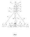
- Fig. 1
- ein erfindungsgemässes Notgestänge,
- Fig. 2
- einen erfindungsgemässen Mast,
- Fig. 3
- im Detail den oberen Teil des erfindungsgemässen Mastes,
- Fig. 4
- im Detail den unteren Teil des erfindungsgemässen Mastes und
- Fig. 5
- in Draufsicht eine Trägereinheit zur kugelgelenkigen Lagerung des erfindungsgemässen Mastes.
- Fig. 1
- an emergency linkage according to the invention,
- Fig. 2
- a mast according to the invention,
- Fig. 3
- in detail the upper part of the inventive mast,
- Fig. 4
- in detail the lower part of the inventive mast and
- Fig. 5
- in plan view a carrier unit for ball-jointed mounting of the inventive mast.
In Fig.1 ist eine mögliche Anordnung für ein erfindungsgemässes Notgestänge dargestellt. Ein Mast 1, der zu einem Trag-, Abspann- oder Endmast gehören kann, z.B. ein Gittermast aus Aluminium, ist hier mit drei Isolatoren 2 versehen. Es ist unter anderem möglich, hängende oder stehende Isolatoren aus beispielsweise Kunststoff, insbesondere Langstabisolatoren, einzusetzen. Für Spannungen über 220kV werden im Allgemeinen Kettenisolatoren aus z.B. hochfestem Kunststoff verwendet. An der Mastspitze angebracht ist ein Erdseil 3' zum Schutz der Leitung vor Blitzeinschlägen.
An den Isolatoren 2 sind Leiterseile 3 zur Übertragung elektrischer Energie, z.B. Strom, aufgehängt. Die Seile - Bündelleiter, insbesondere Zweierbündel, - sind Verbundseile aus Stahl und Aluminium mit einem Durchmesser von ca. 22.4 mm. Wird der Mast 1 als Notgestänge für eine beschädigte Freileitung aufgestellt, so werden, falls das möglich ist, die Leiterseile des schadhaften Mastes als Leiterseile 3 des Notgestänges verwendet. Können die "alten" Leiterseile nicht verwendet werden, so werden neue Phasenleiter am Notgestänge-Mast 1 angebracht und eine Brücke zur vorhandenen Leitung gebaut.
Am Mast 1 sind Einrichtungen zum Befestigen von Mastverankerungsmitteln, das sind hier Mast-Ankerseile 4 - insbesondere aus Stahl -, vorgesehen. Es können beliebig viele Befestigungsmöglichkeiten am Mast 1 eingerichtet sein, je nach den Gegebenheiten im Gelände und Anforderungen an die Freileitung bzw. den Freileitungsmast werden mehr oder weniger Verankerungen nötig sein. Es ist jedoch sinnvoll, den Mast 1 mit wenigstens vier Mast-Ankerseilen 4 an Ankereinheiten 6, hier Betonklötze, zu verankern. Die Mast-Ankerseile 4 können am Mast 1 z.B. etwa auf Höhe der Isolatoren 2 und der Mastspitze angebracht werden. Eine weitere Möglichkeit ist, dass ein Drehkranz 10 (Fig. 2) an der Mastspitze Befestigungseinrichtungen für Mast-Ankerseile 4 aufweist, wie z.B. Ösen, und die Verankerung des Mastes 1 mit den Ankereinheiten 6 am Drehkranz 10 erfolgt. Durch eine solche Verankerung des Mastbaums an dessen Spitze kann der restliche Mast 1 von Mast-Ankerseilen 4 frei gehalten werden, wodurch mehr Bewegungsfreiheit für Arbeiten am Mast 1 erreicht wird. Die Ankereinheiten 6 zur Abankerung des Mastes 1 sind meist mit einem Rahmen aus Winkeleisen ausgebildet, auf welchen Rahmen Klötze aus z.B. Beton oder Grauguss gestellt werden. Sie werden in kalkulierter Anzahl und Abständen zum Mast 1 aufgestellt. Die Ankerklötze sind so berechnet, dass sie die Last der Anker aufnehmen. Sie können noch mit Greifeinrichtungen oder Stützen, z.B. sogenannten "Bergstützen" oder "Erdhaken", ausgebildet sein, um zusätzlichen Halt im Boden zu erlangen.
Der Mast 1 ist aus gattungsgemäss leichtem Material gebaut, insbesondere Aluminium, sodass der gattungsgemäss leichte und hohe Mast 1 sehr schnell, d.h. z.B. in wenigen Stunden, aufgestellt werden kann.
Aufgestellt wird der Mast 1 auf einer dafür konzipierten Trägereinheit 5, die das Gewicht des Mastes 1 aufnimmt und ein Absinken in den Boden verhindert. Die Trägereinheit 5 ist hier als untere Platte 5' mit darauf angeordnetem wannenförmigen Aufsatz 5'' - eine Art Stahlwanne - dargestellt. Der Mast 1 weist an seinem unteren Ende eine kugelgelenkige Einrichtung auf, die in der Stahlwanne gelagert wird. Nach Versenken des Kugelgelenks 7 in der Wanne wird das Kugelgelenk 7 mit einem Deckel 8 versehen und so in der Wanne gehalten, z.B. indem der Deckel 8 angeschraubt wird. Die, z.B. wannenförmige, Trägereinrichtung 5 kann noch mit einem Flansch ausgepolstert werden. Diese Lagerung des Mastes 1 ist vorgesehen, um die von den Leiterseilen 3 ausgehenden Kräfte, z.B. Zugkräfte, vom Mast 1 auf die Ankereinheiten 6 zu verlagern.1 shows a possible arrangement for an emergency linkage according to the invention. A
At the
On
The
The
Fig. 2 zeigt den Mastbaum als solchen mit zusätzlichen Einrichtungen für Arbeits- oder Hilfsseile. Der Mast 1 ist hier als Gittermast aus Aluminium ausgebildet und aus einzelnen Mastsegmenten 1a zusammengesetzt. Die
Mastsegmente 1a werden miteinander verbunden, insbesondere ineinander gesetzt und verschraubt. Der Mast 1 weist an seinem unteren und oberen Ende als Einlauf- und Auslaufrolle ausgebildete Umlaufrollen 9',9" für ein Hilfsseil auf. Das Hilfs- oder Arbeitsseil wird vor Aufstellen des Mastes 1 über die als Einlaufrolle ausgebildete Umlaufrolle 9' innen durch den Mast 1 gezogen und über die als Auslaufrolle ausgebildete Umlaufrolle 9" aussen am Mast wieder zurückgeholt. Es dient als Arbeitsseil zum Transport von Bauteilen entlang der Höhe des Mastes 1. Der Mast 1 ist hier mit weiteren Einrichtungen - Umlaufrollen 9''' - für weitere Hilfsseile versehen. Es können beliebig viele Rollen am Mast 1 vorgesehen werden, z.B. in der Mitte für Vertikaltransporte von z.B. Leiterseilen von einem Mast 1 zum anderen. Die verschiedenen Umlaufrollen 9',9'',9''' sind so ausgebildet, dass sie um eine auf den Boden annähernd vertikale und zum Mast 1 annähernd parallele Achse drehbar sind, sodass Bauteile am gesamten Umfang des Mastes 1 transportiert werden können.Fig. 2 shows the mast tree as such with additional facilities for working or auxiliary ropes. The
In Fig. 3 dargestellt ist ein detaillierter Ausschnitt des oberen Teils des Mastes 1. Der Drehkranz 10 an der Mastspitze sieht Befestigungen für Mast-Ankerseile 4 vor. Ausserdem wird im Allgemeinen an der Mastspitze das Erdseil 3' angebracht. Mit der Umlaufrolle 9'', an der Mastspitze als Auslaufrolle bezeichnet, kann ein Hilfsseil zum Transport von nachträglich am Mast 1 zu installierenden Bauteilen am Mast 1 hochgezogen werden.Shown in Fig. 3 is a detailed section of the upper part of the
Fig. 4 zeigt im Detail einen Ausschnitt des unteren Mastteils mit einer als Einlaufrolle ausgebildeten Umlaufrolle 9' für ein Hilfs- und Arbeitsseil. Dargestellt ist auch die Trägereinheit 5, die sich hier aus einer Platte 5' mit darauf angeordneter Stahlwanne zusammensetzt. Die untere Platte 5' ist eine sogenannte Baggermatratze, darunter versteht man im Allgemeinen Konstruktionen aus Hartholz, die sich für vielfältigste Aufgaben eignen, wie z.B. als befahrbare Baustrasse, als Schiffsboden, als Fahrbahndecke auf Stahlträger einer Behelfsbrücke, als Umrandung eines Schüttgutlagers, als Schutz bei extrem belasteter Hartgummibereifung von Hebefahrzeugen, für Instandsetzungen zwischen Bahnschienen und überall dort, wo grosse Lasten auf schwierigem Untergrund schnell und kostengünstig bewegt werden müssen. Die obere Trägereinheit ist ein wannenförmiger Aufsatz 5'' zur Lagerung der Kugel am Mastende, welcher wannenförmige Aufsatz 5" Seitenstützen 5''' umfasst, die eine stabile Lagerung des Kugelgelenks 7 des Mastes 1 ermöglichen. Die Seitenstützen 5' ' ' sind insbesondere so ausgebildet und angeordnet, dass eine Art Mulde entsteht, in die das Kugelgelenk 7 versenkt werden kann. Dargestellt ist auch der Kugelgelenk-Deckel 8 mit Verschraubungen. Es versteht sich, dass die kugelgelenkige Lagerung des Mastes 1 auf alle Arten von Masten, wie z.B. Holz-, Stahlrohr- oder Stahlfachwerkmaste, angewandt werden kann.
Die Träger-Stahl-Einheit weist Befestigungsmöglichkeiten für Träger-Ankerseile 4' zur Verankerung der Träger-Stahl-Einheit an den Ankereinheiten 6 auf. Zu Baubeginn wird die Trägereinheit 5 aufgestellt und mit Trägerverankerungsmitteln, das sind meist Anker-Stahlseile, mit zwei oder mehreren Ankereinheiten 6 verbunden. So wird die Trägereinheit 5 fest und stabil in einer vorgegebenen Position gehalten.Fig. 4 shows in detail a section of the lower mast part with a trained as an inlet roller roller 9 'for a utility and working rope. Shown is also the
The support steel unit has mounting options for carrier anchor ropes 4 'for anchoring the carrier-steel unit to the
Fig. 5 zeigt den wannenförmigen Aufsatz 5" der Trägereinheit 5 in Draufsicht. Auf einer hier nicht dargestellten Baggermatratze ist eine hier mit Tragegriffen 11 ausgestattete Einrichtung, im Allgemeinen aus Stahl, für die kugelgelenkige Aufnahme des Freileitungsmasts vorgesehen. Die Einrichtung ist an der hier nicht gezeigten unteren Matratzen-Platte befestigt, z.B. verschraubt. Sie kann auch nur auf die untere Platte 5' gestellt, oder aber in die untere Platte 5' integriert sein, d.h. die Trägereinheit 5 könnte ein einstückiges Teil darstellen. In der Mitte der Stahlwanne - zwischen den Seitenstützen 5"' - dargestellt ist eine Art kreis- oder muldenförmige Lagerungseinheit zur Aufnahme des Kugelgelenks 7 des Mastes 1.
Zum Tragen des Mastes 1 benötigt wird eine Einrichtung, welche das Mastgewicht aufnehmen und verteilen kann und eine Möglichkeit zur kugelgelenkige Lagerung des Mastes 1 bereitstellt. Eine solche Einrichtung wird in diesem Ausführungsbeispiel durch eine nicht dargestellte Baggermatratze mit einem wannenförmigen Aufsatz 5'' aus Stahl mit Seitenstützen 5''', in deren Mitte das hier nicht gezeigte Kugelgelenk 7 des Mastes 1 in einer kreisförmigen Mulde versenkt und über einen Deckel 8 in der Mulde gehalten wird, bereitgestellt.5 shows a top view of the trough-shaped
To carry the
Claims (15)
Umlaufrollen (9',9'',9'''), zugeordnet werden, Leiterseile (3) und/oder gegebenenfalls Leiterseile der ausgefallenen Hochspannungsleitungen zum und/oder vom Mast (1) bewegt werden.Method according to one of claims 12 to 14, characterized in that on the basis of auxiliary ropes, which the mast (1), in particular by means of
Circulating rollers (9 ', 9'',9''') are assigned, conductor cables (3) and / or optionally ladder cables of the failed high voltage lines to and / or from the mast (1) to be moved.
Priority Applications (1)
| Application Number | Priority Date | Filing Date | Title |
|---|---|---|---|
| EP04030889A EP1677401A1 (en) | 2004-12-28 | 2004-12-28 | emergency boom for overhead lines |
Applications Claiming Priority (1)
| Application Number | Priority Date | Filing Date | Title |
|---|---|---|---|
| EP04030889A EP1677401A1 (en) | 2004-12-28 | 2004-12-28 | emergency boom for overhead lines |
Publications (1)
| Publication Number | Publication Date |
|---|---|
| EP1677401A1 true EP1677401A1 (en) | 2006-07-05 |
Family
ID=36215618
Family Applications (1)
| Application Number | Title | Priority Date | Filing Date |
|---|---|---|---|
| EP04030889A Withdrawn EP1677401A1 (en) | 2004-12-28 | 2004-12-28 | emergency boom for overhead lines |
Country Status (1)
| Country | Link |
|---|---|
| EP (1) | EP1677401A1 (en) |
Cited By (1)
| Publication number | Priority date | Publication date | Assignee | Title |
|---|---|---|---|---|
| EP2388878A3 (en) * | 2010-05-21 | 2014-04-09 | Taisto Siivonen | Transmission line tower |
Citations (4)
| Publication number | Priority date | Publication date | Assignee | Title |
|---|---|---|---|---|
| GB1409888A (en) * | 1971-12-30 | 1975-10-15 | Dillinger Stahlbau | Temporary mast structure |
| GB2274473A (en) * | 1993-01-20 | 1994-07-27 | Pressed Drums Ltd | Portable portal frame structure |
| JP2003018731A (en) * | 2001-06-28 | 2003-01-17 | Souki Kk | Telescopic power pole and cable installation method |
| US20040149970A1 (en) * | 2001-06-02 | 2004-08-05 | Sae-Won Kwon | Electric wire removing roller for lp insulator and power distribution method of construction |
-
2004
- 2004-12-28 EP EP04030889A patent/EP1677401A1/en not_active Withdrawn
Patent Citations (4)
| Publication number | Priority date | Publication date | Assignee | Title |
|---|---|---|---|---|
| GB1409888A (en) * | 1971-12-30 | 1975-10-15 | Dillinger Stahlbau | Temporary mast structure |
| GB2274473A (en) * | 1993-01-20 | 1994-07-27 | Pressed Drums Ltd | Portable portal frame structure |
| US20040149970A1 (en) * | 2001-06-02 | 2004-08-05 | Sae-Won Kwon | Electric wire removing roller for lp insulator and power distribution method of construction |
| JP2003018731A (en) * | 2001-06-28 | 2003-01-17 | Souki Kk | Telescopic power pole and cable installation method |
Non-Patent Citations (1)
| Title |
|---|
| PATENT ABSTRACTS OF JAPAN vol. 2003, no. 05 12 May 2003 (2003-05-12) * |
Cited By (1)
| Publication number | Priority date | Publication date | Assignee | Title |
|---|---|---|---|---|
| EP2388878A3 (en) * | 2010-05-21 | 2014-04-09 | Taisto Siivonen | Transmission line tower |
Similar Documents
| Publication | Publication Date | Title |
|---|---|---|
| EP2909476B1 (en) | Supply frame for a tower, tower with a supply frame and method for erecting a supply frame in the interior of a tower | |
| EP2311725B1 (en) | Floating support with improved bracing | |
| EP0960986A2 (en) | Process and device for the construction of tall, hollow, towerlike structures of two hundred meters height and more, specially wind generator towers | |
| CN103437296A (en) | Steel tube arch bridge towerless buckling three-section type double-rib folding hoisting construction method | |
| US10669994B1 (en) | Multi-column wind turbine tower and erection method | |
| WO1998009072A1 (en) | Masts for wind power installations | |
| EP2447420B1 (en) | Mast | |
| DE202015003668U1 (en) | Substructure for a mast and mast system | |
| EP1677401A1 (en) | emergency boom for overhead lines | |
| WO2014005897A1 (en) | System for retrofitting local energy modules in rail networks | |
| DE102012021697B4 (en) | Support system for the stabilization of at least one mast | |
| EP2805846B1 (en) | Overhead mast and overhead system for electrically driven vehicles | |
| DE19803954A1 (en) | Mast raising procedure for use in high voltage overhead line construction | |
| DE10215915A1 (en) | Device for raising, attaching loads to tower, mast structures for assembling wind power systems has vertical, positively guided system with two lifting carriages moved by dual action lifting cylinder | |
| DE202020100626U1 (en) | Mast, overhead line arrangement and overhead line system | |
| WO2021028441A1 (en) | Assembly crossbeam and method for drawing in cable-like elements, in particular tendons, along a tower of a wind turbine | |
| DE102017206789B4 (en) | Bridge construction, especially for a residential bridge | |
| EP0802324A1 (en) | Wind turbine installation | |
| DE10005912C2 (en) | Method of assembling a protective network for attaching or removing high-voltage lines between pylons | |
| DE102019124123A1 (en) | tower | |
| DE202010011444U1 (en) | Reusable foundation for an overhead line, preferably for a catenary | |
| DE102010023263A1 (en) | Tower for wind energy plant, has tower wall carried out on multiple steel rod segments, where lower steel tube segment is formed as adaptor piece to foundation in installation position | |
| DE102011116375A1 (en) | Overhead line tower e.g. suspension tower, for carrying e.g. electrical lines, has suspending device for suspending or carrying electrical line, and support device supporting wind turbines, which produce electrical energy from wind force | |
| DE202020100625U1 (en) | Security system and security arrangement for securing an overhead line | |
| DE202011103375U1 (en) | Modified cable protection crossbar |
Legal Events
| Date | Code | Title | Description |
|---|---|---|---|
| PUAI | Public reference made under article 153(3) epc to a published international application that has entered the european phase |
Free format text: ORIGINAL CODE: 0009012 |
|
| AK | Designated contracting states |
Kind code of ref document: A1 Designated state(s): AT BE BG CH CY CZ DE DK EE ES FI FR GB GR HU IE IS IT LI LT LU MC NL PL PT RO SE SI SK TR |
|
| AX | Request for extension of the european patent |
Extension state: AL BA HR LV MK YU |
|
| 17P | Request for examination filed |
Effective date: 20061229 |
|
| AKX | Designation fees paid |
Designated state(s): AT BE BG CH CY CZ DE DK EE ES FI FR GB GR HU IE IS IT LI LT LU MC NL PL PT RO SE SI SK TR |
|
| RAP1 | Party data changed (applicant data changed or rights of an application transferred) |
Owner name: WEGERMANN, MICHAEL |
|
| RAP1 | Party data changed (applicant data changed or rights of an application transferred) |
Owner name: IEF GENERALUNTERNEHMUNG AG |
|
| STAA | Information on the status of an ep patent application or granted ep patent |
Free format text: STATUS: THE APPLICATION IS DEEMED TO BE WITHDRAWN |
|
| 18D | Application deemed to be withdrawn |
Effective date: 20130629 |