EP1677053A1 - Outdoor unit of air conditioner - Google Patents
Outdoor unit of air conditioner Download PDFInfo
- Publication number
- EP1677053A1 EP1677053A1 EP04748193A EP04748193A EP1677053A1 EP 1677053 A1 EP1677053 A1 EP 1677053A1 EP 04748193 A EP04748193 A EP 04748193A EP 04748193 A EP04748193 A EP 04748193A EP 1677053 A1 EP1677053 A1 EP 1677053A1
- Authority
- EP
- European Patent Office
- Prior art keywords
- fan motor
- outdoor unit
- disposed
- bellmouth
- front panel
- Prior art date
- Legal status (The legal status is an assumption and is not a legal conclusion. Google has not performed a legal analysis and makes no representation as to the accuracy of the status listed.)
- Withdrawn
Links
Images


Classifications
-
- F—MECHANICAL ENGINEERING; LIGHTING; HEATING; WEAPONS; BLASTING
- F24—HEATING; RANGES; VENTILATING
- F24F—AIR-CONDITIONING; AIR-HUMIDIFICATION; VENTILATION; USE OF AIR CURRENTS FOR SCREENING
- F24F1/00—Room units for air-conditioning, e.g. separate or self-contained units or units receiving primary air from a central station
- F24F1/06—Separate outdoor units, e.g. outdoor unit to be linked to a separate room comprising a compressor and a heat exchanger
- F24F1/46—Component arrangements in separate outdoor units
-
- F—MECHANICAL ENGINEERING; LIGHTING; HEATING; WEAPONS; BLASTING
- F24—HEATING; RANGES; VENTILATING
- F24F—AIR-CONDITIONING; AIR-HUMIDIFICATION; VENTILATION; USE OF AIR CURRENTS FOR SCREENING
- F24F1/00—Room units for air-conditioning, e.g. separate or self-contained units or units receiving primary air from a central station
- F24F1/06—Separate outdoor units, e.g. outdoor unit to be linked to a separate room comprising a compressor and a heat exchanger
- F24F1/60—Arrangement or mounting of the outdoor unit
-
- F—MECHANICAL ENGINEERING; LIGHTING; HEATING; WEAPONS; BLASTING
- F24—HEATING; RANGES; VENTILATING
- F24F—AIR-CONDITIONING; AIR-HUMIDIFICATION; VENTILATION; USE OF AIR CURRENTS FOR SCREENING
- F24F1/00—Room units for air-conditioning, e.g. separate or self-contained units or units receiving primary air from a central station
- F24F1/06—Separate outdoor units, e.g. outdoor unit to be linked to a separate room comprising a compressor and a heat exchanger
- F24F1/38—Fan details of outdoor units, e.g. bell-mouth shaped inlets or fan mountings
-
- F—MECHANICAL ENGINEERING; LIGHTING; HEATING; WEAPONS; BLASTING
- F24—HEATING; RANGES; VENTILATING
- F24F—AIR-CONDITIONING; AIR-HUMIDIFICATION; VENTILATION; USE OF AIR CURRENTS FOR SCREENING
- F24F13/00—Details common to, or for air-conditioning, air-humidification, ventilation or use of air currents for screening
-
- F—MECHANICAL ENGINEERING; LIGHTING; HEATING; WEAPONS; BLASTING
- F24—HEATING; RANGES; VENTILATING
- F24F—AIR-CONDITIONING; AIR-HUMIDIFICATION; VENTILATION; USE OF AIR CURRENTS FOR SCREENING
- F24F13/00—Details common to, or for air-conditioning, air-humidification, ventilation or use of air currents for screening
- F24F13/20—Casings or covers
-
- F—MECHANICAL ENGINEERING; LIGHTING; HEATING; WEAPONS; BLASTING
- F24—HEATING; RANGES; VENTILATING
- F24F—AIR-CONDITIONING; AIR-HUMIDIFICATION; VENTILATION; USE OF AIR CURRENTS FOR SCREENING
- F24F13/00—Details common to, or for air-conditioning, air-humidification, ventilation or use of air currents for screening
- F24F13/20—Casings or covers
- F24F2013/205—Mounting a ventilator fan therein
Definitions
- the present invention relates to an outdoor unit of an air conditioner.
- An outdoor unit of an air conditioner is usually disposed with a fan motor that rotatably drives a blower fan, and the fan motor is attached to the outdoor unit via a fan motor base. It is preferable for the fan motor base to be fixed to a top panel and a bottom panel in order to ensure strength. Conventionally, there are many instances where the fan motor base fixed to the top panel and the bottom panel is disposed upstream of the blower fan, and the fan motor base is disposed between an outdoor heat exchanger and the blower fan and fixed to the top panel and the bottom panel.
- the outdoor unit of the air conditioner is disposed with a bellmouth.
- the bellmouth is a member that guides the airflow generated by the blower fan and is disposed such that it covers the periphery of the blower fan. Also, because the bellmouth is disposed from the vicinity of the blower fan to downstream of the blower fan in order to guide the air, there are many instances where the bellmouth is fixed to a front panel that is downstream of the blower fan and disposed on the front side of the outdoor unit (see Patent Document 1).
- JP-A Japanese Patent Application Publication No. 2003-124649
- An outdoor unit of an air conditioner pertaining to a first invention is disposed with an outdoor unit casing, a blower fan, a bellmouth, a fan motor and a fan motor base.
- the outdoor unit casing includes a top panel disposed on a top side, a bottom panel disposed on a bottom side, and a front panel that is disposed on a front side and in which air blowout holes are disposed.
- the blower fan is housed in the outdoor unit casing and generates an airflow that is blown out through the blowout holes in the front panel.
- the bellmouth guides the airflow generated by the blower fan.
- the fan motor rotatably drives the blower fan.
- the fan motor is fixed to the fan motor base, and the fan motor base includes an upper portion that is fixed to a front portion of the top panel and a lower portion that is fixed to a front portion of the bottom panel, and is disposed on a front side of the blower fan.
- the bellmouth and the fan motor base are positioned with the front panel as a reference.
- the fan motor and the fan motor base are strongly attached to the outdoor unit casing because the upper portion and lower portion of the fan motor base are respectively fixed to the top panel front portion and the bottom panel front portion. Also, error in the dimension of the disposition of the fan motor base and the bellmouth can be reduced because the fan motor base and the bellmouth are both positioned with the front panel as a reference. Consequently, in the outdoor unit of the air conditioner, it is easy to reduce the clearance between the bellmouth and the blower fan, and wind performance can be improved.
- An outdoor unit of an air conditioner pertaining to a second invention is the outdoor unit of the air conditioner of the first invention, wherein the fan motor base and the bellmouth are disposed along an inner surface of the front panel.
- the fan motor base and the bellmouth are easily positioned with the front panel as a reference because the fan motor base and the bellmouth are disposed along the inner surface of the front panel.
- An outdoor unit of an air conditioner pertaining to a third invention is the outdoor unit of the air conditioner of the second invention, wherein the fan motor base is disposed between the bellmouth and the front panel and internally touches the bellmouth and the front panel.
- the positioning of the fan motor and the bellmouth is easier because the fan motor base is disposed between the bellmouth and the front panel and internally touches the bellmouth and the front panel. For this reason, in the outdoor unit of this air conditioner, it is easier to reduce the clearance between the bellmouth and the blower fan, and wind performance can be easily improved.
- An outdoor unit of an air conditioner pertaining to a fourth invention is the outdoor unit of the air conditioner of any of the first to third inventions, wherein the front panel is a member made of resin.
- the manufacturing cost can be reduced in comparison to a case where the front panel is manufactured by plate metal or the like because the front panel is a member made of resin. Also, when the front panel is a member made of resin when the fan motor base is to be attached to the front panel, the strength of the portion to which the fan motor base is to be attached becomes a problem, but in the outdoor unit of this air conditioner, strength is also ensured because the upper portion of the fan motor base is fixed to the top panel front portion and the lower portion is fixed to the bottom panel front portion.
- An outdoor unit of an air conditioner pertaining to a fifth invention is the outdoor unit of the air conditioner of any of the first to fourth inventions, wherein the blowout holes in the front panel are configured by plural slits partitioned by a grating. Also, the fan motor base and the grating are disposed such that the blowout resistance of the airflow is reduced.
- the fan motor base and the grating are disposed such that the blowout resistance of the airflow is reduced. For this reason, an increase in the blowout resistance of the air can be suppressed and wind performance can be improved.
- An outdoor unit of an air conditioner pertaining to a sixth invention is the outdoor unit of the air conditioner of the fifth invention, wherein the fan motor base includes vertical members.
- the vertical members are disposed such that they extend in a vertical direction when seen in front view and overlap the grating.
- the vertical members of the fan motor base are disposed such that they extend in the vertical direction when seen in front view and overlap the grating. For this reason, an increase in the blowout resistance of the airflow due to the fan motor base can be suppressed. For this reason, an increase in the blowout resistance of the air can be suppressed and wind performance can be improved.
- An outdoor unit of an air conditioner pertaining to a seventh invention is the outdoor unit of the air conditioner of any of the first to sixth inventions, wherein the front panel, the bellmouth, the blower fan, the fan motor and the fan motor base are modulized.
- productivity is improved and positioning of the fan motor base and the bellmouth with the front panel as a reference is easy because the front panel, the bellmouth, the blower fan, the fan motor and the fan motor base are modulized.
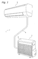
- FIG. 1 shows an external view of an air conditioner 1 in which an embodiment of the present invention has been adopted.
- the air conditioner 1 is disposed with an indoor unit 2, which is attached to an indoor wall surface or the like, and an outdoor unit 3, which is disposed outdoors.
- An indoor heat exchanger 70 is housed inside the indoor unit 2
- an outdoor heat exchanger 30 is housed inside the outdoor unit 3
- a refrigerant circuit is configured as a result of the heat exchangers 30 and 70 being connected by a refrigerant pipe 4.
- FIG. 2 shows the configuration of the refrigerant circuit of the air conditioner 1.
- the refrigerant circuit is mainly configured by the indoor heat exchanger 70, an accumulator 31, a compressor 32, a four-way switch valve 33, the outdoor heat exchanger 30 and an electric expansion valve 34.
- the indoor heat exchanger 70 disposed in the indoor unit 2 conducts heat exchange with the air contacting it.
- a cross-flow fan 71 for taking in indoor air and discharging, to the indoors, air after heat exchange has been conducted through the indoor heat exchanger 70 is disposed in the indoor unit 2.
- the cross-flow fan 71 is configured in a long and narrow circular cylinder shape and is disposed such that its center axis is parallel to the horizontal direction.
- the cross-flow fan 71 is rotatably driven by an indoor fan motor 72 disposed inside the indoor unit 2.
- the compressor 32 Disposed in the outdoor unit 3 are the compressor 32, the four-way switch valve 33 connected to the discharge side of the compressor 32, the accumulator 31 connected to the intake side of the compressor 32, the outdoor heat exchanger 30 connected to the four-way switch valve 33, and the electric expansion valve 34 connected to the outdoor heat exchanger 30.
- the electric expansion valve 34 is connected to a pipe 41 via a filter 35 and a liquid closure valve 36, and is connected to one end of the indoor heat exchanger 70 via the pipe 41.
- the four-way switch valve 33 is connected to a pipe 42 via a gas closure valve 37, and is connected to the other end of the indoor heat exchanger 70 via the pipe 42.
- the pipes 41 and 42 correspond to the refrigerant pipe 4 of FIG 1.
- a blower fan 38 for discharging, to the outside, air after heat exchange by the outdoor heat exchanger 30 is disposed in the outdoor unit 3.
- the blower fan 38 is rotatably driven by a fan motor 39.
- the outdoor unit 3 is disposed with an outdoor unit casing 5 (see FIG 1), the compressor 32, the four-way switch valve 33, the electric expansion valve 34 (see FIG. 2), the closure valves 36 and 37, a reactor 40, an electrical component box 43, the outdoor heat exchanger 30, the blower fan 38, the fan motor 39, a fan motor base 44, and a bellmouth 45.
- the outdoor unit casing 5 mainly includes a top panel 50, a bottom panel 51, a front panel 52, a left side panel 53, a right side panel 54, a closure valve cover 55, and a partition panel 56.
- the top panel 50 is disposed on the top side of the outdoor unit 3 and covers the top side of the interior space of the outdoor unit 3.
- the top panel 50 is formed by plate metal.
- the edge of the top panel 50 is bent downward in the vertical direction, and a screw hole is disposed, as fixing means for fixing a later-described front panel assembly 6, in a top panel front portion 58 positioned at the front side of the bent portion.
- the bottom panel 51 is disposed on the bottom side of the outdoor unit 3 and covers the bottom of the interior space of the outdoor unit 3.
- the bottom panel 51 is formed by plate metal.
- the edge of the bottom panel 51 is bent upward in the vertical direction, and a screw hole is disposed, as fixing means for fixing the front panel assembly 6, in a bottom panel front portion 57 positioned at the front side of the bent portion.
- the front panel 52 is disposed on the front side of the outdoor unit 3 and covers the front side of the interior space of the outdoor unit 3. Blowout holes 59, through which air is blown out, are disposed in the front panel such that the air to be blown out passes from the inside of the outdoor unit 3 to the outside.
- the front panel 52 will be described in greater detail later.
- the left side panel 53 is disposed on the left side of the outdoor unit 3 and covers the left side of the interior space of the outdoor unit 3.
- the left side panel 53 is formed by plate metal.
- the right side panel 54 covers the right side of the interior space of the outdoor unit 3.
- the right side panel 54 is formed by plate metal.
- the closure valve cover 55 which is made of resin, is attached to the right side, i.e., the outer side, of the right side panel 54.
- the partition panel 56 is disposed perpendicular to the bottom panel 51 and partitions the interior space of the outdoor unit 3 into two spaces at the left and right.
- the space positioned at the left side of the partition panel 56 serves as a ventilation chamber and is a space through which passes air that is taken in from the outside of the outdoor unit 3, passes through the outdoor heat exchanger 30 and is to be discharged to the outdoors.
- the space positioned at the right side of the partition panel 56 serves as a machine chamber and is a space that is blocked off to a certain extent from the ventilation chamber. Most of the machine parts are housed in the machine chamber.
- FIG. 4 is a schematic perspective view showing part of the configuration of the outdoor unit 3, and the front panel 52 and other members have been omitted in order to facilitate understanding.
- the compressor 32 is disposed in the machine chamber and is fixed to the bottom panel 51.
- the four-way switch valve 33 is disposed in front of the compressor 32.
- the electric expansion valve 34 (see FIG. 2) is disposed in the machine chamber similarly to the compressor 32 and is disposed at the side of the compressor 32.
- the closure valves 36 and 37 are disposed below the right side panel 54.
- the reactor 40 is disposed in the side wall of the partition panel 56 in the machine chamber.
- the electrical component box 43 is disposed in the upper portion of the machine chamber.
- Control circuits such as a microcomputer chip for conducting control of various devices and a memory in which a control program, and other circuit components are stored are housed in the electrical component box 43 and are connected by a harness or the like to the compressor 32, the four-way switch valve 33, the electric expansion valve 34 and the reactor 40.
- the outdoor heat exchanger 30 is disposed in the ventilation chamber and conducts heat exchange with the air passing therethrough.
- the outdoor heat exchanger 30 is disposed along the left side portion from the rear portion of the ventilation chamber and has a substantially L-shaped shape.
- the blower fan 38, the fan motor 39, the fan motor base 44 and the bellmouth 45 are disposed in the ventilation chamber and configure the front panel assembly 6, which is modulized together with the front panel 52.
- the configuration of the front panel assembly 6 will be described in detail below.
- the front panel assembly 6 is configured as a result of the front panel 52, the blower fan 38, the fan motor 39, the fan motor base 44 and the bellmouth 45 being modulized with the front panel 52 as a reference.
- the front panel 52 is formed from a resin such as polypropylene and disposed on the front side of the outdoor unit 3.
- the front panel 52 is disposed on the front side of the bellmouth 45 and the fan motor base 44. Screw holes are respectively disposed in the upper end and the lower end of the front panel 52.
- screws are passed through the screw holes in the front panel 52 and the screw holes disposed in the top panel front portion 58 and the bottom panel front portion 57, so that the front panel 52 and the top panel 50, and the front panel 52 and the bottom panel 51, are screwed together.
- a grating 60 (see FIG.
- a circular solid portion 61 in which the blowout holes 59 are not disposed, is disposed in the vicinity of the center of the portion in which the blowout holes 59 are disposed.
- the solid portion 61 is disposed at a position that overlaps the fan motor 39 when seen in front view.
- the blower fan 38 is a propeller fan including plural blades and is positioned downstream of the outdoor heat exchanger 30. As shown in FIG. 5, the blower fan 38 is disposed in the substantial center of the ventilation chamber when seen in front view. FIG. 5 is a front view showing part of the configuration of the outdoor unit 3, and the bellmouth 45 and other members have been omitted in order to facilitate understanding. Also, as shown in FIG. 4, a fan motor housing 62 is disposed in the center of the blower fan 38. The fan motor housing 62 has a hollow circular cylinder shape whose bottom side is open, and in a state where the blower fan 38 is housed in the outdoor unit 3, this opening faces the front side, i.e., downstream.
- the fan motor 39 is inserted from the front side and housed in the fan motor housing 62.
- the blower fan 38 is fixed to a rotating shaft of the fan motor 39 and is rotatably driven by the fan motor 39 around an axis parallel to the front-rear direction.
- the airflow generated by the blower fan 38 is taken into the ventilation chamber from the rear side of the outdoor unit 3, passes through the outdoor heat exchanger 30, the bellmouth 45 and the blowout holes 59 in the front panel 52, and is discharged to the outside of the outdoor unit 3.
- the bellmouth 45 shown in FIG. 3 and FIG. 6 is formed from a resin such as polypropylene and forms an air path that guides the airflow generated by the blower fan 38 and blown out to the outdoors.
- the bellmouth 45 is fixed to the inner surface of the front panel 52 along the inner surface of the front panel 52 and disposed such that it covers the periphery of the blower fan 38.
- the airflow generated by the blower fan 38 is taken into the ventilation chamber from the outside through the rear side of the outdoor unit 3, passes through the outdoor heat exchanger 30, passes through the opening in the bellmouth 45 and the blowout holes 59 in the front panel 52, and is blown out to the outside of the outdoor unit 3.
- the bellmouth 45 includes a circular cylinder portion 63 and a planar portion 64.
- the circular cylinder portion 63 has a thin, hollow, circular cylinder shape.
- the circular cylinder portion 63 is disposed on the rear portion of the bellmouth 45 and configures a circular opening through which passes the airflow generated by the blower fan 38.
- the circular cylinder portion 63 is disposed such that the center of the opening coincides with the rotational axis of the blower fan 38. Part of the front side of the blower fan 38 is inserted inside the circular cylinder portion 63 (see FIG. 6).
- the planar portion 64 is a thin member having a rectangular outer shape when seen in front view and is provided to the front portion of the bellmouth 45.
- the majority of the area of the planar portion 64 is occupied by a circular opening.
- the edge of this opening is continuous with the circular cylinder portion 63, such that the air generated by the blower fan 38 passes therethrough.
- Screw holes are disposed in the upper end and the lower end of the planar portion 64, and the planar portion 64 is fixed to the inner surface of the front panel 52 as a result of screwing. Consequently, the bellmouth 45 is attached to the inner surface of the front panel 52 and positioned with the front panel 52 as a reference.
- the fan motor 39 is inserted into the circular cylinder portion 63 of the blower fan 38 from the front side and attached to the blower fan 38.
- the fan motor 39 is disposed such that its rotational axis is positioned parallel to the front-rear direction of the outdoor unit 3.
- the rotating shaft of the fan motor 39 is fixed to the rotational center of the blower fan 38, and the fan motor 39 rotatably drives the blower fan 38.
- the fan motor base 44 is a member to which the fan motor 39 is fixed and which supports the fan motor 39, and is formed from plate metal. As shown in FIG. 5 and FIG. 6, the fan motor base 44 is disposed in front of the blower fan 38, and is disposed in front of the fan motor 39 and in front of the bellmouth 45. The fan motor base 44 is disposed along the inner surface of the front panel 52 and fixed to the inner surface of the front panel 52. Consequently, the fan motor base 44 is positioned with the front panel 52 as a reference. In a state where the front panel assembly 6 has been assembled, the fan motor base 44 is positioned between the front panel 52 and the bellmouth 45 and internally touches the front panel 52 and the bellmouth 45. As shown in FIG.
- the fan motor base 44 has a thin shape having a rectangular outer contour that is long in the vertical direction when seen in front view and extends to a height that is substantially the same as the top side and the bottom side of the outdoor unit 3. That is, both the upper and lower ends of the fan motor base 44 extend to the same height as both the upper and lower ends of the front panel 52. Screw holes are respectively disposed in the upper end and the lower end of the fan motor base 44. The screw holes are disposed such that in a state where the front panel assembly 6 has been assembled, they coincide with the screw holes disposed in the upper end and lower end of the front panel 52.
- the upper end of the front panel 52 and the upper end of the fan motor base 44 are screwed to the top panel front portion 58 by a common screw. Also, the lower end of the front panel 52 and the lower end of the fan motor base 44 are fixed to the bottom panel front portion 57 by a common screw.
- Plural rectangular openings are arranged in the vertical direction when seen in front view and disposed in the fan motor base 44. These openings have a left-right width that is slightly smaller than the left-right width of the fan motor 44, and are disposed in proximity in the vertical direction. Consequently, the fan motor base 44 is configured by two vertical members 65 in long and narrow shape that extend in the vertical direction and by plural horizontal members 66 that have narrow shapes and extend in the left-right direction, such that the fan motor base 44 has a shape where the horizontal members 66 connect the vertical members 65 disposed apart from each other. For this reason, the surface area of the fan motor base 44 when seen in front view is small and the airflow resistance resulting from the blower fan 38 is reduced. Also, as shown in FIG.
- the fan motor base 44 is disposed such that in a state where the front panel assembly 6 has been assembled, the vertical members 65 of the fan motor base 44 and part of the grating 60 of the front panel 52 overlap. For this reason, the airflow resistance resulting from the blower fan 38 is further reduced.
- the fan motor base 44 is fixed to the top panel 50 and the bottom panel 51 in order to ensure strength
- the fan motor base 44 is disposed between the fan motor 38 and the outdoor heat exchanger 30.
- the fan motor base 44, the fan motor 39 and the blower fan 38 are sequentially fixed from the rear side b and the lower end of the fan motor base 44 is fixed to the bottom panel 51.
- the front panel 52 and the bellmouth 45 are fixed separately from these.
- the blower fan is inserted into the opening in the bellmouth 45 and the front panel 52 is fixed to the bottom panel 51.
- the bellmouth 45 is positioned with the front panel 52 as a reference. For this reason, it is difficult to improve the dimensional precision of the position of the blower fan 38 and the bellmouth 45, and it is difficult to reduce the clearance between the inner peripheral surface of the opening in the bellmouth 45 and the outer periphery of the blower fan 38. In order to improve wind performance in the outdoor unit 3, it is preferable to reduce the clearance between the bellmouth 45 and the blower fan 38, but in the conventional outdoor unit 3 of the air conditioner 1, it has been difficult to reduce this clearance while ensuring the strength of the attachment portion of the fan motor base 44.
- the fan motor base 44, the bellmouth 45 and the front panel 52 are integrally combined with the front panel 52 as a reference. For this reason, the fan motor base 44 and the bellmouth 45 are respectively positioned with the front panel 52 as a reference. Consequently, the dimensional precision of the position of the blower fan 38 and the bellmouth 45 is improved, and it is easy to center the blower fan 38 and the bellmouth 45. Thus, it is easy to reduce the clearance between the inner peripheral surface of the opening in the bellmouth 45 and the outer periphery of the blower fan 38, and an improvement in the wind performance and a reduction of variations in the wind performance are possible.
- the dimensional precision of the position of the blower fan 38 and the bellmouth 45 is improved. For this reason, it is easy to overlap the grating 60 of the front panel 52 and the vertical members 65 of the fan motor base 44 at the same position when seen in front view. For this reason, the airflow resistance of the airflow that passes through the ventilation chamber and the front panel 52 and is blown out can be reduced.
- the blower fan 38, the fan motor 39, the fan motor base 44, the bellmouth 45 and the front panel 52 are modulized, and these constituent parts for ventilation are compactly consolidated. For this reason, a reduction in cost is possible. Also, the wiring procedure of connecting these constituent parts can be simplified. Thus, in the outdoor unit 3 of the air conditioner 1, productivity is improved.
- the front panel 52 is formed by resin, but the front panel 52 may also be formed by plate metal. However, from the standpoints of cost reduction and weight reduction, it is preferable for the front panel 52 to be formed by resin. Also, in the present invention, because the fan motor base 44 is fixed not only to the front panel 52 but also to the bottom panel 51 and the top panel 50, it is easy to ensure the necessary strength even if the front panel 52 is formed by resin.
- airflow resistance is reduced as a result of the grating 60 of the front panel 52 and the vertical members 65 of the fan motor base 44 being positioned such that they overlap when seen in front view, but airflow resistance may also be reduced by other dispositions.
- the grating 60 and the horizontal members 66 may be positioned such that they overlap when seen in front view, and a reduction in airflow resistance is also possible even if the slits and the fan motor base are symmetrically disposed when seen in front view.
- the dimensional precision of the disposition is improved because the fan motor base 44 is positioned with the front panel 52 as a reference, and the outdoor unit 3 of the above-described disposition can be manufactured more precisely.
- the present invention is suited for improving wind performance in an outdoor unit of an air conditioner because it is easy to reduce the clearance between the bellmouth and the blower fan.
Landscapes
- Engineering & Computer Science (AREA)
- Chemical & Material Sciences (AREA)
- Combustion & Propulsion (AREA)
- Mechanical Engineering (AREA)
- General Engineering & Computer Science (AREA)
- Other Air-Conditioning Systems (AREA)
Abstract
Description
- The present invention relates to an outdoor unit of an air conditioner.
- An outdoor unit of an air conditioner is usually disposed with a fan motor that rotatably drives a blower fan, and the fan motor is attached to the outdoor unit via a fan motor base. It is preferable for the fan motor base to be fixed to a top panel and a bottom panel in order to ensure strength. Conventionally, there are many instances where the fan motor base fixed to the top panel and the bottom panel is disposed upstream of the blower fan, and the fan motor base is disposed between an outdoor heat exchanger and the blower fan and fixed to the top panel and the bottom panel.
- There are also many instances where the outdoor unit of the air conditioner is disposed with a bellmouth. The bellmouth is a member that guides the airflow generated by the blower fan and is disposed such that it covers the periphery of the blower fan. Also, because the bellmouth is disposed from the vicinity of the blower fan to downstream of the blower fan in order to guide the air, there are many instances where the bellmouth is fixed to a front panel that is downstream of the blower fan and disposed on the front side of the outdoor unit (see Patent Document 1).
- Japanese Patent Application Publication (JP-A) No. 2003-124649
- In an outdoor unit of an air conditioner disposed with a fan motor base that is fixed to the top panel and the bottom panel in this manner, there are many instances where the fan motor base and the bellmouth are disposed apart from each other. However, in an attachment structure where the fan motor base and the bellmouth are disposed apart from each other, it is difficult to reduce the clearance between the bellmouth and the blower fan. That is, because the fan motor base and the bellmouth are disposed apart from each other, it is difficult to reduce dimensional error in the disposition of the fan motor base and the bellmouth, and it is necessary to additionally ensure clearance in view of some error. In order to improve the wind performance of the bellmouth, it is preferable to reduce the clearance between the bellmouth and the blower fan, but in an attachment structure such as described above, it is difficult to reduce this clearance and difficult to improve the wind performance.
- It is an object of the present invention to provide an outdoor unit of an air conditioner that can improve wind performance.
- An outdoor unit of an air conditioner pertaining to a first invention is disposed with an outdoor unit casing, a blower fan, a bellmouth, a fan motor and a fan motor base. The outdoor unit casing includes a top panel disposed on a top side, a bottom panel disposed on a bottom side, and a front panel that is disposed on a front side and in which air blowout holes are disposed. The blower fan is housed in the outdoor unit casing and generates an airflow that is blown out through the blowout holes in the front panel. The bellmouth guides the airflow generated by the blower fan. The fan motor rotatably drives the blower fan. The fan motor is fixed to the fan motor base, and the fan motor base includes an upper portion that is fixed to a front portion of the top panel and a lower portion that is fixed to a front portion of the bottom panel, and is disposed on a front side of the blower fan. The bellmouth and the fan motor base are positioned with the front panel as a reference.
- In the outdoor unit of this air conditioner, the fan motor and the fan motor base are strongly attached to the outdoor unit casing because the upper portion and lower portion of the fan motor base are respectively fixed to the top panel front portion and the bottom panel front portion. Also, error in the dimension of the disposition of the fan motor base and the bellmouth can be reduced because the fan motor base and the bellmouth are both positioned with the front panel as a reference. Consequently, in the outdoor unit of the air conditioner, it is easy to reduce the clearance between the bellmouth and the blower fan, and wind performance can be improved.
- An outdoor unit of an air conditioner pertaining to a second invention is the outdoor unit of the air conditioner of the first invention, wherein the fan motor base and the bellmouth are disposed along an inner surface of the front panel.
- In the outdoor unit of this air conditioner, the fan motor base and the bellmouth are easily positioned with the front panel as a reference because the fan motor base and the bellmouth are disposed along the inner surface of the front panel. Thus, in the outdoor unit of this air conditioner, it is easy to reduce the clearance between the bellmouth and the flower fan, and wind performance can be improved.
- An outdoor unit of an air conditioner pertaining to a third invention is the outdoor unit of the air conditioner of the second invention, wherein the fan motor base is disposed between the bellmouth and the front panel and internally touches the bellmouth and the front panel.
- In the outdoor unit of this air conditioner, the positioning of the fan motor and the bellmouth is easier because the fan motor base is disposed between the bellmouth and the front panel and internally touches the bellmouth and the front panel. For this reason, in the outdoor unit of this air conditioner, it is easier to reduce the clearance between the bellmouth and the blower fan, and wind performance can be easily improved.
- An outdoor unit of an air conditioner pertaining to a fourth invention is the outdoor unit of the air conditioner of any of the first to third inventions, wherein the front panel is a member made of resin.
- In the outdoor unit of this air conditioner, the manufacturing cost can be reduced in comparison to a case where the front panel is manufactured by plate metal or the like because the front panel is a member made of resin. Also, when the front panel is a member made of resin when the fan motor base is to be attached to the front panel, the strength of the portion to which the fan motor base is to be attached becomes a problem, but in the outdoor unit of this air conditioner, strength is also ensured because the upper portion of the fan motor base is fixed to the top panel front portion and the lower portion is fixed to the bottom panel front portion.
- An outdoor unit of an air conditioner pertaining to a fifth invention is the outdoor unit of the air conditioner of any of the first to fourth inventions, wherein the blowout holes in the front panel are configured by plural slits partitioned by a grating. Also, the fan motor base and the grating are disposed such that the blowout resistance of the airflow is reduced.
- Usually, when the fan motor base is disposed in the flow of the airflow resulting from the blower fan, there is the potential for the blowout resistance of the air to increase due to the fan motor base and for the wind performance to drop.
- However, in the outdoor unit of this air conditioner, the fan motor base and the grating are disposed such that the blowout resistance of the airflow is reduced. For this reason, an increase in the blowout resistance of the air can be suppressed and wind performance can be improved.
- An outdoor unit of an air conditioner pertaining to a sixth invention is the outdoor unit of the air conditioner of the fifth invention, wherein the fan motor base includes vertical members. The vertical members are disposed such that they extend in a vertical direction when seen in front view and overlap the grating.
- In the outdoor unit of this air conditioner, the vertical members of the fan motor base are disposed such that they extend in the vertical direction when seen in front view and overlap the grating. For this reason, an increase in the blowout resistance of the airflow due to the fan motor base can be suppressed. For this reason, an increase in the blowout resistance of the air can be suppressed and wind performance can be improved.
- An outdoor unit of an air conditioner pertaining to a seventh invention is the outdoor unit of the air conditioner of any of the first to sixth inventions, wherein the front panel, the bellmouth, the blower fan, the fan motor and the fan motor base are modulized.
- In the outdoor unit of this air conditioner, productivity is improved and positioning of the fan motor base and the bellmouth with the front panel as a reference is easy because the front panel, the bellmouth, the blower fan, the fan motor and the fan motor base are modulized.
-
- <FIG. 1> An external view of an air conditioner.
- <FIG. 2> A configural diagram of a refrigerant circuit.
- <FIG. 3> A perspective view showing the configuration of an outdoor unit.
- <FIG 4> A perspective view of part of the outdoor unit.
- <FIG. 5> A front view of part of the outdoor unit.
- <FIG. 6> A top view of part of the outdoor unit.
- <FIG. 7> An enlarged front view of a front panel.
-
- 1
- Air Conditioner
- 3
- Outdoor Unit
- 5
- Outdoor Unit Casing
- 38
- Blower Fan
- 39
- Fan Motor
- 44
- Fan Motor Base
- 45
- Bellmouth
- 50
- Top Panel
- 51
- Bottom Panel
- 52
- Front Panel
- 59
- Blowout Holes
- 60
- Grating
- 65
- Vertical Members
- FIG. 1 shows an external view of an
air conditioner 1 in which an embodiment of the present invention has been adopted. - The
air conditioner 1 is disposed with anindoor unit 2, which is attached to an indoor wall surface or the like, and anoutdoor unit 3, which is disposed outdoors. - An
indoor heat exchanger 70 is housed inside theindoor unit 2, anoutdoor heat exchanger 30 is housed inside theoutdoor unit 3, and a refrigerant circuit is configured as a result of theheat exchangers refrigerant pipe 4. - FIG. 2 shows the configuration of the refrigerant circuit of the
air conditioner 1. The refrigerant circuit is mainly configured by theindoor heat exchanger 70, anaccumulator 31, acompressor 32, a four-way switch valve 33, theoutdoor heat exchanger 30 and anelectric expansion valve 34. - The
indoor heat exchanger 70 disposed in theindoor unit 2 conducts heat exchange with the air contacting it. A cross-flow fan 71 for taking in indoor air and discharging, to the indoors, air after heat exchange has been conducted through theindoor heat exchanger 70 is disposed in theindoor unit 2. The cross-flow fan 71 is configured in a long and narrow circular cylinder shape and is disposed such that its center axis is parallel to the horizontal direction. The cross-flow fan 71 is rotatably driven by anindoor fan motor 72 disposed inside theindoor unit 2. - Disposed in the
outdoor unit 3 are thecompressor 32, the four-way switch valve 33 connected to the discharge side of thecompressor 32, theaccumulator 31 connected to the intake side of thecompressor 32, theoutdoor heat exchanger 30 connected to the four-way switch valve 33, and theelectric expansion valve 34 connected to theoutdoor heat exchanger 30. Theelectric expansion valve 34 is connected to apipe 41 via afilter 35 and aliquid closure valve 36, and is connected to one end of theindoor heat exchanger 70 via thepipe 41. The four-way switch valve 33 is connected to apipe 42 via agas closure valve 37, and is connected to the other end of theindoor heat exchanger 70 via thepipe 42. Thepipes refrigerant pipe 4 of FIG 1. Ablower fan 38 for discharging, to the outside, air after heat exchange by theoutdoor heat exchanger 30 is disposed in theoutdoor unit 3. Theblower fan 38 is rotatably driven by afan motor 39. - The configuration of the outdoor unit will be described in detail below.
- As shown in FIG. 3, the
outdoor unit 3 is disposed with an outdoor unit casing 5 (see FIG 1), thecompressor 32, the four-way switch valve 33, the electric expansion valve 34 (see FIG. 2), theclosure valves reactor 40, anelectrical component box 43, theoutdoor heat exchanger 30, theblower fan 38, thefan motor 39, afan motor base 44, and abellmouth 45. - The
outdoor unit casing 5 mainly includes atop panel 50, abottom panel 51, afront panel 52, aleft side panel 53, aright side panel 54, aclosure valve cover 55, and apartition panel 56. - The
top panel 50 is disposed on the top side of theoutdoor unit 3 and covers the top side of the interior space of theoutdoor unit 3. Thetop panel 50 is formed by plate metal. The edge of thetop panel 50 is bent downward in the vertical direction, and a screw hole is disposed, as fixing means for fixing a later-described front panel assembly 6, in a toppanel front portion 58 positioned at the front side of the bent portion. - The
bottom panel 51 is disposed on the bottom side of theoutdoor unit 3 and covers the bottom of the interior space of theoutdoor unit 3. Thebottom panel 51 is formed by plate metal. The edge of thebottom panel 51 is bent upward in the vertical direction, and a screw hole is disposed, as fixing means for fixing the front panel assembly 6, in a bottompanel front portion 57 positioned at the front side of the bent portion. - The
front panel 52 is disposed on the front side of theoutdoor unit 3 and covers the front side of the interior space of theoutdoor unit 3. Blowout holes 59, through which air is blown out, are disposed in the front panel such that the air to be blown out passes from the inside of theoutdoor unit 3 to the outside. Thefront panel 52 will be described in greater detail later. - The
left side panel 53 is disposed on the left side of theoutdoor unit 3 and covers the left side of the interior space of theoutdoor unit 3. Theleft side panel 53 is formed by plate metal. - The
right side panel 54 covers the right side of the interior space of theoutdoor unit 3. Theright side panel 54 is formed by plate metal. Theclosure valve cover 55, which is made of resin, is attached to the right side, i.e., the outer side, of theright side panel 54. - As shown in FIG. 4, the
partition panel 56 is disposed perpendicular to thebottom panel 51 and partitions the interior space of theoutdoor unit 3 into two spaces at the left and right. The space positioned at the left side of thepartition panel 56 serves as a ventilation chamber and is a space through which passes air that is taken in from the outside of theoutdoor unit 3, passes through theoutdoor heat exchanger 30 and is to be discharged to the outdoors. The space positioned at the right side of thepartition panel 56 serves as a machine chamber and is a space that is blocked off to a certain extent from the ventilation chamber. Most of the machine parts are housed in the machine chamber. FIG. 4 is a schematic perspective view showing part of the configuration of theoutdoor unit 3, and thefront panel 52 and other members have been omitted in order to facilitate understanding. - The
compressor 32 is disposed in the machine chamber and is fixed to thebottom panel 51. The four-way switch valve 33 is disposed in front of thecompressor 32. The electric expansion valve 34 (see FIG. 2) is disposed in the machine chamber similarly to thecompressor 32 and is disposed at the side of thecompressor 32. Theclosure valves right side panel 54. Thereactor 40 is disposed in the side wall of thepartition panel 56 in the machine chamber. Theelectrical component box 43 is disposed in the upper portion of the machine chamber. Control circuits such as a microcomputer chip for conducting control of various devices and a memory in which a control program, and other circuit components are stored are housed in theelectrical component box 43 and are connected by a harness or the like to thecompressor 32, the four-way switch valve 33, theelectric expansion valve 34 and thereactor 40. - The
outdoor heat exchanger 30 is disposed in the ventilation chamber and conducts heat exchange with the air passing therethrough. Theoutdoor heat exchanger 30 is disposed along the left side portion from the rear portion of the ventilation chamber and has a substantially L-shaped shape. - The
blower fan 38, thefan motor 39, thefan motor base 44 and thebellmouth 45 are disposed in the ventilation chamber and configure the front panel assembly 6, which is modulized together with thefront panel 52. The configuration of the front panel assembly 6 will be described in detail below. - As shown in FIG. 3, the front panel assembly 6 is configured as a result of the
front panel 52, theblower fan 38, thefan motor 39, thefan motor base 44 and thebellmouth 45 being modulized with thefront panel 52 as a reference. - The
front panel 52 is formed from a resin such as polypropylene and disposed on the front side of theoutdoor unit 3. Thefront panel 52 is disposed on the front side of thebellmouth 45 and thefan motor base 44. Screw holes are respectively disposed in the upper end and the lower end of thefront panel 52. When the front panel assembly 6 is to be fixed to theoutdoor unit 3, screws are passed through the screw holes in thefront panel 52 and the screw holes disposed in the toppanel front portion 58 and the bottompanel front portion 57, so that thefront panel 52 and thetop panel 50, and thefront panel 52 and thebottom panel 51, are screwed together. A grating 60 (see FIG. 7) extending in the vertical direction and the horizontal direction and the plural slit-like blowout holes 59 partitioned by thepartition panel 60 are disposed in thefront panel 52. The airflow that is generated by theblower fan 38 and taken into the ventilation chamber from the rear side of theoutdoor unit 3 passes through the blowout holes 59 and is discharged to the outside of theoutdoor unit 3. A circularsolid portion 61, in which the blowout holes 59 are not disposed, is disposed in the vicinity of the center of the portion in which the blowout holes 59 are disposed. Thesolid portion 61 is disposed at a position that overlaps thefan motor 39 when seen in front view. - The
blower fan 38 is a propeller fan including plural blades and is positioned downstream of theoutdoor heat exchanger 30. As shown in FIG. 5, theblower fan 38 is disposed in the substantial center of the ventilation chamber when seen in front view. FIG. 5 is a front view showing part of the configuration of theoutdoor unit 3, and the bellmouth 45 and other members have been omitted in order to facilitate understanding. Also, as shown in FIG. 4, afan motor housing 62 is disposed in the center of theblower fan 38. Thefan motor housing 62 has a hollow circular cylinder shape whose bottom side is open, and in a state where theblower fan 38 is housed in theoutdoor unit 3, this opening faces the front side, i.e., downstream. Thefan motor 39 is inserted from the front side and housed in thefan motor housing 62. Theblower fan 38 is fixed to a rotating shaft of thefan motor 39 and is rotatably driven by thefan motor 39 around an axis parallel to the front-rear direction. The airflow generated by theblower fan 38 is taken into the ventilation chamber from the rear side of theoutdoor unit 3, passes through theoutdoor heat exchanger 30, thebellmouth 45 and the blowout holes 59 in thefront panel 52, and is discharged to the outside of theoutdoor unit 3. - The
bellmouth 45 shown in FIG. 3 and FIG. 6 is formed from a resin such as polypropylene and forms an air path that guides the airflow generated by theblower fan 38 and blown out to the outdoors. Thebellmouth 45 is fixed to the inner surface of thefront panel 52 along the inner surface of thefront panel 52 and disposed such that it covers the periphery of theblower fan 38. The airflow generated by theblower fan 38 is taken into the ventilation chamber from the outside through the rear side of theoutdoor unit 3, passes through theoutdoor heat exchanger 30, passes through the opening in thebellmouth 45 and the blowout holes 59 in thefront panel 52, and is blown out to the outside of theoutdoor unit 3. As shown in FIG. 3, thebellmouth 45 includes acircular cylinder portion 63 and aplanar portion 64. - The
circular cylinder portion 63 has a thin, hollow, circular cylinder shape. Thecircular cylinder portion 63 is disposed on the rear portion of thebellmouth 45 and configures a circular opening through which passes the airflow generated by theblower fan 38. Thecircular cylinder portion 63 is disposed such that the center of the opening coincides with the rotational axis of theblower fan 38. Part of the front side of theblower fan 38 is inserted inside the circular cylinder portion 63 (see FIG. 6). - The
planar portion 64 is a thin member having a rectangular outer shape when seen in front view and is provided to the front portion of thebellmouth 45. The majority of the area of theplanar portion 64 is occupied by a circular opening. The edge of this opening is continuous with thecircular cylinder portion 63, such that the air generated by theblower fan 38 passes therethrough. Screw holes are disposed in the upper end and the lower end of theplanar portion 64, and theplanar portion 64 is fixed to the inner surface of thefront panel 52 as a result of screwing. Consequently, thebellmouth 45 is attached to the inner surface of thefront panel 52 and positioned with thefront panel 52 as a reference. - The
fan motor 39 is inserted into thecircular cylinder portion 63 of theblower fan 38 from the front side and attached to theblower fan 38. Thefan motor 39 is disposed such that its rotational axis is positioned parallel to the front-rear direction of theoutdoor unit 3. The rotating shaft of thefan motor 39 is fixed to the rotational center of theblower fan 38, and thefan motor 39 rotatably drives theblower fan 38. - The
fan motor base 44 is a member to which thefan motor 39 is fixed and which supports thefan motor 39, and is formed from plate metal. As shown in FIG. 5 and FIG. 6, thefan motor base 44 is disposed in front of theblower fan 38, and is disposed in front of thefan motor 39 and in front of thebellmouth 45. Thefan motor base 44 is disposed along the inner surface of thefront panel 52 and fixed to the inner surface of thefront panel 52. Consequently, thefan motor base 44 is positioned with thefront panel 52 as a reference. In a state where the front panel assembly 6 has been assembled, thefan motor base 44 is positioned between thefront panel 52 and the bellmouth 45 and internally touches thefront panel 52 and thebellmouth 45. As shown in FIG. 5, thefan motor base 44 has a thin shape having a rectangular outer contour that is long in the vertical direction when seen in front view and extends to a height that is substantially the same as the top side and the bottom side of theoutdoor unit 3. That is, both the upper and lower ends of thefan motor base 44 extend to the same height as both the upper and lower ends of thefront panel 52. Screw holes are respectively disposed in the upper end and the lower end of thefan motor base 44. The screw holes are disposed such that in a state where the front panel assembly 6 has been assembled, they coincide with the screw holes disposed in the upper end and lower end of thefront panel 52. When the front panel assembly 6 is to be fixed to theoutdoor unit 3, the upper end of thefront panel 52 and the upper end of thefan motor base 44 are screwed to the toppanel front portion 58 by a common screw. Also, the lower end of thefront panel 52 and the lower end of thefan motor base 44 are fixed to the bottompanel front portion 57 by a common screw. - Plural rectangular openings are arranged in the vertical direction when seen in front view and disposed in the
fan motor base 44. These openings have a left-right width that is slightly smaller than the left-right width of thefan motor 44, and are disposed in proximity in the vertical direction. Consequently, thefan motor base 44 is configured by twovertical members 65 in long and narrow shape that extend in the vertical direction and by pluralhorizontal members 66 that have narrow shapes and extend in the left-right direction, such that thefan motor base 44 has a shape where thehorizontal members 66 connect thevertical members 65 disposed apart from each other. For this reason, the surface area of thefan motor base 44 when seen in front view is small and the airflow resistance resulting from theblower fan 38 is reduced. Also, as shown in FIG. 7, thefan motor base 44 is disposed such that in a state where the front panel assembly 6 has been assembled, thevertical members 65 of thefan motor base 44 and part of the grating 60 of thefront panel 52 overlap. For this reason, the airflow resistance resulting from theblower fan 38 is further reduced. - Conventionally, in the
outdoor unit 3 of theair conditioner 1 including the structure where thefan motor base 44 is fixed to thetop panel 50 and thebottom panel 51 in order to ensure strength, there are many instances where thefan motor base 44 is disposed between thefan motor 38 and theoutdoor heat exchanger 30. In this case, at the time of the assembly of theoutdoor unit 3 of theair conditioner 1, thefan motor base 44, thefan motor 39 and theblower fan 38 are sequentially fixed from the rear side b and the lower end of thefan motor base 44 is fixed to thebottom panel 51. Then, thefront panel 52 and thebellmouth 45 are fixed separately from these. Thereafter, the blower fan is inserted into the opening in thebellmouth 45 and thefront panel 52 is fixed to thebottom panel 51. In this case, whereas theblower fan 38 is positioned with thebottom panel 51 as a reference via thefan motor base 44, thebellmouth 45 is positioned with thefront panel 52 as a reference. For this reason, it is difficult to improve the dimensional precision of the position of theblower fan 38 and thebellmouth 45, and it is difficult to reduce the clearance between the inner peripheral surface of the opening in thebellmouth 45 and the outer periphery of theblower fan 38. In order to improve wind performance in theoutdoor unit 3, it is preferable to reduce the clearance between the bellmouth 45 and theblower fan 38, but in the conventionaloutdoor unit 3 of theair conditioner 1, it has been difficult to reduce this clearance while ensuring the strength of the attachment portion of thefan motor base 44. - In the
outdoor unit 3 of thisair conditioner 1, thefan motor base 44, thebellmouth 45 and thefront panel 52 are integrally combined with thefront panel 52 as a reference. For this reason, thefan motor base 44 and thebellmouth 45 are respectively positioned with thefront panel 52 as a reference. Consequently, the dimensional precision of the position of theblower fan 38 and thebellmouth 45 is improved, and it is easy to center theblower fan 38 and thebellmouth 45. Thus, it is easy to reduce the clearance between the inner peripheral surface of the opening in thebellmouth 45 and the outer periphery of theblower fan 38, and an improvement in the wind performance and a reduction of variations in the wind performance are possible. - In the
outdoor unit 3 of theair conditioner 1, the dimensional precision of the position of theblower fan 38 and thebellmouth 45 is improved. For this reason, it is easy to overlap the grating 60 of thefront panel 52 and thevertical members 65 of thefan motor base 44 at the same position when seen in front view. For this reason, the airflow resistance of the airflow that passes through the ventilation chamber and thefront panel 52 and is blown out can be reduced. - In the
outdoor unit 3 of theair conditioner 1, theblower fan 38, thefan motor 39, thefan motor base 44, thebellmouth 45 and thefront panel 52 are modulized, and these constituent parts for ventilation are compactly consolidated. For this reason, a reduction in cost is possible. Also, the wiring procedure of connecting these constituent parts can be simplified. Thus, in theoutdoor unit 3 of theair conditioner 1, productivity is improved. - In the preceding embodiment, the
front panel 52 is formed by resin, but thefront panel 52 may also be formed by plate metal. However, from the standpoints of cost reduction and weight reduction, it is preferable for thefront panel 52 to be formed by resin. Also, in the present invention, because thefan motor base 44 is fixed not only to thefront panel 52 but also to thebottom panel 51 and thetop panel 50, it is easy to ensure the necessary strength even if thefront panel 52 is formed by resin. - In the preceding embodiment, airflow resistance is reduced as a result of the grating 60 of the
front panel 52 and thevertical members 65 of thefan motor base 44 being positioned such that they overlap when seen in front view, but airflow resistance may also be reduced by other dispositions. For example, the grating 60 and thehorizontal members 66 may be positioned such that they overlap when seen in front view, and a reduction in airflow resistance is also possible even if the slits and the fan motor base are symmetrically disposed when seen in front view. Also, in the present invention, the dimensional precision of the disposition is improved because thefan motor base 44 is positioned with thefront panel 52 as a reference, and theoutdoor unit 3 of the above-described disposition can be manufactured more precisely. - The present invention is suited for improving wind performance in an outdoor unit of an air conditioner because it is easy to reduce the clearance between the bellmouth and the blower fan.
Claims (7)
- An outdoor unit (3) of an air conditioner (1) comprising:an outdoor unit casing (5) including a top panel (50) disposed on a top side, a bottom panel (51) disposed on a bottom side, and a front panel (52) that is disposed on a front side and in which air blowout holes (59) are disposed;a blower fan (38) that is housed in the outdoor unit casing (5) and generates an airflow that is blown out through the blowout holes (59) in the front panel (52);a bellmouth (45) that guides the airflow generated by the blower fan (38);a fan motor (39) that rotatably drives the blower fan (38); anda fan motor base (44) to which the fan motor (39) is fixed, includes an upper portion that is fixed to a front portion of the top panel (50) and a lower portion that is fixed to a front portion of the bottom panel (51), and which is disposed on a front side of the blower fan (38),wherein the bellmouth (45) and the fan motor base (44) are positioned with the front panel (52) as a reference.
- The outdoor unit (3) of the air conditioner (1) of claim 1, wherein the fan motor base (44) and the bellmouth (45) are disposed along an inner surface of the front panel (52).
- The outdoor unit (3) of the air conditioner (1) of claim 2, wherein the fan motor base (44) is disposed between the bellmouth (45) and the front panel (52) and internally touches the bellmouth (45) and the front panel (52).
- The outdoor unit (3) of the air conditioner (1) of any of claims 1 to 3, wherein the front panel (52) is a member made of resin.
- The outdoor unit (3) of the air conditioner (1) of any of claims 1 to 4, wherein
the blowout holes (59) in the front panel (52) are configured by plural slits partitioned by a grating (60), and
the fan motor base (44) and the grating (60) are disposed such that the blowout resistance of the airflow is reduced. - The outdoor unit (3) of the air conditioner (1) of claim 5, wherein the fan motor base (44) includes vertical members (65) disposed such that they extend in a vertical direction and overlap the grating (60) when seen in front view.
- The outdoor unit (3) of the air conditioner (1) of any of claims 1 to 6, wherein the front panel (52), the bellmouth (45), the blower fan (38), the fan motor (39) and the fan motor base (44) are modulized.
Applications Claiming Priority (2)
| Application Number | Priority Date | Filing Date | Title |
|---|---|---|---|
| JP2003285804A JP3632700B2 (en) | 2003-08-04 | 2003-08-04 | Air conditioner outdoor unit |
| PCT/JP2004/011060 WO2005012801A1 (en) | 2003-08-04 | 2004-08-02 | Outdoor unit of air conditioner |
Publications (2)
| Publication Number | Publication Date |
|---|---|
| EP1677053A1 true EP1677053A1 (en) | 2006-07-05 |
| EP1677053A4 EP1677053A4 (en) | 2010-04-07 |
Family
ID=34113902
Family Applications (1)
| Application Number | Title | Priority Date | Filing Date |
|---|---|---|---|
| EP04748193A Withdrawn EP1677053A4 (en) | 2003-08-04 | 2004-08-02 | EXTERNAL UNIT OF AIR CONDITIONER |
Country Status (6)
| Country | Link |
|---|---|
| EP (1) | EP1677053A4 (en) |
| JP (1) | JP3632700B2 (en) |
| KR (1) | KR100709465B1 (en) |
| CN (1) | CN1829885B (en) |
| AU (1) | AU2004261867B2 (en) |
| WO (1) | WO2005012801A1 (en) |
Cited By (2)
| Publication number | Priority date | Publication date | Assignee | Title |
|---|---|---|---|---|
| EP1921390A3 (en) * | 2006-11-06 | 2010-11-17 | LG Electronics, Inc. | Air conditioner |
| EP4425058A1 (en) | 2023-03-03 | 2024-09-04 | Daikin Europe N.V. | Heat source unit of a heat pump |
Families Citing this family (8)
| Publication number | Priority date | Publication date | Assignee | Title |
|---|---|---|---|---|
| ES2286937B1 (en) * | 2006-03-31 | 2008-08-16 | Bsh Electrodomesticos España S.A. | DEVICE FOR HOLDING AN ELECTRIC MOTOR INSIDE A FRAME OF AN OUTDOOR UNIT OF AN AIR CONDITIONING DEVICE. |
| CN104428595B (en) | 2012-07-03 | 2017-06-27 | 三菱电机株式会社 | The indoor set of air conditioner and the air conditioner with the indoor set |
| CN104165159A (en) * | 2013-05-17 | 2014-11-26 | 苏州三星电子有限公司 | Air-conditioning outdoor unit and fan thereof |
| CN103994626A (en) * | 2014-05-27 | 2014-08-20 | 合肥华凌股份有限公司 | Air flue cover plate assembly |
| CN104456764B (en) * | 2014-10-29 | 2017-11-14 | 珠海格力电器股份有限公司 | Fan assembly and air conditioner with same |
| CN106091165A (en) * | 2016-06-12 | 2016-11-09 | 海信(山东)空调有限公司 | A kind of air-conditioner outdoor unit |
| CN106225104A (en) * | 2016-08-30 | 2016-12-14 | 海信(山东)空调有限公司 | A kind of air-conditioner outdoor unit |
| CN117006540A (en) * | 2022-04-29 | 2023-11-07 | 广东美的制冷设备有限公司 | Air conditioner outdoor unit and air conditioner having the same |
Family Cites Families (9)
| Publication number | Priority date | Publication date | Assignee | Title |
|---|---|---|---|---|
| JPS50122131U (en) * | 1974-03-20 | 1975-10-06 | ||
| JPS5979779U (en) * | 1982-11-19 | 1984-05-30 | 三菱電機株式会社 | Air conditioner outdoor unit |
| JPS62105432U (en) * | 1985-12-20 | 1987-07-06 | ||
| JPH01169729U (en) * | 1988-05-23 | 1989-11-30 | ||
| JPH0396700A (en) * | 1989-09-08 | 1991-04-22 | Toshiba Corp | Air blower |
| JPH0587366A (en) * | 1991-09-26 | 1993-04-06 | Mitsubishi Electric Corp | Outdoor equipment of air conditioner |
| JPH0996425A (en) * | 1995-09-29 | 1997-04-08 | Daikin Ind Ltd | Air conditioner outdoor unit |
| KR0172925B1 (en) * | 1996-07-13 | 1999-04-15 | 구자홍 | Detachable air conditioner outdoor unit |
| CN2303201Y (en) * | 1997-06-04 | 1999-01-06 | 海尔集团公司 | Air conditioner outdoor unit structure |
-
2003
- 2003-08-04 JP JP2003285804A patent/JP3632700B2/en not_active Expired - Fee Related
-
2004
- 2004-08-02 KR KR1020067000684A patent/KR100709465B1/en not_active Expired - Fee Related
- 2004-08-02 EP EP04748193A patent/EP1677053A4/en not_active Withdrawn
- 2004-08-02 WO PCT/JP2004/011060 patent/WO2005012801A1/en not_active Ceased
- 2004-08-02 AU AU2004261867A patent/AU2004261867B2/en not_active Ceased
- 2004-08-02 CN CN2004800218896A patent/CN1829885B/en not_active Expired - Fee Related
Cited By (4)
| Publication number | Priority date | Publication date | Assignee | Title |
|---|---|---|---|---|
| EP1921390A3 (en) * | 2006-11-06 | 2010-11-17 | LG Electronics, Inc. | Air conditioner |
| US8037707B2 (en) | 2006-11-06 | 2011-10-18 | Lg Electronics Inc. | Air conditioner |
| EP4425058A1 (en) | 2023-03-03 | 2024-09-04 | Daikin Europe N.V. | Heat source unit of a heat pump |
| WO2024184246A1 (en) | 2023-03-03 | 2024-09-12 | Daikin Europe N.V. | Heat source unit of a heat pump |
Also Published As
| Publication number | Publication date |
|---|---|
| KR100709465B1 (en) | 2007-04-18 |
| KR20060031683A (en) | 2006-04-12 |
| CN1829885A (en) | 2006-09-06 |
| AU2004261867B9 (en) | 2007-10-18 |
| JP3632700B2 (en) | 2005-03-23 |
| EP1677053A4 (en) | 2010-04-07 |
| AU2004261867B2 (en) | 2007-10-18 |
| JP2005055063A (en) | 2005-03-03 |
| AU2004261867A1 (en) | 2005-02-10 |
| WO2005012801A1 (en) | 2005-02-10 |
| CN1829885B (en) | 2011-01-05 |
Similar Documents
| Publication | Publication Date | Title |
|---|---|---|
| EP3124888B1 (en) | Indoor unit of air conditioner | |
| JP4923106B2 (en) | Air conditioner outdoor unit | |
| EP2226576A2 (en) | Indoor unit of an air conditioner | |
| US20100226104A1 (en) | Electrical equipment assembly and outdoor unit of air conditioner disposed with the electrical equipment assembly | |
| EP1684023A1 (en) | Outdoor unit of air conditioner | |
| JP6475040B2 (en) | Air conditioner outdoor unit | |
| AU2004261867B2 (en) | Outdoor unit of air conditioner | |
| JP4049054B2 (en) | Scroll casing of centrifugal blower, centrifugal blower provided with the same, and indoor unit of air conditioner | |
| CN102141275B (en) | Outdoor unit for air conditioner | |
| CN101087979B (en) | Outdoor unit of air conditioner | |
| JP2003214658A (en) | Outdoor unit of air conditioner | |
| KR20220140383A (en) | Window type air-conditioner | |
| CN218163135U (en) | Outer machine of heat pump and heat pump equipment | |
| JP3894174B2 (en) | Air conditioner electrical component box and air conditioner | |
| JP2001065924A (en) | Outdoor unit of air conditioner | |
| JP2011163564A (en) | Indoor unit of air conditioner | |
| EP1962026A1 (en) | Indoor machine of air conditioner | |
| JP4835115B2 (en) | Electrical component assembly and outdoor unit of air conditioner including the same | |
| JP2008106948A (en) | Drip-proof structure for terminal board of outdoor unit | |
| CN207334923U (en) | Indoor machine of air conditioner | |
| JP6688370B2 (en) | Air conditioner outdoor unit | |
| JP5018069B2 (en) | Air conditioner outdoor unit | |
| JP3035947B2 (en) | Integrated air conditioner | |
| JP5232667B2 (en) | Embedded ceiling air conditioner | |
| KR20050047630A (en) | A fixing structure of fan motor for air conditioner |
Legal Events
| Date | Code | Title | Description |
|---|---|---|---|
| PUAI | Public reference made under article 153(3) epc to a published international application that has entered the european phase |
Free format text: ORIGINAL CODE: 0009012 |
|
| 17P | Request for examination filed |
Effective date: 20060217 |
|
| AK | Designated contracting states |
Kind code of ref document: A1 Designated state(s): AT BE BG CH CY CZ DE DK EE ES FI FR GB GR HU IE IT LI LU MC NL PL PT RO SE SI SK TR |
|
| DAX | Request for extension of the european patent (deleted) | ||
| A4 | Supplementary search report drawn up and despatched |
Effective date: 20100309 |
|
| RIC1 | Information provided on ipc code assigned before grant |
Ipc: F24F 1/00 20060101ALI20100303BHEP Ipc: F24F 5/00 20060101AFI20050215BHEP Ipc: F24F 13/20 20060101ALI20100303BHEP |
|
| 17Q | First examination report despatched |
Effective date: 20100621 |
|
| RIC1 | Information provided on ipc code assigned before grant |
Ipc: F24F 5/00 20060101AFI20151008BHEP Ipc: F24F 1/00 20110101ALI20151008BHEP Ipc: F24F 13/20 20060101ALI20151008BHEP |
|
| STAA | Information on the status of an ep patent application or granted ep patent |
Free format text: STATUS: EXAMINATION IS IN PROGRESS |
|
| STAA | Information on the status of an ep patent application or granted ep patent |
Free format text: STATUS: THE APPLICATION IS DEEMED TO BE WITHDRAWN |
|
| 18D | Application deemed to be withdrawn |
Effective date: 20170104 |