EP1676936B1 - Improved dielectric coating for surfaces exposed to high temperature water - Google Patents
Improved dielectric coating for surfaces exposed to high temperature water Download PDFInfo
- Publication number
- EP1676936B1 EP1676936B1 EP05257954A EP05257954A EP1676936B1 EP 1676936 B1 EP1676936 B1 EP 1676936B1 EP 05257954 A EP05257954 A EP 05257954A EP 05257954 A EP05257954 A EP 05257954A EP 1676936 B1 EP1676936 B1 EP 1676936B1
- Authority
- EP
- European Patent Office
- Prior art keywords
- dielectric layer
- base
- deposition
- layer
- forming
- Prior art date
- Legal status (The legal status is an assumption and is not a legal conclusion. Google has not performed a legal analysis and makes no representation as to the accuracy of the status listed.)
- Expired - Lifetime
Links
Images
Classifications
-
- C—CHEMISTRY; METALLURGY
- C23—COATING METALLIC MATERIAL; COATING MATERIAL WITH METALLIC MATERIAL; CHEMICAL SURFACE TREATMENT; DIFFUSION TREATMENT OF METALLIC MATERIAL; COATING BY VACUUM EVAPORATION, BY SPUTTERING, BY ION IMPLANTATION OR BY CHEMICAL VAPOUR DEPOSITION, IN GENERAL; INHIBITING CORROSION OF METALLIC MATERIAL OR INCRUSTATION IN GENERAL
- C23C—COATING METALLIC MATERIAL; COATING MATERIAL WITH METALLIC MATERIAL; SURFACE TREATMENT OF METALLIC MATERIAL BY DIFFUSION INTO THE SURFACE, BY CHEMICAL CONVERSION OR SUBSTITUTION; COATING BY VACUUM EVAPORATION, BY SPUTTERING, BY ION IMPLANTATION OR BY CHEMICAL VAPOUR DEPOSITION, IN GENERAL
- C23C28/00—Coating for obtaining at least two superposed coatings either by methods not provided for in a single one of groups C23C2/00 - C23C26/00 or by combinations of methods provided for in subclasses C23C and C25C or C25D
- C23C28/04—Coating for obtaining at least two superposed coatings either by methods not provided for in a single one of groups C23C2/00 - C23C26/00 or by combinations of methods provided for in subclasses C23C and C25C or C25D only coatings of inorganic non-metallic material
- C23C28/044—Coating for obtaining at least two superposed coatings either by methods not provided for in a single one of groups C23C2/00 - C23C26/00 or by combinations of methods provided for in subclasses C23C and C25C or C25D only coatings of inorganic non-metallic material coatings specially adapted for cutting tools or wear applications
-
- C—CHEMISTRY; METALLURGY
- C23—COATING METALLIC MATERIAL; COATING MATERIAL WITH METALLIC MATERIAL; CHEMICAL SURFACE TREATMENT; DIFFUSION TREATMENT OF METALLIC MATERIAL; COATING BY VACUUM EVAPORATION, BY SPUTTERING, BY ION IMPLANTATION OR BY CHEMICAL VAPOUR DEPOSITION, IN GENERAL; INHIBITING CORROSION OF METALLIC MATERIAL OR INCRUSTATION IN GENERAL
- C23C—COATING METALLIC MATERIAL; COATING MATERIAL WITH METALLIC MATERIAL; SURFACE TREATMENT OF METALLIC MATERIAL BY DIFFUSION INTO THE SURFACE, BY CHEMICAL CONVERSION OR SUBSTITUTION; COATING BY VACUUM EVAPORATION, BY SPUTTERING, BY ION IMPLANTATION OR BY CHEMICAL VAPOUR DEPOSITION, IN GENERAL
- C23C16/00—Chemical coating by decomposition of gaseous compounds, without leaving reaction products of surface material in the coating, i.e. chemical vapour deposition [CVD] processes
- C23C16/02—Pretreatment of the material to be coated
- C23C16/0272—Deposition of sub-layers, e.g. to promote the adhesion of the main coating
-
- C—CHEMISTRY; METALLURGY
- C23—COATING METALLIC MATERIAL; COATING MATERIAL WITH METALLIC MATERIAL; CHEMICAL SURFACE TREATMENT; DIFFUSION TREATMENT OF METALLIC MATERIAL; COATING BY VACUUM EVAPORATION, BY SPUTTERING, BY ION IMPLANTATION OR BY CHEMICAL VAPOUR DEPOSITION, IN GENERAL; INHIBITING CORROSION OF METALLIC MATERIAL OR INCRUSTATION IN GENERAL
- C23C—COATING METALLIC MATERIAL; COATING MATERIAL WITH METALLIC MATERIAL; SURFACE TREATMENT OF METALLIC MATERIAL BY DIFFUSION INTO THE SURFACE, BY CHEMICAL CONVERSION OR SUBSTITUTION; COATING BY VACUUM EVAPORATION, BY SPUTTERING, BY ION IMPLANTATION OR BY CHEMICAL VAPOUR DEPOSITION, IN GENERAL
- C23C16/00—Chemical coating by decomposition of gaseous compounds, without leaving reaction products of surface material in the coating, i.e. chemical vapour deposition [CVD] processes
- C23C16/22—Chemical coating by decomposition of gaseous compounds, without leaving reaction products of surface material in the coating, i.e. chemical vapour deposition [CVD] processes characterised by the deposition of inorganic material, other than metallic material
- C23C16/30—Deposition of compounds, mixtures or solid solutions, e.g. borides, carbides, nitrides
- C23C16/40—Oxides
- C23C16/405—Oxides of refractory metals or yttrium
-
- C—CHEMISTRY; METALLURGY
- C23—COATING METALLIC MATERIAL; COATING MATERIAL WITH METALLIC MATERIAL; CHEMICAL SURFACE TREATMENT; DIFFUSION TREATMENT OF METALLIC MATERIAL; COATING BY VACUUM EVAPORATION, BY SPUTTERING, BY ION IMPLANTATION OR BY CHEMICAL VAPOUR DEPOSITION, IN GENERAL; INHIBITING CORROSION OF METALLIC MATERIAL OR INCRUSTATION IN GENERAL
- C23C—COATING METALLIC MATERIAL; COATING MATERIAL WITH METALLIC MATERIAL; SURFACE TREATMENT OF METALLIC MATERIAL BY DIFFUSION INTO THE SURFACE, BY CHEMICAL CONVERSION OR SUBSTITUTION; COATING BY VACUUM EVAPORATION, BY SPUTTERING, BY ION IMPLANTATION OR BY CHEMICAL VAPOUR DEPOSITION, IN GENERAL
- C23C28/00—Coating for obtaining at least two superposed coatings either by methods not provided for in a single one of groups C23C2/00 - C23C26/00 or by combinations of methods provided for in subclasses C23C and C25C or C25D
- C23C28/04—Coating for obtaining at least two superposed coatings either by methods not provided for in a single one of groups C23C2/00 - C23C26/00 or by combinations of methods provided for in subclasses C23C and C25C or C25D only coatings of inorganic non-metallic material
- C23C28/042—Coating for obtaining at least two superposed coatings either by methods not provided for in a single one of groups C23C2/00 - C23C26/00 or by combinations of methods provided for in subclasses C23C and C25C or C25D only coatings of inorganic non-metallic material including a refractory ceramic layer, e.g. refractory metal oxides, ZrO2, rare earth oxides
-
- C—CHEMISTRY; METALLURGY
- C23—COATING METALLIC MATERIAL; COATING MATERIAL WITH METALLIC MATERIAL; CHEMICAL SURFACE TREATMENT; DIFFUSION TREATMENT OF METALLIC MATERIAL; COATING BY VACUUM EVAPORATION, BY SPUTTERING, BY ION IMPLANTATION OR BY CHEMICAL VAPOUR DEPOSITION, IN GENERAL; INHIBITING CORROSION OF METALLIC MATERIAL OR INCRUSTATION IN GENERAL
- C23C—COATING METALLIC MATERIAL; COATING MATERIAL WITH METALLIC MATERIAL; SURFACE TREATMENT OF METALLIC MATERIAL BY DIFFUSION INTO THE SURFACE, BY CHEMICAL CONVERSION OR SUBSTITUTION; COATING BY VACUUM EVAPORATION, BY SPUTTERING, BY ION IMPLANTATION OR BY CHEMICAL VAPOUR DEPOSITION, IN GENERAL
- C23C30/00—Coating with metallic material characterised only by the composition of the metallic material, i.e. not characterised by the coating process
-
- G—PHYSICS
- G21—NUCLEAR PHYSICS; NUCLEAR ENGINEERING
- G21C—NUCLEAR REACTORS
- G21C15/00—Cooling arrangements within the pressure vessel containing the core; Selection of specific coolants
- G21C15/28—Selection of specific coolants ; Additions to the reactor coolants, e.g. against moderator corrosion
-
- G—PHYSICS
- G21—NUCLEAR PHYSICS; NUCLEAR ENGINEERING
- G21C—NUCLEAR REACTORS
- G21C19/00—Arrangements for treating, for handling, or for facilitating the handling of, fuel or other materials which are used within the reactor, e.g. within its pressure vessel
- G21C19/28—Arrangements for introducing fluent material into the reactor core; Arrangements for removing fluent material from the reactor core
- G21C19/30—Arrangements for introducing fluent material into the reactor core; Arrangements for removing fluent material from the reactor core with continuous purification of circulating fluent material, e.g. by extraction of fission products deterioration or corrosion products, impurities, e.g. by cold traps
-
- Y—GENERAL TAGGING OF NEW TECHNOLOGICAL DEVELOPMENTS; GENERAL TAGGING OF CROSS-SECTIONAL TECHNOLOGIES SPANNING OVER SEVERAL SECTIONS OF THE IPC; TECHNICAL SUBJECTS COVERED BY FORMER USPC CROSS-REFERENCE ART COLLECTIONS [XRACs] AND DIGESTS
- Y02—TECHNOLOGIES OR APPLICATIONS FOR MITIGATION OR ADAPTATION AGAINST CLIMATE CHANGE
- Y02E—REDUCTION OF GREENHOUSE GAS [GHG] EMISSIONS, RELATED TO ENERGY GENERATION, TRANSMISSION OR DISTRIBUTION
- Y02E30/00—Energy generation of nuclear origin
- Y02E30/30—Nuclear fission reactors
Definitions
- the present invention relates to apparatus and methods for eliminating or substantially inhibiting electrostatic deposition of charged particles from the coolant onto the surface of an inlet-mixer of a jet pump forming part of a water recirculation system in a boiling water nuclear reactor, and for inhibiting stress corrosion cracking of the metallic parts.
- This invention particularly relates to an insulating barrier coating that eliminates or substantially inhibits the interaction between the conductive metal housing of the inlet-mixer of the jet pump assembly and the ionic particles in the fluid.
- Jet pumps are located in the annular space for recirculating coolant through the reactor.
- the recirculation system circulates the cooling medium around the nuclear reactor core. Jet pumps, which contain no moving parts, provide an internal circulation path for the core coolant flow.
- a substantial number of jet pumps for example, on the order of sixteen to twenty-four, are installed in this annular space.
- Each jet pump assembly consists of a riser assembly, a riser brace, two inlet-mixer assemblies, and two diffuser assemblies.
- the inlet-mixer includes a nozzle and a suction inlet.
- the nozzle may have one orifice or five orifices, depending on the jet pump design.
- the top of the inlet-mixer is mechanically clamped to the top of the riser transition piece, while the exit end of the inlet-mixer fits into a slip joint with the top of the diffuser.
- the inlet-mixer is a removable component.
- a recirculation pump external to the reactor vessel, pulls suction from the downward flow of coolant in the annular space.
- the coolant is pumped to a higher pressure, and is distributed through a manifold to the jet pumps, where the coolant flows in an upward direction through the risers.
- the coolant splits in the transition piece and changes direction. It is then accelerated in a downward direction through the nozzles and into a mixer section of the jet pump.
- the nozzles cause a high velocity coolant flow that is approximately one third of the core flow and discharges into the inlet-mixers.
- Momentum causes surrounding water in the downcomer region of the annulus to also enter the mixer section where it mixes with the outflow from the nozzles for flow through the mixer section and diffuser. This combined flow discharges into the lower core plenum.
- the coolant then flows upward between the control rod drive guide tubes and is distributed for flow along individual fuel rods inside the fuel channels.
- EP-A-1 211 695 discloses a jet pump for a nuclear reactor in which, to minimize or eliminate electrostatic deposition of charged particulates carried by the coolant on interior wall surface of the inlet-mixer of the jet pump, and also to inhibit stress corrosion cracking, the interior wall surfaces of the nozzles and mixing section are coated with a ceramic oxide such as SiO 2 and Ta 2 O 5 to thicknesses of about 0.5-1.5 microns.
- the present invention provides a method for forming a multi-layer dielectric coating for reducing or eliminating deposition of charged particulates on the wetted surfaces of the flow passages of a jet pump in a boiling water reactor.
- a coating is provided on the inlet-mixer surfaces.
- the coating inhibits or reduces the formation of a particulate layer on the coated surfaces.
- the insulative coating tends to reduce the susceptibility of the coated inlet-mixer surfaces to stress corrosion cracking by lowering the electrochemical corrosion potential (ECP).
- the interior surfaces of the inlet-mixers are provided with a coating which reduces or eliminates the build-up of charged particles on those surfaces.
- the interior surfaces of each inlet-mixer are coated with a dielectric material that will tend to insulate the surfaces of these parts electrically from the fluid flow.
- This insulating layer will tend to suppress the development of an electrostatic potential typically resulting from triboelectrostatic charge induced on the conductive inner surfaces of the inlet-mixer. By suppressing the development of an electrostatic potential, the insulating layer will suppress the potential for interaction between the surface and charged particles suspended in the water.
- the coating tends to suppress or eliminate electrochemical interaction between the conductive housing surfaces and the ionic particles in the coolant. Because the charged particles are not attracted to the dielectric-coated surface to the degree that they are attracted to an uncoated conductive surface, the potential crud-forming or contaminating particles tend to pass through the inlet-mixer without being deposited on the interior surfaces of the inlet-mixer.
- the dielectric coating therefore, reduces or eliminates the need for costly cleaning and maintenance of the jet pump and maintains the flow path clear of these potential contaminants.
- the dielectric coating electrochemically isolates the conductive surfaces from the reactor water and tends to retard diffusion of oxygen from the reactor water to the metal surfaces. These effects tend to reduce susceptibility to stress corrosion cracking of the metallic parts.
- the main purpose of this disclosure is to increase the performance and lifetime of the dielectric coating applied to components used in light water reactors such as Boiling Water Reactors (BWR), Pressurized Water Reactors (PWR), CANDU reactors, etc., such as jet pump nozzles/inlet mixers to reduce the oxide fouling on high flow surfaces.
- BWR Boiling Water Reactors
- PWR Pressurized Water Reactors
- CANDU reactors etc.
- jet pump nozzles/inlet mixers to reduce the oxide fouling on high flow surfaces.
- This novel treatment will allow for a more electrically resistant coat in addition to a more adherent coat.
- a Ta 2 O 5 coating provides an excellent adherence to various substrates.
- the TiO 2 layer will have a greater adherence to the Ta 2 O 5 layer compared to its adherence to the base material of interest
- erosion corrosion refers to corrosion of a metal that is caused or accelerated by the relative motion of the environment and the metal surface and is typically characterized by surface features with a directional pattern which are a direct result of the flowing media. Other factors such as turbulence, cavitation, impingement or galvanic effects can add to the severity of the corrosion.
- Other potential applications are impellers, flow elements, valves, other applications which are exposed to high flow water and are susceptible to fouling from the charged ions in the fluid.
- the coating is an insulating metal oxide coating, e.g ., a coating formed of TiO 2 or Ta 2 O 5.
- the coating is applied by placing the part, such as a nozzle assembly, in a heated vacuum reactor vessel. Once the desired reaction conditions have been achieved, one or more suitable chemical precursors, e.g. , Ti(OC 2 H 5 ) 4 or Ta(OC 2 H 5 ) 5 , are introduced into the system. These precursor compounds thermally decompose on the surface of the part being processed, producing the dielectric coating and releasing several byproduct gases. The product is then cooled and ready for installation in the nuclear reactor.
- suitable chemical precursors e.g. , Ti(OC 2 H 5 ) 4 or Ta(OC 2 H 5 ) 5
- a method for reducing deposition of charged particulates on a conductive surface defining a wetted portion of a coolant flow passage in a nuclear reactor comprising the steps of preparing the conductive surface and forming a base dielectric layer by exposing the conductive surface to a first organometallic precursor compound under conditions sufficient to decompose the precursor compound and form a substantially continuous base dielectric layer on the conductive surface.
- the method further comprises forming an outer dielectric layer by exposing the conductive surface to a second organometallic precursor compound different from said first organometallic precursor compound under conditions sufficient to decompose the precursor compound and form a substantially continuous outer dielectric layer on the base dielectric layer, said outer dielectric layer being different from said base dielectric layer.
- the step of forming a base dielectric layer comprises maintaining the conductive surface at a first deposition temperature of between about 400° C. and about 500° C. and a first deposition pressure of no more than about 2.67 Pa (20 mTorr).
- the step of forming the outer dielectric layer comprises maintaining the base dielectric layer at a second deposition temperature of between about 400° C. and about 500° C.
- the base dielectric layer consists essentially of Ta2O5, and has a base layer thickness of between about 0.1 and about 2 ⁇ m.
- the outer dielectric layer consists essentially of TiO2, and has an outer layer thickness of between about 0.5 ⁇ m and about 3 ⁇ m.
- an inlet mixer of a jet pump for apparatus defining a coolant flow passage in a nuclear reactor comprising a base material, the base material being electrically conductive and having a surface configured to define a portion of a coolant flow passage, and a base dielectric layer formed on the surface, the base dielectric layer being substantially continuous.
- the apparatus further comprises an outer dielectric layer formed on the base dielectric layer, the outer dielectric layer being different from the base dielectric layer; and being substantially continuous, wherein the outer dielectric layer defines a wetted surface in the coolant flow passage.
- the base dielectric layer consists essentially of Ta 2 O 5 and has a base layer thickness of between about 0.1 and about 2 ⁇ m.
- the outer dielectric layer consists essentially of TiO 2 , and has an outer layer thickness of between about 0.5 ⁇ m and about 3 ⁇ m.
- a multi-layer dielectric coating is provided to reduce or eliminate deposition of charged particulates on the wetted surfaces of the flow passages of a jet pump in a boiling water reactor.
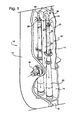
- a conventional reactor will include a reactor pressure vessel 10 that includes a reactor pressure vessel wall 12 and an inner core shroud 14 defining a generally annular space 16 therebetween that contains coolant.
- a plurality of jet pumps one being generally designated 18, are disposed at circumferential spaced positions surrounding the pressure vessel in the annular space 16 defined between the pressure vessel wall 12 and the core shroud 14.
- Each jet pump 18 typically comprises an inlet riser 20, a transition piece 28 adjacent the upper end of the inlet riser 20, a pair of elbows 22, inlet-mixers 23, each including nozzles 24 and mixing sections 25, and diffusers 26.
- Hold down assemblies adjacent the top of the jet pump 18, together with a number of braces and restraining assemblies maintain each jet pump 18 in a substantially fixed position in the annular space 16 between the core shroud 14 and pressure vessel wall 12.
- a thermal sleeve 32 penetrates the pressure vessel wall 12 and is welded at its juncture with an inlet elbow with the opposite end of the inlet elbow being secured to the lower end of the inlet riser 20.
- coolant enters the thermal sleeve 32 and flows through the elbow, upwardly in the inlet riser 20, through the inlet elbows 22 through nozzles 24 for flow in a downward direction through the mixing sections 25, the diffusers 26 and into a plenum 40 for upward flow through the reactor core.
- the jet pump nozzles 24 will induce a suction flow of coolant from the annular space 16 into the mixing section 25 which mixes with the coolant flow through the jet pump nozzles 23.
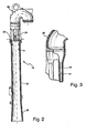
- FIG. 2 Illustrated more particularly to FIG. 2 is a portion of a jet pump 18 having an inlet elbow 22 adjacent five nozzles 24.
- the nozzles 24 are supported above the mixing sections 25 and, in combination with the mixing sections define a generally annular suction flow passage 29 between the nozzles 24 and an inlet to the mixing section 25.
- the mixing section 25 is typically a generally cylindrical pipe which terminates at its lower end in an inlet to the diffuser 26. Consequently, the flow of coolant through the nozzles 24 induces a suction flow of coolant through the annular spacer 16 for flow into the mixing section 25.
- These combined nozzle and suction flows pass through the mixing section 25 and diffuser 26 and into plenum 40.
- FIG. 3 Illustrated in FIG. 3 are two of the nozzles 24. It will be appreciated that the interior passages through nozzles 24 are generally conical or frusto-conical in shape with the diameter decreasing along the path of the fluid flow, thereby increasing the flow velocity into mixing section 25. The increased velocity induces additional fluid to flow into the sleeve through the annular opening 29 between the nozzles 23 and the mixer sleeve inlet as indicated by the arrows in FIG. 2 .
- the inlet-mixer is provided with a coating that inhibits or eliminates "crud” build-up.
- the inlet-mixer 23 is placed in a chemical vapor deposition ("CVD") reactor.
- the reactor is a heated vacuum vessel that is sufficiently large to house the part being coated.
- the vessel is then evacuated and the pressure is dropped to approximately 2670 Pa (20 mTorr).
- Heat is applied to raise the temperature of the vessel and the part being coated to a reaction temperature sufficient to decompose an organometallic source gas, typically within a range of about 400°-500° C. and preferably about 450° C.
- chemical precursors such as one or more organometallic precursor or source gases are injected into the reactor chamber.
- the precursor gas(es) impinge on the surface of the heated inlet-mixer part and thermally decompose to form a metal oxide insulator coating corresponding to the metallic portion of the source gas(es) and byproduct gases.
- source gases such as Ti(OC 2 H 5 ) 4 and Ta(OC 2 H 5 ) 5 are useful for forming the corresponding oxides TiO 2 and Ta 2 O 5 .
- this method may be used to deposit layers including such metallic oxides as TiO 2 , Ta 2 O 5 , SiO 2 , Al 2 O 3 , ZrO 2 , Nb 2 O 5 , SrBi 2 , Ta 2 O 3 , Y 2 O 3 , HfO 2 , BaO, SrO, SrTiO 3 , PbTiO 3 , and PbZrO 3 , and byproduct gases that are evacuated from the reactor vessel.
- the deposition process is maintained for a period sufficient to achieve a base metal oxide coating of the desired thickness, typically between about 0.1 and 2 ⁇ m, after which the gas flow of the first precursor gas(es) is terminated.
- the reactor vessel may then be purged with an inert gas or gases to remove the initial precursor gas(es) while generally maintaining the reactor pressure and temperature.
- an inert gas or gases to remove the initial precursor gas(es) while generally maintaining the reactor pressure and temperature.
- a different organometallic precursor or source gas or mixture of such gases is introduced into the reactor chamber.
- the precursor gas(es) impinge on the surface of the first metal oxide insulator layer formed on the heated inlet-mixer part and thermally decompose to form a second metal oxide insulator coating corresponding to the metallic portion of the source gas(es) and byproduct gases.
- heating is terminated and the reactor vessel and the coated part are cooled. Once the temperature is sufficiently low, the vacuum is released and the reactor chamber opened to allow removal of the coated jet pump part removed.
- the coating is indicated 31 in FIGS. 2 and 3 along the interior wall surfaces of the inlet-mixer 23.
- the multi-layer coating process for the high flow surfaces of the jet pump provides for the application of an initial or base dielectric coating of relatively smaller thickness (e.g., about 0.1 to about 0.5 ⁇ m) which exhibits improved adherence to the base material and provides a clean surface for the application of the second or outer dielectric coating.
- the second or outer dielectric coating may then be selected to provide sufficient adherence to the initial or base dielectric coating while providing improved resistance to the anticipated operating environment.
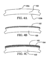
- a part 100 fabricated from a conductive material and having a wetted surface is initially coated with a base dielectric layer 102, after which a second and different dielectric layer 104 is applied to the base dielectric layer.
- Suggested initial coating materials include the oxide material tantala (Ta 2 O 5 ) with the outer coat being titania (TiO 2 ).
- TiO 2 titania
- a wide range of metal oxide dielectrics may be used to form the base and outer coatings, including, for example, zirconia, silica, alumina, or other metal oxide that exhibits sufficient resistance to anticipated operating environment.
- the CVD process as described above, or another gas phase deposition process such as Atomic Layer Deposition (ALD) are generally suitable for forming a conformal surface coating on a complex three-dimensional surface.
- PVD physical vapor deposition
- PEPVD plasma enhanced physical vapor deposition
- RF radio frequency
- EAS electric arc spraying
- PAS plasma spray coating processes
- APS atmospheric pressure
- VPS vacuum
- LPPS low pressure inert gas
- HVOF high velocity oxy-fuel
- the initial dielectric coating such as Ta 2 O 5
- the outer coating such as TiO 2
- This same dual-coat approach may be applied to replacement components such as core spray piping to improve resistance to stress corrosion cracking.
- Other parts that could benefit from a dielectric coating include impellers, flow elements, valves, other application which are exposed to high flow water and susceptible to fouling from the charged ions in the fluid.
- Ta 2 O 5 will be suitable for forming an initial coating that will provide both sufficient electrical resistance and sufficient adhesion on a range of base metals, such as stainless steel, used in fabricating the parts. It is also anticipated that TiO 2 will be suitable for forming an outer layer on a Ta 2 O 5 base coating that will exhibit both sufficient adherence to the underlying Ta 2 O 5 layer while improving the corrosion resistance in a BWR environment over that exhibited by Ta 2 O 5 . It is anticipated that the multi-layer Ta 2 O 5 /TiO 2 dielectric coating will outperform a single dielectric coat of Ta 2 O 5 or TiO 2 having the same thickness in BWR applications, including jet pump surfaces.
- the coating process as described above may incorporate additional steps such as a cleaning or etching step to prepare the surface of the part being coated to receive the base dielectric coating and improve the adhesion of the base layer.
- additional steps such as a cleaning or etching step to prepare the surface of the part being coated to receive the base dielectric coating and improve the adhesion of the base layer.
- additional surface treatments such as nitridation or other surface modification processes may be utilized to increase the resistance of the outer layer to the anticipated operating environment for the coated part.
Landscapes
- Chemical & Material Sciences (AREA)
- Engineering & Computer Science (AREA)
- Mechanical Engineering (AREA)
- Organic Chemistry (AREA)
- Metallurgy (AREA)
- Chemical Kinetics & Catalysis (AREA)
- Materials Engineering (AREA)
- Physics & Mathematics (AREA)
- Inorganic Chemistry (AREA)
- High Energy & Nuclear Physics (AREA)
- General Engineering & Computer Science (AREA)
- Plasma & Fusion (AREA)
- General Chemical & Material Sciences (AREA)
- Ceramic Engineering (AREA)
- Physical Or Chemical Processes And Apparatus (AREA)
- Chemical Vapour Deposition (AREA)
- Other Surface Treatments For Metallic Materials (AREA)
- Laminated Bodies (AREA)
Description
- The present invention relates to apparatus and methods for eliminating or substantially inhibiting electrostatic deposition of charged particles from the coolant onto the surface of an inlet-mixer of a jet pump forming part of a water recirculation system in a boiling water nuclear reactor, and for inhibiting stress corrosion cracking of the metallic parts. This invention particularly relates to an insulating barrier coating that eliminates or substantially inhibits the interaction between the conductive metal housing of the inlet-mixer of the jet pump assembly and the ionic particles in the fluid.
- In a boiling water nuclear reactor, an annular space is defined between the core shroud and the reactor pressure vessel wall. Jet pumps are located in the annular space for recirculating coolant through the reactor. The recirculation system circulates the cooling medium around the nuclear reactor core. Jet pumps, which contain no moving parts, provide an internal circulation path for the core coolant flow. Typically, a substantial number of jet pumps, for example, on the order of sixteen to twenty-four, are installed in this annular space. Each jet pump assembly consists of a riser assembly, a riser brace, two inlet-mixer assemblies, and two diffuser assemblies. The inlet-mixer includes a nozzle and a suction inlet. The nozzle may have one orifice or five orifices, depending on the jet pump design. The top of the inlet-mixer is mechanically clamped to the top of the riser transition piece, while the exit end of the inlet-mixer fits into a slip joint with the top of the diffuser. The inlet-mixer is a removable component.
- A recirculation pump, external to the reactor vessel, pulls suction from the downward flow of coolant in the annular space. The coolant is pumped to a higher pressure, and is distributed through a manifold to the jet pumps, where the coolant flows in an upward direction through the risers. The coolant splits in the transition piece and changes direction. It is then accelerated in a downward direction through the nozzles and into a mixer section of the jet pump. The nozzles cause a high velocity coolant flow that is approximately one third of the core flow and discharges into the inlet-mixers. Momentum causes surrounding water in the downcomer region of the annulus to also enter the mixer section where it mixes with the outflow from the nozzles for flow through the mixer section and diffuser. This combined flow discharges into the lower core plenum. The coolant then flows upward between the control rod drive guide tubes and is distributed for flow along individual fuel rods inside the fuel channels.
- Over time, contaminants tend to accumulate on the inside surface of the inlet-mixers including the jet pump nozzles, forming a layer of "crud." There is also potential for stress corrosion cracking along these surfaces. The build-up of "crud" is attributed, at least in part, to charged particles suspended in the coolant which interact with the metallic inner surface of the inlet-mixer inducing a triboelectrostatic charge on the surface. This charge creates an electrostatic potential that attracts the suspended particles in the fluid to the metallic surface where they form a layer of particle contaminants. The greatest deposition of "crud" tends to be observed in areas that experience a high velocity flow rate.
- The accumulation of the layer of "crud" will tend to degrade the performance of the recirculation system. If the accumulation is excessive, this degradation will affect the efficiency of the plant because the recirculation pumps must be run at a higher speed to maintain core flow. Degradation of jet pump performance can also result in extreme jet pump vibration and damage to jet pump components. Eventually, the inlet-mixer must be mechanically cleaned or replaced during regular maintenance and refueling outages. This process is expensive and time consuming. Consequently, it is important that the accumulation of this layer of "crud" be suppressed or substantially eliminated in order to preserve a clear flow path and maintain the performance of the recirculation system.
- In the past, cleaning processes have been proposed that remove the "crud" layer from the inside surface of the inlet-mixer. These processes require removal of the inlet-mixer from the reactor for cleaning in the fuel pool. This is typically accomplished at regular scheduled shutdowns of the reactor, at which times the necessary maintenance is performed. A process using an electrical circuit has also been proposed for reducing the electrostatic deposition of charged particles on the inlet-mixer surfaces that are exposed to the free stream electrical potential in
U.S. Pat. No. 5,444,747 . This process employs a DC circuit with an active element feedback loop that adjusts the surface potential of the inlet-mixer to minimize the net flux to the inner conducting surface of the parts and thereby reduces particulate deposition. Implementation of this process, however, requires significant attention and maintenance and adds to the overall complexity of the recirculation system. -
EP-A-1 211 695 discloses a jet pump for a nuclear reactor in which, to minimize or eliminate electrostatic deposition of charged particulates carried by the coolant on interior wall surface of the inlet-mixer of the jet pump, and also to inhibit stress corrosion cracking, the interior wall surfaces of the nozzles and mixing section are coated with a ceramic oxide such as SiO2 and Ta2O5 to thicknesses of about 0.5-1.5 microns. - There remains, however, a need for an improved apparatus and methods of protecting the inlet-mixers of the jet pumps from contaminant build-up. Furthermore, there remains a need for an improved solution to the problem of "crud" build-up which gradually degrades their performance and requires the need for periodically cleaning and maintaining the jet pump.
- The present invention provides a method for forming a multi-layer dielectric coating for reducing or eliminating deposition of charged particulates on the wetted surfaces of the flow passages of a jet pump in a boiling water reactor. In particular, to reduce the electrostatic potential between the ionic fluid flow and such surfaces and thereby suppress or eliminate the build-up of crud, a coating is provided on the inlet-mixer surfaces. By reducing the electrostatic potential, the coating inhibits or reduces the formation of a particulate layer on the coated surfaces. Furthermore, the insulative coating tends to reduce the susceptibility of the coated inlet-mixer surfaces to stress corrosion cracking by lowering the electrochemical corrosion potential (ECP).
- To achieve the desired improvements, the interior surfaces of the inlet-mixers are provided with a coating which reduces or eliminates the build-up of charged particles on those surfaces. Particularly, the interior surfaces of each inlet-mixer are coated with a dielectric material that will tend to insulate the surfaces of these parts electrically from the fluid flow. This insulating layer will tend to suppress the development of an electrostatic potential typically resulting from triboelectrostatic charge induced on the conductive inner surfaces of the inlet-mixer. By suppressing the development of an electrostatic potential, the insulating layer will suppress the potential for interaction between the surface and charged particles suspended in the water.
- Thus, the coating tends to suppress or eliminate electrochemical interaction between the conductive housing surfaces and the ionic particles in the coolant. Because the charged particles are not attracted to the dielectric-coated surface to the degree that they are attracted to an uncoated conductive surface, the potential crud-forming or contaminating particles tend to pass through the inlet-mixer without being deposited on the interior surfaces of the inlet-mixer. The dielectric coating, therefore, reduces or eliminates the need for costly cleaning and maintenance of the jet pump and maintains the flow path clear of these potential contaminants.
- The dielectric coating electrochemically isolates the conductive surfaces from the reactor water and tends to retard diffusion of oxygen from the reactor water to the metal surfaces. These effects tend to reduce susceptibility to stress corrosion cracking of the metallic parts.
- The main purpose of this disclosure is to increase the performance and lifetime of the dielectric coating applied to components used in light water reactors such as Boiling Water Reactors (BWR), Pressurized Water Reactors (PWR), CANDU reactors, etc., such as jet pump nozzles/inlet mixers to reduce the oxide fouling on high flow surfaces. It is proposed to apply a dual coat; first to apply a thin layer of Ta2O5, followed by another layer of TiO2. This novel treatment will allow for a more electrically resistant coat in addition to a more adherent coat. For example, it has been shown that a Ta2O5 coating provides an excellent adherence to various substrates. In addition, the TiO2 layer will have a greater adherence to the Ta2O5 layer compared to its adherence to the base material of interest.
- This dual-coat approach may be applied to replacement components such as core spray piping to improve resistance to stress corrosion cracking and other forms of corrosion, such as erosion corrosion. As used herein, erosion corrosion refers to corrosion of a metal that is caused or accelerated by the relative motion of the environment and the metal surface and is typically characterized by surface features with a directional pattern which are a direct result of the flowing media. Other factors such as turbulence, cavitation, impingement or galvanic effects can add to the severity of the corrosion. Other potential applications are impellers, flow elements, valves, other applications which are exposed to high flow water and are susceptible to fouling from the charged ions in the fluid.
- The coating is an insulating metal oxide coating, e.g., a coating formed of TiO2 or Ta2O5. The coating is applied by placing the part, such as a nozzle assembly, in a heated vacuum reactor vessel. Once the desired reaction conditions have been achieved, one or more suitable chemical precursors, e.g., Ti(OC2H5)4 or Ta(OC2H5)5, are introduced into the system. These precursor compounds thermally decompose on the surface of the part being processed, producing the dielectric coating and releasing several byproduct gases. The product is then cooled and ready for installation in the nuclear reactor.
- In a first exemplary embodiment according to the present invention, there is provided a method for reducing deposition of charged particulates on a conductive surface defining a wetted portion of a coolant flow passage in a nuclear reactor, comprising the steps of preparing the conductive surface and forming a base dielectric layer by exposing the conductive surface to a first organometallic precursor compound under conditions sufficient to decompose the precursor compound and form a substantially continuous base dielectric layer on the conductive surface. The method further comprises forming an outer dielectric layer by exposing the conductive surface to a second organometallic precursor compound different from said first organometallic precursor compound under conditions sufficient to decompose the precursor compound and form a substantially continuous outer dielectric layer on the base dielectric layer, said outer dielectric layer being different from said base dielectric layer. The step of forming a base dielectric layer comprises maintaining the conductive surface at a first deposition temperature of between about 400° C. and about 500° C. and a first deposition pressure of no more than about 2.67 Pa (20 mTorr). The step of forming the outer dielectric layer comprises maintaining the base dielectric layer at a second deposition temperature of between about 400° C. and about 500° C. and a second deposition pressure of no more than about 2.67 Pa (20 mTorr). The base dielectric layer consists essentially of Ta2O5, and has a base layer thickness of between about 0.1 and about 2 µm. The outer dielectric layer consists essentially of TiO2, and has an outer layer thickness of between about 0.5 µm and about 3 µm.
- In a second exemplary embodiment according to the present invention, there is provided an inlet mixer of a jet pump for apparatus defining a coolant flow passage in a nuclear reactor comprising a base material, the base material being electrically conductive and having a surface configured to define a portion of a coolant flow passage, and a base dielectric layer formed on the surface, the base dielectric layer being substantially continuous. The apparatus further comprises an outer dielectric layer formed on the base dielectric layer, the outer dielectric layer being different from the base dielectric layer; and being substantially continuous, wherein the outer dielectric layer defines a wetted surface in the coolant flow passage. The base dielectric layer consists essentially of Ta2O5 and has a base layer thickness of between about 0.1 and about 2 µm. The outer dielectric layer consists essentially of TiO2, and has an outer layer thickness of between about 0.5 µm and about 3 µm.
- In a particular application, a multi-layer dielectric coating is provided to reduce or eliminate deposition of charged particulates on the wetted surfaces of the flow passages of a jet pump in a boiling water reactor.
- Embodiments of the invention will now be described, by way of example, with reference to the accompanying drawings, in which:
-
FIG. 1 is a fragmentary perspective view with portions broken out of a jet pump in an annular space between the inner shroud and the pressure vessel wall of a nuclear reactor; -
FIG. 2 is an enlarged elevation view of a transition piece adjacent the top of the pump, an inlet-mixer, and a diffuser with parts in cross-section for ease of illustration; -
FIG. 3 is an enlarged fragmentary cross-sectional view of a nozzle discharge port of the inlet-mixer; and -
FIGS. 4A-4C are cross-sectional views of a portion of a coated surface during the coating process. - These drawings have been provided to assist in the understanding of the exemplary embodiments of the invention as described in more detail below. The relative spacing, positioning, sizing and dimensions of the various elements illustrated in the drawings are not drawn to scale and may have been exaggerated, reduced or otherwise modified for the purpose of improved clarity.
- As illustrated in
FIG. 1 , a conventional reactor will include areactor pressure vessel 10 that includes a reactorpressure vessel wall 12 and aninner core shroud 14 defining a generallyannular space 16 therebetween that contains coolant. As in a typical BWR, a plurality of jet pumps, one being generally designated 18, are disposed at circumferential spaced positions surrounding the pressure vessel in theannular space 16 defined between thepressure vessel wall 12 and thecore shroud 14. Eachjet pump 18 typically comprises an inlet riser 20, atransition piece 28 adjacent the upper end of the inlet riser 20, a pair ofelbows 22, inlet-mixers 23, each includingnozzles 24 and mixingsections 25, anddiffusers 26. Hold down assemblies adjacent the top of thejet pump 18, together with a number of braces and restraining assemblies maintain eachjet pump 18 in a substantially fixed position in theannular space 16 between thecore shroud 14 andpressure vessel wall 12. Athermal sleeve 32 penetrates thepressure vessel wall 12 and is welded at its juncture with an inlet elbow with the opposite end of the inlet elbow being secured to the lower end of the inlet riser 20. - It will be appreciated that the foregoing-described
jet pump 18 is conventional in construction. Thus, coolant enters thethermal sleeve 32 and flows through the elbow, upwardly in the inlet riser 20, through theinlet elbows 22 throughnozzles 24 for flow in a downward direction through the mixingsections 25, thediffusers 26 and into aplenum 40 for upward flow through the reactor core. During conventional operation, thejet pump nozzles 24 will induce a suction flow of coolant from theannular space 16 into the mixingsection 25 which mixes with the coolant flow through thejet pump nozzles 23. - Illustrated more particularly to
FIG. 2 is a portion of ajet pump 18 having aninlet elbow 22 adjacent fivenozzles 24. Thenozzles 24 are supported above the mixingsections 25 and, in combination with the mixing sections define a generally annularsuction flow passage 29 between thenozzles 24 and an inlet to themixing section 25. It will be appreciated that the mixingsection 25 is typically a generally cylindrical pipe which terminates at its lower end in an inlet to thediffuser 26. Consequently, the flow of coolant through thenozzles 24 induces a suction flow of coolant through theannular spacer 16 for flow into the mixingsection 25. These combined nozzle and suction flows pass through the mixingsection 25 anddiffuser 26 and intoplenum 40. - Illustrated in
FIG. 3 are two of thenozzles 24. It will be appreciated that the interior passages throughnozzles 24 are generally conical or frusto-conical in shape with the diameter decreasing along the path of the fluid flow, thereby increasing the flow velocity into mixingsection 25. The increased velocity induces additional fluid to flow into the sleeve through theannular opening 29 between thenozzles 23 and the mixer sleeve inlet as indicated by the arrows inFIG. 2 . - In accordance with a preferred embodiment of the present invention, the inlet-mixer is provided with a coating that inhibits or eliminates "crud" build-up. To accomplish this, the inlet-
mixer 23 is placed in a chemical vapor deposition ("CVD") reactor. The reactor is a heated vacuum vessel that is sufficiently large to house the part being coated. The vessel is then evacuated and the pressure is dropped to approximately 2670 Pa (20 mTorr). Heat is applied to raise the temperature of the vessel and the part being coated to a reaction temperature sufficient to decompose an organometallic source gas, typically within a range of about 400°-500° C. and preferably about 450° C. - When the reactor vessel reaches the reaction temperature and pressure, chemical precursors, such as one or more organometallic precursor or source gases are injected into the reactor chamber. The precursor gas(es) impinge on the surface of the heated inlet-mixer part and thermally decompose to form a metal oxide insulator coating corresponding to the metallic portion of the source gas(es) and byproduct gases. For example, source gases such as Ti(OC2H5)4 and Ta(OC2H5)5 are useful for forming the corresponding oxides TiO2 and Ta2O5. Depending on the selection of the precursor gas(es), this method may be used to deposit layers including such metallic oxides as TiO2, Ta2O5, SiO2, Al2O3, ZrO2, Nb2O5, SrBi2, Ta2O3, Y2O3, HfO2, BaO, SrO, SrTiO3, PbTiO3, and PbZrO3, and byproduct gases that are evacuated from the reactor vessel. The deposition process is maintained for a period sufficient to achieve a base metal oxide coating of the desired thickness, typically between about 0.1 and 2 µm, after which the gas flow of the first precursor gas(es) is terminated.
- The reactor vessel may then be purged with an inert gas or gases to remove the initial precursor gas(es) while generally maintaining the reactor pressure and temperature. After the majority of the initial precursor gas(es) have been removed from the reactor, a different organometallic precursor or source gas or mixture of such gases is introduced into the reactor chamber. The precursor gas(es) impinge on the surface of the first metal oxide insulator layer formed on the heated inlet-mixer part and thermally decompose to form a second metal oxide insulator coating corresponding to the metallic portion of the source gas(es) and byproduct gases.
- When a sufficiently thick coating is achieved, e.g., within a range of about 0.5 to about 3.0 µm, heating is terminated and the reactor vessel and the coated part are cooled. Once the temperature is sufficiently low, the vacuum is released and the reactor chamber opened to allow removal of the coated jet pump part removed. The coating is indicated 31 in
FIGS. 2 and 3 along the interior wall surfaces of the inlet-mixer 23. - The multi-layer coating process for the high flow surfaces of the jet pump provides for the application of an initial or base dielectric coating of relatively smaller thickness (e.g., about 0.1 to about 0.5 µm) which exhibits improved adherence to the base material and provides a clean surface for the application of the second or outer dielectric coating. The second or outer dielectric coating may then be selected to provide sufficient adherence to the initial or base dielectric coating while providing improved resistance to the anticipated operating environment. As illustrated in
FIGS. 4A-4C , apart 100 fabricated from a conductive material and having a wetted surface is initially coated with abase dielectric layer 102, after which a second and differentdielectric layer 104 is applied to the base dielectric layer. - Suggested initial coating materials include the oxide material tantala (Ta2O5) with the outer coat being titania (TiO2). As noted above, a wide range of metal oxide dielectrics may be used to form the base and outer coatings, including, for example, zirconia, silica, alumina, or other metal oxide that exhibits sufficient resistance to anticipated operating environment. The CVD process as described above, or another gas phase deposition process such as Atomic Layer Deposition (ALD), are generally suitable for forming a conformal surface coating on a complex three-dimensional surface. Depending on the size and configuration of the surface(s) being coated, physical vapor deposition (PVD), plasma enhanced physical vapor deposition (PEPVD) and radio frequency (RF) sputtering may also be suitable.
- Similarly, depending on the configuration of the part and the surface to be coated, other methods of applying protective material layer could also be utilized to form the base coating and/or the outer coating. These methods may include electric arc spraying (EAS), plasma spray coating processes, also referred to as plasma arc spraying (PAS) processes, which can be conducted at atmospheric pressure (APS), under a vacuum (VPS), or in the presence of a low pressure inert gas (LPPS), high velocity oxy-fuel (HVOF) processes and/or other conventional coating processes that are capable of producing the appropriate dielectric layers of sufficient thickness and uniformity.
- The initial dielectric coating, such as Ta2O5, allows for increased electrical resistance against fouling and adherence of the outer coating to the part, thereby suppressing delamination. The outer coating, such as TiO2, may then be selected to provide improved resistance to the jet pump environment while exhibiting good adherence to the initial or intermediate coatings and to reduce or eliminate surface fouling. This same dual-coat approach may be applied to replacement components such as core spray piping to improve resistance to stress corrosion cracking. Other parts that could benefit from a dielectric coating include impellers, flow elements, valves, other application which are exposed to high flow water and susceptible to fouling from the charged ions in the fluid.
- It is anticipated that Ta2O5 will be suitable for forming an initial coating that will provide both sufficient electrical resistance and sufficient adhesion on a range of base metals, such as stainless steel, used in fabricating the parts. It is also anticipated that TiO2 will be suitable for forming an outer layer on a Ta2O5 base coating that will exhibit both sufficient adherence to the underlying Ta2O5 layer while improving the corrosion resistance in a BWR environment over that exhibited by Ta2O5. It is anticipated that the multi-layer Ta2O5/TiO2 dielectric coating will outperform a single dielectric coat of Ta2O5 or TiO2 having the same thickness in BWR applications, including jet pump surfaces.
- It will be appreciated by those of ordinary skill in the art that the coating process as described above may incorporate additional steps such as a cleaning or etching step to prepare the surface of the part being coated to receive the base dielectric coating and improve the adhesion of the base layer. Similarly, although the process as generally been described as a dual layer process, it will be appreciated that one or more intermediate layers may be provided to allow for more precise control of the characteristics of the coating. In addition, additional surface treatments such as nitridation or other surface modification processes may be utilized to increase the resistance of the outer layer to the anticipated operating environment for the coated part.
Claims (5)
- A method for reducing deposition of charged particulates on a conductive surface (100a, 100b) defining a wetted portion of a coolant flow passage in a nuclear reactor, comprising the steps of:preparing the conductive surface;forming a base dielectric layer (102) by exposing the conductive surface to a first organometallic precursor compound under conditions sufficient to decompose the precursor compound and form a substantially continuous base dielectric layer on the conductive surface;characterized by:forming an outer dielectric layer (104) by exposing the conductive surface to a second organometallic precursor compound different from said first organometallic precursor compound under conditions sufficient to decompose the precursor compound and form a substantially continuous outer dielectric layer on the base dielectric layer, said outer dielectric layer being different from said base dielectric layer; whereinforming a base dielectric layer comprises maintaining the conductive surface at a first deposition temperature of between 400°C and 500° C. and a first deposition pressure of no more than about 2.67 Pa (20 mTorr); andforming the outer dielectric layer (104) comprises maintaining the base dielectric layer at a second deposition temperature of between 400° C. and 500° C. and a second deposition pressure of no more than about 2.67 Pa (20 mTorr); and whereinthe base dielectric layer (102) consists essentially of Ta2O5 and has a base layer thickness of between 0.1 and 2µm; andthe outer dielectric layer (102) consists essentially of TiO2 and has an outer layer thickness of between 0.5 µm and 3 µm.
- A method according to claim 1, further comprising:forming the base dielectric layer (102) using a method selected from a group consisting of atomic layer deposition (ALD), chemical vapor deposition (CVD), physical vapor deposition (PVD), plasma enhanced physical vapor deposition (PEPVD), sputtering, plasma spray coating (APS, VPS and LPPS) and high velocity oxy-fuel (HVOF) processes; andforming the outer dielectric layer (104) using a method selected from a group consisting of atomic layer deposition (ALD), chemical vapor deposition (CVD), physical vapor deposition (PVD), plasma enhanced physical vapor deposition (PEPVD), sputtering, electric arc spraying (EAS), plasma spray coating (APS, VPS and LPPS) and high velocity oxy-fuel (HVOF) processes.
- A method according to claims 1 or 2, further comprising:forming the base dielectric layer (102) and the outer dielectric layer (104) utilizing a CVD process.
- A method according to claims 1 or 2, further comprising:forming the base dielectric layer (102) utilizing an ALD process and the outer dielectric layer (104) utilizing a CVD process.
- An inlet mixer of a jet pump for a nuclear reactor, the inlet mixer having a coolant flow passage comprising:a base material (100), the base material being electrically conductive and having a surface (100a, 100b) configured to define a portion of a coolant flow passage;a base dielectric layer (102) formed on the surface, the base dielectric layer being substantially continuous;characterized by:an outer dielectric layer (104) formed on the base dielectric layer, the outer dielectric layer being different from the base dielectric layer; and being substantially continuous, wherein the outer dielectric layer defines a wetted surface in the coolant flow passage; and whereinthe base dielectric layer (102) consists essentially of Ta2O5 and has a base layer thickness of between 0.1 and 2 µm; andthe outer dielectric layer (102) consists essentially of TiO2 and has an outer layer thickness of between 0.5 µm and 3 µm.
Applications Claiming Priority (1)
| Application Number | Priority Date | Filing Date | Title |
|---|---|---|---|
| US11/024,952 US8023609B2 (en) | 2004-12-30 | 2004-12-30 | Dielectric coating for surfaces exposed to high temperature water |
Publications (3)
| Publication Number | Publication Date |
|---|---|
| EP1676936A2 EP1676936A2 (en) | 2006-07-05 |
| EP1676936A3 EP1676936A3 (en) | 2007-04-04 |
| EP1676936B1 true EP1676936B1 (en) | 2010-04-07 |
Family
ID=36084383
Family Applications (1)
| Application Number | Title | Priority Date | Filing Date |
|---|---|---|---|
| EP05257954A Expired - Lifetime EP1676936B1 (en) | 2004-12-30 | 2005-12-22 | Improved dielectric coating for surfaces exposed to high temperature water |
Country Status (7)
| Country | Link |
|---|---|
| US (2) | US8023609B2 (en) |
| EP (1) | EP1676936B1 (en) |
| JP (1) | JP4943701B2 (en) |
| DE (1) | DE602005020411D1 (en) |
| ES (1) | ES2341783T3 (en) |
| MX (1) | MXPA05013942A (en) |
| TW (1) | TWI372398B (en) |
Families Citing this family (12)
| Publication number | Priority date | Publication date | Assignee | Title |
|---|---|---|---|---|
| US20090046825A1 (en) * | 2007-08-16 | 2009-02-19 | Ge-Hitachi Nuclear Energy Americas Llc | Protective coating applied to metallic reactor components to reduce corrosion products into the nuclear reactor environment |
| WO2009025330A1 (en) * | 2007-08-23 | 2009-02-26 | Kabushiki Kaisha Toshiba | Method of inhibiting adhesion of radioactive substance and apparatus inhibited from suffering adhesion thereof |
| US8349408B2 (en) * | 2008-09-03 | 2013-01-08 | Ge-Hitachi Nuclear Energy Americas, Llc | Method of protecting reactor components from fouling |
| JP5513864B2 (en) * | 2008-12-12 | 2014-06-04 | 株式会社東芝 | Reactor internal structure and manufacturing method thereof |
| JP5361500B2 (en) * | 2009-04-03 | 2013-12-04 | 株式会社東芝 | Jet pump and vibration suppressing method thereof |
| KR101163999B1 (en) | 2010-02-19 | 2012-07-18 | 한국원자력연구원 | An underwater repairing method for damaged spots of water contacting surface and an apparatus for the method |
| JP4810617B1 (en) * | 2010-07-27 | 2011-11-09 | 株式会社東芝 | Plant corrosion control method and plant |
| WO2013191743A1 (en) * | 2012-02-17 | 2013-12-27 | The Massachusetts Institute Of Technology | Surface modification of cladding material |
| DE102012220559A1 (en) * | 2012-11-12 | 2014-05-15 | Siemens Aktiengesellschaft | Cooling for electric generators |
| US10847273B2 (en) | 2014-01-17 | 2020-11-24 | Ge-Hitachi Nuclear Energy Americas Llc | Steam separator and nuclear boiling water reactor including the same |
| WO2016179255A1 (en) * | 2015-05-04 | 2016-11-10 | Cerium Laboratories, Llc | Enhanced surface treatments |
| CN112562944A (en) * | 2020-12-11 | 2021-03-26 | 国网黑龙江省电力有限公司电力科学研究院 | Selective coating method suitable for hardware surface coating in strong wind and sand area |
Family Cites Families (20)
| Publication number | Priority date | Publication date | Assignee | Title |
|---|---|---|---|---|
| CA1064626A (en) * | 1977-06-09 | 1979-10-16 | Majesty (Her) In Right Of Canada As Represented By Atomic Energy Of Cana Da Limited | Deposit suppression in the core of water-cooled nuclear reactors |
| US4297150A (en) * | 1979-07-07 | 1981-10-27 | The British Petroleum Company Limited | Protective metal oxide films on metal or alloy substrate surfaces susceptible to coking, corrosion or catalytic activity |
| CA1232827A (en) * | 1984-04-20 | 1988-02-16 | Yasumasa Furutani | Inhibition of deposition of radioactive substances on nuclear power plant components |
| JPS63274751A (en) * | 1987-05-01 | 1988-11-11 | Toyota Motor Corp | Ceramic thermally sprayed member |
| DE69003479T2 (en) * | 1989-07-21 | 1994-01-20 | Cogema | Process for producing a chromium oxide protective layer between the tablets and the cooling tube of a nuclear fuel element and nuclear fuel element with such a protective layer. |
| US5147597A (en) * | 1991-04-09 | 1992-09-15 | Electric Power Research Institute | Prestabilized chromium protective film to reduce radiation buildup |
| US5510173A (en) * | 1993-08-20 | 1996-04-23 | Southwall Technologies Inc. | Multiple layer thin films with improved corrosion resistance |
| JPH07228963A (en) * | 1994-02-17 | 1995-08-29 | Nuclear Fuel Ind Ltd | Ejection hardening type nickel base alloy material for nuclear fuel |
| US5444747A (en) | 1994-05-09 | 1995-08-22 | General Electric Company | Jet pump electro-nozzle |
| JP3605969B2 (en) * | 1996-10-31 | 2004-12-22 | 石川島播磨重工業株式会社 | Method of producing titanium oxide film for corrosion protection and titanium oxide film for corrosion protection |
| US6214473B1 (en) * | 1998-05-13 | 2001-04-10 | Andrew Tye Hunt | Corrosion-resistant multilayer coatings |
| US6254341B1 (en) * | 1998-11-13 | 2001-07-03 | General Electric Company | Engine having resistance to particle deposits |
| JP4043647B2 (en) * | 1999-06-23 | 2008-02-06 | 株式会社東芝 | Reactor structure material and method for reducing corrosion of reactor structure material |
| JP4627830B2 (en) * | 1999-12-20 | 2011-02-09 | 株式会社フルヤ金属 | Reaction vessel for supercritical hydrolytic decomposition apparatus and method for producing reaction vessel |
| JP4334106B2 (en) * | 2000-03-31 | 2009-09-30 | 株式会社東芝 | Photocatalyst deposition method for nuclear reactor structural materials |
| US6633623B2 (en) * | 2000-11-29 | 2003-10-14 | General Electric Company | Apparatus and methods for protecting a jet pump nozzle assembly and inlet-mixer |
| US6630202B1 (en) * | 2002-09-30 | 2003-10-07 | General Electric Company | CVD treatment of hard friction coated steam line plug grips |
| JP4430372B2 (en) * | 2003-04-15 | 2010-03-10 | 株式会社神戸製鋼所 | Metal structure excellent in corrosion resistance, material for producing the metal structure, and method for producing the metal structure |
| US7666522B2 (en) * | 2003-12-03 | 2010-02-23 | IMDS, Inc. | Laser based metal deposition (LBMD) of implant structures |
| US7001672B2 (en) * | 2003-12-03 | 2006-02-21 | Medicine Lodge, Inc. | Laser based metal deposition of implant structures |
-
2004
- 2004-12-30 US US11/024,952 patent/US8023609B2/en not_active Expired - Fee Related
-
2005
- 2005-12-19 MX MXPA05013942A patent/MXPA05013942A/en active IP Right Grant
- 2005-12-21 TW TW094145566A patent/TWI372398B/en not_active IP Right Cessation
- 2005-12-22 ES ES05257954T patent/ES2341783T3/en not_active Expired - Lifetime
- 2005-12-22 DE DE602005020411T patent/DE602005020411D1/en not_active Expired - Lifetime
- 2005-12-22 EP EP05257954A patent/EP1676936B1/en not_active Expired - Lifetime
- 2005-12-26 JP JP2005371381A patent/JP4943701B2/en not_active Expired - Lifetime
-
2011
- 2011-09-16 US US13/234,578 patent/US8675806B2/en not_active Expired - Fee Related
Also Published As
| Publication number | Publication date |
|---|---|
| MXPA05013942A (en) | 2006-07-10 |
| JP2006194873A (en) | 2006-07-27 |
| ES2341783T3 (en) | 2010-06-28 |
| TW200634849A (en) | 2006-10-01 |
| US8675806B2 (en) | 2014-03-18 |
| US20050265512A1 (en) | 2005-12-01 |
| DE602005020411D1 (en) | 2010-05-20 |
| JP4943701B2 (en) | 2012-05-30 |
| EP1676936A2 (en) | 2006-07-05 |
| EP1676936A3 (en) | 2007-04-04 |
| US8023609B2 (en) | 2011-09-20 |
| US20140029712A1 (en) | 2014-01-30 |
| TWI372398B (en) | 2012-09-11 |
Similar Documents
| Publication | Publication Date | Title |
|---|---|---|
| US8675806B2 (en) | Dielectric coating for surfaces exposed to high temperature water | |
| EP1211695B1 (en) | Apparatus and methods for protecting a jet pump nozzle assembly and inlet-mixer | |
| US8349408B2 (en) | Method of protecting reactor components from fouling | |
| US5942334A (en) | Multilayer thermal barrier coating | |
| JP4331479B2 (en) | High toughness zirconia ceramic components and coatings in semiconductor processing equipment and methods of manufacturing the same | |
| KR100934048B1 (en) | Gas discharge member and plasma processing device | |
| US7648782B2 (en) | Ceramic coating member for semiconductor processing apparatus | |
| JP2008150702A (en) | Method for suppressing temperature gradient in substrate surface and turbine engine part | |
| EP1739685A1 (en) | Method for mitigating oxide fouling on structural components in light water reactors | |
| JP2006194873A5 (en) | ||
| US9850581B2 (en) | Reactor internal structure and method of manufacturing the same | |
| US20120315496A1 (en) | Method of forming an oxide coating that reduces accumulation of radioactive species on a metallic surface | |
| KR20060031136A (en) | Thermal spray coating film for vacuum plasma chamber and its manufacturing method | |
| CN118186361A (en) | Method for forming corrosion-resistant coating, plug rod and semiconductor component | |
| EP3685100B1 (en) | Burner with a slurry coating with high resistance to metal dusting | |
| KR20260074342A (en) | Semiconductor chamber components having advanced double-layer nickel-containing coatings | |
| KR20260035205A (en) | Semiconductor process chamber components with laser-glazed metal oxide intermediate layers | |
| JP2023075617A (en) | Coating coated member and coating method | |
| KR20060089362A (en) | Water treatment filter manufacturing method using aerosol deposition method, and water treatment filter obtained through | |
| JP2018017664A (en) | Reactor pressure vessel, reactor and reactor pressure vessel production method |
Legal Events
| Date | Code | Title | Description |
|---|---|---|---|
| PUAI | Public reference made under article 153(3) epc to a published international application that has entered the european phase |
Free format text: ORIGINAL CODE: 0009012 |
|
| AK | Designated contracting states |
Kind code of ref document: A2 Designated state(s): AT BE BG CH CY CZ DE DK EE ES FI FR GB GR HU IE IS IT LI LT LU LV MC NL PL PT RO SE SI SK TR |
|
| AX | Request for extension of the european patent |
Extension state: AL BA HR MK YU |
|
| PUAL | Search report despatched |
Free format text: ORIGINAL CODE: 0009013 |
|
| AK | Designated contracting states |
Kind code of ref document: A3 Designated state(s): AT BE BG CH CY CZ DE DK EE ES FI FR GB GR HU IE IS IT LI LT LU LV MC NL PL PT RO SE SI SK TR |
|
| AX | Request for extension of the european patent |
Extension state: AL BA HR MK YU |
|
| 17P | Request for examination filed |
Effective date: 20071004 |
|
| AKX | Designation fees paid |
Designated state(s): CH DE ES FI LI SE |
|
| 17Q | First examination report despatched |
Effective date: 20080103 |
|
| GRAP | Despatch of communication of intention to grant a patent |
Free format text: ORIGINAL CODE: EPIDOSNIGR1 |
|
| GRAS | Grant fee paid |
Free format text: ORIGINAL CODE: EPIDOSNIGR3 |
|
| GRAA | (expected) grant |
Free format text: ORIGINAL CODE: 0009210 |
|
| AK | Designated contracting states |
Kind code of ref document: B1 Designated state(s): CH DE ES FI LI SE |
|
| REG | Reference to a national code |
Ref country code: CH Ref legal event code: EP Ref country code: CH Ref legal event code: NV Representative=s name: SERVOPATENT GMBH |
|
| REF | Corresponds to: |
Ref document number: 602005020411 Country of ref document: DE Date of ref document: 20100520 Kind code of ref document: P |
|
| REG | Reference to a national code |
Ref country code: ES Ref legal event code: FG2A Ref document number: 2341783 Country of ref document: ES Kind code of ref document: T3 |
|
| REG | Reference to a national code |
Ref country code: SE Ref legal event code: TRGR |
|
| PLBE | No opposition filed within time limit |
Free format text: ORIGINAL CODE: 0009261 |
|
| STAA | Information on the status of an ep patent application or granted ep patent |
Free format text: STATUS: NO OPPOSITION FILED WITHIN TIME LIMIT |
|
| 26N | No opposition filed |
Effective date: 20110110 |
|
| REG | Reference to a national code |
Ref country code: CH Ref legal event code: PCAR Free format text: NEW ADDRESS: WANNERSTRASSE 9/1, 8045 ZUERICH (CH) |
|
| PGFP | Annual fee paid to national office [announced via postgrant information from national office to epo] |
Ref country code: SE Payment date: 20201124 Year of fee payment: 16 Ref country code: FI Payment date: 20201123 Year of fee payment: 16 Ref country code: DE Payment date: 20201119 Year of fee payment: 16 |
|
| REG | Reference to a national code |
Ref country code: DE Ref legal event code: R119 Ref document number: 602005020411 Country of ref document: DE |
|
| REG | Reference to a national code |
Ref country code: FI Ref legal event code: MAE |
|
| REG | Reference to a national code |
Ref country code: SE Ref legal event code: EUG |
|
| PG25 | Lapsed in a contracting state [announced via postgrant information from national office to epo] |
Ref country code: FI Free format text: LAPSE BECAUSE OF NON-PAYMENT OF DUE FEES Effective date: 20211222 |
|
| PG25 | Lapsed in a contracting state [announced via postgrant information from national office to epo] |
Ref country code: SE Free format text: LAPSE BECAUSE OF NON-PAYMENT OF DUE FEES Effective date: 20211223 Ref country code: DE Free format text: LAPSE BECAUSE OF NON-PAYMENT OF DUE FEES Effective date: 20220701 |
|
| REG | Reference to a national code |
Ref country code: ES Ref legal event code: PC2A Owner name: GE HITACHI NUCLEAR ENERGY AMERICAS LLC Effective date: 20240709 |
|
| PGFP | Annual fee paid to national office [announced via postgrant information from national office to epo] |
Ref country code: ES Payment date: 20250102 Year of fee payment: 20 |
|
| PGFP | Annual fee paid to national office [announced via postgrant information from national office to epo] |
Ref country code: CH Payment date: 20250101 Year of fee payment: 20 |
|
| REG | Reference to a national code |
Ref country code: CH Ref legal event code: H14 Free format text: ST27 STATUS EVENT CODE: U-0-0-H10-H14 (AS PROVIDED BY THE NATIONAL OFFICE) Effective date: 20251222 |
|
| REG | Reference to a national code |
Ref country code: ES Ref legal event code: FD2A Effective date: 20260102 |
|
| PG25 | Lapsed in a contracting state [announced via postgrant information from national office to epo] |
Ref country code: ES Free format text: LAPSE BECAUSE OF EXPIRATION OF PROTECTION Effective date: 20251223 |