EP1676802A1 - Method and apparatus for folding sheets of paper - Google Patents
Method and apparatus for folding sheets of paper Download PDFInfo
- Publication number
- EP1676802A1 EP1676802A1 EP05078027A EP05078027A EP1676802A1 EP 1676802 A1 EP1676802 A1 EP 1676802A1 EP 05078027 A EP05078027 A EP 05078027A EP 05078027 A EP05078027 A EP 05078027A EP 1676802 A1 EP1676802 A1 EP 1676802A1
- Authority
- EP
- European Patent Office
- Prior art keywords
- folding
- sheet
- rollers
- nip
- folding rollers
- Prior art date
- Legal status (The legal status is an assumption and is not a legal conclusion. Google has not performed a legal analysis and makes no representation as to the accuracy of the status listed.)
- Granted
Links
Images

Classifications
-
- B—PERFORMING OPERATIONS; TRANSPORTING
- B65—CONVEYING; PACKING; STORING; HANDLING THIN OR FILAMENTARY MATERIAL
- B65H—HANDLING THIN OR FILAMENTARY MATERIAL, e.g. SHEETS, WEBS, CABLES
- B65H45/00—Folding thin material
- B65H45/12—Folding articles or webs with application of pressure to define or form crease lines
- B65H45/14—Buckling folders
-
- B—PERFORMING OPERATIONS; TRANSPORTING
- B65—CONVEYING; PACKING; STORING; HANDLING THIN OR FILAMENTARY MATERIAL
- B65H—HANDLING THIN OR FILAMENTARY MATERIAL, e.g. SHEETS, WEBS, CABLES
- B65H45/00—Folding thin material
- B65H45/12—Folding articles or webs with application of pressure to define or form crease lines
- B65H45/18—Oscillating or reciprocating blade folders
Definitions
- the invention relates to a method for folding sheets of paper according to the introductory portion of claim 1, and to an apparatus for folding sheets of paper according to the introductory portion of claim 7.
- Such a method and apparatus are known from U.S. Patent 5,490,829.
- a sheet to be folded is supplied via a nip between a pair of transport rollers and through a gap between a pair of pivotally suspended guides.
- the folding rollers are stopped and the guides are pivoted while the transport rollers supply the paper over some further distance. This causes the sheet to buckle and results in a loop in the sheet.
- the guides are swung back, whereby transport rollers arranged on the guides clamp the sheet against the one of the folding rollers that is situated on the side of the folding gap where also the loop has been formed and where the guides had been swung to.
- a bend in the sheet is urged between the folding rollers, whereby a first fold is formed.
- the loop together with the rest of the sheet also passes through the folding gap, in which the trailing end of the loop is pressed flat, so that a second fold is formed.
- two folds are formed.
- supplying the sheet is done by suitably driving the folding rollers, supplying the sheet does not require any separate set of transport rollers with associated drive.
- An additional advantage is that the sheets after folding are outputted on the side of the folding nip from where they have been supplied. This makes it simpler to realize a machine lay-out whereby input and output are situated on the same side of the machine, so that the user can perform both operations on the same side of the machine.
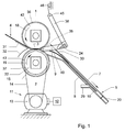
- the apparatus for folding a sheet of paper according to the example represented in the drawing is equipped with a pair of folding rollers 1, 2 which define a folding nip 3 situated between them.
- a transport path is provided, which, according to this example, is formed by guides 7, 8 jointly forming a buckle chute 5.
- the folding rollers 1, 2 extend throughout the width of the sheet 4, so that they can form a fold which extends throughout the width of the sheet 4.
- folding rollers typically differ from transport rollers which are typically narrower than the greatest dimension transverse to the direction of transport of the sheets to be transported.
- a first section 9 of the sheet, measured along the sheet 4, is situated closer to the folding nip 3 than a second section 10.
- the apparatus is equipped with a drive 11 and a control 12.
- the drive according to this example is made up of a motor 13, a drive belt 14, a pulley 15 which is connected with the folding roller 2 for driving rotation thereof and a clutch 16 which connects the folding rollers with the motor, such that upon reversal of the rotation direction to the output direction the folding rollers are not driven until after the input shaft 33 of the clutch has rotated through an angle.
- This angle can be, for instance, between 20° and 300°.
- the clutch 16 is designed as a lost motion clutch, whose output shaft 34 upon each reversal of the rotation direction of the input shaft 33 is not carried along until after the input shaft 33 has rotated through a certain angle.
- the drive 11 and the control 12 are arranged for driving the folding rollers 1, 2 in an input rotation sense (arrows 18, 19 in Figs. 1 and 2). Further, for causing the sheet 4 to buckle, the apparatus according to this example is equipped with a detainer in the form of a stop 20 in the buckle chute 5 for stopping, with respect to the portions of the sheet 4 transported between the folding rollers 1, 2, a portion of the sheet 4 in the transport path 7, 8 downstream of the folding rollers 1, 2.
- the stop is of fixed design, but, depending on the setting possibilities contemplated, may be manually or mechanically settable.
- the stop may for instance be coupled to the drive of the folding rollers, so that the stop travels along with the sheet 4 up to the correct position. That position could be determined electronically, for instance by means of a pulse disc and a switching clutch.
- the folding process can be controlled wholly electronically and each fold can be different from the preceding one, thus yielding an extremely flexible folding system.
- the stop-clutch switches on at the moment when the paper enters and switches off after a particular number of pulses.
- the clutch switches on again and the stop travels back to its initial position. Having arrived there, the clutch switches off again, waiting for the next cycle.
- Means for bending the second section 10 of the sheet 4 to the folding nip are formed, according to this example, by a folding blade 24 which is reciprocable between the positions represented in Figs. 1-3 and in Fig 4.
- the drive 11 and the control 12 are further arranged for rotating the folding rollers 1, 2 with an output rotation sense (arrows 25, 26 in Fig. 4), such that the second section 10 of the sheet 4 is transported into the folding nip 3.
- the folding of a sheet in the apparatus shown starts with introducing the sheet 4 into the folding nip 3 between the folding rollers 1, 2.
- the sheet 4 has already been transported over such a distance as to have nearly reached the stop 20.
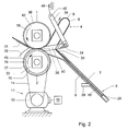
- Fig. 2 shows the buckling into a loop 6 of the first section 9 of the sheet 4, which first section, measured along the sheet 4, is situated closer to the folding nip 3 than is the second section 10.
- the folding rollers 1, 2 are rotated further in the input rotation sense indicated by arrows 18, 19, whereby portions of the sheet 4 situated between the folding rollers 1, 2 are transported with a directional component in a direction towards the second section 10.
- a portion of the sheet 4 downstream of the folding rollers 1, 2 is stopped in that it butts against the stop 20 in the buckle chute 5.
- Such arrest can also be implemented in a different manner, for instance by clamping a portion of the sheet 4 downstream of the folding rollers 1, 2, for instance by means of a gripper or between transport rollers.
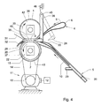
- the folding rollers 1, 2 are rotated in an output rotation sense (arrows 25, 26 in Fig. 4), whereby the sections of the folding rollers 1, 2 in the area of the folding nip 3 transport the second section 10 into the folding nip 3 and a first fold 28 (see Fig. 4) is formed.
- the folding rollers 1, 2 proceed to rotate further, so that also the first section 9 of the sheet 4 is transported through the folding nip 3 and a second fold, spaced from said first fold, is formed, in that the loop 6 is folded flat.
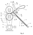
- Rotating the folding rollers 1, 2 in the output rotation sense is preferably started simultaneously with or after the second section 10 has been urged to the folding nip 3, so that the first fold 28 comes to lie close to the edge of the sheet 4 which has not passed the folding nip 3.
- the folding blade 24 is moved back to its initial position. This can for instance be done during the introduction of a next sheet 4 to be folded.
- the buckle chute 5 is equipped with a flexible sheet catcher 29 which, when the sheet 4 passes into the buckle chute, bends away owing to the pressure of the sheet 4, and hence gives the sheet 4 room to move past the catcher 29.
- the catcher 29 retains the sheet 4 by wedge action, so firmly as to prevent its moving away from the stop 20 in the buckle chute 5.
- the buckle chute 5 has at its inlet a flexible guide 30, by which the sheet 4, when being introduced via the folding nip 3, is guided into the buckle chute 5. Because the path along which the folding blade 24 is reciprocable intersects the guide 30, the guide 30 is made so flexible as to be elastically bent when the folding blade 24 is moved to the folding nip 3 for urging the second section 10 of the sheet 4 to the folding nip 3. When the folding blade 24 moves back again, the elastic guide 30 springs back again.
- the flexible guide 30 moreover yields during the formation of the loop 6 (see Fig. 2), so that the loop 6 is easily formed and unintended formation of buckles in the sheet 4 is prevented.
- the size of the loop 6 determines the position of the second fold and is determined by the moment when the folding rollers 1, 2 stop feeding through.
- the drive of the blade 24 includes inter alia the motor 13, as well as a transmission which is coupled with the folding blade 24 for selectively driving displacements of the folding blade 24 towards the folding nip 3 and away from the folding nip 3 and with the folding rollers 1, 2 for each time at or after one of the displacements of the blade 24 reversing the rotation sense in which the folding rollers 1, 2 are driven.
- the motor 13 as well as a transmission which is coupled with the folding blade 24 for selectively driving displacements of the folding blade 24 towards the folding nip 3 and away from the folding nip 3 and with the folding rollers 1, 2 for each time at or after one of the displacements of the blade 24 reversing the rotation sense in which the folding rollers 1, 2 are driven.
- the transmission is equipped with a carrier pawl 35 which is coupled with the folding blade 24 via carrier arms 40, 41, and a pair of circulating surfaces 36, 37, in the form of circumferential surfaces 36, 37 of carrier wheels 42, 43 which are coupled via the clutch 16 with the folding rollers 1, 2, for circulation in a circulation sense which corresponds to the rotation sense of the folding rollers 1, 2, and which define a carrier area 44 situated between the circulating surfaces 36, 37 (see Fig. 5).
- the carrier pawl 35 is movable relative to the circulating surfaces 36, 37, between positions on opposite sides of the carrier area 44.
- the circulating surfaces 36, 37 in the carrier area 44 are arranged, upon reversal of the circulation sense of the circulating surfaces 36, 37, to engage between them the carrier pawl 35 from one of the opposite sides of the carrier area 44 (see Figs. 1-3) to the other one of the opposite sides of the carrier area 44 (see Fig. 4).
- the folding blade 24 is suspended so as to be pivotable about an axis 45 with respect to a fixed frame part of the apparatus via arms 38, 39.
- a spring 46 is provided which urges the arms 38, 39 to a position in which the carrier pawl 35 coupled thereto is situated in the carrier area 44.
- the spring 46 has an end which is attached to a fixed frame part of the apparatus and an end which is attached to the arms 38, 39.
- the carrier pawl 35 is carried along by the circumferential surfaces 36, 37 of the carrier wheels 42, 43 through the carrier area 44.
- the spring 46 then ensures that the carrier pawl 35 always rests against the circumferential surfaces 36, 37 with enough pressure to be carried along by these surfaces through the carrier area 44.
- the circulating surfaces that carry the carrier pawl along are part of the folding rollers.
- the circulating surfaces 36, 37 each form part of an element 42, 43 separate from the folding rollers 1, 2 and are coupled with the folding rollers 1, 2, for starting at least rotation of the folding rollers 1, 2 in the output rotation sense 25 after circulation of the elements 36, 37 in the corresponding circulation sense has started and the carrier pawl 35 has thereby been carried along from one of the opposite sides of the carrier area 44 to the other one of the opposite sides of the carrier area 44.
- This provides the advantage that it is ensured that a portion of a sheet 4 in which a fold 28 is to be provided has been brought into a controlled position close to the folding nip 3, from where the sheet is reliably pulled into the folding nip 3 when rotation of the folding rollers 1, 2 is started. This in turn is advantageous for the accurate control of the position where the fold is provided.
- the delayed start of rotation of the folding rollers 1, 2 upon reversal of rotation of the carrier wheels 42, 43 to the output rotation sense is obtained, according to this example, by the earlier-described lost motion clutch 16 which is included between the carrier wheel 43 and the folding roller 2.
- This lost motion clutch 16 allows a free angular displacement between the input shaft 33 and the output shaft 34, in the nature of play through a rotation angle.
- a portion of the second section 10, prior to the movement of the folding blade 24, is deflected, with respect to a transport plane extending through the folding nip 3 and at right angles to a plane determined by axes of the folding rollers 1, 2, in a first direction, and the first section 9 is deflected with respect to that transport plane in a second direction opposite to this first direction.
- the two parts of the sheet 4 are thus deflected in opposite directions, forming the loop 6 and urging the second section 10 of the sheet 4 towards the folding nip 3 prior to the actual formation of the folds requires relatively small maximum bending of the sheet 4, which is advantageous for a reliable operation and limiting the risk of damage or curling of the sheet.
- the apparatus according to the example shown is further equipped with guides 31, 32 which determine an input path and an output path for inputting a sheet 4 along an input path from a side of the folding nip 3 opposite to the side of the folding nip 3 where the first section 9 is buckled into a loop 6 and for outputting the sheet 4 along an output path other than the input path on a side of the folding nip 3 opposite to the side of the folding nip 3 where the first section 9 has been buckled into a loop 6.
Landscapes
- Folding Of Thin Sheet-Like Materials, Special Discharging Devices, And Others (AREA)
Abstract
Description
- The invention relates to a method for folding sheets of paper according to the introductory portion of
claim 1, and to an apparatus for folding sheets of paper according to the introductory portion ofclaim 7. Such a method and apparatus are known from U.S. Patent 5,490,829. - In that method and apparatus, a sheet to be folded is supplied via a nip between a pair of transport rollers and through a gap between a pair of pivotally suspended guides. When a leading portion of the sheets has arrived between a pair of folding rollers downstream of the guides, the folding rollers are stopped and the guides are pivoted while the transport rollers supply the paper over some further distance. This causes the sheet to buckle and results in a loop in the sheet.
- Next, the guides are swung back, whereby transport rollers arranged on the guides clamp the sheet against the one of the folding rollers that is situated on the side of the folding gap where also the loop has been formed and where the guides had been swung to. By proceeding to drive both the folding rollers and the transport rollers, a bend in the sheet is urged between the folding rollers, whereby a first fold is formed. Thereupon, the loop together with the rest of the sheet also passes through the folding gap, in which the trailing end of the loop is pressed flat, so that a second fold is formed. Thus, with a single folding gap, two folds are formed.
- It is an object of the invention to provide a more simply feasible solution for folding a sheet using a pair of folding rollers.
- This object is achieved according to the invention by providing a method according to
claim 1. The invention may also be embodied in an apparatus according toclaim 7, which is specifically arranged for carrying out the method according toclaim 1. - As in the method and apparatus according to the invention supplying the sheet is done by suitably driving the folding rollers, supplying the sheet does not require any separate set of transport rollers with associated drive. An additional advantage is that the sheets after folding are outputted on the side of the folding nip from where they have been supplied. This makes it simpler to realize a machine lay-out whereby input and output are situated on the same side of the machine, so that the user can perform both operations on the same side of the machine.
- Although in the foregoing reference has been made to folding a sheet, it will be clear to one skilled in the art that this should be understood to include the simultaneous folding of two or more sheets stacked onto each other. In principle, it makes no difference for the invention whether, in addition to the one sheet mentioned, any other sheets stacked onto it are simultaneously folded along with it.
- Features of particular embodiments of the invention are laid down in the dependent claims.
- Further features, effects and details of the invention are described in the detailed description.
-
- Figs. 1-4 are schematic, partially cutaway representations in side elevation of an example of a folding apparatus according to the invention in successive operating stages; and
- Fig. 5 is a schematic front view of a portion of the apparatus according to Figs. 1-4.
- The apparatus for folding a sheet of paper according to the example represented in the drawing is equipped with a pair of
folding rollers folding nip 3 situated between them. - For guiding a
sheet 4 extending through thefolding nip 3, a transport path is provided, which, according to this example, is formed byguides buckle chute 5. Thefolding rollers sheet 4, so that they can form a fold which extends throughout the width of thesheet 4. In this respect, folding rollers typically differ from transport rollers which are typically narrower than the greatest dimension transverse to the direction of transport of the sheets to be transported. - A
first section 9 of the sheet, measured along thesheet 4, is situated closer to thefolding nip 3 than asecond section 10. For causing thefirst section 9 of thesheet 4 to buckle into aloop 6, the apparatus is equipped with adrive 11 and acontrol 12. The drive according to this example is made up of amotor 13, adrive belt 14, apulley 15 which is connected with thefolding roller 2 for driving rotation thereof and aclutch 16 which connects the folding rollers with the motor, such that upon reversal of the rotation direction to the output direction the folding rollers are not driven until after theinput shaft 33 of the clutch has rotated through an angle. This angle can be, for instance, between 20° and 300°. According to this example, theclutch 16 is designed as a lost motion clutch, whoseoutput shaft 34 upon each reversal of the rotation direction of theinput shaft 33 is not carried along until after theinput shaft 33 has rotated through a certain angle. - The
drive 11 and thecontrol 12 are arranged for driving thefolding rollers arrows sheet 4 to buckle, the apparatus according to this example is equipped with a detainer in the form of astop 20 in thebuckle chute 5 for stopping, with respect to the portions of thesheet 4 transported between thefolding rollers sheet 4 in thetransport path folding rollers - According to this example, the stop is of fixed design, but, depending on the setting possibilities contemplated, may be manually or mechanically settable. The stop may for instance be coupled to the drive of the folding rollers, so that the stop travels along with the
sheet 4 up to the correct position. That position could be determined electronically, for instance by means of a pulse disc and a switching clutch. In this way, the folding process can be controlled wholly electronically and each fold can be different from the preceding one, thus yielding an extremely flexible folding system. The stop-clutch switches on at the moment when the paper enters and switches off after a particular number of pulses. At the moment when the folding rollers are going to reverse, the clutch switches on again and the stop travels back to its initial position. Having arrived there, the clutch switches off again, waiting for the next cycle. - It is also possible, for instance, to use a pair of rollers or a clamping member to stop the leading portion of the
sheet 4 when thesheet 4 is to be caused to buckle. - Means for bending the
second section 10 of thesheet 4 to the folding nip are formed, according to this example, by afolding blade 24 which is reciprocable between the positions represented in Figs. 1-3 and in Fig 4. - The
drive 11 and thecontrol 12 are further arranged for rotating thefolding rollers arrows second section 10 of thesheet 4 is transported into thefolding nip 3. - In operation, the folding of a sheet in the apparatus shown starts with introducing the
sheet 4 into the foldingnip 3 between thefolding rollers sheet 4 has already been transported over such a distance as to have nearly reached thestop 20. - Fig. 2 shows the buckling into a
loop 6 of thefirst section 9 of thesheet 4, which first section, measured along thesheet 4, is situated closer to thefolding nip 3 than is thesecond section 10. To this end, thefolding rollers arrows sheet 4 situated between thefolding rollers second section 10. With respect to the portions of thesheet 4 transported between thefolding rollers sheet 4 downstream of thefolding rollers stop 20 in thebuckle chute 5. Such arrest can also be implemented in a different manner, for instance by clamping a portion of thesheet 4 downstream of thefolding rollers - Rotating the
folding rollers sheet 4 is just being held between thefolding rollers second section 10 of thesheet 4 is urged towards thefolding nip 3. This is realized according to this example in that thefolding blade 24, on a side of thesheet 4 remote from thefolding nip 3, is moved towards thefolding nip 3, as indicated in Fig. 3 with anarrow 27. Thus, introducing thesecond section 10 of the sheet into the folding nip is accurately controlled with simple means. - The
folding rollers arrows folding rollers folding nip 3 transport thesecond section 10 into thefolding nip 3 and a first fold 28 (see Fig. 4) is formed. Thefolding rollers first section 9 of thesheet 4 is transported through thefolding nip 3 and a second fold, spaced from said first fold, is formed, in that theloop 6 is folded flat. Rotating thefolding rollers second section 10 has been urged to thefolding nip 3, so that thefirst fold 28 comes to lie close to the edge of thesheet 4 which has not passed thefolding nip 3. - When the
sheet 4 has been outputted, thefolding blade 24 is moved back to its initial position. This can for instance be done during the introduction of anext sheet 4 to be folded. - Within the framework of the invention, it is also possible to provide only a single fold in the
sheet 4. To that end, the transport of thesheet 4 by thefolding rollers sheet 4 has passed through thenip 3 between thefolding rollers sheet 4 and possibly supported by rotation of thefolding roller 1, to a position extending along the folding rollers on the side of thefolding blade 24. The provision of the fold is thereupon effected correspondingly to the provision of thefirst fold 28 in the above-described example. - For the accurate control of the position where the second fold is provided, it is advantageous to prevent the sheet being moved out of the
buckle chute 5 prematurely due to thesecond section 10 thereof being urged to the folding nip 3. To that end, thebuckle chute 5 is equipped with aflexible sheet catcher 29 which, when thesheet 4 passes into the buckle chute, bends away owing to the pressure of thesheet 4, and hence gives thesheet 4 room to move past thecatcher 29. When the second section of thesheet 4 is urged towards the folding nip 3, thecatcher 29 retains thesheet 4 by wedge action, so firmly as to prevent its moving away from thestop 20 in thebuckle chute 5. When the folding rollers engage thesecond section 10, however, and pull it into the folding nip 3, the holding force exerted on thesheet 24 by thecatcher 29 is overcome and thesheet 4 passes out of thebuckle chute 5. - The
buckle chute 5 has at its inlet aflexible guide 30, by which thesheet 4, when being introduced via the folding nip 3, is guided into thebuckle chute 5. Because the path along which thefolding blade 24 is reciprocable intersects theguide 30, theguide 30 is made so flexible as to be elastically bent when thefolding blade 24 is moved to the folding nip 3 for urging thesecond section 10 of thesheet 4 to the folding nip 3. When thefolding blade 24 moves back again, theelastic guide 30 springs back again. Theflexible guide 30 moreover yields during the formation of the loop 6 (see Fig. 2), so that theloop 6 is easily formed and unintended formation of buckles in thesheet 4 is prevented. - The size of the
loop 6 determines the position of the second fold and is determined by the moment when thefolding rollers - According to this example, the drive of the
blade 24 includes inter alia themotor 13, as well as a transmission which is coupled with thefolding blade 24 for selectively driving displacements of thefolding blade 24 towards the folding nip 3 and away from the folding nip 3 and with thefolding rollers blade 24 reversing the rotation sense in which thefolding rollers folding blade 24. - According to this example, the transmission is equipped with a
carrier pawl 35 which is coupled with thefolding blade 24 viacarrier arms surfaces circumferential surfaces carrier wheels folding rollers folding rollers carrier area 44 situated between the circulatingsurfaces 36, 37 (see Fig. 5). Thecarrier pawl 35 is movable relative to the circulatingsurfaces carrier area 44. To this end, the circulatingsurfaces carrier area 44 are arranged, upon reversal of the circulation sense of the circulatingsurfaces carrier pawl 35 from one of the opposite sides of the carrier area 44 (see Figs. 1-3) to the other one of the opposite sides of the carrier area 44 (see Fig. 4). Thefolding blade 24 is suspended so as to be pivotable about anaxis 45 with respect to a fixed frame part of the apparatus viaarms spring 46 is provided which urges thearms carrier pawl 35 coupled thereto is situated in thecarrier area 44. Thespring 46 has an end which is attached to a fixed frame part of the apparatus and an end which is attached to thearms - Starting from the position represented in Figs. 1-3, upon reversal of the rotation sense of the
motor 13, whereby also the rotation sense of thecarrier wheels carrier pawl 35 is carried along by thecircumferential surfaces carrier wheels carrier area 44. Thespring 46 then ensures that thecarrier pawl 35 always rests against thecircumferential surfaces carrier area 44. Upon renewed reversal of the rotation sense of themotor 12 and thecarrier wheels carrier pawl 35 is carried along to the other side of thecarrier area 44 again, whereby thefolding blade 24 coupled to thecarrier pawl 35 returns from the position for introducing a portion of a sheet between thefolding rollers folding rollers - It is noted that it is also possible to provide that the circulating surfaces that carry the carrier pawl along are part of the folding rollers. However, it is preferred that, as in the exemplary embodiment shown, the circulating
surfaces element folding rollers folding rollers folding rollers output rotation sense 25 after circulation of theelements carrier pawl 35 has thereby been carried along from one of the opposite sides of thecarrier area 44 to the other one of the opposite sides of thecarrier area 44. This provides the advantage that it is ensured that a portion of asheet 4 in which afold 28 is to be provided has been brought into a controlled position close to the folding nip 3, from where the sheet is reliably pulled into the folding nip 3 when rotation of thefolding rollers - The delayed start of rotation of the
folding rollers carrier wheels carrier wheel 43 and thefolding roller 2. This lostmotion clutch 16 allows a free angular displacement between theinput shaft 33 and theoutput shaft 34, in the nature of play through a rotation angle. - According to the example represented, a portion of the
second section 10, prior to the movement of thefolding blade 24, is deflected, with respect to a transport plane extending through the folding nip 3 and at right angles to a plane determined by axes of thefolding rollers first section 9 is deflected with respect to that transport plane in a second direction opposite to this first direction. As the two parts of thesheet 4 are thus deflected in opposite directions, forming theloop 6 and urging thesecond section 10 of thesheet 4 towards the folding nip 3 prior to the actual formation of the folds requires relatively small maximum bending of thesheet 4, which is advantageous for a reliable operation and limiting the risk of damage or curling of the sheet. - The apparatus according to the example shown is further equipped with
guides sheet 4 along an input path from a side of the folding nip 3 opposite to the side of the folding nip 3 where thefirst section 9 is buckled into aloop 6 and for outputting thesheet 4 along an output path other than the input path on a side of the folding nip 3 opposite to the side of the folding nip 3 where thefirst section 9 has been buckled into aloop 6. - This makes it possible to input the
sheet 4 from a side of the folding nip 3 opposite to the side of the folding nip 3 where thefirst section 9 is buckled into aloop 6, and to output the foldedsheet 4 on that side as well, while thesheet 4, after folding, leaves the folding nip 3 along an output path other than the input path. Input and output can therefore be done on the same side of the folding nip 3 and yet along different paths. As a consequence, the apparatus is simple in use and the output of a sheet does not hinder the input of a next sheet.
Claims (12)
- A method for folding a sheet of paper, comprising:supplying a sheet (4) between a pair of rotating rollers (1, 2);buckling a first section (9) of the sheet (4) into a loop (6) during rotation of the rollers (1, 2), and stopping with respect to portions of the sheet (4) transported between the rollers (1, 2) a portion of the sheet (4) remotely downstream of the folding rollers (1, 2);bending a second section (10) of the sheet (4) situated between opposite ends of the sheet (4) on a side of the loop (6) remote from the folding rollers (1, 2) to a folding nip (3) between a pair of folding rollers (1, 2);rotating the folding rollers (1, 2) in an output rotation sense, whereby sections of the folding rollers (1, 2) in the area of the folding nip (3) transport said bent second section (10) of the sheet (4) into the folding nip (3); andtransporting the bent portion of the sheet (4) through the folding nip (3), whereby a first fold (28) is formed in said second section (10) of the sheet (4) and subsequently a trailing end of the loop (6) is deformed into a second fold;characterized in that the rotating rollers (1, 2) between which at least a portion of the sheet (4) is supplied are the folding rollers (1, 2) which, prior to rotation in the output rotation sense, rotate in an input rotation sense opposite to the output rotation sense, causing the first section (9) of the sheet (4) to buckle into the loop (6) by, during rotation of the folding rollers (1, 2) in the input rotation sense, stopping with respect to portions of the sheet (4) transported between the folding rollers (1, 2) a portion of the sheet (4) remotely downstream of the folding rollers (1, 2).
- A method according to claim 1, wherein urging said portion of the sheet (4) to the folding nip (3) is carried out by moving a folding blade, on a side of the sheet (4) remote from the folding nip (3), to the folding nip (3).
- A method according to claim 2, wherein a portion of the second section (10), prior to movement of the folding blade, is deflected, with respect to a transport plane extending through the folding nip (3) and at right angles to a plane defined by axes of the folding rollers (1, 2), to a first side of said transport plane and wherein the first section (9) is deflected, with respect to the transport plane, to a second side of said transport plane, opposite said first side.
- A method according to any one of the preceding claims, further comprising inputting the sheet (4) from a side of the folding nip (3) opposite to the side of the folding nip (3) where a portion of the sheet (4) situated between opposite ends of the sheet (4) is bent to the folding nip (3).
- A method according to any one of the preceding claims, further comprising outputting the folded sheet (4) on a side of the folding nip (3) opposite to the side of the folding nip (3) where a portion of the sheet (4) situated between opposite ends of the sheet (4) is bent to the folding nip (3).
- A method according to claims 5 and 6, wherein the sheet (4) is passed along an input path to the folding nip (3) and, after folding, leaves the folding nip (3) along an output path other than the input path.
- An apparatus for folding a sheet of paper, comprising:a pair of folding rollers (1, 2) which define a folding nip (3) situated therebetween;a transport path for guiding a sheet (4) extending through the folding nip (3);means for causing a first section (9) of the sheet (4) to buckle into a loop (6);means for bending a second section (10) of the sheet (4) situated between opposite ends of the sheet (4) on a side of the loop (6) remote from the folding rollers (1, 2) to the folding nip (3); anda drive (11) coupled with the folding rollers (1, 2), with a control (12) for rotating the folding rollers (1, 2) in an output rotation sense, whereby the bent portion of the sheet (4) is transported through the folding nip (3) and a first fold is formed in said second section (10) and subsequently a trailing end of the loop (6) is deformed into a second fold;characterized by means remotely downstream of the folding rollers (1, 2), for, during rotation of the folding rollers (1, 2) in an input rotation sense for the supplying of the sheet (4), stopping a portion of the sheet (4) with respect to portions of the sheet (4) transported between the folding rollers (1, 2), for causing the first section (9) of the sheet (4) to buckle into the loop (6);
wherein the drive (11) and the control (12) are arranged for, prior to rotating the folding rollers (1, 2) in the output rotation sense, rotating the folding rollers (1, 2) in an input rotation sense opposite to the output rotation sense for supplying at least a portion of the sheet (4) between and through the folding rollers (1, 2). - An apparatus according to claim 7, further comprising guides which define an input path and an output path for inputting along an input path a sheet (4) from a side of the folding nip (3) opposite to the side of the folding nip (3) where the first section (9) is buckled into a loop (6) and for outputting the sheet (4) along an output path other than the input path on a side of the folding nip (3) opposite to the side of the folding nip (3) where the first section (9) has been buckled into a loop (6).
- An apparatus according to claims 7 or 8, further comprising a folding blade (24) which is movable from a position remote from the folding nip (3) to a position closer to the folding nip (3) for bending said portion of the sheet (4) to the folding nip (3).
- An apparatus according to claim 9, wherein said drive (11) comprises: a motor which is coupled via a transmission with the folding blade for selectively driving displacements of the folding blade (24) towards the folding nip (3) and away from the folding nip (3) and with the folding rollers (1, 2) for reversing the rotation sense in which the folding rollers (1, 2) are driven, each time at or after one of said displacements.
- An apparatus according to claim 10, wherein the transmission comprises:a carrier pawl (35) which is coupled with the folding blade (24), anda pair of circulating surfaces (36, 37) which are coupled with or are part of the folding rollers (1, 2) for circulation in a circulation sense corresponding to the rotation sense of the folding rollers (1, 2) and which define a carrier area (44) situated between said circulating surfaces (36, 37),wherein the carrier pawl (35) is movable along said circulating surfaces between positions situated on opposite sides of the carrier area,
wherein said circulating surfaces (36, 37) in the carrier area (44) are arranged for engaging the carrier pawl for, upon reversal of the circulation sense of the circulating surfaces (36, 37), carrying along between them the carrier pawl (35) from one of the opposite sides of the carrier area to the other one of said opposite sides of the carrier area. - An apparatus according to claim 11, wherein said circulating surfaces each form part of an element separate from the folding rollers (1, 2), which is coupled with the folding rollers (1, 2), for starting at least rotation of the folding rollers (1, 2) in the output rotation sense after circulation of the element in the corresponding circulation sense has started and the carrier pawl (35) has thereby been carried along from one of the opposite sides of the carrier area to the other one of said opposite sides of the carrier area.
Applications Claiming Priority (1)
| Application Number | Priority Date | Filing Date | Title |
|---|---|---|---|
| NL1027939A NL1027939C2 (en) | 2004-12-31 | 2004-12-31 | Method and device for folding sheets of paper. |
Publications (2)
| Publication Number | Publication Date |
|---|---|
| EP1676802A1 true EP1676802A1 (en) | 2006-07-05 |
| EP1676802B1 EP1676802B1 (en) | 2008-07-16 |
Family
ID=34974839
Family Applications (1)
| Application Number | Title | Priority Date | Filing Date |
|---|---|---|---|
| EP05078027A Expired - Lifetime EP1676802B1 (en) | 2004-12-31 | 2005-12-28 | Method and apparatus for folding sheets of paper |
Country Status (4)
| Country | Link |
|---|---|
| US (1) | US7326166B2 (en) |
| EP (1) | EP1676802B1 (en) |
| DE (1) | DE602005008183D1 (en) |
| NL (1) | NL1027939C2 (en) |
Cited By (1)
| Publication number | Priority date | Publication date | Assignee | Title |
|---|---|---|---|---|
| JP2020196587A (en) * | 2019-06-03 | 2020-12-10 | キヤノンファインテックニスカ株式会社 | Sheet folding device |
Families Citing this family (10)
| Publication number | Priority date | Publication date | Assignee | Title |
|---|---|---|---|---|
| DE102006028123A1 (en) * | 2006-06-15 | 2007-12-20 | JÜRG PAUL Haller | Device for manipulating flat piece goods, such as sheets of paper, plastic, cardboard and the like |
| US20090062099A1 (en) * | 2007-08-29 | 2009-03-05 | Kabushiki Kaisha Toshiba | Folding roller for sheet processing apparatus |
| FR2921353B1 (en) * | 2007-09-24 | 2010-06-18 | Goss Int Montataire Sa | FOLDING ROLL AND CORRESPONDING BENDER |
| JP5158065B2 (en) * | 2009-12-18 | 2013-03-06 | コニカミノルタビジネステクノロジーズ株式会社 | Post-processing equipment |
| US9199822B1 (en) | 2010-12-14 | 2015-12-01 | Express Scripts, Inc. | Systems and methods for folding a stack of substrate sheets |
| JP6102101B2 (en) * | 2012-07-12 | 2017-03-29 | 富士ゼロックス株式会社 | Paper processing apparatus and image forming system |
| JP2014162577A (en) * | 2013-02-22 | 2014-09-08 | Riso Kagaku Corp | Sheet folding device |
| US9373065B1 (en) | 2015-07-08 | 2016-06-21 | Express Scripts, Inc. | Paper feed system and method |
| US10850939B2 (en) | 2019-02-08 | 2020-12-01 | Express Scripts Strategic Development, Inc. | Systems and methods for folding a stack of substrate sheets |
| US11414294B2 (en) | 2019-12-31 | 2022-08-16 | Dmt Solutions Global Corporation | System and method for folding paper carriers with attached cards |
Citations (4)
| Publication number | Priority date | Publication date | Assignee | Title |
|---|---|---|---|---|
| JPS631675A (en) * | 1986-06-19 | 1988-01-06 | Seven Eng:Kk | Sheet folding device |
| EP0312177A1 (en) * | 1987-10-14 | 1989-04-19 | Hadewe B.V. | A method and an apparatus for folding paperlike material, such as documents, which may differ in quality and length and which are conveyed in assembled form or successively |
| US5490829A (en) | 1993-05-03 | 1996-02-13 | Secap | Document folding machine employing a flap |
| DE19837238A1 (en) * | 1998-08-17 | 2000-02-24 | Bruno A Weber | Apparatus for folding a sheet of paper into a loop which is folded, using least two rollers |
Family Cites Families (3)
| Publication number | Priority date | Publication date | Assignee | Title |
|---|---|---|---|---|
| NL8902476A (en) * | 1989-10-05 | 1991-05-01 | Hadewe Bv | METHOD AND DEVICE FOR FOLDING SHEETS. |
| US6024682A (en) * | 1998-11-23 | 2000-02-15 | Xerox Corporation | Automatically continuously variable fold position sheet folding system with automatic length and skew correction |
| US6592506B1 (en) * | 2002-06-25 | 2003-07-15 | Pitney Bowes Inc. | Folder apparatus |
-
2004
- 2004-12-31 NL NL1027939A patent/NL1027939C2/en not_active IP Right Cessation
-
2005
- 2005-12-28 EP EP05078027A patent/EP1676802B1/en not_active Expired - Lifetime
- 2005-12-28 DE DE602005008183T patent/DE602005008183D1/en not_active Expired - Lifetime
- 2005-12-28 US US11/320,551 patent/US7326166B2/en not_active Expired - Lifetime
Patent Citations (4)
| Publication number | Priority date | Publication date | Assignee | Title |
|---|---|---|---|---|
| JPS631675A (en) * | 1986-06-19 | 1988-01-06 | Seven Eng:Kk | Sheet folding device |
| EP0312177A1 (en) * | 1987-10-14 | 1989-04-19 | Hadewe B.V. | A method and an apparatus for folding paperlike material, such as documents, which may differ in quality and length and which are conveyed in assembled form or successively |
| US5490829A (en) | 1993-05-03 | 1996-02-13 | Secap | Document folding machine employing a flap |
| DE19837238A1 (en) * | 1998-08-17 | 2000-02-24 | Bruno A Weber | Apparatus for folding a sheet of paper into a loop which is folded, using least two rollers |
Non-Patent Citations (1)
| Title |
|---|
| PATENT ABSTRACTS OF JAPAN vol. 012, no. 195 (M - 705) 7 June 1988 (1988-06-07) * |
Cited By (1)
| Publication number | Priority date | Publication date | Assignee | Title |
|---|---|---|---|---|
| JP2020196587A (en) * | 2019-06-03 | 2020-12-10 | キヤノンファインテックニスカ株式会社 | Sheet folding device |
Also Published As
| Publication number | Publication date |
|---|---|
| US7326166B2 (en) | 2008-02-05 |
| DE602005008183D1 (en) | 2008-08-28 |
| EP1676802B1 (en) | 2008-07-16 |
| US20060148630A1 (en) | 2006-07-06 |
| NL1027939C2 (en) | 2006-07-03 |
Similar Documents
| Publication | Publication Date | Title |
|---|---|---|
| JP4088206B2 (en) | Paper folding device, paper processing device, and image forming system | |
| EP1676802B1 (en) | Method and apparatus for folding sheets of paper | |
| US7862022B2 (en) | Sheet processing apparatus and image forming apparatus | |
| JP2000103560A (en) | Paper ejection device | |
| CN102367115A (en) | Sheet folding apparatus | |
| CN101293607B (en) | Sheet post processing apparatus and image forming system | |
| JP2008156114A (en) | Paper post-processing device | |
| JP2010024011A (en) | Paper processor | |
| US7470227B2 (en) | Paper folding apparatus and image forming apparatus using the same | |
| US7173717B2 (en) | Sheet post-processing apparatus and image forming apparatus equipped with the same | |
| US20100295231A1 (en) | Paper sheet handling device | |
| JP4932675B2 (en) | Sheet processing apparatus and image forming apparatus | |
| JP2004106991A (en) | Paper processing apparatus and image forming system | |
| JP4976246B2 (en) | Sheet processing device | |
| JP2013154981A (en) | Sheet processing apparatus, image forming system, and sheet stacking method | |
| JP4355255B2 (en) | Paper processing apparatus and image forming apparatus | |
| JP3660868B2 (en) | Paper folding device | |
| US20030016402A1 (en) | Sheet post-processing apparatus and image forming apparatus equipped with the same | |
| JPH09208115A (en) | Post-processing device for image forming apparatus | |
| JP4405431B2 (en) | Paper transport device and paper transport method | |
| JP7340961B2 (en) | sheet folding device | |
| JP5553003B2 (en) | Paper processing device | |
| JP2012246083A (en) | Sheet postprocessing device and image forming apparatus | |
| JP4890417B2 (en) | Sheet member processing apparatus and image forming system apparatus | |
| JPH05319684A (en) | Paper folding device |
Legal Events
| Date | Code | Title | Description |
|---|---|---|---|
| PUAI | Public reference made under article 153(3) epc to a published international application that has entered the european phase |
Free format text: ORIGINAL CODE: 0009012 |
|
| AK | Designated contracting states |
Kind code of ref document: A1 Designated state(s): AT BE BG CH CY CZ DE DK EE ES FI FR GB GR HU IE IS IT LI LT LU LV MC NL PL PT RO SE SI SK TR |
|
| AX | Request for extension of the european patent |
Extension state: AL BA HR MK YU |
|
| 17P | Request for examination filed |
Effective date: 20061228 |
|
| AKX | Designation fees paid |
Designated state(s): DE FR GB |
|
| GRAP | Despatch of communication of intention to grant a patent |
Free format text: ORIGINAL CODE: EPIDOSNIGR1 |
|
| GRAS | Grant fee paid |
Free format text: ORIGINAL CODE: EPIDOSNIGR3 |
|
| GRAA | (expected) grant |
Free format text: ORIGINAL CODE: 0009210 |
|
| AK | Designated contracting states |
Kind code of ref document: B1 Designated state(s): DE FR GB |
|
| REG | Reference to a national code |
Ref country code: GB Ref legal event code: FG4D |
|
| REF | Corresponds to: |
Ref document number: 602005008183 Country of ref document: DE Date of ref document: 20080828 Kind code of ref document: P |
|
| PLBE | No opposition filed within time limit |
Free format text: ORIGINAL CODE: 0009261 |
|
| STAA | Information on the status of an ep patent application or granted ep patent |
Free format text: STATUS: NO OPPOSITION FILED WITHIN TIME LIMIT |
|
| 26N | No opposition filed |
Effective date: 20090417 |
|
| REG | Reference to a national code |
Ref country code: FR Ref legal event code: PLFP Year of fee payment: 11 |
|
| REG | Reference to a national code |
Ref country code: DE Ref legal event code: R082 Ref document number: 602005008183 Country of ref document: DE Representative=s name: CBDL PATENTANWAELTE, DE |
|
| REG | Reference to a national code |
Ref country code: DE Ref legal event code: R082 Ref document number: 602005008183 Country of ref document: DE Representative=s name: CBDL PATENTANWAELTE, DE Ref country code: DE Ref legal event code: R081 Ref document number: 602005008183 Country of ref document: DE Owner name: NEOPOST TECHNOLOGIES S.A., FR Free format text: FORMER OWNER: NEOPOST S.A., BAGNEUX, FR |
|
| REG | Reference to a national code |
Ref country code: FR Ref legal event code: PLFP Year of fee payment: 12 |
|
| REG | Reference to a national code |
Ref country code: FR Ref legal event code: PLFP Year of fee payment: 13 |
|
| REG | Reference to a national code |
Ref country code: DE Ref legal event code: R082 Ref document number: 602005008183 Country of ref document: DE Representative=s name: CBDL PATENTANWAELTE GBR, DE Ref country code: DE Ref legal event code: R082 Ref document number: 602005008183 Country of ref document: DE Representative=s name: CBDL PATENTANWAELTE EGBR, DE |
|
| PGFP | Annual fee paid to national office [announced via postgrant information from national office to epo] |
Ref country code: DE Payment date: 20241210 Year of fee payment: 20 |
|
| PGFP | Annual fee paid to national office [announced via postgrant information from national office to epo] |
Ref country code: GB Payment date: 20241227 Year of fee payment: 20 |
|
| PGFP | Annual fee paid to national office [announced via postgrant information from national office to epo] |
Ref country code: FR Payment date: 20241223 Year of fee payment: 20 |
|
| REG | Reference to a national code |
Ref country code: DE Ref legal event code: R071 Ref document number: 602005008183 Country of ref document: DE |
|
| REG | Reference to a national code |
Ref country code: GB Ref legal event code: PE20 Expiry date: 20251227 |