EP1676748A1 - A device for creating an angular biasing force - Google Patents
A device for creating an angular biasing force Download PDFInfo
- Publication number
- EP1676748A1 EP1676748A1 EP05028473A EP05028473A EP1676748A1 EP 1676748 A1 EP1676748 A1 EP 1676748A1 EP 05028473 A EP05028473 A EP 05028473A EP 05028473 A EP05028473 A EP 05028473A EP 1676748 A1 EP1676748 A1 EP 1676748A1
- Authority
- EP
- European Patent Office
- Prior art keywords
- torsion
- force
- torsion spring
- units
- spring
- Prior art date
- Legal status (The legal status is an assumption and is not a legal conclusion. Google has not performed a legal analysis and makes no representation as to the accuracy of the status listed.)
- Granted
Links
Images


Classifications
-
- B—PERFORMING OPERATIONS; TRANSPORTING
- B60—VEHICLES IN GENERAL
- B60J—WINDOWS, WINDSCREENS, NON-FIXED ROOFS, DOORS, OR SIMILAR DEVICES FOR VEHICLES; REMOVABLE EXTERNAL PROTECTIVE COVERINGS SPECIALLY ADAPTED FOR VEHICLES
- B60J1/00—Windows; Windscreens; Accessories therefor
- B60J1/20—Accessories, e.g. wind deflectors, blinds
- B60J1/2011—Blinds; curtains or screens reducing heat or light intensity
- B60J1/2013—Roller blinds
- B60J1/2033—Roller blinds characterised by the spring motor
-
- B—PERFORMING OPERATIONS; TRANSPORTING
- B60—VEHICLES IN GENERAL
- B60R—VEHICLES, VEHICLE FITTINGS, OR VEHICLE PARTS, NOT OTHERWISE PROVIDED FOR
- B60R5/00—Compartments within vehicle body primarily intended or sufficiently spacious for trunks, suit-cases, or the like
- B60R5/04—Compartments within vehicle body primarily intended or sufficiently spacious for trunks, suit-cases, or the like arranged at rear of vehicle
- B60R5/044—Compartments within vehicle body primarily intended or sufficiently spacious for trunks, suit-cases, or the like arranged at rear of vehicle luggage covering means, e.g. parcel shelves
- B60R5/045—Compartments within vehicle body primarily intended or sufficiently spacious for trunks, suit-cases, or the like arranged at rear of vehicle luggage covering means, e.g. parcel shelves collapsible or transformable
- B60R5/047—Compartments within vehicle body primarily intended or sufficiently spacious for trunks, suit-cases, or the like arranged at rear of vehicle luggage covering means, e.g. parcel shelves collapsible or transformable collapsible by rolling-up
-
- E—FIXED CONSTRUCTIONS
- E06—DOORS, WINDOWS, SHUTTERS, OR ROLLER BLINDS IN GENERAL; LADDERS
- E06B—FIXED OR MOVABLE CLOSURES FOR OPENINGS IN BUILDINGS, VEHICLES, FENCES OR LIKE ENCLOSURES IN GENERAL, e.g. DOORS, WINDOWS, BLINDS, GATES
- E06B9/00—Screening or protective devices for wall or similar openings, with or without operating or securing mechanisms; Closures of similar construction
- E06B9/56—Operating, guiding or securing devices or arrangements for roll-type closures; Spring drums; Tape drums; Counterweighting arrangements therefor
- E06B9/60—Spring drums operated only by closure members
Definitions
- the present invention relates to a device for creating an angular biasing force and especially such a device for use with a security shade covering the cargo area of a motor vehicle to prevent viewing into the cargo area.
- a rear compartment or cargo area is provided for storing personal items.
- motor vehicle manufacturers typically provide a retractable security shade or flexible panel that can be extended to cover the cargo area and prevent anyone outside the vehicle from readily viewing stored articles.
- the device for connecting the roller tube of the security shade onto the transversely spaced sides of the cargo area routinely include a mechanism to rotationally bias the roller tube at each end so the shade tends to be in the retracted stored condition.
- These devices at each end of the shade often include a torsion spring for biasing the roller tube in the rotational direction for storing the shade.
- Wieczorek 5,464,052 and Price 5,934,354 are shown in Wieczorek 5,464,052 and Price 5,934,354.
- the normal shade retraction devices or mechanisms used in the automobile industry employ a single torsion spring at each end to exert the retraction biasing force on the roller tube supporting the security shade. Consequently, a different device with a different coefficient of rotational force is required for each of the various security shade installations.
- a different torsion spring is required to provide a different biasing force in the rotational direction. This situation necessitated engineering different torsional spring designs and modification of the volume or cavity used to mount the different sized torsion springs.
- the magnitude of angular rotation is also fixed at a given angle by the construction of the torsion spring at each end of the shade.
- each torsion spring was designed for a particular motor vehicle and the surrounding mechanism for mounting the security shade was custom designed for each installation.
- the present invention relates to a device for creating an angular biasing force overcoming the problems associated with prior torsion spring mechanisms used in the automobile industry for retracting security shades.
- a plurality of force units each involving a separate torsion spring are combined to adjust the total angular biasing force and/or the amount of rotation of a device of the type used in creating a biasing force for a security shade.
- an improved device for creating an angular biasing force for a roller tube of a security shade where the roller tube is a standard member rotatably mounted in a fixed inside structure of a motor vehicle.
- the device at each end of the shade includes an element attached to the fixed side structure of a vehicle and a plurality of force units each including a torsion spring exert a biasing force between the fixed structure of the vehicle and the roller tube of the security shade.
- Each of the torsion springs of the spaced devices has a first inner end associated with the fixed vehicle structure and a second outer end associated with the roller tube so the torsion biasing force of the spring is in a direction from the fixed structure to the roller tube.
- the total angular force of the device is the sum of the biasing forces of all the torsion spring force units.
- the torsion springs are connected from the first end to the second end in series. In this manner, the amount of rotation available during extension of the shade is adjusted by the number of series springs. Both concepts provide a biasing force equal to the force of a plurality of torsion springs.
- a selected number of torsion spring force units are used to adjust either the total angular biasing force or the amount of rotation available. Consequently, the biasing force or angular rotation of the device can be adjusted by selecting the number of torsion spring force units.
- the springs are connected in parallel.
- the springs are connected in series. This is the preferred design.
- the roller tube has an end housing with an inner cylindrical surface and each of the torsion spring force units has a support housing or spring receptacle with an outer cylindrical surface slidable in the inner cylindrical surface of the end housing for the roller tube.
- a fastener is used to selectively attach the force units to the end housing. The total force is thereby easily adjusted by adding or subtracting to the number of force units.
- the roller tube still has the same end housing with an inner cylindrical surface and each of the torsion spring force units still has a support housing or spring receptacle with an outer cylindrical surface slidable in the inner cylindrical surface of the end housing of the roller tube.
- the total angular rotation is a summation of the rotational travel of the plurality of torsion spring force units used in the device.
- the primary object of the present invention is the provision of a device for creating an angular force, which device utilizes a plurality of force units based upon torsional springs where the number of units can be varied to change the angular rotation and/or the angular biasing force.
- Yet another object of the present invention is the provision of a device for creating angular force, as defined above, which device involves the plurality of torsion springs connected in series or in parallel to add the torsional coefficient of force of the springs to obtain a total angular biasing force or to add the rotational displacement.
- Another object of the present invention is the provision of a device for creating an adjustable biasing force or rotation, as defined above, which device can be used for retracting a security shade for the cargo compartment of a motor vehicle.
- Still a further object of the present invention is the provision of a device for creating an angular force, as defined above, which device utilizes a series of force units based upon torsional springs wherein the number of torsional units can be changed to adjust the total angular rotation wherein the force units are easy to manufacture and duplicative in design.
- device A is constructed in accordance with the present invention for creating rotational biasing between fixed structure B, which is in practice an automobile sidewall of a cargo area and a roller tube C of a security shade used to cover the cargo area.
- Device A is used to create a rotational biasing force to wind a security shade onto roller tube C as the tube is rotated counterclockwise by using parallel torsion springs, as shown in FIGURE 3.
- the center, axially extending fixed member of device A is shaft 10 having a transverse slot 12 with an open end 12a and a closed end 12b. Opening 14 in fixed side mounting structure B receives the end of shaft 12 which is secured with respect to structure B by an appropriate set screw 16.
- Onto shaft 12 is mounted a plurality of force units 20, 22, 24 and 26, each of which is substantially identical and the number in device A can be increased or decreased to change the biasing force between fixed structure B and roller tube C.
- another device A is located on the opposite side of the cargo area so roller tube C extends across the cargo area and is biased by two devices A, with one device on opposite ends of roller tube C.
- the actual security shade wrapped on the roller tube is a common component and is not illustrated. Since each force unit 20, 22, 4 and 26 is the same, only unit 20 will be described and this description will apply equally to the other units. The number for parts of the units are the same.
- Support cup 30 has a forwardly facing counter bore 32 and a rearwardly extending boss 34.
- Torsion spring 50 is formed from a flat spring steel metal with a first end 52 formed into a straight portion for insertion into slot 12 of shaft 10 from end 12a. Before that assembly takes place, second end 54 of spring 50 having a tab 56 with a radially extending straight portion 56a is fitting into slot 42.
- Torsion spring 50 is first placed into the cavity 36 of cup or housing 30 by attaching its second end 54 at tab 56 onto the spring housing, as best shown in FIGURES 3 and 4. Then, force unit 20 is mounted onto fixed shaft 10 by sliding straight end 52 onto slot 12 from end 12a. The plurality of force units are assembled in parallel by first mounting torsion spring 50 into cup 30. Retainer 56b has a width a generally matching and slightly smaller than width b of flat surface 40. Thus, spring 50 is inserted into and retained on housing 30. Thereafter, the force unit is mounted in parallel on shaft 10 by inserting straight portion 52 in slot 12.
- Each end of tube C includes end housing portion 60 with an inner cylindrical surface 66. Support cups 30 have outer cylindrical surfaces 38 slightly less in diameter than surface 66 so units 20, 22, 24 and 26 freely slide into housing portion 60.
- the first assembly step for the parallel spring embodiment involves placing the torsion spring 50 of first force unit 20 into the cup or housing 30.
- Tab 56 slides through access end 42a of slot 42 until the tab is captured in flat portion 40 so torsion spring 50 has its second end 54 secured to housing 30.
- force unit 20 is slipped onto shaft 10 with flat first end 52 sliding into slot 12 of the shaft.
- the fixed shaft protrudes outwardly through opening 39 of housing 30 for receiving next force unit 22 having its torsion spring 50 already assembled into the next cup 30.
- Additional parallel force units 24 and 26 are then assembled onto shaft 10. This is accomplished in the same manner. With the four parallel force units in place, the units are then slid into tube C and locked onto the tube by set screws 64 in threaded openings 62.
- FIGURE 2 four force units are affixed to tube C so that the total biasing force is the summation of the torsion forces in the four separate units.
- each unit has the same coefficient of torsion force.
- First end 52 of each spring in parallel force units 20, 22, 24 and 26 is secured to fixed structure B byway of slotted shaft 10.
- Second ends 54 of the torsion springs are connected to roller tube C by way of housing 30 and set screw 64. Opening 39 has a diameter greater than shaft 10 so that cup 30 can easily rotate on the shaft through the parallel configured torsion springs as shown in FIGURES 1-4.
- FIGURE 2A The basic feature of the present invention is illustrated in FIGURE 2A where only three parallel force units 20, 22 and 24 are used to mount tube C onto fixed structure B.
- the torsion force on tube C is three-fourths the amount of biasing force created by the structure illustrated in FIGURE 2.
- the amount of biasing force can be adjusted easily by merely changing the number of units at each end of tube C. Indeed, the number of parallel force units at either end of tube C could be different; however, this parallel spring device is not the preferred implementation of the invention.
- the biasing force on the tube is adjusted. If the angular rotation to unwind the shade is to be increased, the series spring version of the invention is used and will be described in connection with FIGURES 5-8. Adjustment of force or amount of rotation is not possible in prior units such as shown in Price 5,934,354.
- the present invention, whether the parallel version or the series version requires no common housing for all springs but only separate force units individually mounted and operated by the roller tube. Cup 30 is only a mounting member and not an enclosure or housing.
- the preferred embodiment of the invention does not use the parallel connected force units as shown in FIGURES 1-4.
- the preferred implementation is device A' shown in FIGURES 5-8 uses a plurality of series connected torsion springs. This concept allows adjustment of the rotational angle during the unwinding of the shade.
- the actual torsion spring of device A' is essentially the same as the previously described torsion spring 50 used in the parallel spring version of the invention.
- force units 100, 102 and 104 are connected in series with a terminal connector unit 106 connecting the stack of force units onto end housing 60. Since series connected force units 100, 102 and 104 are structurally the same, only one of these units needs to be described. This description applies to the other force units arranged in series with connector unit 106.
- Torsion spring 50 is used in series units 100, 102 and 104.
- the force units have a cup 110.
- Cup 110 is used for fastener or connector unit 106.
- Cup 110 includes a counter bore 112 and bus 114 which fit together for aligning the units about the same axis. Opening 116 receives the nose 134 of an adjacent slotted shaft 132 after the various units have been assembled in series.
- Cup 110 has central cavity 118 for receiving torsional springs 50 and an outer cylindrical surface 120. From one end of cup 30 there is a mounting shaft 130 having a slot 132 and terminal small cylindrical nose 134. This nose fits into opening 116 of the prior force unit. Nose 134 rotates in opening 116.
- cup 110 has outer flat surface 124 with a radial slot 126 having an access end 126a so spring 50 can be assembled onto unit 100 (102, 104) by tab 56 fitting into slot 126, as best illustrated in FIGURE 8.
- shaft 130 is inserted into opening 140 of fixed structure B.
- set screw 142 then locks the first cup 110 onto structure B.
- the structure of force unit 100 is shown in FIGURE 8. This same structure is used for force units 102, 104 that are assembled in series as shown in FIGURE 6.
- connector unit 106 merely employs a spring cup 110 having a forwardly extending slot 130 with a nose 134 extending into opening 116 of the bottom portion of force unit 104.
- First end 52 of the three torsion springs are received in slot 132 of the successive cups 110, as shown in FIGURES 6 and 7.
- units 100, 102 and 104 are connected in series to exert a summation of forces between structure B and the empty cup 110 comprising the connector unit 106.
- This cup is affixed to end housing 60 by set screw 64.
- the rotational angle is the sum of the angle of each spring unit.
- Outer surfaces 120 of units 100, 102 , 104, and 106 are slidably received within cylindrical surface 66 of end housing 60 of roller tube C.
- FIGURES 1-4 connects the torsion springs in parallel.
- Preferred embodiments of the invention shown in FIGURES 5-8 use essentially the same type of structures, but are slightly modified so that the housing of one unit is rotatable with respect to the housing of the adjacent units.
- An advantage of the structure shown in FIGURES 5-8 is illustrated in FIGURE 6A. To reduce the total angle, only two series connected force units 100, 102 are used in device A'. Any number of series connected force units having the structure so far described, can be connected in device A' to provide a selected rotational angle.
- the first embodiment of the invention involves connecting torsion springs in parallel.
- the second and preferred embodiment involves connecting the torsion springs in series.
- the number of springs in each of these units can be varied so that a standard force unit is manufactured and the amount of torsional force or angular rotation is adjusted by the number of force units assembled into the device for creating the angular biasing force.
Abstract
Description
- The present invention relates to a device for creating an angular biasing force and especially such a device for use with a security shade covering the cargo area of a motor vehicle to prevent viewing into the cargo area.
- In many styles of motor vehicles, a rear compartment or cargo area is provided for storing personal items. To discourage viewing of the cargo area, motor vehicle manufacturers typically provide a retractable security shade or flexible panel that can be extended to cover the cargo area and prevent anyone outside the vehicle from readily viewing stored articles. The device for connecting the roller tube of the security shade onto the transversely spaced sides of the cargo area routinely include a mechanism to rotationally bias the roller tube at each end so the shade tends to be in the retracted stored condition. These devices at each end of the shade often include a torsion spring for biasing the roller tube in the rotational direction for storing the shade. Such devices are shown in Wieczorek 5,464,052 and Price 5,934,354. These two patents are incorporated by reference as background information and showing the type of mechanism to which the present invention is directed.
- The normal shade retraction devices or mechanisms used in the automobile industry employ a single torsion spring at each end to exert the retraction biasing force on the roller tube supporting the security shade. Consequently, a different device with a different coefficient of rotational force is required for each of the various security shade installations. A different torsion spring is required to provide a different biasing force in the rotational direction. This situation necessitated engineering different torsional spring designs and modification of the volume or cavity used to mount the different sized torsion springs. Furthermore, the magnitude of angular rotation is also fixed at a given angle by the construction of the torsion spring at each end of the shade. Thus, each torsion spring was designed for a particular motor vehicle and the surrounding mechanism for mounting the security shade was custom designed for each installation. This presents substantial engineering costs and a need for a large inventory of different torsion spring designs and different housings for devices using the different sized torsion springs. The custom designed torsion spring requirement also impacts the aftermarket. For instance, if a security shade is to be mounted in a particular motor vehicle, the aftermarket must provide a full host of different spring designs. Such lack of uniformity complicated the aftermarket and also increased the OEM cost and the device inventory requirements. As can be appreciated, there is a need for solving the problems associated with the diverse needs of devices to create a rotational force and angular movement to retract a security shade of the type now becoming quite popular. The prior art units increased the size of the housing at each end of the shade.
- The present invention relates to a device for creating an angular biasing force overcoming the problems associated with prior torsion spring mechanisms used in the automobile industry for retracting security shades. In accordance with the invention, a plurality of force units each involving a separate torsion spring are combined to adjust the total angular biasing force and/or the amount of rotation of a device of the type used in creating a biasing force for a security shade.
- In accordance with the present invention, there is provided an improved device for creating an angular biasing force for a roller tube of a security shade where the roller tube is a standard member rotatably mounted in a fixed inside structure of a motor vehicle. In accordance with the invention, the device at each end of the shade includes an element attached to the fixed side structure of a vehicle and a plurality of force units each including a torsion spring exert a biasing force between the fixed structure of the vehicle and the roller tube of the security shade. Each of the torsion springs of the spaced devices has a first inner end associated with the fixed vehicle structure and a second outer end associated with the roller tube so the torsion biasing force of the spring is in a direction from the fixed structure to the roller tube. When the springs are mounted in parallel, the total angular force of the device is the sum of the biasing forces of all the torsion spring force units. In the preferred embodiment, the torsion springs are connected from the first end to the second end in series. In this manner, the amount of rotation available during extension of the shade is adjusted by the number of series springs. Both concepts provide a biasing force equal to the force of a plurality of torsion springs.
- In accordance with a feature of the present invention, a selected number of torsion spring force units are used to adjust either the total angular biasing force or the amount of rotation available. Consequently, the biasing force or angular rotation of the device can be adjusted by selecting the number of torsion spring force units. There is no need to provide springs having different force coefficients, different amount of rotation and different dimensions for each security shade installation. To increase force, the springs are connected in parallel. To increase the angle of rotation, the springs are connected in series. This is the preferred design.
- When the force units involve torsion springs connected in parallel, the roller tube has an end housing with an inner cylindrical surface and each of the torsion spring force units has a support housing or spring receptacle with an outer cylindrical surface slidable in the inner cylindrical surface of the end housing for the roller tube. A fastener is used to selectively attach the force units to the end housing. The total force is thereby easily adjusted by adding or subtracting to the number of force units. When the torsion spring force units are connected in series, the roller tube still has the same end housing with an inner cylindrical surface and each of the torsion spring force units still has a support housing or spring receptacle with an outer cylindrical surface slidable in the inner cylindrical surface of the end housing of the roller tube. However, when the torsion units are connected in series, a fastener unit is attached to the last of the force units in the series of force units to connect the last unit with the end housing of the roller tube by the fastener unit. In this embodiment of the invention, the total angular rotation is a summation of the rotational travel of the plurality of torsion spring force units used in the device.
- The primary object of the present invention is the provision of a device for creating an angular force, which device utilizes a plurality of force units based upon torsional springs where the number of units can be varied to change the angular rotation and/or the angular biasing force.
- Yet another object of the present invention is the provision of a device for creating angular force, as defined above, which device involves the plurality of torsion springs connected in series or in parallel to add the torsional coefficient of force of the springs to obtain a total angular biasing force or to add the rotational displacement.
- Another object of the present invention is the provision of a device for creating an adjustable biasing force or rotation, as defined above, which device can be used for retracting a security shade for the cargo compartment of a motor vehicle.
- Still a further object of the present invention is the provision of a device for creating an angular force, as defined above, which device utilizes a series of force units based upon torsional springs wherein the number of torsional units can be changed to adjust the total angular rotation wherein the force units are easy to manufacture and duplicative in design.
- These and other objects and advantages will become apparent from the following description taken together with the accompanying drawings.
-
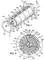
- FIGURE 1 is a pictorial view of the first embodiment of the invention wherein the force units are connected in parallel;
- FIGURE 2 is an enlarged cross-sectional view taken generally along line 2-2 of FIGURE 1;
- FIGURE 2A is a view similar to FIGURE 2 illustrating a change in the number of force units;
- FIGURE 3 is an enlarged cross-sectional view taken generally along line 3-3 of FIGURE 2;
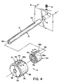
- FIGURE 4 is an exploded pictorial view illustrating the mounting of a single force unit onto a fixed structure as the initial step in constructing the embodiment of the invention illustrated in FIGURES 1-3;
- FIGURE 5 is a pictorial view of the second embodiment of the present invention wherein the force units are connected in series;
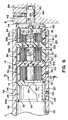
- FIGURE 6 is an enlarged cross-sectional view taken along line 6-6 of FIGURE 5;
- FIGURE 6A is a view similar to FIGURE 6 with the number of force units changed in accordance with the invention;
- FIGURE 7 is an enlarged cross-sectional view taken generally along line 7-7 of FIGURE 6; and,
- FIGURE 8 is an exploded view illustrating the mounting of the first force unit in the embodiment of the invention illustrated in FIGURES 5-7.
- In FIGURES 1-4, device A is constructed in accordance with the present invention for creating rotational biasing between fixed structure B, which is in practice an automobile sidewall of a cargo area and a roller tube C of a security shade used to cover the cargo area. Device A is used to create a rotational biasing force to wind a security shade onto roller tube C as the tube is rotated counterclockwise by using parallel torsion springs, as shown in FIGURE 3. The center, axially extending fixed member of device A is
shaft 10 having atransverse slot 12 with anopen end 12a and a closedend 12b.Opening 14 in fixed side mounting structure B receives the end ofshaft 12 which is secured with respect to structure B by anappropriate set screw 16. Ontoshaft 12 is mounted a plurality offorce units force unit unit 20 will be described and this description will apply equally to the other units. The number for parts of the units are the same.Support cup 30 has a forwardly facing counter bore 32 and a rearwardly extendingboss 34. These cylindrical components match each other so thatboss 34 fits intobore 32 as best shown in FIGURE 2 for aligning a number of force units onshaft 10 and inside tube C. Generallyflat surface 40 defines acavity intersecting slot 42, which slot extends from the boss end ofcup 30 toward its counter bore end.Slot 42 hasaccess end 42a. In this manner,slot 42 receives one end oftorsion spring 50 so the torsion spring is inserted intospring cavity 36 of cup orhousing 30.Torsion spring 50 is formed from a flat spring steel metal with afirst end 52 formed into a straight portion for insertion intoslot 12 ofshaft 10 fromend 12a. Before that assembly takes place,second end 54 ofspring 50 having atab 56 with a radially extendingstraight portion 56a is fitting intoslot 42. Abent retainer 56b oftab 56 fits into the outer recess cavity caused byflat surface 40.Torsion spring 50 is first placed into thecavity 36 of cup orhousing 30 by attaching itssecond end 54 attab 56 onto the spring housing, as best shown in FIGURES 3 and 4. Then, forceunit 20 is mounted onto fixedshaft 10 by slidingstraight end 52 ontoslot 12 fromend 12a. The plurality of force units are assembled in parallel by first mountingtorsion spring 50 intocup 30.Retainer 56b has a width a generally matching and slightly smaller than width b offlat surface 40. Thus,spring 50 is inserted into and retained onhousing 30. Thereafter, the force unit is mounted in parallel onshaft 10 by insertingstraight portion 52 inslot 12. Each end of tube C includesend housing portion 60 with an innercylindrical surface 66. Support cups 30 have outercylindrical surfaces 38 slightly less in diameter thansurface 66 sounits housing portion 60. - As illustrated in FIGURE 4, the first assembly step for the parallel spring embodiment involves placing the
torsion spring 50 offirst force unit 20 into the cup orhousing 30.Tab 56 slides throughaccess end 42a ofslot 42 until the tab is captured inflat portion 40 sotorsion spring 50 has itssecond end 54 secured tohousing 30. Then, forceunit 20 is slipped ontoshaft 10 with flatfirst end 52 sliding intoslot 12 of the shaft. The fixed shaft protrudes outwardly throughopening 39 ofhousing 30 for receivingnext force unit 22 having itstorsion spring 50 already assembled into thenext cup 30. Additionalparallel force units shaft 10. This is accomplished in the same manner. With the four parallel force units in place, the units are then slid into tube C and locked onto the tube byset screws 64 in threadedopenings 62. In FIGURE 2, four force units are affixed to tube C so that the total biasing force is the summation of the torsion forces in the four separate units. In practice, each unit has the same coefficient of torsion force. First end 52 of each spring inparallel force units shaft 10. Second ends 54 of the torsion springs are connected to roller tube C by way ofhousing 30 and setscrew 64.Opening 39 has a diameter greater thanshaft 10 so thatcup 30 can easily rotate on the shaft through the parallel configured torsion springs as shown in FIGURES 1-4. The basic feature of the present invention is illustrated in FIGURE 2A where only threeparallel force units Cup 30 is only a mounting member and not an enclosure or housing. - The preferred embodiment of the invention does not use the parallel connected force units as shown in FIGURES 1-4. To the contrary, the preferred implementation is device A' shown in FIGURES 5-8 uses a plurality of series connected torsion springs. This concept allows adjustment of the rotational angle during the unwinding of the shade. The actual torsion spring of device A' is essentially the same as the previously described
torsion spring 50 used in the parallel spring version of the invention. In this second version,force units terminal connector unit 106 connecting the stack of force units ontoend housing 60. Since series connectedforce units connector unit 106.Torsion spring 50 is used inseries units cup 110. This same cup is used for fastener orconnector unit 106.Cup 110 includes acounter bore 112 andbus 114 which fit together for aligning the units about the same axis.Opening 116 receives thenose 134 of an adjacent slottedshaft 132 after the various units have been assembled in series.Cup 110 hascentral cavity 118 for receiving torsional springs 50 and an outercylindrical surface 120. From one end ofcup 30 there is a mountingshaft 130 having aslot 132 and terminal smallcylindrical nose 134. This nose fits into opening 116 of the prior force unit.Nose 134 rotates inopening 116. As in the first embodiment,cup 110 has outerflat surface 124 with aradial slot 126 having anaccess end 126a sospring 50 can be assembled onto unit 100 (102, 104) bytab 56 fitting intoslot 126, as best illustrated in FIGURE 8. Afterspring 50 is assembled ontohousing 110 ofunit 100,shaft 130 is inserted into opening 140 of fixed structure B. As shown in FIGURES 6 and 8, setscrew 142 then locks thefirst cup 110 onto structure B. The structure offorce unit 100 is shown in FIGURE 8. This same structure is used forforce units reduction connector unit 106 merely employs aspring cup 110 having a forwardly extendingslot 130 with anose 134 extending into opening 116 of the bottom portion offorce unit 104. First end 52 of the three torsion springs are received inslot 132 of thesuccessive cups 110, as shown in FIGURES 6 and 7. Thus,units empty cup 110 comprising theconnector unit 106. This cup is affixed to endhousing 60 byset screw 64. The rotational angle is the sum of the angle of each spring unit.Outer surfaces 120 ofunits cylindrical surface 66 ofend housing 60 of roller tube C. Force is transmitted from structure B by way of series connectedtab 56 tofirst end 52 of the first torsion spring and then from that end totab 56 and then end 52 of the next torsion spring end ofunit 102. From there, force is exerted betweentab 56 and end 52 ofunit 104. From there, force is exerted throughconnector unit 106 directly to roller tube C. Thus, the same spring receptacle or cup is used for all force creating units. At the last unit, for cost reasons, the same cup structure is used to transmit force fromend 52 of the last torsion spring directly to roller tube C. Other structures could be used for the terminal connector unit so long as the force units are connected in series and have a total angular movement equaling the summation of the torsion forces of the series connected force units. - The embodiment of the invention shown in FIGURES 1-4 connects the torsion springs in parallel. Preferred embodiments of the invention shown in FIGURES 5-8 use essentially the same type of structures, but are slightly modified so that the housing of one unit is rotatable with respect to the housing of the adjacent units. An advantage of the structure shown in FIGURES 5-8 is illustrated in FIGURE 6A. To reduce the total angle, only two series connected
force units - The first embodiment of the invention involves connecting torsion springs in parallel. The second and preferred embodiment involves connecting the torsion springs in series. The number of springs in each of these units can be varied so that a standard force unit is manufactured and the amount of torsional force or angular rotation is adjusted by the number of force units assembled into the device for creating the angular biasing force.
Claims (33)
- A device for creating an angular biasing force for a member, which member is mounted to a fixed structure, said device comprising an element attached to said fixed structure and a plurality of force units each including a torsion spring exerting a biasing force between said structure and said member, wherein said torsion springs each have a first inner end associated with said fixed structure and a second outer end associated with said member so the torsion biasing force of each spring is in a direction from said fixed structure to said member.
- A device as defined in claim 1 wherein said torsion springs are connected from said first end to said second end in series to increase the magnitude of angular rotation.
- A device as defined in claim 1 wherein said torsion springs are connected from said first ends to said second ends in parallel to increase the angular force.
- A device as defined in anyone of the claims 1 to 3 wherein said torsion springs have essentially the same torsion coefficient of elasticity.
- A device as defined in claim 4 wherein said device has a selected number of torsion spring force units to adjust said total angular biasing force.
- A device as defined in claim 2 or 4 wherein said device has a selected number of torsion spring force units to adjust said magnitude.
- A device as defined in claim 3 or 4 wherein said device has a selected number of torsion spring force units to adjust said angular biasing force.
- A device as defined in claim 1 wherein said device has a selected number of torsion spring force units.
- A device as defined in claim 3,4 or 7 wherein said roller tube has an end housing with an inner cylindrical surface and each of said torsion spring force units have a support housing with an outer cylindrical surface slidable in said inner cylindrical surface of said end housing and a fastener to selectively attach said force units to said end housing.
- A device as defined in claim 2, 4 or 7 wherein said roller tube has an end housing with an inner cylindrical surface and each of said torsion spring force units have a support housing with an outer cylindrical surface slidable in said inner cylindrical surface of said end housing and a fastener to attach the last of said force units to said end housing.
- A device as defined in anyone of the claims 1 to 10 wherein said member is an elongated member.
- A device as defined in claim 11 wherein said elongated member is a roller tube for a security shade and said biasing force is in a direction winding said shade on said roller.
- A device as defined in anyone of the claims 1 to 12 wherein said number is a roller tube of a security shade, which roller tube is mounted to a fixed structure of a vehicle, said device comprising an element attached to said fixed structure of the vehicle and a plurality of force units each including a torsion spring exerting a biasing force between said structure and said roller tube, wherein said torsion springs each have a first inner end associated with said fixed structure and a second outer end associated with said roller tube so the torsion biasing force of each spring is in a direction from said fixed structure to said roller tube.
- A device as defined in claim 13 wherein said torsion springs are connected from said first end to said second end in series to increase the magnitude of angular rotation.
- A device as defined in claim 13 wherein said torsion springs are connected from said first ends to said second ends in parallel to increase the angular force.
- A device as defined in anyone of the claims 12 to 15 wherein said device has a selected number of torsion spring force units.
- A device as defined in claim12, 15 or 16 wherein said roller tube has an end housing with an inner cylindrical surface and each of said torsion spring force units have a support housing with an outer cylindrical surface slidable in said inner cylindrical surface of said end housing and a fastener to selectively attach said force units to said end housing.
- A device as defined in anyone of the claims 12 to 14 wherein said roller tube has an end housing with an inner cylindrical surface and each of said torsion spring force units have a support housing with an outer cylindrical surface slidable in said inner cylindrical surface of said end housing and a fastener to attach the last of said force units to said end housing.
- A device for creating an angular biasing force between a fixed structure and an elongated member mounted with respect to said structure for rotation about an axis generally perpendicular to said structure, said device comprising: a plurality of parallel connected torsion spring, each formed from convolutions of flat spring metal coiled concentrically around said axis, each of said torsion springs having a first end fixed to said structure and a second end connected to said member.
- A device as defined in claim 19 wherein said torsion springs have essentially the same torsion coefficient of elasticity.
- A device as defined in claim 19 or 20 wherein said device has more than two torsion springs.
- A device as defined in anyone of the claims 19 to 21 wherein each of said coiled torsion springs each comprises an outer housing with a radial cavity to capture said second end and outer area attached to elongated member.
- A device as defined in anyone of the claims 19 to 22 or 12 including an elongated shaft fixed to said structure and extending along said axis and a slot in said shaft for capturing said first ends of each of said torsion springs.
- A device as defined in anyone of the claims 19 to 23 wherein said elongated member is a roller tube for a security shade and said biasing force is in a direction winding said shade on said roller.
- A device as defined in anyone of the claims 22 to 24 wherein said radial cavity includes a radial slot.
- A device for creating an angular biasing force between a fixed structure and an elongated member mounted with respect to said fixed structure for rotation about an axis generally perpendicular to said structure, said device comprising: a plurality of torsion springs concentric with said axis and connected in series from a first torsion spring to a last torsion spring, each of said torsion springs formed of flat spring metal coiled concentrically around said axis with a first inner convolution end and a second outer convolution end, a mounting cup for each of said torsion springs, each of said cups having a spring cavity defined by a cylindrical wall concentric with said axis and a slotted shaft extending from said cavity and concentric with said axis, said cylindrical wall having a contoured opening to capture said second end of one of said torsion springs, said slotted shaft adapted to capture the first end of a next series spring, with said member only connected to said first end of said last torsion spring and said mounting cup of said first spring connected to said fixed structure.
- A device as defined in claim 26 wherein said torsion springs have essentially the same torsion coefficient of elasticity.
- A device as defined in claim 26 or 27 wherein said device has more than two torsion springs.
- A device as defined in anyone of the claims 26 to 28 wherein said elongated member is a roller tube for a security shade and said biasing force is in a direction winding said shade on said roller.
- A device as defined in anyone of the claims 26 to 29 or 24 wherein said slotted shaft of said mounting cup of said first torsion spring is adapted to be attached to said fixed structure.
- A subassembly for a series torsion spring motor, said subassembly comprising a mounting cup having a spring cavity defined by a cylindrical wall and a slotted shaft extending from said cavity and concentric with said wall, a torsion spring formed of flat spring metal with an axis concentric to said shaft, a second outer convolution end connected to said wall and a first inner convolution end adapted to be connected to a slotted shaft of a mounting cup of an adjacent, concentric subassembly.
- A subassembly as defined in claim 31 wherein said second end of said torsion spring is releasably connected to said wall of said mounting cup.
- A subassembly as defined in claim 31 or 32 wherein said first end is releasably connectable to said slotted shaft of said adjacent subassembly.
Applications Claiming Priority (1)
| Application Number | Priority Date | Filing Date | Title |
|---|---|---|---|
| US11/023,180 US7717156B2 (en) | 2004-12-28 | 2004-12-28 | Device for creating an adjustable angular force |
Publications (2)
| Publication Number | Publication Date |
|---|---|
| EP1676748A1 true EP1676748A1 (en) | 2006-07-05 |
| EP1676748B1 EP1676748B1 (en) | 2007-10-31 |
Family
ID=36168476
Family Applications (1)
| Application Number | Title | Priority Date | Filing Date |
|---|---|---|---|
| EP05028473A Active EP1676748B1 (en) | 2004-12-28 | 2005-12-24 | A device for creating an angular biasing force |
Country Status (5)
| Country | Link |
|---|---|
| US (2) | US7717156B2 (en) |
| EP (1) | EP1676748B1 (en) |
| JP (1) | JP4234133B2 (en) |
| AT (1) | ATE376944T1 (en) |
| DE (1) | DE602005003098T2 (en) |
Cited By (3)
| Publication number | Priority date | Publication date | Assignee | Title |
|---|---|---|---|---|
| US7717156B2 (en) | 2004-12-28 | 2010-05-18 | Barnes Group Inc. | Device for creating an adjustable angular force |
| WO2014139777A1 (en) * | 2013-03-14 | 2014-09-18 | Webasto SE | Roller blind arrangement with winding shaft |
| FR3055855A1 (en) * | 2016-09-09 | 2018-03-16 | Cera Aps | AUTOMOTIVE VEHICLE LUGGAGE COMPARTMENT REPAIR SYSTEM |
Families Citing this family (23)
| Publication number | Priority date | Publication date | Assignee | Title |
|---|---|---|---|---|
| GB0700967D0 (en) | 2007-01-18 | 2007-02-28 | Louver Life Ltd | Window coverings |
| CA2710790C (en) * | 2008-01-04 | 2016-02-02 | Hunter Douglas Industries B.V. | Operating unit for architectural coverings |
| CN101676766B (en) * | 2008-09-16 | 2011-07-27 | 鸿富锦精密工业(深圳)有限公司 | Protective device of electronic equipment screen |
| US20100122780A1 (en) * | 2008-11-18 | 2010-05-20 | Zipshade Industrial (B.V.I.) Corp. | Screen rolling device |
| US8205924B2 (en) * | 2009-12-28 | 2012-06-26 | Kawasaki Jukogyo Kabushiki Kaisha | Pick-up style utility vehicle with expandable cargo bed |
| US9249623B2 (en) | 2010-02-23 | 2016-02-02 | Qmotion Incorporated | Low-power architectural covering |
| US8575872B2 (en) | 2010-02-23 | 2013-11-05 | Homerun Holdings Corporation | High efficiency roller shade and method for setting artificial stops |
| US8659246B2 (en) | 2010-02-23 | 2014-02-25 | Homerun Holdings Corporation | High efficiency roller shade |
| US9194179B2 (en) | 2010-02-23 | 2015-11-24 | Qmotion Incorporated | Motorized shade with the transmission wire passing through the support shaft |
| US8800633B2 (en) * | 2010-05-04 | 2014-08-12 | Qmotion Incorporated | Anti-reversible power spring apparatus and method |
| US8807196B2 (en) * | 2010-05-04 | 2014-08-19 | Qmotion Incorporated | Modular anti-reversible power spring apparatus and method |
| WO2013033014A1 (en) | 2011-08-26 | 2013-03-07 | Hunter Douglas Inc. | Cordless retractable roller shade for window coverings |
| US10934773B2 (en) | 2012-06-13 | 2021-03-02 | Somfy Activites Sa | Motorized manoeuvring device intended to manoeuvre a moving windable fabric screen of a window or projection screen cover device |
| FR2992142B1 (en) * | 2012-06-13 | 2014-07-11 | Somfy Sas | ELEMENT FOR SUPPORTING A BATTERY IN A WINDOW TUBE OF A DOMOTIC SCREEN |
| FR2992114B1 (en) | 2012-06-13 | 2016-08-19 | Somfy Sas | MOTORIZED MANEUVER DEVICE FOR MANEUVERING A MOBILE SCREEN WITH A WINDABLE CANVAS OF A WINDOW COVER OR PROJECTION SCREEN DEVICE. |
| US9207058B2 (en) * | 2012-09-19 | 2015-12-08 | Stanley Black & Decker, Inc. | Measuring tape rule device |
| US9206634B1 (en) * | 2013-03-15 | 2015-12-08 | Overhead Door Corporation | Counterbalance system for vertical acting doors |
| EP2971422B1 (en) * | 2013-03-15 | 2019-09-11 | Hunter Douglas Inc. | Position lock for roller supported architectural coverings |
| US9103157B2 (en) * | 2013-04-13 | 2015-08-11 | Qmotion Incorporated | Spring counterbalance apparatus and method |
| WO2016077373A1 (en) * | 2014-11-10 | 2016-05-19 | Hunter Douglas Inc. | Covering for an architectural opening including multiple stage spring assembly |
| TWI665379B (en) * | 2017-11-27 | 2019-07-11 | 協駿股份有限公司 | Detachable rope reel for non-exposed drawstring curtains |
| CN107989537A (en) * | 2017-12-22 | 2018-05-04 | 深圳市万氏窗饰有限公司 | A kind of cord draw off gear of flexibility variable force |
| EP4176154A1 (en) | 2020-07-02 | 2023-05-10 | Springs Window Fashions, LLC | Roller shade assembly |
Citations (6)
| Publication number | Priority date | Publication date | Assignee | Title |
|---|---|---|---|---|
| US1392918A (en) * | 1919-11-08 | 1921-10-11 | John M Cornell | Construction of rolling doors, shutters, and curtains |
| DE509237C (en) * | 1930-10-06 | L Invulnerabiln Soc | Winding roller for shutters | |
| FR2621069A1 (en) * | 1987-09-25 | 1989-03-31 | Somaco | Roller shutter door safety device |
| EP0446049A2 (en) * | 1990-03-07 | 1991-09-11 | Rotalac Plastics Limited | Improved roller shutter assembly |
| US5284199A (en) * | 1989-10-23 | 1994-02-08 | Finch Harry E | Panel construction for a wall or roll-up door system |
| EP1251021A1 (en) * | 2001-04-18 | 2002-10-23 | Centre d'Etude et de Recherche pour l'Automobile ( CERA) | Curtain with coiled spring |
Family Cites Families (22)
| Publication number | Priority date | Publication date | Assignee | Title |
|---|---|---|---|---|
| US270469A (en) * | 1883-01-09 | Window-screen | ||
| US102409A (en) * | 1870-04-26 | Improved curtain-fixture | ||
| US1235092A (en) * | 1913-01-25 | 1917-07-31 | Hayward Co | Automatic cable-take-up device. |
| US1266716A (en) * | 1916-08-18 | 1918-05-21 | Henry Schuerhoff | Fly-screen. |
| US1941880A (en) * | 1931-09-21 | 1934-01-02 | Charles I Earll | Reel |
| US2098016A (en) * | 1936-11-12 | 1937-11-02 | Adlake Co | Curtain construction |
| US2485385A (en) * | 1945-08-13 | 1949-10-18 | Rodger F Becker | Reel |
| US2696250A (en) * | 1953-08-28 | 1954-12-07 | Michelman Nathan | Rolling door |
| US3929210A (en) * | 1974-05-28 | 1975-12-30 | Vacuum Cleaner Corp Of America | Retractable cord reel |
| US4139231A (en) * | 1978-05-08 | 1979-02-13 | Irvin Industries Inc. | Automobile rear compartment cover |
| US5201897A (en) * | 1992-01-30 | 1993-04-13 | Whitling Roll-Up Door Mfg. Corp. | Spring balancer for a roll-up door |
| US5275223A (en) * | 1992-02-28 | 1994-01-04 | Sebastian Magro | Support roller provided with roll-up mechanism for rolling doors, gates and the like |
| US5271446A (en) * | 1993-03-02 | 1993-12-21 | Hwang Chyi Ming | Multi-purpose automatically rewindable sun-shade |
| US5464052A (en) * | 1993-11-08 | 1995-11-07 | Takata, Inc. | Security shade with a motor spring subassembly |
| JP3650838B2 (en) | 1995-12-28 | 2005-05-25 | 日本発条株式会社 | Blind winder for automobile |
| DE69618184T2 (en) * | 1996-07-23 | 2002-07-11 | Pei Protezioni Elaborazioni | A rolling device for rolling up and tensioning a flexible element such as a web of material, a roller shutter or the like, in particular for protecting machines |
| US5934354A (en) * | 1997-10-23 | 1999-08-10 | Irvin Automotive Products, Inc. | Security shade support assembly |
| ATE301235T1 (en) * | 1997-11-04 | 2005-08-15 | Toti Andrew J | FLAT SPRING DRIVE AND WINDOW COVER |
| US6131643A (en) * | 1998-11-17 | 2000-10-17 | New Century Sci & Tech, Inc. | Sun shield device for parked automobile |
| US6012506A (en) * | 1999-01-04 | 2000-01-11 | Industrial Technology Research Institute | Venetian blind provided with slat-lifting mechanism having constant force equilibrium |
| DE19927384C1 (en) * | 1999-06-16 | 2000-12-07 | Bos Gmbh | Separating device with variable retraction force |
| US7717156B2 (en) | 2004-12-28 | 2010-05-18 | Barnes Group Inc. | Device for creating an adjustable angular force |
-
2004
- 2004-12-28 US US11/023,180 patent/US7717156B2/en active Active
-
2005
- 2005-12-24 AT AT05028473T patent/ATE376944T1/en not_active IP Right Cessation
- 2005-12-24 EP EP05028473A patent/EP1676748B1/en active Active
- 2005-12-24 DE DE602005003098T patent/DE602005003098T2/en not_active Expired - Fee Related
- 2005-12-26 JP JP2005371912A patent/JP4234133B2/en not_active Expired - Fee Related
-
2008
- 2008-08-05 US US12/186,084 patent/US8567476B2/en active Active
Patent Citations (6)
| Publication number | Priority date | Publication date | Assignee | Title |
|---|---|---|---|---|
| DE509237C (en) * | 1930-10-06 | L Invulnerabiln Soc | Winding roller for shutters | |
| US1392918A (en) * | 1919-11-08 | 1921-10-11 | John M Cornell | Construction of rolling doors, shutters, and curtains |
| FR2621069A1 (en) * | 1987-09-25 | 1989-03-31 | Somaco | Roller shutter door safety device |
| US5284199A (en) * | 1989-10-23 | 1994-02-08 | Finch Harry E | Panel construction for a wall or roll-up door system |
| EP0446049A2 (en) * | 1990-03-07 | 1991-09-11 | Rotalac Plastics Limited | Improved roller shutter assembly |
| EP1251021A1 (en) * | 2001-04-18 | 2002-10-23 | Centre d'Etude et de Recherche pour l'Automobile ( CERA) | Curtain with coiled spring |
Cited By (4)
| Publication number | Priority date | Publication date | Assignee | Title |
|---|---|---|---|---|
| US7717156B2 (en) | 2004-12-28 | 2010-05-18 | Barnes Group Inc. | Device for creating an adjustable angular force |
| US8567476B2 (en) | 2004-12-28 | 2013-10-29 | Barnes Group Inc. | Device for creating an angular biasing force |
| WO2014139777A1 (en) * | 2013-03-14 | 2014-09-18 | Webasto SE | Roller blind arrangement with winding shaft |
| FR3055855A1 (en) * | 2016-09-09 | 2018-03-16 | Cera Aps | AUTOMOTIVE VEHICLE LUGGAGE COMPARTMENT REPAIR SYSTEM |
Also Published As
| Publication number | Publication date |
|---|---|
| US20080289777A1 (en) | 2008-11-27 |
| JP2006188217A (en) | 2006-07-20 |
| JP4234133B2 (en) | 2009-03-04 |
| US20060137837A1 (en) | 2006-06-29 |
| US7717156B2 (en) | 2010-05-18 |
| ATE376944T1 (en) | 2007-11-15 |
| EP1676748B1 (en) | 2007-10-31 |
| DE602005003098D1 (en) | 2007-12-13 |
| DE602005003098T2 (en) | 2008-08-14 |
| US8567476B2 (en) | 2013-10-29 |
Similar Documents
| Publication | Publication Date | Title |
|---|---|---|
| EP1676748B1 (en) | A device for creating an angular biasing force | |
| US4668001A (en) | Securing device for a baggage cover sheet winder | |
| EP0652136B1 (en) | Security cover with a spring motor subassembly | |
| JP4467893B2 (en) | Pre-assembled window shade parts | |
| US4482137A (en) | Compartment shade | |
| US20190176704A1 (en) | Folding joint for rear view display device | |
| US20020021509A1 (en) | Extendable mirror with improved detent | |
| EP2397368A1 (en) | Cargo net device | |
| MXPA01010188A (en) | An extendable and pivotal rearview mirror assembly. | |
| US6871383B2 (en) | Hinge device | |
| US20130147225A1 (en) | Retractable rod ends for liftgate mounted cargo shade | |
| EP0890478A2 (en) | Compressible pocket for cargo shade attachment | |
| EP2397369A1 (en) | Cargo net device | |
| US8770256B2 (en) | Fixed motor spring shade | |
| JP4848418B2 (en) | Winding blind system with final position braking | |
| US11794650B2 (en) | Folding joint for rear view display device | |
| US10974650B2 (en) | Rearview device mount and attachment method | |
| US20080216970A1 (en) | Sunshade assembly suitable for an arcuate window | |
| US7549457B2 (en) | Silicone shade | |
| WO2010046133A2 (en) | Adjustable cup dispenser | |
| US20100011536A1 (en) | Hinge mechanism for foldable electronic device | |
| CN101228987A (en) | Handle device for portable storage body | |
| US20070283533A1 (en) | Hinge assembly | |
| US20240123902A1 (en) | Folding joint for rear view display device | |
| EP3964396A1 (en) | Folding joint for rear view display device |
Legal Events
| Date | Code | Title | Description |
|---|---|---|---|
| PUAI | Public reference made under article 153(3) epc to a published international application that has entered the european phase |
Free format text: ORIGINAL CODE: 0009012 |
|
| AK | Designated contracting states |
Kind code of ref document: A1 Designated state(s): AT BE BG CH CY CZ DE DK EE ES FI FR GB GR HU IE IS IT LI LT LU LV MC NL PL PT RO SE SI SK TR |
|
| AX | Request for extension of the european patent |
Extension state: AL BA HR MK YU |
|
| 17P | Request for examination filed |
Effective date: 20070105 |
|
| AKX | Designation fees paid |
Designated state(s): AT BE BG CH CY CZ DE DK EE ES FI FR GB GR HU IE IS IT LI LT LU LV MC NL PL PT RO SE SI SK TR |
|
| GRAP | Despatch of communication of intention to grant a patent |
Free format text: ORIGINAL CODE: EPIDOSNIGR1 |
|
| GRAS | Grant fee paid |
Free format text: ORIGINAL CODE: EPIDOSNIGR3 |
|
| GRAA | (expected) grant |
Free format text: ORIGINAL CODE: 0009210 |
|
| AK | Designated contracting states |
Kind code of ref document: B1 Designated state(s): AT BE BG CH CY CZ DE DK EE ES FI FR GB GR HU IE IS IT LI LT LU LV MC NL PL PT RO SE SI SK TR |
|
| REG | Reference to a national code |
Ref country code: GB Ref legal event code: FG4D |
|
| RIN2 | Information on inventor provided after grant (corrected) |
Inventor name: COSTELLO, PHILIP G. Inventor name: ROGERS, CHARLES K. Inventor name: RABABEH, MEHIEDDINE Inventor name: STEBBEDS, RONALD D., JR. |
|
| REG | Reference to a national code |
Ref country code: IE Ref legal event code: FG4D |
|
| REG | Reference to a national code |
Ref country code: CH Ref legal event code: EP |
|
| REF | Corresponds to: |
Ref document number: 602005003098 Country of ref document: DE Date of ref document: 20071213 Kind code of ref document: P |
|
| REG | Reference to a national code |
Ref country code: SE Ref legal event code: TRGR |
|
| NLV1 | Nl: lapsed or annulled due to failure to fulfill the requirements of art. 29p and 29m of the patents act | ||
| PG25 | Lapsed in a contracting state [announced via postgrant information from national office to epo] |
Ref country code: LI Free format text: LAPSE BECAUSE OF FAILURE TO SUBMIT A TRANSLATION OF THE DESCRIPTION OR TO PAY THE FEE WITHIN THE PRESCRIBED TIME-LIMIT Effective date: 20071031 Ref country code: CH Free format text: LAPSE BECAUSE OF FAILURE TO SUBMIT A TRANSLATION OF THE DESCRIPTION OR TO PAY THE FEE WITHIN THE PRESCRIBED TIME-LIMIT Effective date: 20071031 Ref country code: ES Free format text: LAPSE BECAUSE OF FAILURE TO SUBMIT A TRANSLATION OF THE DESCRIPTION OR TO PAY THE FEE WITHIN THE PRESCRIBED TIME-LIMIT Effective date: 20080211 Ref country code: NL Free format text: LAPSE BECAUSE OF FAILURE TO SUBMIT A TRANSLATION OF THE DESCRIPTION OR TO PAY THE FEE WITHIN THE PRESCRIBED TIME-LIMIT Effective date: 20071031 |
|
| REG | Reference to a national code |
Ref country code: CH Ref legal event code: PL |
|
| ET | Fr: translation filed | ||
| PG25 | Lapsed in a contracting state [announced via postgrant information from national office to epo] |
Ref country code: PT Free format text: LAPSE BECAUSE OF FAILURE TO SUBMIT A TRANSLATION OF THE DESCRIPTION OR TO PAY THE FEE WITHIN THE PRESCRIBED TIME-LIMIT Effective date: 20080331 Ref country code: LV Free format text: LAPSE BECAUSE OF FAILURE TO SUBMIT A TRANSLATION OF THE DESCRIPTION OR TO PAY THE FEE WITHIN THE PRESCRIBED TIME-LIMIT Effective date: 20071031 Ref country code: PL Free format text: LAPSE BECAUSE OF FAILURE TO SUBMIT A TRANSLATION OF THE DESCRIPTION OR TO PAY THE FEE WITHIN THE PRESCRIBED TIME-LIMIT Effective date: 20071031 Ref country code: IS Free format text: LAPSE BECAUSE OF FAILURE TO SUBMIT A TRANSLATION OF THE DESCRIPTION OR TO PAY THE FEE WITHIN THE PRESCRIBED TIME-LIMIT Effective date: 20080229 Ref country code: LT Free format text: LAPSE BECAUSE OF FAILURE TO SUBMIT A TRANSLATION OF THE DESCRIPTION OR TO PAY THE FEE WITHIN THE PRESCRIBED TIME-LIMIT Effective date: 20071031 Ref country code: SI Free format text: LAPSE BECAUSE OF FAILURE TO SUBMIT A TRANSLATION OF THE DESCRIPTION OR TO PAY THE FEE WITHIN THE PRESCRIBED TIME-LIMIT Effective date: 20071031 Ref country code: BG Free format text: LAPSE BECAUSE OF FAILURE TO SUBMIT A TRANSLATION OF THE DESCRIPTION OR TO PAY THE FEE WITHIN THE PRESCRIBED TIME-LIMIT Effective date: 20080131 |
|
| PG25 | Lapsed in a contracting state [announced via postgrant information from national office to epo] |
Ref country code: AT Free format text: LAPSE BECAUSE OF FAILURE TO SUBMIT A TRANSLATION OF THE DESCRIPTION OR TO PAY THE FEE WITHIN THE PRESCRIBED TIME-LIMIT Effective date: 20071031 |
|
| PG25 | Lapsed in a contracting state [announced via postgrant information from national office to epo] |
Ref country code: DK Free format text: LAPSE BECAUSE OF FAILURE TO SUBMIT A TRANSLATION OF THE DESCRIPTION OR TO PAY THE FEE WITHIN THE PRESCRIBED TIME-LIMIT Effective date: 20071031 Ref country code: CZ Free format text: LAPSE BECAUSE OF FAILURE TO SUBMIT A TRANSLATION OF THE DESCRIPTION OR TO PAY THE FEE WITHIN THE PRESCRIBED TIME-LIMIT Effective date: 20071031 Ref country code: MC Free format text: LAPSE BECAUSE OF NON-PAYMENT OF DUE FEES Effective date: 20071231 |
|
| PG25 | Lapsed in a contracting state [announced via postgrant information from national office to epo] |
Ref country code: BE Free format text: LAPSE BECAUSE OF FAILURE TO SUBMIT A TRANSLATION OF THE DESCRIPTION OR TO PAY THE FEE WITHIN THE PRESCRIBED TIME-LIMIT Effective date: 20071031 Ref country code: RO Free format text: LAPSE BECAUSE OF FAILURE TO SUBMIT A TRANSLATION OF THE DESCRIPTION OR TO PAY THE FEE WITHIN THE PRESCRIBED TIME-LIMIT Effective date: 20071031 Ref country code: SK Free format text: LAPSE BECAUSE OF FAILURE TO SUBMIT A TRANSLATION OF THE DESCRIPTION OR TO PAY THE FEE WITHIN THE PRESCRIBED TIME-LIMIT Effective date: 20071031 |
|
| PLBE | No opposition filed within time limit |
Free format text: ORIGINAL CODE: 0009261 |
|
| STAA | Information on the status of an ep patent application or granted ep patent |
Free format text: STATUS: NO OPPOSITION FILED WITHIN TIME LIMIT |
|
| 26N | No opposition filed |
Effective date: 20080801 |
|
| PG25 | Lapsed in a contracting state [announced via postgrant information from national office to epo] |
Ref country code: IE Free format text: LAPSE BECAUSE OF NON-PAYMENT OF DUE FEES Effective date: 20071224 |
|
| PG25 | Lapsed in a contracting state [announced via postgrant information from national office to epo] |
Ref country code: EE Free format text: LAPSE BECAUSE OF FAILURE TO SUBMIT A TRANSLATION OF THE DESCRIPTION OR TO PAY THE FEE WITHIN THE PRESCRIBED TIME-LIMIT Effective date: 20071031 Ref country code: GR Free format text: LAPSE BECAUSE OF FAILURE TO SUBMIT A TRANSLATION OF THE DESCRIPTION OR TO PAY THE FEE WITHIN THE PRESCRIBED TIME-LIMIT Effective date: 20080201 |
|
| PG25 | Lapsed in a contracting state [announced via postgrant information from national office to epo] |
Ref country code: FI Free format text: LAPSE BECAUSE OF FAILURE TO SUBMIT A TRANSLATION OF THE DESCRIPTION OR TO PAY THE FEE WITHIN THE PRESCRIBED TIME-LIMIT Effective date: 20071031 |
|
| PGFP | Annual fee paid to national office [announced via postgrant information from national office to epo] |
Ref country code: SE Payment date: 20081208 Year of fee payment: 4 |
|
| PGFP | Annual fee paid to national office [announced via postgrant information from national office to epo] |
Ref country code: FR Payment date: 20081205 Year of fee payment: 4 |
|
| PGFP | Annual fee paid to national office [announced via postgrant information from national office to epo] |
Ref country code: DE Payment date: 20081230 Year of fee payment: 4 |
|
| PG25 | Lapsed in a contracting state [announced via postgrant information from national office to epo] |
Ref country code: CY Free format text: LAPSE BECAUSE OF FAILURE TO SUBMIT A TRANSLATION OF THE DESCRIPTION OR TO PAY THE FEE WITHIN THE PRESCRIBED TIME-LIMIT Effective date: 20071031 |
|
| PG25 | Lapsed in a contracting state [announced via postgrant information from national office to epo] |
Ref country code: LU Free format text: LAPSE BECAUSE OF NON-PAYMENT OF DUE FEES Effective date: 20071224 |
|
| PG25 | Lapsed in a contracting state [announced via postgrant information from national office to epo] |
Ref country code: HU Free format text: LAPSE BECAUSE OF FAILURE TO SUBMIT A TRANSLATION OF THE DESCRIPTION OR TO PAY THE FEE WITHIN THE PRESCRIBED TIME-LIMIT Effective date: 20080501 Ref country code: TR Free format text: LAPSE BECAUSE OF FAILURE TO SUBMIT A TRANSLATION OF THE DESCRIPTION OR TO PAY THE FEE WITHIN THE PRESCRIBED TIME-LIMIT Effective date: 20071031 |
|
| EUG | Se: european patent has lapsed | ||
| GBPC | Gb: european patent ceased through non-payment of renewal fee |
Effective date: 20091224 |
|
| REG | Reference to a national code |
Ref country code: FR Ref legal event code: ST Effective date: 20100831 |
|
| PG25 | Lapsed in a contracting state [announced via postgrant information from national office to epo] |
Ref country code: FR Free format text: LAPSE BECAUSE OF NON-PAYMENT OF DUE FEES Effective date: 20091231 |
|
| PG25 | Lapsed in a contracting state [announced via postgrant information from national office to epo] |
Ref country code: DE Free format text: LAPSE BECAUSE OF NON-PAYMENT OF DUE FEES Effective date: 20100701 |
|
| PG25 | Lapsed in a contracting state [announced via postgrant information from national office to epo] |
Ref country code: GB Free format text: LAPSE BECAUSE OF NON-PAYMENT OF DUE FEES Effective date: 20091224 |
|
| PG25 | Lapsed in a contracting state [announced via postgrant information from national office to epo] |
Ref country code: SE Free format text: LAPSE BECAUSE OF NON-PAYMENT OF DUE FEES Effective date: 20091225 |
|
| PGFP | Annual fee paid to national office [announced via postgrant information from national office to epo] |
Ref country code: IT Payment date: 20081231 Year of fee payment: 4 |