EP1676718A2 - Retractable guide strips of an apparatus for inserting documents into envelopes - Google Patents
Retractable guide strips of an apparatus for inserting documents into envelopes Download PDFInfo
- Publication number
- EP1676718A2 EP1676718A2 EP05078036A EP05078036A EP1676718A2 EP 1676718 A2 EP1676718 A2 EP 1676718A2 EP 05078036 A EP05078036 A EP 05078036A EP 05078036 A EP05078036 A EP 05078036A EP 1676718 A2 EP1676718 A2 EP 1676718A2
- Authority
- EP
- European Patent Office
- Prior art keywords
- transport path
- envelope
- document
- carrier
- guide strips
- Prior art date
- Legal status (The legal status is an assumption and is not a legal conclusion. Google has not performed a legal analysis and makes no representation as to the accuracy of the status listed.)
- Granted
Links
- 238000006073 displacement reaction Methods 0.000 claims description 4
- 239000000969 carrier Substances 0.000 description 24
- 230000037431 insertion Effects 0.000 description 3
- 238000003780 insertion Methods 0.000 description 3
- 230000005540 biological transmission Effects 0.000 description 2
- 230000001419 dependent effect Effects 0.000 description 1
- 230000000694 effects Effects 0.000 description 1
Images

Classifications
-
- B—PERFORMING OPERATIONS; TRANSPORTING
- B43—WRITING OR DRAWING IMPLEMENTS; BUREAU ACCESSORIES
- B43M—BUREAU ACCESSORIES NOT OTHERWISE PROVIDED FOR
- B43M3/00—Devices for inserting documents into envelopes
- B43M3/04—Devices for inserting documents into envelopes automatic
- B43M3/045—Devices for inserting documents into envelopes automatic for envelopes with only one flap
Definitions
- This invention relates to an apparatus for inserting documents into envelopes.
- Such an apparatus is for instance known from U.S. patent 4,888,938 and are typically used in mailrooms where large numbers of documents or sets of documents are each to be inserted in an envelope in order to send these documents to addressees.
- the apparatus according to the example represented in the drawing has a document transport path 1 for transporting documents, of which in this example a specimen 2 is represented in different stages of transport.
- the document transport path 1 according to this example is determined by a guide 3, a pair of opposite transport rollers 4, 5 and a guide 15.
- the envelope transport path 6 passes, according to this example, between on the one hand a set of transport rollers 7 and on the other a guide 8 and a set of flap hold-open rollers 9.
- a holder 10 Connected to the envelope transport path 6 is a holder 10 for receiving and holding an envelope 11 in a stuffing position aligned with the envelope transport path 6.
- the envelope 11 is represented in the drawing in the stuffing position, and, for the purpose of illustration, cutaway on the viewing side. It is noted that within the framework of the present invention, it is also possible to provide that the envelope can reach the stuffing position exclusively or additionally by a route other than along a path 6 with the flap trailing, for instance in opposite direction, with the flap leading.
- the flap hold-open element 9 keeps the flap 12 of the envelope 11 in the stuffing position open.
- the holder 10 also aligns with the document transport path 1 for receiving in an envelope 11 in the stuffing position a document 2 or documents coming from the document transport path 1.
- Guide strips 13, 14 are reciprocable between a retracted position (see Figs. 1, 2 and 4) and a projecting position (see Fig. 3) in which they reach further into the stuffing position than in the retracted position, for guiding a document 2 coming from the document transport path 1 into the envelope 11 in the stuffing position.
- carriers 16 Adjacent the guide 15, carriers 16 reach, via slots between the transport rollers 5, into the document transport path 1 for engagement by documents 2 transported along the document transport path 1.
- the carriers 16 can be carried along by documents 2 transported along the document transport path 1, from a rest position (Figs. 1, 2, 4) to a carried position (Fig. 3).
- the guide strips 13, 14 are coupled with the carriers 16 for displacement from the retracted position to the projecting position in response to the carriers 16 being carried along by a document 2 engaging the carriers 16.
- the carriers 16 also form carrier arms via which the guide strips 14 are suspended pivotably about the centerline of the rollers 5.
- the carriers 16 are coupled with the outer guide strips via a cross bar 17, supporting arms 18, 19 and a bearing 20 about the shaft 21 of the rollers 5.
- the carriers 16 are thus designed as rockers which are pivotable about the shaft 21 of the transport roller 5 of the transport path 1.
- the guide strips 13, 14 serve for moving the neckline 23 of the envelope away from the other wall 22 of the envelope 11, and keeping it so, and for guiding documents 2, to prevent hooking, past the neckline 23 of the envelope 11.
- the inner ones of the guide strips 14 project deep into the envelope 11 parallel or almost parallel to the envelope stuffing position, so that the envelope neckline is reliably opened to its deepest point, while the risk of damage to the envelope 11 is small and the outer ones of the guide strips 13 open the envelope relative far closely along its edges, so that entering document are reliably prevented from clinging to the envelope neckline close to the outer edges of the envelope.
- the guide strips 13, 14 are suspended to a carrier 16 rotatable about an axis parallel to the envelope stuffing position, wherein the outer ones of the guide strips 13 extend from positions at the carrier 16 that are located closer to the axis of rotation of the carrier 16 than the positions from which the inner ones of the guide strips 14 project. In this manner the difference in angels at which the guide strips 13, 14 project into the envelope 11, when in the projecting position is realized in a simple manner.
- the carriers 16 are carried along from the moment when a document 2 advancing along the document transport path 1 reaches the position represented in Figs. 1 and 2. As the leading edge of the document 2 is held against or at least close to the rollers 5 by the guide 15, the carriers 16 are reliably pushed on by the advancing document. However, as soon as the leading edge of the document 2 reaches the downstream end of the guide 15, it gets an opportunity to leave the path of the carriers 16, thereby coming off the carriers.
- the place where the advancement of the carriers 16 by the leading edge 2 of a document 2 terminates is reliably determined by the place in the paths of travel of the carriers 16 where the downstream end of the guide is situated.
- the termination of the carriers being carried along can also be determined in a different manner, for instance in that the carriers are so suspended that, upon being carried along, they leave the transport path at a particular point.
- the transmission of the movement of the carriers 16 to the movement of the guide strips 13, 14 is particularly simple.
- a carrier can operate a clutch which ensures that the strips are driven to the projecting position through rotation of a transport roller.
- the envelope 11 can be discharged in a direction away from the transport rollers 5, 7. If it is desired to discharge the envelope 11 between the transport rollers 5, 7, it may for instance be provided that through rotation of the transport roller 5 against the input sense, the supporting arms 16, 18, 19 are carried along, so that the strips swing out of the discharge path of the envelope 11. According to this example, the retraction of the strips to the retracted position is driven by springs 24 engaging the cross bar 17.
Landscapes
- Feeding Of Articles By Means Other Than Belts Or Rollers (AREA)
- Packaging Of Special Articles (AREA)
- Registering Or Overturning Sheets (AREA)
- Separation, Sorting, Adjustment, Or Bending Of Sheets To Be Conveyed (AREA)
- Auxiliary Devices For And Details Of Packaging Control (AREA)
Abstract
Description
- This invention relates to an apparatus for inserting documents into envelopes. Such an apparatus is for instance known from U.S. patent 4,888,938 and are typically used in mailrooms where large numbers of documents or sets of documents are each to be inserted in an envelope in order to send these documents to addressees.
- However, also in small organizations that send relatively small numbers of documents, and where the documents to be sent are for a considerable part processed by hand also when being prepared prior to insertion, mechanized insertion could lead to considerable saving of labor. To be considered here are, for instance, medical practices, workshops and club administrations, as well as service companies taking care of sending smaller mailings for third parties. Accordingly, there is a need for inserter machines that are compact enough and simple enough to be attractive in cost price and complexity of operation for applications on a smaller scale than existing inserter machines.
- It is an object of the invention to provide a solution enabling a simpler and more compact structure of an inserter machine, in particular with respect to the structure for opening the envelope to be filled and for guiding documents into the envelope.
- This object is achieved according to the invention by providing an apparatus according to
claim 1. - Thus, a reliable opening of the envelope and guidance of the document into the envelope can be realized in a particularly simple manner.
- Embodiments of the invention are laid down in the dependent claims. Further features, effects and details of the invention are illustrated and elucidated on the basis of an exemplary embodiment with reference to the drawing.
-
- Fig. 1 is a schematic side elevation of an example of an apparatus according to the invention;
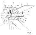
- Fig. 2 is a cutaway, schematic perspective representation of the apparatus according to Fig. 1; and
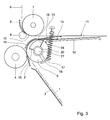
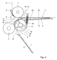
- Figs. 3 and 4 are similar views of the apparatus to Fig. 1, but in operative stages following the stage represented in Figs. 1 and 2.
- The apparatus according to the example represented in the drawing has a
document transport path 1 for transporting documents, of which in this example aspecimen 2 is represented in different stages of transport. Thedocument transport path 1 according to this example is determined by aguide 3, a pair ofopposite transport rollers guide 15. - For supplying envelopes there is provided an
envelope transport path 6. Theenvelope transport path 6 passes, according to this example, between on the one hand a set oftransport rollers 7 and on the other aguide 8 and a set of flap hold-open rollers 9. - Connected to the
envelope transport path 6 is aholder 10 for receiving and holding anenvelope 11 in a stuffing position aligned with theenvelope transport path 6. Theenvelope 11 is represented in the drawing in the stuffing position, and, for the purpose of illustration, cutaway on the viewing side. It is noted that within the framework of the present invention, it is also possible to provide that the envelope can reach the stuffing position exclusively or additionally by a route other than along apath 6 with the flap trailing, for instance in opposite direction, with the flap leading. The flap hold-open element 9 keeps theflap 12 of theenvelope 11 in the stuffing position open. - The
holder 10 also aligns with thedocument transport path 1 for receiving in anenvelope 11 in the stuffing position adocument 2 or documents coming from thedocument transport path 1. -
Guide strips document 2 coming from thedocument transport path 1 into theenvelope 11 in the stuffing position. - Adjacent the
guide 15,carriers 16 reach, via slots between thetransport rollers 5, into thedocument transport path 1 for engagement bydocuments 2 transported along thedocument transport path 1. Thecarriers 16 can be carried along bydocuments 2 transported along thedocument transport path 1, from a rest position (Figs. 1, 2, 4) to a carried position (Fig. 3). - The
guide strips carriers 16 for displacement from the retracted position to the projecting position in response to thecarriers 16 being carried along by adocument 2 engaging thecarriers 16. According to this example, this has been realized, as regards thecentral guide strips 14, in that thecarriers 16 also form carrier arms via which theguide strips 14 are suspended pivotably about the centerline of therollers 5. Further, thecarriers 16 are coupled with the outer guide strips via across bar 17, supportingarms shaft 21 of therollers 5. Thecarriers 16 are thus designed as rockers which are pivotable about theshaft 21 of thetransport roller 5 of thetransport path 1. - The
guide strips neckline 23 of the envelope away from theother wall 22 of theenvelope 11, and keeping it so, and for guidingdocuments 2, to prevent hooking, past theneckline 23 of theenvelope 11. - In the projecting position shown in Fig. 3, the (laterally) inner ones of the
guide strips 14 project further into the stuffing position than outer ones of theguide strips 13 and, in retracted position, seen in a view along a plane parallel to the envelope stuffing position, outer ones of theguide strips 13 project from a side of the inner ones of theguide strips 14 remote from the flap hold-open rollers 9 to the opposite side of the inner ones of theguide strips 14. Thus, in the projecting position, the inner ones of theguide strips 14 project deep into theenvelope 11 parallel or almost parallel to the envelope stuffing position, so that the envelope neckline is reliably opened to its deepest point, while the risk of damage to theenvelope 11 is small and the outer ones of theguide strips 13 open the envelope relative far closely along its edges, so that entering document are reliably prevented from clinging to the envelope neckline close to the outer edges of the envelope. - The
guide strips carrier 16 rotatable about an axis parallel to the envelope stuffing position, wherein the outer ones of theguide strips 13 extend from positions at thecarrier 16 that are located closer to the axis of rotation of thecarrier 16 than the positions from which the inner ones of theguide strips 14 project. In this manner the difference in angels at which the guide strips 13, 14 project into theenvelope 11, when in the projecting position is realized in a simple manner. - In operation, the
carriers 16 are carried along from the moment when adocument 2 advancing along thedocument transport path 1 reaches the position represented in Figs. 1 and 2. As the leading edge of thedocument 2 is held against or at least close to therollers 5 by theguide 15, thecarriers 16 are reliably pushed on by the advancing document. However, as soon as the leading edge of thedocument 2 reaches the downstream end of theguide 15, it gets an opportunity to leave the path of thecarriers 16, thereby coming off the carriers. The place where the advancement of thecarriers 16 by the leadingedge 2 of adocument 2 terminates is reliably determined by the place in the paths of travel of thecarriers 16 where the downstream end of the guide is situated. However, the termination of the carriers being carried along can also be determined in a different manner, for instance in that the carriers are so suspended that, upon being carried along, they leave the transport path at a particular point. - Owing to the
carriers 16 being carried along by adocument 2 engaging the carriers, the operation of the movement of theguide strips - Owing to the
carriers 16 reaching into thedocument transport path 1 for being carried along by adocument 2 following thedocument transport path 1, it can be realized in a simple manner that theguide strips document 2 reaches theenvelope 11, bring theenvelope 11 into the open position required for the insertion of thedocument 2. It is also possible, however, to arrange for the envelope to be timely held open in a different manner, for instance in that the carriers are carried along by the envelope, and the guide strips are coupled with the carriers via a transmission, so that they keep the envelope open as soon as it arrives in the stuffing position. - Owing to the
guide strips carriers 16 for displacement from the retracted position to the projecting position, driven by displacement of thecarriers 16, the transmission of the movement of thecarriers 16 to the movement of theguide strips - From the position represented in Fig. 4, the
envelope 11 can be discharged in a direction away from thetransport rollers envelope 11 between thetransport rollers transport roller 5 against the input sense, the supportingarms envelope 11. According to this example, the retraction of the strips to the retracted position is driven bysprings 24 engaging thecross bar 17.
Claims (7)
- An apparatus for inserting documents (2), comprising:a document transport path (1) for transporting documents (2);an envelope transport path (6) for transporting envelopes (11);a holder (10) aligned with the envelope transport path (6) for each time receiving and holding an envelope (11) in a stuffing position aligned with the envelope transport path (6); and aligned with the document transport path (1) for receiving in an envelope (11) in the stuffing position at least one document (2) coming from the document transport path (1);a flap hold-open element (9) for holding open a flap (12) of an envelope (11) in the stuffing position; anda plurality of guide strips (13, 14) reciprocable between a retracted position and a projecting position in which it reaches further into the stuffing position than in the retracted position, for guiding into an envelope (11) in the stuffing position at least one document (2) coming from the document transport path (1);wherein, in the projecting position, laterally inner ones of the guide strips (14) project further into the stuffing position than outer ones of the guide strips (13) and, in retracted position, seen in a view along a plane parallel to the envelope stuffing position, outer ones of the guide strips (13) project from a side of the inner ones of the guide strips (14) remote from the flap hold-open element (9) to the opposite side of the inner ones of the guide strips (14).
- An apparatus according to claim 1, wherein the guide strips (13, 14) are suspended from at least one carrier (16) rotatable about an axis parallel to the envelope stuffing position, wherein the outer ones of the guide strips (13) extend from positions at the at least one carrier (16) that are located closer to the axis of rotation of the carrier (16) than the positions from which the inner ones of the guide strips (14) project.
- An apparatus according to claim 2, wherein the at least one carrier (16) reaches into the document transport path (1) or the envelope transport path (6) for engagement by documents (2) or envelopes (11) transported along the document transport path (1) or the envelope transport path (6), which carrier (16) can be carried along by documents (2) or envelopes (11) transported along the document transport path (1) or the envelope transport path (6) from a rest position to a carried position;
wherein the guide strip (13, 14) is coupled with the at least one carrier (16) for displacement from the retracted position to the projecting position in response to the at least one carrier (16) being carried along by a document (2) engaging the at least one carrier (16) or an envelope (11) engaging the at least one carrier (16), and
wherein the inner ones of the guide strips extend from positions on the carrier that are rotatable along a trajectory of which at least a section is located more remote from the axis of rotation of the carrier than adjacent sections of the document transport path. - An apparatus according to claim 2 or 3, wherein the at least one carrier (16) reaches into the document transport path (1) for being carried along by a document (2) following the document transport path (1).
- An apparatus according to any one of the claims 2-4, further comprising a guide (15) which extends at least along a portion of the document or envelope transport path (1, 6) in which the at least one carrier (16) is movable.
- An apparatus according to claim 5, wherein the guide (15) has a downstream end adjacent a portion of the document or envelope transport path (1, 6) in which the at least one carrier (16) is movable.
- An apparatus according to any one of the claims 2-6, wherein the at least one carrier (16) is designed as a rocker which is pivotable about a shaft (21) of a transport roller (5) of the document or envelope transport path (1, 6).
Applications Claiming Priority (1)
| Application Number | Priority Date | Filing Date | Title |
|---|---|---|---|
| NL1027933A NL1027933C2 (en) | 2004-12-31 | 2004-12-31 | Device for embedding documents. |
Publications (3)
| Publication Number | Publication Date |
|---|---|
| EP1676718A2 true EP1676718A2 (en) | 2006-07-05 |
| EP1676718A3 EP1676718A3 (en) | 2010-01-27 |
| EP1676718B1 EP1676718B1 (en) | 2012-10-03 |
Family
ID=34974836
Family Applications (1)
| Application Number | Title | Priority Date | Filing Date |
|---|---|---|---|
| EP05078036A Ceased EP1676718B1 (en) | 2004-12-31 | 2005-12-29 | Retractable guide strips of an apparatus for inserting documents into envelopes |
Country Status (3)
| Country | Link |
|---|---|
| US (1) | US7401448B2 (en) |
| EP (1) | EP1676718B1 (en) |
| NL (1) | NL1027933C2 (en) |
Families Citing this family (5)
| Publication number | Priority date | Publication date | Assignee | Title |
|---|---|---|---|---|
| FR2876058B1 (en) * | 2004-10-01 | 2008-04-18 | Gianfranco Passoni | METHOD FOR AUTOMATICALLY LOADING LOW-DIMENSIONAL PIECES, ESPECIALLY DOCUMENTS, AND DEVICE FOR IMPLEMENTING SAID METHOD |
| EP2123474B1 (en) * | 2008-05-20 | 2011-08-24 | Neopost Technologies | Method and an apparatus for inserting a postal item into an envelope |
| US9150046B2 (en) * | 2009-10-29 | 2015-10-06 | Neopost Technologies | Envelope inserting apparatus |
| CN112938028A (en) * | 2021-02-19 | 2021-06-11 | 深圳市微露智能科技有限公司 | Document feeding mechanism and automatic document packaging equipment |
| US12129145B2 (en) * | 2021-05-27 | 2024-10-29 | Ricoh Company, Ltd. | Enclosing apparatus and image forming system |
Citations (1)
| Publication number | Priority date | Publication date | Assignee | Title |
|---|---|---|---|---|
| US4888938A (en) | 1988-12-30 | 1989-12-26 | Pitney Bowes Inc. | Envelope throat opening blade |
Family Cites Families (14)
| Publication number | Priority date | Publication date | Assignee | Title |
|---|---|---|---|---|
| GB1084262A (en) * | 1963-09-07 | 1900-01-01 | ||
| NL7708799A (en) * | 1977-08-10 | 1979-02-13 | Bell Telephone Mfg | ENVELOPE OPENING DEVICE AND ENVELOPE FILLING MACHINE USING THIS. |
| US4922689A (en) * | 1987-03-25 | 1990-05-08 | Bell & Howell Phillipsburg Company | Insertion machine |
| GB2218970B (en) * | 1988-04-08 | 1991-12-18 | Pitney Bowes Plc | Envelope transport means |
| FR2634692B1 (en) * | 1988-07-27 | 1990-09-14 | Alcatel Satmam | DEVICE FOR INSERTING PLEATS IN ENVELOPES |
| FR2634693B1 (en) * | 1988-07-27 | 1990-09-14 | Alcatel Satmam | INTEGRATED MAILING OFFICE ENVELOPE MACHINE |
| FR2634731B1 (en) * | 1988-07-27 | 1990-09-14 | Alcatel Satmam | DEVICE FOR OPENING BODIES OF ENVELOPES FOR LOADING THEM |
| US4852334A (en) * | 1988-09-12 | 1989-08-01 | Pitney Bowes Inc. | Envelope opening apparatus |
| US5125214A (en) * | 1989-04-14 | 1992-06-30 | Bell & Howell Company | Inserter station for envelope inserting |
| US5255498A (en) * | 1990-11-02 | 1993-10-26 | Pitney Bowes Inc. | Envelope stuffing apparatus |
| US5430990A (en) * | 1992-09-18 | 1995-07-11 | Long John A | Envelope stuffing apparatus |
| US5447015A (en) * | 1993-11-01 | 1995-09-05 | Pitney Bowes Inc. | High speed insertion device |
| US5675959A (en) * | 1996-01-18 | 1997-10-14 | Pitney Bowes Inc. | Opening fingers for envelope inserting apparatus |
| US7155878B2 (en) * | 2004-08-31 | 2007-01-02 | Pitney Bowes Inc. | Device for opening the throat of an envelope in an insertion station |
-
2004
- 2004-12-31 NL NL1027933A patent/NL1027933C2/en not_active IP Right Cessation
-
2005
- 2005-12-29 EP EP05078036A patent/EP1676718B1/en not_active Ceased
- 2005-12-29 US US11/322,147 patent/US7401448B2/en not_active Expired - Lifetime
Patent Citations (1)
| Publication number | Priority date | Publication date | Assignee | Title |
|---|---|---|---|---|
| US4888938A (en) | 1988-12-30 | 1989-12-26 | Pitney Bowes Inc. | Envelope throat opening blade |
Also Published As
| Publication number | Publication date |
|---|---|
| US7401448B2 (en) | 2008-07-22 |
| US20060144016A1 (en) | 2006-07-06 |
| EP1676718B1 (en) | 2012-10-03 |
| EP1676718A3 (en) | 2010-01-27 |
| NL1027933C2 (en) | 2006-07-03 |
Similar Documents
| Publication | Publication Date | Title |
|---|---|---|
| US3965644A (en) | Apparatus and method for mail preparation | |
| CA1300575C (en) | Envelope opening apparatus | |
| EP1676718B1 (en) | Retractable guide strips of an apparatus for inserting documents into envelopes | |
| CN102642645B (en) | Cover sleeving device of automatic tube packer | |
| EP1275523A2 (en) | Method and apparatus for inserting insert material into an envelope | |
| CA2091733C (en) | Envelope stuffing device | |
| US5737899A (en) | Insertion packet centering device | |
| JP6529792B2 (en) | Paper sheet pre-processing device | |
| US4649694A (en) | Envelope contents extraction system | |
| EP1770042A3 (en) | Apparatus for assembly of document sets into a single collated packet | |
| EP0330069A2 (en) | Device to frame photographic films | |
| US7172107B2 (en) | Envelope having improved overlap profile | |
| ES2367832T3 (en) | SYSTEM FOR DEPOSITING DOCUMENTS IN BOXES. | |
| EP0688682B1 (en) | Apparatus for unfolding documents | |
| CN105764705B (en) | For inserting files into equipment and correlation technique in envelope | |
| JPH05221197A (en) | Rotating and inserting device for documents and paper sheets | |
| EP1870252B1 (en) | Envelope flap closing system | |
| US7533510B2 (en) | Compact inserter | |
| EP1676719B1 (en) | Guide in a compact inserter | |
| EP1468840A3 (en) | Method and device for controlling envelope flap during insertion | |
| US20070084907A1 (en) | Envelope having improved overlap profile | |
| US7437862B2 (en) | Machine and method for inserting sheets into envelopes | |
| JP3196503U (en) | Conveying device for flat objects with the edge down, and mail sorter | |
| US7886797B2 (en) | Apparatus for automatically closing envelopes | |
| US20100229504A1 (en) | Inserting apparatus and method for inserting postal items into envelopes |
Legal Events
| Date | Code | Title | Description |
|---|---|---|---|
| PUAI | Public reference made under article 153(3) epc to a published international application that has entered the european phase |
Free format text: ORIGINAL CODE: 0009012 |
|
| AK | Designated contracting states |
Kind code of ref document: A2 Designated state(s): AT BE BG CH CY CZ DE DK EE ES FI FR GB GR HU IE IS IT LI LT LU LV MC NL PL PT RO SE SI SK TR |
|
| AX | Request for extension of the european patent |
Extension state: AL BA HR MK YU |
|
| PUAL | Search report despatched |
Free format text: ORIGINAL CODE: 0009013 |
|
| AK | Designated contracting states |
Kind code of ref document: A3 Designated state(s): AT BE BG CH CY CZ DE DK EE ES FI FR GB GR HU IE IS IT LI LT LU LV MC NL PL PT RO SE SI SK TR |
|
| AX | Request for extension of the european patent |
Extension state: AL BA HR MK YU |
|
| 17P | Request for examination filed |
Effective date: 20100727 |
|
| 17Q | First examination report despatched |
Effective date: 20100820 |
|
| AKX | Designation fees paid |
Designated state(s): DE FR GB |
|
| GRAP | Despatch of communication of intention to grant a patent |
Free format text: ORIGINAL CODE: EPIDOSNIGR1 |
|
| GRAS | Grant fee paid |
Free format text: ORIGINAL CODE: EPIDOSNIGR3 |
|
| GRAA | (expected) grant |
Free format text: ORIGINAL CODE: 0009210 |
|
| AK | Designated contracting states |
Kind code of ref document: B1 Designated state(s): DE FR GB |
|
| REG | Reference to a national code |
Ref country code: GB Ref legal event code: FG4D |
|
| REG | Reference to a national code |
Ref country code: DE Ref legal event code: R082 Ref document number: 602005036355 Country of ref document: DE Representative=s name: CBDL PATENTANWAELTE, DE |
|
| REG | Reference to a national code |
Ref country code: DE Ref legal event code: R096 Ref document number: 602005036355 Country of ref document: DE Effective date: 20121129 |
|
| PLBE | No opposition filed within time limit |
Free format text: ORIGINAL CODE: 0009261 |
|
| STAA | Information on the status of an ep patent application or granted ep patent |
Free format text: STATUS: NO OPPOSITION FILED WITHIN TIME LIMIT |
|
| 26N | No opposition filed |
Effective date: 20130704 |
|
| REG | Reference to a national code |
Ref country code: DE Ref legal event code: R097 Ref document number: 602005036355 Country of ref document: DE Effective date: 20130704 |
|
| REG | Reference to a national code |
Ref country code: FR Ref legal event code: PLFP Year of fee payment: 11 |
|
| REG | Reference to a national code |
Ref country code: FR Ref legal event code: PLFP Year of fee payment: 12 |
|
| REG | Reference to a national code |
Ref country code: FR Ref legal event code: PLFP Year of fee payment: 13 |
|
| PGFP | Annual fee paid to national office [announced via postgrant information from national office to epo] |
Ref country code: GB Payment date: 20211222 Year of fee payment: 17 Ref country code: FR Payment date: 20211224 Year of fee payment: 17 Ref country code: DE Payment date: 20211210 Year of fee payment: 17 |
|
| REG | Reference to a national code |
Ref country code: DE Ref legal event code: R082 Ref document number: 602005036355 Country of ref document: DE Representative=s name: CBDL PATENTANWAELTE GBR, DE |
|
| REG | Reference to a national code |
Ref country code: DE Ref legal event code: R119 Ref document number: 602005036355 Country of ref document: DE |
|
| GBPC | Gb: european patent ceased through non-payment of renewal fee |
Effective date: 20221229 |
|
| PG25 | Lapsed in a contracting state [announced via postgrant information from national office to epo] |
Ref country code: GB Free format text: LAPSE BECAUSE OF NON-PAYMENT OF DUE FEES Effective date: 20221229 Ref country code: DE Free format text: LAPSE BECAUSE OF NON-PAYMENT OF DUE FEES Effective date: 20230701 |
|
| PG25 | Lapsed in a contracting state [announced via postgrant information from national office to epo] |
Ref country code: FR Free format text: LAPSE BECAUSE OF NON-PAYMENT OF DUE FEES Effective date: 20221231 |