EP1676526A1 - Heart rate monitoring unit - Google Patents
Heart rate monitoring unit Download PDFInfo
- Publication number
- EP1676526A1 EP1676526A1 EP05028752A EP05028752A EP1676526A1 EP 1676526 A1 EP1676526 A1 EP 1676526A1 EP 05028752 A EP05028752 A EP 05028752A EP 05028752 A EP05028752 A EP 05028752A EP 1676526 A1 EP1676526 A1 EP 1676526A1
- Authority
- EP
- European Patent Office
- Prior art keywords
- belt
- heart rate
- electrode
- electronics unit
- base
- Prior art date
- Legal status (The legal status is an assumption and is not a legal conclusion. Google has not performed a legal analysis and makes no representation as to the accuracy of the status listed.)
- Granted
Links
- 238000012544 monitoring process Methods 0.000 title claims abstract description 23
- 238000004891 communication Methods 0.000 claims description 5
- 229920001971 elastomer Polymers 0.000 claims description 5
- 239000004576 sand Substances 0.000 claims 1
- 239000004033 plastic Substances 0.000 description 4
- 239000013536 elastomeric material Substances 0.000 description 2
- 239000000463 material Substances 0.000 description 2
- 239000000853 adhesive Substances 0.000 description 1
- 230000001070 adhesive effect Effects 0.000 description 1
- 230000003466 anti-cipated effect Effects 0.000 description 1
- 239000004020 conductor Substances 0.000 description 1
- 230000001351 cycling effect Effects 0.000 description 1
- 239000013013 elastic material Substances 0.000 description 1
- 239000000806 elastomer Substances 0.000 description 1
- 239000004744 fabric Substances 0.000 description 1
- 230000003993 interaction Effects 0.000 description 1
- 238000000034 method Methods 0.000 description 1
- 210000000707 wrist Anatomy 0.000 description 1
Images



Classifications
-
- A—HUMAN NECESSITIES
- A61—MEDICAL OR VETERINARY SCIENCE; HYGIENE
- A61B—DIAGNOSIS; SURGERY; IDENTIFICATION
- A61B5/00—Measuring for diagnostic purposes; Identification of persons
- A61B5/02—Detecting, measuring or recording for evaluating the cardiovascular system, e.g. pulse, heart rate, blood pressure or blood flow
- A61B5/024—Measuring pulse rate or heart rate
- A61B5/0245—Measuring pulse rate or heart rate by using sensing means generating electric signals, i.e. ECG signals
-
- A—HUMAN NECESSITIES
- A61—MEDICAL OR VETERINARY SCIENCE; HYGIENE
- A61B—DIAGNOSIS; SURGERY; IDENTIFICATION
- A61B5/00—Measuring for diagnostic purposes; Identification of persons
- A61B5/02—Detecting, measuring or recording for evaluating the cardiovascular system, e.g. pulse, heart rate, blood pressure or blood flow
- A61B5/024—Measuring pulse rate or heart rate
- A61B5/02438—Measuring pulse rate or heart rate with portable devices, e.g. worn by the patient
-
- A—HUMAN NECESSITIES
- A61—MEDICAL OR VETERINARY SCIENCE; HYGIENE
- A61B—DIAGNOSIS; SURGERY; IDENTIFICATION
- A61B5/00—Measuring for diagnostic purposes; Identification of persons
- A61B5/68—Arrangements of detecting, measuring or recording means, e.g. sensors, in relation to patient
- A61B5/6801—Arrangements of detecting, measuring or recording means, e.g. sensors, in relation to patient specially adapted to be attached to or worn on the body surface
- A61B5/683—Means for maintaining contact with the body
- A61B5/6831—Straps, bands or harnesses
-
- A—HUMAN NECESSITIES
- A61—MEDICAL OR VETERINARY SCIENCE; HYGIENE
- A61B—DIAGNOSIS; SURGERY; IDENTIFICATION
- A61B5/00—Measuring for diagnostic purposes; Identification of persons
- A61B5/68—Arrangements of detecting, measuring or recording means, e.g. sensors, in relation to patient
- A61B5/6801—Arrangements of detecting, measuring or recording means, e.g. sensors, in relation to patient specially adapted to be attached to or worn on the body surface
- A61B5/6843—Monitoring or controlling sensor contact pressure
Definitions
- the present invention relates generally to heart rate monitors, and more particularly, to heart rate monitors that include a circumferential belt for affixing the heart rate monitor to a user's chest.
- Heart rate monitors are worn on a person's chest and are held in place using a belt that is wrapped around the person's torso.
- the heart rate monitors typically include a pair of electrodes that must remain in contact with the user's skin in order to receive the heart rate signal.
- the heart rate monitor unit and electrodes are typically encased in a hard plastic cover. The plastic cover does not usually fit well against the user's chest. As a result, during rigorous exercise, such as running, cycling or jogging, the electrodes often lose contact with the user's skin.
- a heart rate monitor that comprises at least one electrode, an electronics unit in electrical communication with the at least one electrode, and a base.
- the electronics unit and the at least one electrode are supported by the base.
- the base includes a first bridging portion defined between the electronics unit and the at least one electrode.
- the first bridging portion includes at least one belt connection portion.
- the at least one electrode includes first and second electrodes
- the base has a length defining a longitudinal axis
- the electronics unit is disposed between the first and second electrodes along the longitudinal axis
- the first bridging portion is defined between the first electrode and electronics unit
- the base further includes a second bridging portion defined between the second electrode and the electronics unit.
- a heart rate monitor base that includes first and second electrode portions, an electronics unit portion disposed between the first and second electrode portions, and a first bridging portion defined between the first electrode portion and the electronics unit portion and a second bridging portion is defined between the second electrode portion and the electronics unit portion.
- the first bridging portion includes a first belt connection portion and the second bridging portion includes a second belt connection portion.
- a heart rate monitoring unit that includes a heart rate monitor and a belt.
- the heart rate monitor includes a base that is conformable to a user's chest and has a length defining a longitudinal axis, an electronics unit supported by the base, and first and second electrodes that are also supported by the base.
- the electronics unit is disposed between the first and second electrodes along the longitudinal axis, and the first and second electrodes are in electrical communication with the electronics unit.
- the base includes a first bridging portion defined between the electronics unit and the first electrode and a second bridging portion defined between the electronics unit and the second electrode.
- the first and second bridging portions have first and second openings defined therein, respectively, and the first and second openings each have a notch defined therein.
- the belt has first and second opposite ends that include first and second belt connectors, respectively.
- the first and second belt connectors each include a cylindrical portion having a flange extending therefrom. The cylindrical portion of the first belt connector is received by the first opening notch and the cylindrical portion of the second belt connector is received by the second opening notch.
- a heart rate monitor base having a length defining a longitudinal axis.
- the base includes an electronics unit portion, a first electrode portion, and a first belt connection portion.
- the electronics unit portion has a first end proximate the first electrode portion and a second end distal from the first electrode portion.
- the first electrode portion has a first end proximate the electronics unit portion and a second end distal from the electronics unit portion.
- the first belt connection portion is disposed between the second end of the electronics unit portion and the second end of first electrode portion.
- the heart rate monitor base further includes a second electrode portion having a first end proximate the second end of the electronics unit portion and a second end distal from the electronics unit portion, and a second belt connection portion disposed between the first end of the electronics unit portion and the second end of the second electrode portion.
- the second belt connection portion projects away from the electronics unit portion.
- the heart rate monitor base includes a first electrode secured to the first electrode portion, and an electronics unit secured to the electronics unit portion, thereby providing a heart rate monitor.
- the heart rate monitor described above includes a belt having first and second ends. The first end of the belt is connected to the first belt connection portion, thereby providing a heart rate monitoring unit.
- the second ends of the first and second electrode portions are each connected to the belt at a point between the first and second opposite ends of the belt
- the base is made of a flexible rubber
- at least a portion of the first belt connection portion overlaps with at least a portion of the first electrode portion along the longitudinal axis
- at least a portion of the second belt connection portion overlaps with at least a portion of the second electrode portion along the longitudinal axis
- the first and second electrode portions are pivotable with respect to the electronics unit portion and the first and second belt connection portions, respectively.
- the heart rate monitor 10 includes a base 14 that includes at least one and preferably two or more electrodes 16a and 16b and an electronics unit 18.
- the user's heart rate is measured by the electrodes 16a and 16b.
- a measurable potential difference is formed between the two electrodes 16a and 16b as the heart beats.
- the heart rate monitor 10 is fastened around the user's body by the belt 12, which is preferably made of an elastic material.
- the belt 12 can be made of a cloth, plastic or other elastomer, for example.
- the belt 12 can be any article for securing the base 14 to the user's body 100.
- the belt can be a strap, cord, rope, strip or the like.
- the heart rate monitor 10 can be adhered to the user's body 100 using a temporary adhesive. As shown in FIG. 1, the measured heart rate information is transmitted inductively, for instance, to a receiver 102 comprising means 104 for displaying the measured heart rate.
- the receiver 102 can be located on the user's wrist, on a bicycle the user is riding or in any other advantageous location for the user to read the measured heart rate.
- the heart rate monitor 10 can include means for storing, processing and displaying the pulse information, thereby making a separate receiver 102 unnecessary.
- the base 14 of the heart rate monitor 10 includes two electrodes 16a, 16b.
- the electrodes 16a and 16b are located on the underside 14a of the base 14. In this position, the electrodes 16a and 16b will contact the user's skin when the heart rate monitor 10 is fitted on the user.
- the electrodes 16a and 16b can be secured to the base 14 in a number of different ways. For example, the electrodes 16a and 16b can be adhered to the base 14 or disposed in an opening in the base 14 or can be press fit therein.
- the base 14 also includes an electronics unit 18 disposed between the two electrodes 16a, 16b.
- the electronics unit 18 is in electrical communication with the two electrodes 16, 16b via conductors 20.
- the electronics unit 18 processes the information obtained from the electrodes 16a, 16b.
- the electronics unit 18 includes, for example, means for receiving a signal from the electrodes 16a and 16b, means for detecting heart rate from the received signal, means for storing heart rate information and means for transmitting the heart rate information inductively to the receiver 102. It should be understood that the operation of the electronics unit 18 is only exemplary and those skilled in the art will readily understand the operation of the electronics unit 18 and its interaction with the accompanying electrodes 16a and 16b.
- the electronics unit 18 can be secured to the base 14 in a number of different ways.
- the electronics unit 18 can be adhered to the base 14 or in an opening in the base 14 or can be press fit therein.
- the base 14 is hollow and the electronics unit 18 is disposed therein.
- the base 14 is preferably made from an elastomeric material, such as a rubber, that is flexible and allows the base 14 to give and flex during use.
- the base 14 can also made of plastic or other material.
- the materials of which the different components of the invention are made is not a limitation on the present invention.
- the base 14 includes at least one and preferably two belt connection portions 22a and 22b and the belt 12 includes at least one and preferably two belt connectors 24a and 24b, respectively.
- a connection between the base 14 and the belt 12 can be implemented by any connection arrangement according to the invention, whereby the ends of the belt 12 and the base 14 are detachably connectable or they are fixedly connected together.
- the two belt connectors 24a and 24b on the opposite ends 12a and 12b of the belt 12 connect respectively to the belt connection portions 22a and 22b.
- the belt connection portions 22a and 22b are disposed on bridging portions 25a and 25b.
- Bridging portions 25a and 25b are the portion of base 14 defined between the electronics unit 18 and the electrodes 16a and 16b, respectively.
- belt connection portion 22a is included in bridging portion 25a between the electronics unit 18 and electrode 16a and belt connection portion 22b is disposed on bridging portion 25b between electronics unit 18 and electrode 16b.
- the belt connection portions are connection openings 22a and 22b that are defined in bridging portions 25a and 25b.
- each of the connection openings 22a and 22b include a notch 26.
- the belt connectors 24a and 24b include a cylindrical portion 28 having a disc-like portion or flange 30 extending therefrom.
- the flange 30 and cylindrical portion 28 of the belt connectors 24a and 24b are inserted into the connection openings 22a, 22b, respectively.
- the belt connectors 24a and 24b are moved into the notches 26 in a direction substantially parallel to the longitudinal axis L of the base 14, as shown in FIG. 2.
- the cylindrical portion 28 is then received by the notch 26.
- connection openings 22a and 22b have a diameter larger than the flanges 30 and the notches 26 have a diameter smaller than the flanges 30. This allows the belt connector 24 to be received in the connection opening 22 and then secured in the notch 26.
- the elasticity of the belt 12 helps the belt connectors 24a and 24b remain secure in the notches 26.
- the force directed from the body outwards, which causes the elastic belt 12 to stretch, benefits the connection by making the cylindrical portions 28 of the belt connectors 24a and 24b press against the surfaces defining the notches 26.
- connection openings 22a and 22b include a first notch 26a for receiving the cylindrical portion 28 and a second notch 26b for receiving the flange 30. This allows the flange 30 to be flush with the underside 14a of the base 14.
- connection openings 22a and 22b and cylindrical portion 28 and flanges 30 can be reversed.
- the connection openings can be defined in the belt 12 and the cylindrical portions 28 and flanges 30 can be disposed on the bridging portions 25a and 25b.
- the belt connection portions 22a and 22b and the belt connectors 24a and 24b can comprise any known connection solution.
- the belt connection portions 22a and 22b and the belt connectors 24a and 24b may comprise buttons, snaps, buckles or the like.
- the belt connection portions 22a and 22b inboard of the electrodes 16a and 16b, when the belt 12 is connected to the heart rate monitor 10 and the entire heart rate monitoring unit 32 (the belt 12 plus the heart rate monitor 10) is fitted around a user's body, a portion of the belt 12 presses against the top surface 14b of the base 14.
- This arrangement helps secure the electrodes 16a and 16b against the user's body. This can be advantageous during rigorous exercise where the prior art heart rate monitors may have a tendency to lose contact between the electrodes and the user's body.
- the base 14 has an arcuate shape. This also helps keep the electrodes 16a and 16b remain in contact with the user's body.
- FIGS. 6 and 7 A second preferred embodiment of a heart rate monitor 60 of the present invention is shown in FIGS. 6 and 7.
- the base 14 includes constricted portions 62a and 62b disposed between the electrodes 16a and 16b and the electronics unit 18.
- the constricted portions 62a and 62b are defined in the bridging portions 25a and 25b.
- the electrodes 16a and 16b define a first width
- the constricted portions 62a and 62b define a second width
- the first width is greater than the second width.
- the base 14 is preferably made from an elastomeric material, such as a rubber, that is flexible and allows the base 14 to give and flex during use.
- the constricted portions 62a and 62b provide for even more flexibility. As will be appreciated by those skilled in the art, the constricted portions 62a and 62b allow the electrodes 16a and 16b to move in an up and down direction (see the arrows in FIG. 6) while a user is exercising. This feature allows the electrodes 16a and 16b to remain in contact with the user's body during rigorous exercise.
- FIGS. 8-12 A third preferred embodiment of a heart rate monitor 70 of the present invention is shown in FIGS. 8-12.
- the monitor 70 includes a base 72 having an electronics unit portion 74, belt connection portions 76a and 76b and electrode portions 78a and 78b.
- the electronics unit portion 74 has opposite ends 74a and 74b
- electrode portion 78a has opposite ends 78c and 78d
- electrode portion 78b has opposite ends 78e and 78f.
- belt connection portion 76a has opposite ends 76c and 76d
- belt connection portion 76d has opposite ends 76e and 76f.
- the electronics unit portion 74 includes an electronics unit 18 secured thereto.
- the electronics unit 18 is disposed inside the electronics unit portion 74.
- the electronics unit 18 can be secured to the outside of the electronics unit portion 74.
- the electrode portions 78a and 78b include electrodes 16a and 16b secured thereto.
- the distal ends 76c and 76f of the belt connection portions 76a and 76b extend away from the ends 74a and 74b of the electronics unit portion 74, as do the distal ends 78c and 78f of the electrode portions 78a and 78b.
- the belt connection portions 76a and 76b overlap the electrode portions 78a and 78b along the longitudinal axis L.
- the electrode portions 78a and 78b are pivotable with respect to the electronics unit portion 74 and the first and second belt connection portions 76a and 76b, respectively.
- the presently described embodiment of the present invention anticipates belt connection portion 76a being disposed anywhere between end 74b of the electronics unit portion 74 and end 78c of electrode portion 76a. And, the present invention anticipates belt connection portion 76b being disposed anywhere between end 74a of the electronics unit portion 74 and end 78f of electrode portion 76b. In other words, the ends 76c and 76f of the belt connection portions 76a and 76b are positioned inboard of the ends 78c and 78f of the electrode portions 78a and 78b.
- the belt connectors 24a and 24b of the belt 12 comprise slot-disc portions 80 (having an extension 80a and disc 80b) and the belt connection portions include corresponding casing slots 82 and openings 84.
- the slot-disc portions 80 are inserted into the casing slots 82, and the disc 84 is biased into the opening. This secures the belt 12 to the base 72.
- This arrangement is not a limitation on the present invention. It will be understood that any known connection or fastening solution is anticipated.
- the belt connection portions 76a and 76b and the belt connectors 24a and 24b may comprise buttons, snaps, buckles or the like.
- the belt 12 may be adjustable.
- the electrode portions 78a and 78b include an adjustable engagement member 86 on the ends 78c and 78f thereof.
- the adjustable engagement members 86 each define a space 88 through which the belt 12 passes when the heart rate monitoring unit is secured to a user's body. The belt 12 can move within the space 88 during exercise. This arrangement helps hold the electrode portions 78a and 78b, and, therefore, the electrodes 16a and 16b against the user's body.
- Other connection solutions can also be included at the ends 78c and 78f of the electrode portions 78a and 78b.
- Other adjustable arrangements can be used, for example, the adjustable engagement member may define an enclosed space.
- non adjustable arrangements, such as buttons, snaps, stitching or buckles can be used.
- the adjustable engagement members 86 can be omitted. As is shown in FIG. 11, this embodiment can also include constriction portions 62a and 62b.
Landscapes
- Health & Medical Sciences (AREA)
- Life Sciences & Earth Sciences (AREA)
- Engineering & Computer Science (AREA)
- Heart & Thoracic Surgery (AREA)
- Molecular Biology (AREA)
- Physics & Mathematics (AREA)
- Cardiology (AREA)
- Biophysics (AREA)
- Pathology (AREA)
- Biomedical Technology (AREA)
- Veterinary Medicine (AREA)
- Medical Informatics (AREA)
- Public Health (AREA)
- Surgery (AREA)
- Animal Behavior & Ethology (AREA)
- General Health & Medical Sciences (AREA)
- Physiology (AREA)
- Signal Processing (AREA)
- Measuring Pulse, Heart Rate, Blood Pressure Or Blood Flow (AREA)
- Measurement And Recording Of Electrical Phenomena And Electrical Characteristics Of The Living Body (AREA)
Abstract
Description
- The present invention relates generally to heart rate monitors, and more particularly, to heart rate monitors that include a circumferential belt for affixing the heart rate monitor to a user's chest.
- It is common to monitor a person's heart rate both for exercise or for other medical reasons. Many heart rate monitors are worn on a person's chest and are held in place using a belt that is wrapped around the person's torso. The heart rate monitors typically include a pair of electrodes that must remain in contact with the user's skin in order to receive the heart rate signal. However, the heart rate monitor unit and electrodes are typically encased in a hard plastic cover. The plastic cover does not usually fit well against the user's chest. As a result, during rigorous exercise, such as running, cycling or jogging, the electrodes often lose contact with the user's skin.
- Thus, a need has arisen for a heart rate monitor that allows the electrodes to remain in contact with the user's skin even during rigorous exercise.
- In accordance with a first aspect of the present invention, there is provided a heart rate monitor that comprises at least one electrode, an electronics unit in electrical communication with the at least one electrode, and a base. The electronics unit and the at least one electrode are supported by the base. The base includes a first bridging portion defined between the electronics unit and the at least one electrode. The first bridging portion includes at least one belt connection portion. In a preferred embodiment, the at least one electrode includes first and second electrodes, the base has a length defining a longitudinal axis, the electronics unit is disposed between the first and second electrodes along the longitudinal axis, the first bridging portion is defined between the first electrode and electronics unit, and the base further includes a second bridging portion defined between the second electrode and the electronics unit.
- In accordance with another aspect of the present invention there is provided a heart rate monitor base that includes first and second electrode portions, an electronics unit portion disposed between the first and second electrode portions, and a first bridging portion defined between the first electrode portion and the electronics unit portion and a second bridging portion is defined between the second electrode portion and the electronics unit portion. The first bridging portion includes a first belt connection portion and the second bridging portion includes a second belt connection portion.
- In accordance with another aspect of the present invention, there is provided a heart rate monitoring unit that includes a heart rate monitor and a belt. The heart rate monitor includes a base that is conformable to a user's chest and has a length defining a longitudinal axis, an electronics unit supported by the base, and first and second electrodes that are also supported by the base. The electronics unit is disposed between the first and second electrodes along the longitudinal axis, and the first and second electrodes are in electrical communication with the electronics unit. The base includes a first bridging portion defined between the electronics unit and the first electrode and a second bridging portion defined between the electronics unit and the second electrode. The first and second bridging portions have first and second openings defined therein, respectively, and the first and second openings each have a notch defined therein. The belt has first and second opposite ends that include first and second belt connectors, respectively. The first and second belt connectors each include a cylindrical portion having a flange extending therefrom. The cylindrical portion of the first belt connector is received by the first opening notch and the cylindrical portion of the second belt connector is received by the second opening notch.
- In accordance with yet another aspect of the present invention, there is provided a heart rate monitor base having a length defining a longitudinal axis. The base includes an electronics unit portion, a first electrode portion, and a first belt connection portion. The electronics unit portion has a first end proximate the first electrode portion and a second end distal from the first electrode portion. The first electrode portion has a first end proximate the electronics unit portion and a second end distal from the electronics unit portion. The first belt connection portion is disposed between the second end of the electronics unit portion and the second end of first electrode portion. In a preferred embodiment, the heart rate monitor base further includes a second electrode portion having a first end proximate the second end of the electronics unit portion and a second end distal from the electronics unit portion, and a second belt connection portion disposed between the first end of the electronics unit portion and the second end of the second electrode portion. In this embodiment, the second belt connection portion projects away from the electronics unit portion.
- In another preferred embodiment, the heart rate monitor base includes a first electrode secured to the first electrode portion, and an electronics unit secured to the electronics unit portion, thereby providing a heart rate monitor.
- In another preferred embodiment, the heart rate monitor described above includes a belt having first and second ends. The first end of the belt is connected to the first belt connection portion, thereby providing a heart rate monitoring unit.
- In other preferred embodiments of the heart rate monitoring unit, the second ends of the first and second electrode portions are each connected to the belt at a point between the first and second opposite ends of the belt, the base is made of a flexible rubber, at least a portion of the first belt connection portion overlaps with at least a portion of the first electrode portion along the longitudinal axis, at least a portion of the second belt connection portion overlaps with at least a portion of the second electrode portion along the longitudinal axis, and the first and second electrode portions are pivotable with respect to the electronics unit portion and the first and second belt connection portions, respectively.
- The invention may be more readily understood by referring to the accompanying drawings in which:
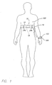
- FIG. 1 is a an elevational view showing a heart rate monitoring unit including a heart rate monitor and belt secured on a person's chest in accordance with a first preferred embodiment of the present invention;
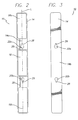
- FIG. 2 is a bottom elevational view of the heart rate monitor of FIG. 1 showing the underside of the base and its components;
- FIG. 3 is a top elevational view of the heart rate monitor of FIG. 1 showing the top surface of the base;
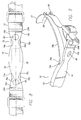
- FIG. 4 is an exploded view of the heart rate monitor of FIG. 1 and the belt;
- FIG. 5 is a side elevational view of the heart rate monitoring unit of FIG. 1, showing the base in cross-section;
- FIG. 6 is a bottom elevational view of a heart rate monitor having constricted portions in accordance with a second preferred embodiment of the present invention;
- FIG. 7 is a side elevational view of the heart rate monitor of FIG. 6;
- FIG. 8 is a top elevational view of a heart rate monitoring unit in accordance with a fifth preferred embodiment of the present invention;
- FIG. 9 is a perspective view of a portion of the heart rate monitoring unit of FIG. 8 showing the electrode portion pivoting away from the electronics unit portion and belt connection portion;
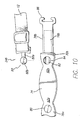
- FIG. 10 is an exploded view of a portion of the heart rate monitoring unit of FIG. 8 showing how the belt connectors connect to the belt connection portion;
- FIG. 11 is a side elevation view of the heart rate monitor base of FIG. 8 showing the electrode portions, belt connection portions, electronics unit portion, and their respective ends;
- FIG. 12 is a bottom elevational view of the heart rate monitoring unit of FIG. 8.
- Like numerals refer to like parts throughout the several views of the drawings.
- Referring to FIG. 1, a person (also referred to as a user) 100 wearing a
heart rate monitor 10 is shown. Theheart rate monitor 10 is held in place by abelt 12. With reference to FIG. 2, theheart rate monitor 10 includes abase 14 that includes at least one and preferably two ormore electrodes electronics unit 18. The user's heart rate is measured by theelectrodes electrodes - The
heart rate monitor 10 is fastened around the user's body by thebelt 12, which is preferably made of an elastic material. Thebelt 12 can be made of a cloth, plastic or other elastomer, for example. Thebelt 12 can be any article for securing thebase 14 to the user'sbody 100. For example, the belt can be a strap, cord, rope, strip or the like. In an alternative embodiment, theheart rate monitor 10 can be adhered to the user'sbody 100 using a temporary adhesive. As shown in FIG. 1, the measured heart rate information is transmitted inductively, for instance, to areceiver 102 comprising means 104 for displaying the measured heart rate. Thereceiver 102 can be located on the user's wrist, on a bicycle the user is riding or in any other advantageous location for the user to read the measured heart rate. Alternatively, theheart rate monitor 10 can include means for storing, processing and displaying the pulse information, thereby making aseparate receiver 102 unnecessary. - With reference to FIGS. 2 and 3, the
base 14 of theheart rate monitor 10 includes twoelectrodes electrodes base 14. In this position, theelectrodes heart rate monitor 10 is fitted on the user. It will be understood that theelectrodes electrodes - As shown in FIG. 2, the
base 14 also includes anelectronics unit 18 disposed between the twoelectrodes electronics unit 18 is in electrical communication with the twoelectrodes 16, 16b viaconductors 20. Theelectronics unit 18 processes the information obtained from theelectrodes electronics unit 18 includes, for example, means for receiving a signal from theelectrodes receiver 102. It should be understood that the operation of theelectronics unit 18 is only exemplary and those skilled in the art will readily understand the operation of theelectronics unit 18 and its interaction with the accompanyingelectrodes electronics unit 18 can be secured to the base 14 in a number of different ways. For example, theelectronics unit 18 can be adhered to the base 14 or in an opening in the base 14 or can be press fit therein. Furthermore, in a preferred embodiment, thebase 14 is hollow and theelectronics unit 18 is disposed therein. - The
base 14 is preferably made from an elastomeric material, such as a rubber, that is flexible and allows the base 14 to give and flex during use. The base 14 can also made of plastic or other material. However, the materials of which the different components of the invention are made is not a limitation on the present invention. - As shown in FIGS. 4 and 5, the
base 14 includes at least one and preferably twobelt connection portions belt 12 includes at least one and preferably twobelt connectors belt 12 can be implemented by any connection arrangement according to the invention, whereby the ends of thebelt 12 and the base 14 are detachably connectable or they are fixedly connected together. However, as shown in the figures, in a preferred embodiment, the twobelt connectors belt 12 connect respectively to thebelt connection portions - In a preferred embodiment, the
belt connection portions portions 25a and 25b. Bridgingportions 25a and 25b are the portion ofbase 14 defined between theelectronics unit 18 and theelectrodes belt connection portion 22a is included in bridging portion 25a between theelectronics unit 18 andelectrode 16a andbelt connection portion 22b is disposed on bridgingportion 25b betweenelectronics unit 18 andelectrode 16b. - In a preferred embodiment, the belt connection portions are
connection openings portions 25a and 25b. Preferably, each of theconnection openings notch 26. Thebelt connectors cylindrical portion 28 having a disc-like portion orflange 30 extending therefrom. To connect theheart rate monitor 10 to thebelt 12, theflange 30 andcylindrical portion 28 of thebelt connectors connection openings belt connectors notches 26 in a direction substantially parallel to the longitudinal axis L of thebase 14, as shown in FIG. 2. Thecylindrical portion 28 is then received by thenotch 26. It will be understood that theconnection openings flanges 30 and thenotches 26 have a diameter smaller than theflanges 30. This allows the belt connector 24 to be received in the connection opening 22 and then secured in thenotch 26. - When fitted around a user's body, the elasticity of the
belt 12 helps thebelt connectors notches 26. The force directed from the body outwards, which causes theelastic belt 12 to stretch, benefits the connection by making thecylindrical portions 28 of thebelt connectors notches 26. - In a preferred embodiment, as shown in FIG. 5, the
connection openings cylindrical portion 28 and asecond notch 26b for receiving theflange 30. This allows theflange 30 to be flush with the underside 14a of thebase 14. - In another embodiment, the arrangement of the
connection openings cylindrical portion 28 andflanges 30 can be reversed. The connection openings can be defined in thebelt 12 and thecylindrical portions 28 andflanges 30 can be disposed on thebridging portions 25a and 25b. It will be understood that thebelt connection portions belt connectors belt connection portions belt connectors - Due to the placement of the
belt connection portions electrodes belt 12 is connected to theheart rate monitor 10 and the entire heart rate monitoring unit 32 (thebelt 12 plus the heart rate monitor 10) is fitted around a user's body, a portion of thebelt 12 presses against thetop surface 14b of thebase 14. This arrangement helps secure theelectrodes base 14 has an arcuate shape. This also helps keep theelectrodes - A second preferred embodiment of a
heart rate monitor 60 of the present invention is shown in FIGS. 6 and 7. In accordance with this embodiment, thebase 14 includesconstricted portions electrodes electronics unit 18. Theconstricted portions bridging portions 25a and 25b. As shown in FIG. 5, theelectrodes constricted portions - As described above, the
base 14 is preferably made from an elastomeric material, such as a rubber, that is flexible and allows the base 14 to give and flex during use. Theconstricted portions constricted portions electrodes electrodes - A third preferred embodiment of a
heart rate monitor 70 of the present invention is shown in FIGS. 8-12. In this embodiment, themonitor 70 includes a base 72 having anelectronics unit portion 74,belt connection portions electrode portions electronics unit portion 74 has opposite ends 74a and 74b,electrode portion 78a has opposite ends 78c and 78d, andelectrode portion 78b has opposite ends 78e and 78f. Furthermore,belt connection portion 76a has opposite ends 76c and 76d, andbelt connection portion 76d has opposite ends 76e and 76f. - As shown in FIG. 8, the
electronics unit portion 74 includes anelectronics unit 18 secured thereto. In a preferred embodiment, theelectronics unit 18 is disposed inside theelectronics unit portion 74. However, in other embodiments, theelectronics unit 18 can be secured to the outside of theelectronics unit portion 74. Theelectrode portions electrodes - As is shown in FIG. 11, the distal ends 76c and 76f of the
belt connection portions ends 74a and 74b of theelectronics unit portion 74, as do the distal ends 78c and 78f of theelectrode portions belt connection portions electrode portions belt 12 is connected to theheart rate monitor 70, thebelt 12 holds theelectrode portions electrodes electrode portions electrode portions electrode portion 78b is shown) are pivotable with respect to theelectronics unit portion 74 and the first and secondbelt connection portions - It will be understood that the presently described embodiment of the present invention anticipates
belt connection portion 76a being disposed anywhere betweenend 74b of theelectronics unit portion 74 andend 78c ofelectrode portion 76a. And, the present invention anticipatesbelt connection portion 76b being disposed anywhere between end 74a of theelectronics unit portion 74 andend 78f ofelectrode portion 76b. In other words, theends belt connection portions ends electrode portions - In a preferred embodiment, the
belt connectors belt 12 comprise slot-disc portions 80 (having an extension 80a and disc 80b) and the belt connection portions include correspondingcasing slots 82 andopenings 84. As will be understood by those skilled in the art, the slot-disc portions 80 are inserted into thecasing slots 82, and thedisc 84 is biased into the opening. This secures thebelt 12 to thebase 72. This arrangement is not a limitation on the present invention. It will be understood that any known connection or fastening solution is anticipated. For example, thebelt connection portions belt connectors belt 12 may be adjustable. - As is shown in FIGS. 9 and 12, in a preferred embodiment, the
electrode portions adjustable engagement member 86 on theends adjustable engagement members 86 each define a space 88 through which thebelt 12 passes when the heart rate monitoring unit is secured to a user's body. Thebelt 12 can move within the space 88 during exercise. This arrangement helps hold theelectrode portions electrodes ends electrode portions adjustable engagement members 86 can be omitted. As is shown in FIG. 11, this embodiment can also includeconstriction portions - The embodiments described above are exemplary embodiments of a the present invention. Those skilled in the art may now make numerous uses of, and departures from, the above-described embodiments without departing from the inventive concepts disclosed herein. Accordingly, the present invention is to be defined solely by the scope of the following claims.
Claims (31)
- A heart rate monitor (10) comprising,
at least one electrode (16),
an electronics unit (18), wherein the electronics unit (18) is in electrical communication with the at least one electrode (16), and
a base (14), wherein the electronics unit (18) and the at least one electrode (16) are supported by the base (14), the base (14) includes a first bridging portion (25a) defined between the electronics unit (18) and the at least one electrode (16), and the first bridging portion (25a) includes at least one belt connection portion (22a, 22b). - The heart rate monitor (10) of claim 1 wherein the at least one electrode (16) comprises first and second electrodes (16a, 16b), the base (14) has a length defining a longitudinal axis (L), the electronics unit (18) is disposed between the first and second electrodes (16a, 16b) along the longitudinal axis (L), the first bridging portion (25a) is defined between the first electrode (16a) and electronics unit (18), and the base (14) further comprises a second bridging portion (25b) defined between a sand the electronics unit (18).
- The heart rate monitor (10) of claim 2 wherein the at least one belt connection portion (22a, 22b) comprises first and second belt connection portion (22a, 22b), and the first belt connection portion (22a) is disposed on the first bridging portion (25a) and the second belt connection portion (22b) is disposed on the second bridging portion (25b).
- The heart rate monitor (10) of claim 1 wherein the at least one belt connection portion (22a, 22b) comprises an opening (22) defined in the first bridging portion (25a) and the opening includes a notch (26) defined therein.
- The heart rate monitor (10) of claim 3 wherein the first and second belt connection portions (22a, 22b) comprise first and second openings (22a, 22b) defined in the first and second bridging portions (25a, 25b), and wherein the first and second openings (22a, 22b) each include a notch (26) defined therein.
- The heart rate monitor (10) of claim 1 wherein the base (14) is conformable to a user's body part.
- The heart rate monitor (10) of claim 1 wherein the base (14) has an arcuate shape.
- The heart rate monitor (10) of claim 1 wherein the first bridging portion (25a) includes a constricted portion (62).
- The heart rate monitor (10) of claim 3 wherein the first and second bridging portions (25a, 25b) each include a constricted portion (62a, 62b).
- The heart rate monitor (10) of claim 8 wherein the at least one electrode (16) defines a first width, the constricted portion (62) defines a second width, and the first width is greater than the second width.
- The heart rate monitor (10) of claim 3 further comprising a belt (12) having first and second opposite ends(12a, 12b), wherein the first end (12a) includes a first belt connector (24a) and the second end (12b) includes a second belt connector (24b), and the first and second belt connectors (24a, 24b) are coupled with the first and second belt connection portions (22a, 22b), respectively.
- The heart rate monitor (10) of claim 11 wherein the first and second belt connection portions (22a, 22b) comprise first and second openings that each have a notch (26) defined therein, and the first and second belt connectors (24a, 24b) each comprise a cylindrical portion (28) having a flange (30) extending therefrom, and
wherein the cylindrical portion (28) of the first belt connector (24a) is received by the first opening notch (26) and the cylindrical portion (28) of the second belt connector (24b) is received by the second opening notch (26). - The heart rate monitor (10) of claim 11 wherein the first and second belt connection portions (22a, 22b) each comprise a cylindrical portion (28) having a flange (30) extending therefrom, and the first and second belt connectors (24a, 24b) comprise first and second openings that each have a notch (26) defined therein, and
wherein the cylindrical portion (28) of the first belt connection portion (22a) is received by the first opening notch (26) and the cylindrical portion (28) of the second belt connection portion (22b) is received by the second opening notch (26). - The heart rate monitor (10) of claim 1 wherein the heart rate monitor (10) is secured to a user's body by a belt (12), the belt (12) includes at least one belt connector (24a, 24b) that is coupled to the at least one belt connection portion (22a, 22b) of the base (14), and the at least one electrode (16) is positioned between the belt (12) and the user's body.
- A heart rate monitor (10) base (14) comprising,
first and second electrode portions (78a, 78b),
an electronics unit portion (74) disposed between the first and second electrode portions (78a, 78b), wherein a first bridging portion (25a) is defined between the first electrode portion (78a) and the electronics unit portion (74) and a second bridging portion (25b) is defined between the second electrode portion (78b) and the electronics unit portion (74), and
wherein the first bridging portion (25a) includes a first belt connection portion (22a) and the second bridging portion (25b) includes a second belt connection portion (22b). - A heart rate monitoring unit (32) comprising,a. a heart rate monitor (10), the heart rate monitor (10) includingi. a base (14), wherein the base (14) has a length defining a longitudinal axis (L), and is conformable to a user's chest,ii. an electronics unit (18), wherein the electronics unit (18) is supported by the base (14),iii. first and second electrodes (16a, 16b), wherein the first and second electrodes (16a, 16b) are supported by the base (14), the electronics unit (18) is disposed between the first and second electrodes (16a, 16b) along the longitudinal axis (L), and the first and second electrodes (16a, 16b) are in electrical communication with the electronics unit (18), andiv. wherein base (14) includes a first bridging portion (25a) defined between the electronics unit (18) and the first electrode (16a) and a second bridging portion (25b) defined between the electronics unit (18) and the second electrode (16b), the first and second bridging portions (25a, 25b) have first and second openings defined therein, respectively, and the first and second openings each have a notch (26) defined therein, andb. a belt (12) having first and second opposite ends (12a, 12b), wherein the first end (12a) includes a first belt connector (24a) and the second end (12b) includes a second belt connector (24b),i. wherein the first and second belt connectors (24a, 24b) each include a cylindrical portion (28) having a flange (30) extending therefrom, andii. wherein the cylindrical portion (28) of the first belt connector (24a) is received by the first opening notch (26a) and the cylindrical portion (28) of the second belt connector (24b) is received by the second opening notch (26b).
- A heart rate monitor base (14) having a length defining a longitudinal axis (L), the base (14) comprising:a. an electronics unit portion (74),b. a first electrode portion (78a), andc. a first belt connection portion (22a), wherein the electronics unit portion (74) has a first end (74a) proximate the first electrode portion (78a) and a second end (74b) distal from the first electrode portion (78a), the first electrode portion (78a) has a first end (78c) proximate the electronics unit portion (74) and a second end (78d) distal from the electronics unit portion (74), the first belt connection portion (22a) is disposed between the second end (74b) of the electronics unit portion (74) and the second end (78d) of first electrode portion (78a).
- The heart rate monitor base (14) of claim 17 further comprising:a. a second electrode portion (78b) having a first end (78e) proximate the second end (74b) of the electronics unit portion (74) and a second end (78f) distal from the electronics unit portion (74), andb. a second belt connection portion (22b) disposed between the first end (74a) of the electronics unit portion (74) and the second end (78f) of the second electrode portion (78b), wherein the second belt connection portion (22b) projects away from the electronics unit portion (74).
- A heart rate monitor (10) comprising:the heart rate monitor base (14) of claim 17,a first electrode (16a) secured to the first electrode portion (78a), andan electronics unit (18) secured to the electronics unit portion (74).
- A heart rate monitor (10) comprising:the heart rate monitor base (14) of claim 18,a first electrode (16a) secured to the first electrode portion (78a),a second electrode (16b) secured to the second electrode portion (78b), andan electronics unit (18) secured to the electronics unit portion (74).
- A heart rate monitoring unit (32), comprising:a. the heart rate monitor (10) of claim 19, andb. a belt (12) having first and second ends (12a, 12b), wherein the first end (12a) of the belt (12) is connected to the first belt connection portion (22a).
- A heart rate monitoring unit (32), comprising:the heart rate monitor base (14) of claim 20; anda belt (12) having first and second ends (12a, 12b), wherein the first end (12a) of the belt (12) is connected to the first belt connection portion (22a), and the second end (12b) of the belt (12) is connected to the second belt connection portion (22b).
- The heart rate monitoring unit (32) of claim 22
wherein at least a portion of the first belt connection portion (22a) overlaps with at least a portion of the first electrode portion (78a) along the longitudinal axis (L), and at least a portion of the second belt connection portion (22b) overlaps with at least a portion of the second electrode portion (78b) along the longitudinal axis (L), and
wherein the second ends (78d, 78f) of the first and second electrode portions (78a, 78b) are each connected to the belt (12) at a point between the first and second opposite ends (12a, 12b) of the belt (12). - The heart rate monitoring unit (32) of claim 22 wherein the first and second ends (12a, 12b) of the belt (12) include first and second belt connectors (24a, 24b), respectively, and the first and second belt connectors (24a, 24b) are connected to the first and second belt connection portions (22a, 22b) of the base (14), respectively.
- The heart rate monitoring unit (32) of claim 24 wherein the first and second belt connectors (24a, 24b) each comprise a disc (80b), and the first and second belt connection portions (22a, 22b) each comprise an opening (84) defined therein for receiving the discs (80b) of the first and second belt connectors (24a, 24b).
- The heart rate monitoring unit (32) of claim 23 wherein the second ends (78d, 78f) of the first and second electrode portions (78a, 78b) are adjustably connected to the belt (12).
- The heart rate monitoring unit (32) of claim 22 wherein the first and second electrode portions (78a, 78b) are pivotable with respect to the electronics unit portion (74) and the first and second belt connection portions (22a, 22b), respectively.
- The heart rate monitor base (14) of claim 17 wherein the base (14) is comprised of a flexible rubber.
- The heart rate monitor base (14) of claim 17 wherein the first belt connection portion (22a) is secured to the electronics unit portion (74).
- The heart rate monitoring base (14) of claim 17 wherein the first belt connection portion (22a) overlaps the first electrode portion (78a) along the longitudinal axis (L).
- The heart rate monitoring unit (32) of claim 21 wherein the belt (12) overlaps the first electrode portion (78a).
Applications Claiming Priority (1)
| Application Number | Priority Date | Filing Date | Title |
|---|---|---|---|
| US11/028,876 US7167737B2 (en) | 2005-01-03 | 2005-01-03 | Heart rate monitoring unit |
Publications (2)
| Publication Number | Publication Date |
|---|---|
| EP1676526A1 true EP1676526A1 (en) | 2006-07-05 |
| EP1676526B1 EP1676526B1 (en) | 2009-09-23 |
Family
ID=36054428
Family Applications (1)
| Application Number | Title | Priority Date | Filing Date |
|---|---|---|---|
| EP05028752A Expired - Lifetime EP1676526B1 (en) | 2005-01-03 | 2005-12-30 | Heart rate monitoring unit |
Country Status (7)
| Country | Link |
|---|---|
| US (1) | US7167737B2 (en) |
| EP (1) | EP1676526B1 (en) |
| JP (1) | JP2006187615A (en) |
| CN (1) | CN100536763C (en) |
| BR (1) | BRPI0505799A (en) |
| DE (1) | DE602005016770D1 (en) |
| TW (1) | TWI286071B (en) |
Cited By (5)
| Publication number | Priority date | Publication date | Assignee | Title |
|---|---|---|---|---|
| JP2006187615A (en) * | 2005-01-03 | 2006-07-20 | Shimano Inc | Heart rate monitor |
| EP2737846A1 (en) * | 2012-11-28 | 2014-06-04 | Seiko Instruments Inc. | Biological information detecting device |
| WO2017051087A1 (en) * | 2015-09-24 | 2017-03-30 | Billard Jean-Christophe | Device for acquiring electrical signals generated by the body |
| US10052097B2 (en) | 2012-07-26 | 2018-08-21 | Nyxoah SA | Implant unit delivery tool |
| EP2581037B1 (en) * | 2011-10-13 | 2019-05-22 | Seiko Instruments Inc. | Biological information detection device |
Families Citing this family (28)
| Publication number | Priority date | Publication date | Assignee | Title |
|---|---|---|---|---|
| USD645968S1 (en) * | 2006-03-24 | 2011-09-27 | Bodymedia, Inc. | Wearable device to monitor human status parameters with wing-type attachment means |
| JP4829043B2 (en) * | 2006-08-29 | 2011-11-30 | セイコーインスツル株式会社 | Biological information detector |
| TWM347922U (en) * | 2008-08-08 | 2009-01-01 | Zentan Technology Co Ltd | Wireless electrocardiogram diagnostic tool |
| USD667127S1 (en) * | 2008-12-03 | 2012-09-11 | Suunto Oy | Sensor of a heart rate belt |
| GB2467122A (en) * | 2009-01-21 | 2010-07-28 | Betina Korshoj Andersen | Adhesive strap for foetal monitoring transducers and the like |
| US9409013B2 (en) | 2009-10-20 | 2016-08-09 | Nyxoah SA | Method for controlling energy delivery as a function of degree of coupling |
| US10751537B2 (en) | 2009-10-20 | 2020-08-25 | Nyxoah SA | Arced implant unit for modulation of nerves |
| US9950166B2 (en) | 2009-10-20 | 2018-04-24 | Nyxoah SA | Acred implant unit for modulation of nerves |
| WO2011149565A1 (en) * | 2010-05-28 | 2011-12-01 | Research Triangle Institute, International | Apparatus, system, and method for seizure symptom detection |
| US20120220834A1 (en) * | 2011-02-28 | 2012-08-30 | Ravindra Wijesiriwardana | Strap based physiological information monitoring system having an electrical circuit/s covering case with loop/s and sensor bases with loop/s |
| JP5441977B2 (en) * | 2011-10-13 | 2014-03-12 | セイコーインスツル株式会社 | Biological information detection device |
| JP5462234B2 (en) * | 2011-11-08 | 2014-04-02 | セイコーインスツル株式会社 | Biological information detection device |
| JP5831809B2 (en) * | 2012-03-07 | 2015-12-09 | カシオ計算機株式会社 | Heart rate measuring apparatus and method for wearing the same |
| US9907967B2 (en) | 2012-07-26 | 2018-03-06 | Adi Mashiach | Transcutaneous power conveyance device |
| US11253712B2 (en) | 2012-07-26 | 2022-02-22 | Nyxoah SA | Sleep disordered breathing treatment apparatus |
| CA2879955C (en) | 2012-07-26 | 2021-08-10 | Adi Mashiach | Implant sleep apnea treatment device including an antenna |
| JP5928817B2 (en) * | 2012-09-12 | 2016-06-01 | カシオ計算機株式会社 | Biological information measuring device and operation method thereof |
| JP5237509B1 (en) * | 2012-09-27 | 2013-07-17 | 株式会社メディキタス | Biological information transmitter |
| JP6086690B2 (en) * | 2012-10-02 | 2017-03-01 | セイコーインスツル株式会社 | Biological information detection device and fixing structure |
| EP2941185A1 (en) * | 2013-01-03 | 2015-11-11 | Vladimir Kranz | Additive equipment to basic equipment with advantage in form of multimedial, health, sport or another equipment convenient for adding by additive equipment |
| CN109939348B (en) | 2013-06-17 | 2024-03-01 | 尼科索亚股份有限公司 | Implant unit delivery tool |
| CN103519806A (en) * | 2013-10-24 | 2014-01-22 | 费珏璐 | Fixing band for fetal heart monitors and fetal heart monitoring system |
| JP6233803B2 (en) * | 2013-10-25 | 2017-11-22 | セイコーインスツル株式会社 | Biological information detection device |
| TWI592136B (en) * | 2016-06-24 | 2017-07-21 | 晶翔微系統股份有限公司 | Wearable device and compensation method of heartbeat rate reading thereof |
| CN110035694B (en) * | 2016-12-02 | 2021-12-17 | 百来 | Electrode strip device for measuring biometric signals |
| WO2020179845A1 (en) | 2019-03-05 | 2020-09-10 | 東レ株式会社 | Tool for acquiring biological signal |
| USD937418S1 (en) * | 2019-10-07 | 2021-11-30 | Wahoo Fitness L.L.C. | Heart rate monitor |
| USD1107919S1 (en) * | 2023-10-18 | 2025-12-30 | Guangdong COROS Sports Technology Joint Stock Company | Heart rate monitor |
Citations (4)
| Publication number | Priority date | Publication date | Assignee | Title |
|---|---|---|---|---|
| BE358966A (en) * | ||||
| US4129125A (en) * | 1976-12-27 | 1978-12-12 | Camin Research Corp. | Patient monitoring system |
| EP0948972A2 (en) * | 1998-04-07 | 1999-10-13 | Lifecor, Inc. | Support garments for patient-worn energy delivery apparatus |
| US20040116818A1 (en) * | 2002-12-12 | 2004-06-17 | Tong-Pie Chen | Heart rate transmitter |
Family Cites Families (12)
| Publication number | Priority date | Publication date | Assignee | Title |
|---|---|---|---|---|
| JPS5133439A (en) | 1974-09-13 | 1976-03-22 | Tatani Kenji | JITENSHANOHENSOKUGYAAKIRIKAESOCHI |
| JPH0522162Y2 (en) * | 1988-02-17 | 1993-06-07 | ||
| JPH061685Y2 (en) * | 1989-04-10 | 1994-01-19 | 日本精密測器株式会社 | ECG signal detection belt |
| JP2592554B2 (en) | 1991-08-29 | 1997-03-19 | 株式会社日立製作所 | Electric hoist |
| FI4069U1 (en) * | 1998-06-22 | 1999-07-23 | Polar Electro Oy | Heart rate monitor connector and electrode belt |
| FI115287B (en) * | 1999-10-04 | 2005-04-15 | Polar Electro Oy | Electrode belt of a heart rate monitor |
| FI119716B (en) * | 2000-10-18 | 2009-02-27 | Polar Electro Oy | Electrode construction and pulse measurement device |
| US6512947B2 (en) * | 2001-04-05 | 2003-01-28 | David G. Bartholome | Heart rate monitoring system with illuminated floor mat |
| JP4131372B2 (en) * | 2002-03-25 | 2008-08-13 | アドバンスドメディカル株式会社 | Biological monitor device |
| USD492999S1 (en) * | 2003-01-29 | 2004-07-13 | Polar Electro Oy | Transmitter for a heart rate monitor |
| JP4439856B2 (en) * | 2003-08-22 | 2010-03-24 | 株式会社キャットアイ | Heart rate detector |
| US7167737B2 (en) * | 2005-01-03 | 2007-01-23 | Shimano Inc. | Heart rate monitoring unit |
-
2005
- 2005-01-03 US US11/028,876 patent/US7167737B2/en not_active Expired - Fee Related
- 2005-12-20 TW TW094145333A patent/TWI286071B/en not_active IP Right Cessation
- 2005-12-28 JP JP2005378510A patent/JP2006187615A/en not_active Ceased
- 2005-12-30 BR BRPI0505799-0A patent/BRPI0505799A/en not_active IP Right Cessation
- 2005-12-30 EP EP05028752A patent/EP1676526B1/en not_active Expired - Lifetime
- 2005-12-30 DE DE602005016770T patent/DE602005016770D1/en not_active Expired - Lifetime
-
2006
- 2006-01-04 CN CNB2006100036117A patent/CN100536763C/en not_active Expired - Fee Related
Patent Citations (4)
| Publication number | Priority date | Publication date | Assignee | Title |
|---|---|---|---|---|
| BE358966A (en) * | ||||
| US4129125A (en) * | 1976-12-27 | 1978-12-12 | Camin Research Corp. | Patient monitoring system |
| EP0948972A2 (en) * | 1998-04-07 | 1999-10-13 | Lifecor, Inc. | Support garments for patient-worn energy delivery apparatus |
| US20040116818A1 (en) * | 2002-12-12 | 2004-06-17 | Tong-Pie Chen | Heart rate transmitter |
Cited By (6)
| Publication number | Priority date | Publication date | Assignee | Title |
|---|---|---|---|---|
| JP2006187615A (en) * | 2005-01-03 | 2006-07-20 | Shimano Inc | Heart rate monitor |
| EP2581037B1 (en) * | 2011-10-13 | 2019-05-22 | Seiko Instruments Inc. | Biological information detection device |
| US10052097B2 (en) | 2012-07-26 | 2018-08-21 | Nyxoah SA | Implant unit delivery tool |
| EP2737846A1 (en) * | 2012-11-28 | 2014-06-04 | Seiko Instruments Inc. | Biological information detecting device |
| WO2017051087A1 (en) * | 2015-09-24 | 2017-03-30 | Billard Jean-Christophe | Device for acquiring electrical signals generated by the body |
| FR3041520A1 (en) * | 2015-09-24 | 2017-03-31 | Jean-Christophe Billard | DEVICE FOR ACQUIRING BODY ELECTRIC SIGNALS |
Also Published As
| Publication number | Publication date |
|---|---|
| TW200624084A (en) | 2006-07-16 |
| CN100536763C (en) | 2009-09-09 |
| TWI286071B (en) | 2007-09-01 |
| BRPI0505799A (en) | 2006-09-19 |
| EP1676526B1 (en) | 2009-09-23 |
| CN1799495A (en) | 2006-07-12 |
| US20060149158A1 (en) | 2006-07-06 |
| DE602005016770D1 (en) | 2009-11-05 |
| US7167737B2 (en) | 2007-01-23 |
| JP2006187615A (en) | 2006-07-20 |
Similar Documents
| Publication | Publication Date | Title |
|---|---|---|
| EP1676526B1 (en) | Heart rate monitoring unit | |
| EP2581037B1 (en) | Biological information detection device | |
| US5491474A (en) | Telemetric transmitter unit | |
| US6553247B1 (en) | Electrode belt of heart rate monitor | |
| EP2994041B1 (en) | Swimming heart rate monitor | |
| US6775566B2 (en) | Electrode structure and heart rate measuring arrangement | |
| US5464021A (en) | Telemetric transmitter unit | |
| CN103040453B (en) | Biological information detection device | |
| KR102265174B1 (en) | Pulse meter for new-borns | |
| KR102202015B1 (en) | Bio signal measurement device | |
| JP2002143110A (en) | Heartbeat signal detection chest unit | |
| EP2865327B1 (en) | Heart rate measuring device | |
| JP6379297B2 (en) | Biological signal detection device | |
| US11033235B2 (en) | Method and apparatus for motion artifact reduction in ECG harness | |
| CN213640870U (en) | Blood oxygen sensor assembly and blood oxygen measuring device | |
| CN215384065U (en) | Blood oxygen monitoring device with bandage | |
| CN220937030U (en) | Anti-slip type exercise bracelet | |
| CN221963600U (en) | Probe structure for physical sign monitoring | |
| CN209932726U (en) | ECG monitor integrated with wireless receiving module | |
| FI123829B (en) | Heart Rate Arrangements | |
| CN120227016A (en) | Probe structure for vital signs monitoring | |
| JPH02299637A (en) | Pulse detection band of pulsometer | |
| WO2021064824A1 (en) | Wearable device |
Legal Events
| Date | Code | Title | Description |
|---|---|---|---|
| PUAI | Public reference made under article 153(3) epc to a published international application that has entered the european phase |
Free format text: ORIGINAL CODE: 0009012 |
|
| 17P | Request for examination filed |
Effective date: 20051230 |
|
| AK | Designated contracting states |
Kind code of ref document: A1 Designated state(s): AT BE BG CH CY CZ DE DK EE ES FI FR GB GR HU IE IS IT LI LT LU LV MC NL PL PT RO SE SI SK TR |
|
| AX | Request for extension of the european patent |
Extension state: AL BA HR MK YU |
|
| RAP1 | Party data changed (applicant data changed or rights of an application transferred) |
Owner name: SHIMANO INC. |
|
| AKX | Designation fees paid |
Designated state(s): DE IT NL |
|
| GRAP | Despatch of communication of intention to grant a patent |
Free format text: ORIGINAL CODE: EPIDOSNIGR1 |
|
| GRAS | Grant fee paid |
Free format text: ORIGINAL CODE: EPIDOSNIGR3 |
|
| GRAA | (expected) grant |
Free format text: ORIGINAL CODE: 0009210 |
|
| AK | Designated contracting states |
Kind code of ref document: B1 Designated state(s): DE IT NL |
|
| REF | Corresponds to: |
Ref document number: 602005016770 Country of ref document: DE Date of ref document: 20091105 Kind code of ref document: P |
|
| NLV1 | Nl: lapsed or annulled due to failure to fulfill the requirements of art. 29p and 29m of the patents act | ||
| PG25 | Lapsed in a contracting state [announced via postgrant information from national office to epo] |
Ref country code: NL Free format text: LAPSE BECAUSE OF FAILURE TO SUBMIT A TRANSLATION OF THE DESCRIPTION OR TO PAY THE FEE WITHIN THE PRESCRIBED TIME-LIMIT Effective date: 20090923 |
|
| PLBE | No opposition filed within time limit |
Free format text: ORIGINAL CODE: 0009261 |
|
| STAA | Information on the status of an ep patent application or granted ep patent |
Free format text: STATUS: NO OPPOSITION FILED WITHIN TIME LIMIT |
|
| 26N | No opposition filed |
Effective date: 20100624 |
|
| PGFP | Annual fee paid to national office [announced via postgrant information from national office to epo] |
Ref country code: IT Payment date: 20141126 Year of fee payment: 10 |
|
| PG25 | Lapsed in a contracting state [announced via postgrant information from national office to epo] |
Ref country code: IT Free format text: LAPSE BECAUSE OF NON-PAYMENT OF DUE FEES Effective date: 20151230 |
|
| PGFP | Annual fee paid to national office [announced via postgrant information from national office to epo] |
Ref country code: DE Payment date: 20181218 Year of fee payment: 14 |
|
| REG | Reference to a national code |
Ref country code: DE Ref legal event code: R119 Ref document number: 602005016770 Country of ref document: DE |
|
| PG25 | Lapsed in a contracting state [announced via postgrant information from national office to epo] |
Ref country code: DE Free format text: LAPSE BECAUSE OF NON-PAYMENT OF DUE FEES Effective date: 20200701 |