EP1675669B1 - Traegerplatte - Google Patents
Traegerplatte Download PDFInfo
- Publication number
- EP1675669B1 EP1675669B1 EP04768567A EP04768567A EP1675669B1 EP 1675669 B1 EP1675669 B1 EP 1675669B1 EP 04768567 A EP04768567 A EP 04768567A EP 04768567 A EP04768567 A EP 04768567A EP 1675669 B1 EP1675669 B1 EP 1675669B1
- Authority
- EP
- European Patent Office
- Prior art keywords
- panel
- building
- cladding layer
- projections
- layer
- Prior art date
- Legal status (The legal status is an assumption and is not a legal conclusion. Google has not performed a legal analysis and makes no representation as to the accuracy of the status listed.)
- Expired - Lifetime
Links
Images


Classifications
-
- B—PERFORMING OPERATIONS; TRANSPORTING
- B01—PHYSICAL OR CHEMICAL PROCESSES OR APPARATUS IN GENERAL
- B01D—SEPARATION
- B01D39/00—Filtering material for liquid or gaseous fluids
Definitions
- the present invention relates to support panels and in particular multi-function open or otherwise permeable panels for providing one or more of structural support, enhanced uniform airflow, edge termination, sealing and enhancing alignment, in relation to permeable media.
- Such media may be structurally weak (i.e., not self-supporting) dynamic insulation media when applied to breathing buildings and structures.
- the panels also act as highly efficient, maintenance-free filters of airborne particulates down to sub-micron scale for the life of the building, with similar filtration performance anticipated for biological and chemical filtration.
- the cladding panels filter particulates and other forms of airborne pollution to HEPA standards for the life of the building (60+ years) to protect building occupants from harm, and in the process clean up the outdoor environment, 24 hours a day and 365 days a year.
- Fibre-based and many other air permeable dynamic insulation media are moreover generally not self-supporting (i.e., they are weak structurally), making their precise placement and long-term size stability and fixity within the cladding panel or system problematic.
- any occlusion of airflow through the inlet and outlet faces of fibre-based dynamic insulation media would reduce the effective face area and degrade performance.
- US 5,198,626 discloses lining for component portions of an automobile for absorbing sound and reflecting heat.
- An aluminum lining panel is provided having a double corrugated contour resulting in pyramids, with the peaks of the corrugations being perforated.
- a sound absorbing fleece is then provided over the peaks of the corrugations.
- the aluminum lining panel acts to reflect heat, whist the perforations permit the transmission of sound waves into the sound absorbing fleece so that the sound can be absorbed.
- a breathing wall air permeable panel for an intermediate cladding layer having filtering characteristics comprising:- a plurality of projections interconnected in a lattice configuration, said projections each having a tip portion, the respective tip portions being arranged to face in a common direction for engagement, in use, with said intermediate cladding layer, each said projection further having a base periphery at which adjacent projections are interconnected, characterised by the base peripheries being interconnected such that apertures are defined between the base peripheries in the lattice configuration.
- said projections have a pyramidal form.
- the projections are provided as a hollowed element.
- the projections are configured to restrict penetration thereof into the intermediate cladding layer.
- each projection increases along its longitudinal axis away from their tip portion.
- the panel with projections as hollowed element is pressed from a single sheet.
- the panel with projections as hollowed element is moulded from a plastics material.
- the panel with projections as hollowed element is formed of fire retardant materials.
- the apertures present an opening of expanding volume onto the intermediate layer.
- a building cladding system comprising: an intermediate cladding layer having filtering characteristics; and an air permeable panel for supporting said intermediate cladding layer, said air permeable panel comprising a plurality of projections interconnected in a lattice configuration, said projections each having a tip portion, the respective tip portions being arranged to face in a common direction to engage with the intermediate cladding layer, each said projection further having a base periphery at which adjacent projections are interconnected, characterised by the base peripheries being interconnected such that apertures are defined between the base peripheries in the lattice configuration.
- the projections are provided as a hollowed element. Then, the following embodiments are preferred:
- the intermediate cladding layer has a graduated filtering profile.
- the filtering characteristics of the intermediate cladding layer are such as to trap relatively large particles towards an outer surface thereof and to trap relatively smaller particles towards the inner surface thereof.
- the intermediate cladding layer has thermal and/or sound insulating properties.
- intermediate cladding layer comprises one or more of:- mineral wool, wet-blown cellulose and glass wool.
- the intermediate cladding layer is provided in the form of one or more of:- membranes, fibres, pulp or cellular based (foam or sponge) materials, or modified aerated concrete.
- the intermediate cladding layer comprises filter materials for one or more of:- particulate emissions, gas pollutants, chemical agents and biological agents.
- the intermediate cladding layer is provided in the form of panel units.
- the panel units are provided in modular format.
- the intermediate cladding layer is formed of a plurality of one or more separate filter layers, of different filtering characteristics.
- the intermediate cladding layer is selected to extract a specified range of particle sizes, gaseous pollutants, chemical pollutants, and/or biological agents.
- the separate filter layers of the intermediate cladding layer together define substantially the complete filter spectrum of particulate and other pollution.
- the or each filter layer of the intermediate cladding layer is independently replaceable.
- the or each filter layer of the intermediate layer comprises one or more disposable filter elements.
- the building cladding system further comprises a second air permeable panel, wherein said air permeable panels are provided on both faces of said intermediate cladding layer.
- the building cladding system further comprises a wall member, adjacent the panel and coupled thereto.
- the building cladding system further comprises internal and external wall members within which the panel and intermediate cladding layer are provided.
- the building cladding system further comprises one or more edge members, configured to interconnect adjacent intermediate cladding layers.
- the edge members have limbs in a cross formation, the limbs being inclined similarly to surfaces of the projections on adjacent panels for abutment thereto.
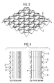
- one or more relatively rigid panel(s) 1 form a regular geometric pattern of truncated (open) or otherwise permeable outward-facing nodes 2 and pointed inward-facing anti-nodes 3 to grip into fibre-based dynamic insulation media 4.
- the dimensions are scalable and fabrication material choice wide, but the geometry of the support/encapsulation panels is very specific.
- a representative partial sample of a single panel is depicted in Fig. 1 and 2 .
- FIG. 3 this figure describes two possible embodiments of a core dynamic insulation element for a multitude of external wall, roof or floor types forming parts of the envelope of a breathing building or structure.
- Single and twin/mirrored panel(s) 1 encapsulating a layer(s) of dynamic insulation media 4 are shown in the 2-D schematics in Fig. 3 .
- core element (b) the truncated nodes 2 from a mirror pair of aligned encapsulating panels 1 provide the outward-facing openings through which air flows uniformly through the media 4, and inward-facing pairs of pointed anti-nodes 3 that grip the dynamic insulation without occluding the faces of the media. These anti-nodes have a pocket or hollowed configuration.
- shape of each cell pair 5 which acts as diffusion-contraction unit to enhance uniformity of the airflow entering the cell and passing through the media.
- Such cell pairs form a repeating structure that, together with the finite value of permeability of the media ensures good uniformity of flow through the core element, irrespective of what inlet/outlet conditions are imposed. Thus, where the air is introduced into the wall panel and/or where it is extracted from the panel would, in practice, have little or no detrimental effect on flow uniformity through the media.
- outdoor air is drawn into the cladding panel when the breathing building in which it is fitted is depressurised.
- the air queues up in the gap between the rainscreen and core cladding element (the inlet plenum), flows uniformly through the dynamic insulation media and thereafter fills the space behind the internal wall skin (the outlet plenum) before being dumped, preheated and filtered, into the room or air handling system.
- the inlet vent of the cladding panel in this particular case was located at the bottom, and the outlet vent at the top. This results in the very flat (less than 2% variation) velocity profile through the encapsulated dynamic insulation media shown in Fig. 6 .
- the particular geometry of the supporting/encapsulating panels that form part of the core dynamic insulation cladding element shown in Figs. 1 and 2 will henceforth be referred to as diamond lattice, since the planes forming this geometry have a diamond-shaped profile.
- the anti-nodes 3 are of a pyramidal form, with a point tapering to an octagonal base. Adjacent anti-nodes are connected at four of the eight sides of the octagonal base, with apertures 2 thereby being formed at the nodes between the anti-nodes in the lattice arrangement. In side view, the consequent profile is undulating, the panel as a whole resembling an apertured egg carton configuration.
- any desired size of breathing wall area and insulation thickness can be cut and manufactured from generic, standard-size panels, using a generic, thermally-isolating edge termination and sealing scheme such as that illustrated in 2-D in Fig. 7 .
- a edge termination and connection member 10 is shown between two panels.
- the edge termination and connection member has limbs 11 arranged in a cross formation, these limbs abut against similarly inclined elements of the panel 1 to thereby provide a secure and reliable seal between adjacent panels and their dynamic insulation.
- the edge termination and connection member may moreover be coupled to a wall external rainscreen 13 or an internal wall skin 14 through arms 12.
- Cross panel ducting 15 may also be provided in the edge termination and connection member.
- This feature enables a wide range of dynamic insulation cladding panel sizes and specifications to be achieved using a single generic panel type, and matching generic sealing/termination strip, with all the advantages that this brings from a manufacturing perspective. It also means that the core dynamic insulation element can be readily used in traditional and retrofit building projects as a straight, slot-in replacement for conventional insulation. Inlet and outlet plenums and vents through exterior envelope walls will naturally be required, and a means of depressurising the building to induce ventilation airflow found in order to achieve breathing building functionality.
- the inventors have hence developed an innovative support, packaging and air distribution system for fibre-based media that in CFD simulation has been shown to facilitate uniform airflow across a large area of dynamic insulation - i.e., a breathing wall.
- the system also enables effective edge sealing of the media to eliminate unwanted leakage, allows pre-fabrication of a range of modular breathing wall cladding panels, and permits the generic replacement of conventional insulation in most retrofit installations.
- cool ventilation air is drawn into a warm building through the breathing wall, air flows inwards in the opposite direction to the heat being conducted outwards as shown in the figure below.
- the dynamic U-value U d for a multi-layer envelope can be calculated from the total thermal resistance of the wall R s and the air flow through the wall v :
- U d v ⁇ ⁇ a ⁇ c a R s ⁇ exp v ⁇ ⁇ a ⁇ c a ⁇ R s - 1
- ⁇ a and c a are the density and specific heat capacity of air.
- Common air filtration media include membranes, foam-type cellular materials, pulps, and fibres.
- the latter represent an attractive choice for use in dynamically insulated buildings due to their excellent performance in the PM 2.5 - PM 10 range at low flow velocity, wide availability, utility, low cost, and prevalence (a PM 10 content is the suspended particulate matter in the air below 10 microns).
- Investigations reveal that potentially suitable natural and man-made fibre-types and products already exist and are used as conventional insulation media.
- a single-fibre model was used to derive efficiency. This was coupled with an iterative representation of clogging in fibrous filters. The model will be calibrated using data from experimental tests and field trials, to account for 3D effects, etc., to be reported in due course.
- ⁇ is the fibre density (packing fraction), d f the fibre diameter, and Z the insulation layer thickness.
- ⁇ f , J , l is the time-invariant single-fibre collection efficiency for layer J
- (1- ⁇ - ⁇ p , J , t 1+ k ) is the permeability of the layer.
- Two field test rigs to facilitate calibration of the filtration model, have been completed. They will be used to measure the cumulative pressure drop across dynamic insulation / filter media as particulate matter accumulates over a period 6 - 12 months for known variable loading.
- test rigs comprise a durable pipe housing with shielded intake and radial exhaust vents, filter media holder, axial extract fan, and low pressure transducer/data logger module.
- the insulation/filter media employed in the tests is VG4LWRO 4" oiled graduated glass, supplied by McLeod Russell. It has the following specifications - weight dry: 500-540 g/m 2 ; weight oiled: 640 g/m 2 ; fibre diameter: 25-30 microns; free thickness: 101.6mm ⁇ 6.3mm Compressed thickness 54mm ⁇ 3; The oil is chlorinated paraffin. Packing fraction was estimated for lab-measured permeance values [15]. The uncalibrated model was used to provide preliminary answers to the crucial questions of filtration efficiency over time and lifetime before clogging. A simple scenario, built around a small office suite in a polluted environment and its ventilation requirements, was developed and used to generate a set of results from the model. The results show the model behaving in a predictable manner, and very reassuring in terms of the filtration efficiency achievable and panel life before clogging occur.
- CIBSE guideline [191 indicate that 16 litres of air has to be provided per person per second in a smoking (i.e., worst case) environment.
- the test conditions are for 5 people in an office demanding a volumetric fresh air flow rate of 80 1/s through 10 m 2 of breathing wall area (the ventilation source).
- the resulting airflow velocity through the wall thus works out as 0.008 m/s.
- the definition of clogging was chosen as that point where the pressure drop required to provide acceptable levels of ventilation air exceeded 40 Pa (beyond which opening / closing doors becomes difficult).
- the simulated pollution imposed was for Marylebone Road in London, where the average yearly PM 10 level is 48 ⁇ g/m3, most of which is from incomplete combustion in motor vehicle engines.
- the density of the pollutant was assumed to be 1850 kg.m-3, at the top end of the pollutant spectrum. Temperature was taken to be 291K.
- the trial only part of which is reported here, was a 3-variable, 4-level full factorial design with no replication, resulting in a total of 64 sets of results.
- the effects of varying fibre diameter and packing fraction through depth were investigated for a graded insulation layer of thickness 100 mm, divided into 5 progressively denser slices of equal depth.
- the variables examined were fibre diameter (10 - 55 ⁇ ), initial packing fraction (0.008 - 0.011), and the corresponding packing fraction gradients (0.0035 - 0.002 per slice). For each time increment, the efficiency of each slice at filtering each particle diameter of pollutant was calculated. That pollutant not collected in the first slice was transferred to the next slice, etc. In this way, the efficiency of the entire layer was calculated.
- the present invention hence provides multi-function open or otherwise permeable panel(s) that provide structural support, or facilitates uniform airflow, edge termination, sealing, alignment, etc., or any combination thereof, for permeable media and in particular, but not solely restricted to, structurally weak (i.e., not self-supporting) dynamic insulation media.
- the multi-function panel(s) minimise occlusion of airflow through the inlet face of fibre-based dynamic insulation media to reduce the effective face area or degrade performance.
- the multi-function panel(s) seek to enable uniform airflow through a large breathing wall area to be achieved.
- the multi-function panel(s) further seek to enable effective in-room air movement and distribution in breathing buildings to be achieved easily and efficiently.
- the present invention further provides a revolutionary breathing wall cladding technology and multiplicity of modular cladding panel designs, including but not restricted to ventilated rainscreen designs, that uses fibre-based and other structurally weak dynamic insulation media, supported and/or encapsulated by the aforementioned multi-function panel(s) to achieve significant energy savings, air filtration and/or high indoor air quality.
- the present invention provides one or more multi-function panel(s) formed in a geometrical pattern of truncated (open) or otherwise permeable outward-facing nodes and pointed insulation-facing anti-nodes, as illustrated in Figs. 1 and 2 , to freely support and/or encapsulate fibre-based and/or any other structurally-weak dynamic insulation media.
- the present invention provides any number of multi-function panel(s) encapsulating a layer(s) of dynamic insulation media as shown in the 2-D schematics in Fig. 3 , henceforth referred to as core dynamic insulation elements.
- the present invention encompasses a core dynamic insulation element(s) as defined above, that may be used for a multiplicity of external wall, roof or floor types forming the envelope of a breathing building or structure, as well as a cladding panel or cladding system employing any core dynamic insulation element.
- the present invention further provides a ventilated rainscreen cladding panel design for dynamic insulation where outdoor air is drawn into the cladding panel when the building is depressurised, queues up in the gap between the rainscreen and core cladding element (the inlet plenum), flows uniformly through the dynamic insulation media and thereafter fills the space behind the internal wall skin (the outlet plenum) before being dumped, preheated and filtered, into the room or air handling system.
- a ventilated rainscreen cladding panel design for dynamic insulation where outdoor air is drawn into the cladding panel when the building is depressurised, queues up in the gap between the rainscreen and core cladding element (the inlet plenum), flows uniformly through the dynamic insulation media and thereafter fills the space behind the internal wall skin (the outlet plenum) before being dumped, preheated and filtered, into the room or air handling system.
- the present invention encompasses all variation(s) in geometry of multi-function panel(s) where truncated (open) nodes of any shape or form provide openings through which incoming and outgoing air can flow through the media, and anti-nodes grip the dynamic insulation media at opposing points without occluding the inlet and outlet faces of the media.
- the present invention further encompasses all variation(s) in geometry of multi-function panel(s), where the shape of a cell pair enables it to act as a diffusion-contraction unit, to assist in achieving uniformity of airflow entering the cell and passing through the media.
- the present invention further encompasses all variation(s) in geometry of multi-function panel(s) where cell pairs form a repeating structure that, together with the finite value of permeability of the media, ensure good uniformity of flow through the core dynamic insulation element irrespective of the inlet / outlet conditions imposed in practice.
- the present invention further encompasses specific pyramid-based geometry of multi-function open or otherwise permeable supporting/encapsulating panel(s), forming part of the core dynamic insulation cladding element shown in Figs. 1 and 2 , henceforth referred to as diamond lattice, after the planes forming this geometry which have a diamond-shaped profile
- the present invention encompasses all variation(s) in geometry of multi-function panel(s), for example using curved surfaces (i.e., cones instead of pyramids) to achieve similar functionality.
- the multi-function panel(s) may be arranged so that the cells of the lattice are uniformly arrayed along length and width dimensions, so that any desired size of breathing wall area and insulation thickness can be cut and manufactured from generic, standard-size panels, using a generic edge-termination and sealing scheme, such as that shown in Fig. 7 .
- the present invention further encompasses generic, thermally isolating (i.e., non-bridging) edge-termination and sealing method and components shown in Fig. 7 .
- the multi-function panel(s)of the present invention may be used to support/encapsulate one or more layer(s) of conventional or dynamic insulation media, filtration media, fluid-permeable media, structurally weak media, or any media, or any combination thereof.
- the multi-function panel(s) may be used to provide additional functionality through choice of constituent materials, or use of special coatings (e.g. TiO 2 as a NO x catalyst).
Landscapes
- Chemical & Material Sciences (AREA)
- Chemical Kinetics & Catalysis (AREA)
- Building Environments (AREA)
- Polishing Bodies And Polishing Tools (AREA)
- Rotary Pumps (AREA)
- Laminated Bodies (AREA)
Claims (29)
- Eine atmungsaktive, luftdurchlässige Wandplatte (1) für eine Zwischenverkleidungsschicht (4), die Filtereigenschaften aufweist, wobei die besagte atmungsaktive, luftdurchlässige Platte (1) Folgendes umfasst:-
Eine Vielzahl von Vorsprüngen (3), die in einer Gitterkonfiguration miteinander verbunden sind, wobei jeder der besagten Vorsprünge (3) einen Spitzenabschnitt aufweist und die betreffenden Spitzenabschnitte so angeordnet sind, dass sie in eine gemeinsame Richtung weisen, um bei der Anwendung eine formschlüssige Verbindung mit der Zwischenverkleidungsschicht (4) zu bilden, wobei jeder besagte Vorsprung (3) einen Basisrandbereich aufweist, an dem die angrenzenden Vorsprünge (3) miteinander verbunden sind,
die dadurch gekennzeichnet sind, dass die Basisrandbereiche miteinander verbunden sind, sodass die Öffnungen (2) zwischen den Basisrandbereichen in der Gitterkonfiguration abgegrenzt sind. - Eine luftdurchlässige Platte (1) gemäß Anspruch 1, worin die besagten Vorsprünge (3) die Form einer Pyramide haben.
- Eine luftdurchlässige Platte (1) gemäß Anspruch 1 oder 2, worin die besagten Vorsprünge (3) als ein ausgehöhltes Element vorhanden sind.
- Eine luftdurchlässige Platte (1) gemäß einem der vorhergehenden Ansprüche, worin die Vorsprünge (3) entsprechend gestaltet sind, damit sie nur begrenzt in die Zwischenverkleidungsschicht (4) eindringen können.
- Eine luftdurchlässige Platte (1) gemäß Anspruch 4, worin die Querschnittsfläche jedes Vorsprungs (3) sich vom Spitzenabschnitt entlang seiner Längsachse vergrößert.
- Eine luftdurchlässige Platte (1) gemäß Anspruch 3, worin die Platte (1) aus einem einzelnen Stück gepresst ist.
- Eine luftdurchlässige Platte (1) gemäß Anspruch 3, worin die Platte (1) aus einem Plastikmaterial geformt ist.
- Eine luftdurchlässige Platte (1) gemäß einem der Ansprüche 6 oder 7, worin die Platte (1) aus feuerhemmenden Materialien geformt ist.
- Eine luftdurchlässige Platte (1) gemäß einem der Ansprüche 6 bis 8, worin die Öffnungen (2) bei Verwendung mit der Platte (1) an der oder angrenzend an die Zwischenschicht (4) ein Loch mit sich ausdehnendem Volumen auf die Zwischenschicht (4) darstellen.
- Ein Verkleidungssystem für Gebäude, das Folgendes beinhaltet:eine Zwischenverkleidungsschicht (4), die Filtereigenschaften besitzt; undeine luftdurchlässige Platte (1) zur Abstützung der Zwischenverkleidungsschicht (4), wobei die besagte luftdurchlässige Platte (1) eine Vielzahl von Vorsprüngen (3) aufweist, die in einer Gitterkonfiguration miteinander verbunden sind und jeder der besagten Vorsprünge (3) einen Spitzenabschnitt aufweist; die betreffenden Spitzenabschnitte sind so angeordnet, dass sie in eine gemeinsame Richtung weisen, um eine formschlüssige Verbindung mit der Zwischenverkleidungsschicht (4) zu bilden, wobei jeder besagte Teil (3) einen Basisrandbereich hat, an dem die angrenzenden Vorsprünge (3) miteinander verbunden sind,die dadurch gekennzeichnet sind, dass die Basisrandbereiche miteinander verbunden sind, sodass die Öffnungen (2) zwischen den Basisrandbereichen in der Gitterkonfiguration abgegrenzt sind.
- Ein Verkleidungssystem für Gebäude gemäß Anspruch 10, worin die Vorsprünge (3) als ein ausgehöhltes Element vorhanden sind.
- Ein Verkleidungssystem für Gebäude gemäß Anspruch 11, worin die Zwischenverkleidungsschicht (4) ein abgestuftes Filterprofil aufweist.
- Ein Verkleidungssystem für Gebäude gemäß Anspruch 12, worin die Filtereigenschaften der Zwischenverkleidungsschicht (4) derart beschaffen sind, dass sie relativ große Partikel in Richtung einer Außenfläche davon und verhältnismäßig kleinere Partikel in Richtung einer Innenfläche davon abfangen.
- Ein Verkleidungssystem für Gebäude gemäß einem der Ansprüche 11 bis 13 worin die Zwischenverkleidungsschicht (4) thermische und/oder schalldämmende Eigenschaften hat.
- Ein Verkleidungssystem für Gebäude gemäß einem der Ansprüche 11 bis 14, worin die Zwischenverkleidungsschicht (4) aus einem oder mehreren der folgenden Materialien besteht: Mineralwolle, nass geblasene Zellulose und Glaswolle.
- Ein Verkleidungssystem für Gebäude gemäß einem der Ansprüche 11 bis 15, worin die Zwischenverkleidungsschicht (4) in einer oder mehreren der folgenden Formen vorhanden ist:- Membrane, Fasern, Zellstoff- oder zelluläre (Schaum oder Schwamm) Materialien oder modifizierter Leichtbeton.
- Ein Verkleidungssystem für Gebäude gemäß einem der Ansprüche 11 bis 16, worin die Zwischenverkleidungsschicht (4) Filtermaterialien für eine oder mehrere der Folgenden beinhaltet:- Feinstaubemissionen, Schadgase, chemische Stoffe und biologische Stoffe.
- Ein Verkleidungssystem für Gebäude gemäß einem der Ansprüche 11 bis 17, worin die Zwischenverkleidungsschicht (4) in der Form von Platteneinheiten zur Verfügung steht.
- Ein Verkleidungssystem für Gebäude gemäß Anspruch 18, worin die Platteneinheiten im Modulformat zur Verfügung stehen.
- Ein Verkleidungssystem für Gebäude gemäß einem der Ansprüche 11 bis 19, worin die Zwischenverkleidungsschicht (4) aus einer Vielzahl von einer oder mehreren getrennten Filterschichten gebildet wird, die unterschiedliche Filtereigenschaften aufweisen.
- Ein Verkleidungssystem für Gebäude gemäß einem der Ansprüche 11 bis 20, worin die Zwischenverkleidungsschicht (4) entsprechend ausgewählt wird, um eine bestimmte Bandbreite von Partikelgrößen, Schadgasen, chemischen Schadstoffen und/oder biologischen Stoffen zu entfernen.
- Ein Verkleidungssystem für Gebäude gemäß Anspruch 21, worin die getrennten Filterschichten der Zwischenverkleidungsschicht (4) gemeinsam weitgehend das komplette Filterspektrum für Feinstaub- und sonstigen Verschmutzung abdecken.
- Ein Verkleidungssystem für Gebäude gemäß einem der Ansprüche 20 bis 22, worin die oder jede Filterschicht der Zwischenverkleidungsschicht (4) unabhängig voneinander austauschbar ist.
- Ein Verkleidungssystem für Gebäude gemäß einem der Ansprüche 20 bis 23, worin die oder jede Filterschicht der Zwischenverkleidungsschicht (4) ein oder mehrere Einwegfilterelemente enthält.
- Ein Verkleidungssystem für Gebäude gemäß einem der Ansprüche 11 bis 23, das überdies eine zweite luftdurchlässige Platte (1) enthält, worin die besagten luftdurchlässigen Platten (1) sich auf beiden Stirnseiten der besagten Zwischenverkleidungsschicht befinden.
- Ein Verkleidungssystem für Gebäude gemäß einem der Ansprüche 11 bis 25, das überdies ein Wandteil (14) umfasst, welches an die Platte (1) angrenzt und damit verbunden ist.
- Ein Verkleidungssystem für Gebäude gemäß Anspruch 26, das interne (14) und externe (13) Wandteile umfasst, innerhalb derer sich die Platte (1) und die Zwischenverkleidungsschicht (4) befinden.
- Ein Verkleidungssystem für Gebäude gemäß Anspruch 26 oder 27, das überdies ein oder mehrere Kantenteile (10) umfasst, die so gestaltet sind, dass sie sich mit den angrenzenden Schichten der Zwischenverkleidung (4) verbinden.
- Ein Verkleidungssystem für Gebäude gemäß Anspruch 27, worin die Kantenteile (10) Schenkel (11) aufweisen, die in einer Kreuzform angeordnet sind, wobei die Schenkel (11) ähnlich zu den Oberflächen der Vorsprünge (3) auf den angrenzenden Platten (1) hin geneigt sind, um an diese anzustoßen.
Applications Claiming Priority (3)
| Application Number | Priority Date | Filing Date | Title |
|---|---|---|---|
| GB0322166A GB0322166D0 (en) | 2003-09-22 | 2003-09-22 | Cladding |
| GB0322659A GB0322659D0 (en) | 2003-09-26 | 2003-09-26 | Support panel |
| PCT/GB2004/004023 WO2005028076A1 (en) | 2003-09-22 | 2004-09-22 | Support panel |
Publications (2)
| Publication Number | Publication Date |
|---|---|
| EP1675669A1 EP1675669A1 (de) | 2006-07-05 |
| EP1675669B1 true EP1675669B1 (de) | 2010-07-14 |
Family
ID=34379493
Family Applications (1)
| Application Number | Title | Priority Date | Filing Date |
|---|---|---|---|
| EP04768567A Expired - Lifetime EP1675669B1 (de) | 2003-09-22 | 2004-09-22 | Traegerplatte |
Country Status (5)
| Country | Link |
|---|---|
| US (1) | US20070033891A1 (de) |
| EP (1) | EP1675669B1 (de) |
| AT (1) | ATE473794T1 (de) |
| DE (1) | DE602004028142D1 (de) |
| WO (1) | WO2005028076A1 (de) |
Families Citing this family (13)
| Publication number | Priority date | Publication date | Assignee | Title |
|---|---|---|---|---|
| US8381471B2 (en) * | 2005-12-09 | 2013-02-26 | Stephen C. Kobre | Packaging/construction material to make variable sized structures with intrinsic cushioning |
| US8769901B2 (en) | 2010-05-28 | 2014-07-08 | The Diller Corporation | Cladding system for building laminates |
| US11097512B1 (en) * | 2020-01-31 | 2021-08-24 | Champion Link Intern Aiton Al Corporation | Floor panel and method of manufacturing a floor panel |
| US11718565B2 (en) | 2020-01-31 | 2023-08-08 | Champion Link International Corporation | Panel for forming a floor covering and such floor covering |
| US11053696B1 (en) * | 2020-01-31 | 2021-07-06 | Champion Link International Corporation | Panel for forming a floor covering and such floor covering |
| US11927020B2 (en) | 2020-01-31 | 2024-03-12 | Champion Link International Corporation | Floor panel and method of manufacturing a floor panel |
| US12194404B2 (en) * | 2020-02-05 | 2025-01-14 | University Of Southern California | Cooling and smog filtering building facade panel |
| US11542712B2 (en) | 2020-03-13 | 2023-01-03 | Champion Link International Corporation | Panel and method of producing a panel |
| US11149441B2 (en) | 2020-03-13 | 2021-10-19 | Champion Link International Corporation | Panel and method of producing a panel |
| US11724537B2 (en) | 2020-05-26 | 2023-08-15 | Champion Link International Corporation | Panel and method for producing a panel |
| NL2025684B1 (en) | 2020-05-26 | 2021-12-14 | Champion Link Int Corp | Panel and method for producing a panel |
| US11530536B2 (en) | 2020-07-15 | 2022-12-20 | Champion Link International Corporation | Panel |
| US11326356B2 (en) | 2020-07-15 | 2022-05-10 | Champion Link International Corporation | Floor or wall panel |
Family Cites Families (21)
| Publication number | Priority date | Publication date | Assignee | Title |
|---|---|---|---|---|
| US55930A (en) * | 1866-06-26 | Improvement in horse-rakes | ||
| US1875188A (en) * | 1932-01-27 | 1932-08-30 | Sherman Products Corp | Unit formed of sheet material |
| US2150997A (en) * | 1933-02-01 | 1939-03-21 | Nat Gypsum Co | Wall surfacing unit |
| US2264961A (en) * | 1937-06-21 | 1941-12-02 | Wood Conversion Co | Thermal insulation structure |
| US2150338A (en) * | 1937-08-09 | 1939-03-14 | Charles L Newport | Perforate wall |
| US2293351A (en) * | 1939-12-16 | 1942-08-18 | Celotex Corp | Sound absorbing construction |
| US2847086A (en) * | 1953-08-04 | 1958-08-12 | Muller Paul Adolf | Filtering material |
| US3217455A (en) * | 1964-09-28 | 1965-11-16 | Joseph H Burges | Building construction of modular panels |
| US3763633A (en) * | 1971-02-09 | 1973-10-09 | C Soltis | Electrostatic air filter |
| CA975918A (en) * | 1973-03-27 | 1975-10-14 | Skapti J. Borgford | Shear form structure |
| US4004897A (en) * | 1974-08-28 | 1977-01-25 | Squires Arthur M | Filtering dusty gas in improved panel bed |
| NL7714437A (nl) * | 1977-12-27 | 1979-06-29 | Leer Koninklijke Emballage | Constructie-element. |
| DE3733285C2 (de) * | 1987-10-02 | 1994-02-10 | Helmut Pelzer | Verkleidung von schallabsorbierenden Einbauteilen und Vorrichtung zu deren Herstellung |
| US4894275A (en) * | 1987-10-02 | 1990-01-16 | Helmut Pelzer | Floor mat/foot pad for automobiles |
| US4931346A (en) * | 1988-12-19 | 1990-06-05 | Book Covers Inc. | Lightweight laminated paperboard |
| US5028474A (en) * | 1989-07-25 | 1991-07-02 | Czaplicki Ronald M | Cellular core structure providing gridlike bearing surfaces on opposing parallel planes of the formed core |
| JP2522604B2 (ja) * | 1990-04-26 | 1996-08-07 | 株式会社ユニックス | 吸音材およびその製造方法 |
| WO1996000823A1 (en) * | 1994-06-28 | 1996-01-11 | Skanska Teknik Ab | Heat-insulating outer wall for a building |
| US6585793B2 (en) * | 2000-12-29 | 2003-07-01 | Andreae Filters, Inc. | Filter apparatus and methods |
| DE10221694B4 (de) * | 2002-05-16 | 2018-07-12 | Branofilter Gmbh | Mehrlagiger Filteraufbau, Verwendung eines solchen mehrlagigen Filteraufbaus, Staubfilterbeutel, Taschenfilterbeutel, plissierter Filter, flächiger Abluftfilter und Luftfilter für Kraftfahrzeuge |
| US6966402B2 (en) * | 2003-06-02 | 2005-11-22 | Dana Corporation | Acoustical heat shield |
-
2004
- 2004-09-22 EP EP04768567A patent/EP1675669B1/de not_active Expired - Lifetime
- 2004-09-22 WO PCT/GB2004/004023 patent/WO2005028076A1/en not_active Ceased
- 2004-09-22 AT AT04768567T patent/ATE473794T1/de not_active IP Right Cessation
- 2004-09-22 US US10/572,851 patent/US20070033891A1/en not_active Abandoned
- 2004-09-22 DE DE602004028142T patent/DE602004028142D1/de not_active Expired - Lifetime
Also Published As
| Publication number | Publication date |
|---|---|
| WO2005028076A1 (en) | 2005-03-31 |
| US20070033891A1 (en) | 2007-02-15 |
| EP1675669A1 (de) | 2006-07-05 |
| ATE473794T1 (de) | 2010-07-15 |
| DE602004028142D1 (de) | 2010-08-26 |
Similar Documents
| Publication | Publication Date | Title |
|---|---|---|
| EP1675669B1 (de) | Traegerplatte | |
| US8029591B2 (en) | Inorganic fiber aggregate, method for manufacturing inorganic fiber aggregate, honeycomb structure, method for manufacturing honeycomb structure, and exhaust gas purifier | |
| US7455710B2 (en) | Honeycomb structure and method of manufacturing the same | |
| US7441586B2 (en) | Heat exchange apparatus and ventilation system using the same | |
| WO1999060307A1 (en) | Integrated heat recovery ventilator hepa filter using a hepa filter material regenerative heat exchanger | |
| EP0697051A1 (de) | Unterdecke | |
| JP2011206760A (ja) | フィルタバンク内に音減衰器を統合する方法及びシステム | |
| Imbabi et al. | Smart breathing walls for integrated ventilation, heat exchange, energy efficiency and air filtration | |
| US4604869A (en) | Porous ceramic structure | |
| EP1467858B1 (de) | Luftdurchlässiges fassadenelement | |
| US20160236210A1 (en) | System and method for air filtration via cyclone separators enclosed within exterior walls | |
| JPH07253029A (ja) | ガスタービン吸気用高性能フィルタ及びそれを用いたガスタービン吸気用フィルタユニット | |
| CN101247875A (zh) | 蜂窝结构体、蜂窝结构体的制造方法和废气净化装置 | |
| CN110260414A (zh) | 一种可移动室内空调 | |
| CN212029833U (zh) | 基于物联网控制的全热交换机 | |
| CN206919313U (zh) | 节能的空调器的智能调节新风系统 | |
| WO1994024382A1 (de) | Unterdecke | |
| JP2003126625A (ja) | 平行流型エアフィルタ | |
| CN207179948U (zh) | 中央式热回收机组 | |
| JP2009226243A (ja) | 除塵装置 | |
| JP2002126432A (ja) | エアフィルタ用セパレータおよびエアフィルタ | |
| CN223965545U (zh) | 一种窗式通风系统 | |
| WO2007054952A2 (en) | Pleated filter with isokinetic spacers | |
| CN117627190A (zh) | 一种岩棉条复合板及建筑外墙保温系统 | |
| CN209279319U (zh) | 空气净化器 |
Legal Events
| Date | Code | Title | Description |
|---|---|---|---|
| PUAI | Public reference made under article 153(3) epc to a published international application that has entered the european phase |
Free format text: ORIGINAL CODE: 0009012 |
|
| 17P | Request for examination filed |
Effective date: 20060424 |
|
| AK | Designated contracting states |
Kind code of ref document: A1 Designated state(s): AT BE BG CH CY CZ DE DK EE ES FI FR GB GR HU IE IT LI LU MC NL PL PT RO SE SI SK TR |
|
| DAX | Request for extension of the european patent (deleted) | ||
| 17Q | First examination report despatched |
Effective date: 20090427 |
|
| GRAP | Despatch of communication of intention to grant a patent |
Free format text: ORIGINAL CODE: EPIDOSNIGR1 |
|
| RIN1 | Information on inventor provided before grant (corrected) |
Inventor name: IMBABI, M. S-E.,THE UNIV. OF ABERDEEN |
|
| GRAS | Grant fee paid |
Free format text: ORIGINAL CODE: EPIDOSNIGR3 |
|
| RAP1 | Party data changed (applicant data changed or rights of an application transferred) |
Owner name: ENVIROMENTAL BUILDING PARTNERSHIP LIMITED |
|
| GRAA | (expected) grant |
Free format text: ORIGINAL CODE: 0009210 |
|
| AK | Designated contracting states |
Kind code of ref document: B1 Designated state(s): AT BE BG CH CY CZ DE DK EE ES FI FR GB GR HU IE IT LI LU MC NL PL PT RO SE SI SK TR |
|
| REG | Reference to a national code |
Ref country code: GB Ref legal event code: FG4D |
|
| REG | Reference to a national code |
Ref country code: CH Ref legal event code: EP |
|
| REG | Reference to a national code |
Ref country code: IE Ref legal event code: FG4D |
|
| REF | Corresponds to: |
Ref document number: 602004028142 Country of ref document: DE Date of ref document: 20100826 Kind code of ref document: P |
|
| REG | Reference to a national code |
Ref country code: NL Ref legal event code: VDEP Effective date: 20100714 |
|
| PG25 | Lapsed in a contracting state [announced via postgrant information from national office to epo] |
Ref country code: FI Free format text: LAPSE BECAUSE OF FAILURE TO SUBMIT A TRANSLATION OF THE DESCRIPTION OR TO PAY THE FEE WITHIN THE PRESCRIBED TIME-LIMIT Effective date: 20100714 Ref country code: NL Free format text: LAPSE BECAUSE OF FAILURE TO SUBMIT A TRANSLATION OF THE DESCRIPTION OR TO PAY THE FEE WITHIN THE PRESCRIBED TIME-LIMIT Effective date: 20100714 Ref country code: AT Free format text: LAPSE BECAUSE OF FAILURE TO SUBMIT A TRANSLATION OF THE DESCRIPTION OR TO PAY THE FEE WITHIN THE PRESCRIBED TIME-LIMIT Effective date: 20100714 |
|
| PGFP | Annual fee paid to national office [announced via postgrant information from national office to epo] |
Ref country code: FR Payment date: 20101130 Year of fee payment: 7 |
|
| PG25 | Lapsed in a contracting state [announced via postgrant information from national office to epo] |
Ref country code: PT Free format text: LAPSE BECAUSE OF FAILURE TO SUBMIT A TRANSLATION OF THE DESCRIPTION OR TO PAY THE FEE WITHIN THE PRESCRIBED TIME-LIMIT Effective date: 20101115 Ref country code: CY Free format text: LAPSE BECAUSE OF FAILURE TO SUBMIT A TRANSLATION OF THE DESCRIPTION OR TO PAY THE FEE WITHIN THE PRESCRIBED TIME-LIMIT Effective date: 20100714 Ref country code: SI Free format text: LAPSE BECAUSE OF FAILURE TO SUBMIT A TRANSLATION OF THE DESCRIPTION OR TO PAY THE FEE WITHIN THE PRESCRIBED TIME-LIMIT Effective date: 20100714 Ref country code: BG Free format text: LAPSE BECAUSE OF FAILURE TO SUBMIT A TRANSLATION OF THE DESCRIPTION OR TO PAY THE FEE WITHIN THE PRESCRIBED TIME-LIMIT Effective date: 20101014 Ref country code: PL Free format text: LAPSE BECAUSE OF FAILURE TO SUBMIT A TRANSLATION OF THE DESCRIPTION OR TO PAY THE FEE WITHIN THE PRESCRIBED TIME-LIMIT Effective date: 20100714 |
|
| PGFP | Annual fee paid to national office [announced via postgrant information from national office to epo] |
Ref country code: DE Payment date: 20101014 Year of fee payment: 7 |
|
| PG25 | Lapsed in a contracting state [announced via postgrant information from national office to epo] |
Ref country code: BE Free format text: LAPSE BECAUSE OF FAILURE TO SUBMIT A TRANSLATION OF THE DESCRIPTION OR TO PAY THE FEE WITHIN THE PRESCRIBED TIME-LIMIT Effective date: 20100714 Ref country code: SE Free format text: LAPSE BECAUSE OF FAILURE TO SUBMIT A TRANSLATION OF THE DESCRIPTION OR TO PAY THE FEE WITHIN THE PRESCRIBED TIME-LIMIT Effective date: 20100714 Ref country code: GR Free format text: LAPSE BECAUSE OF FAILURE TO SUBMIT A TRANSLATION OF THE DESCRIPTION OR TO PAY THE FEE WITHIN THE PRESCRIBED TIME-LIMIT Effective date: 20101015 |
|
| PGFP | Annual fee paid to national office [announced via postgrant information from national office to epo] |
Ref country code: GB Payment date: 20101014 Year of fee payment: 7 |
|
| PG25 | Lapsed in a contracting state [announced via postgrant information from national office to epo] |
Ref country code: DK Free format text: LAPSE BECAUSE OF FAILURE TO SUBMIT A TRANSLATION OF THE DESCRIPTION OR TO PAY THE FEE WITHIN THE PRESCRIBED TIME-LIMIT Effective date: 20100714 Ref country code: MC Free format text: LAPSE BECAUSE OF NON-PAYMENT OF DUE FEES Effective date: 20100930 |
|
| REG | Reference to a national code |
Ref country code: CH Ref legal event code: PL |
|
| PLBE | No opposition filed within time limit |
Free format text: ORIGINAL CODE: 0009261 |
|
| STAA | Information on the status of an ep patent application or granted ep patent |
Free format text: STATUS: NO OPPOSITION FILED WITHIN TIME LIMIT |
|
| PG25 | Lapsed in a contracting state [announced via postgrant information from national office to epo] |
Ref country code: SK Free format text: LAPSE BECAUSE OF FAILURE TO SUBMIT A TRANSLATION OF THE DESCRIPTION OR TO PAY THE FEE WITHIN THE PRESCRIBED TIME-LIMIT Effective date: 20100714 Ref country code: RO Free format text: LAPSE BECAUSE OF FAILURE TO SUBMIT A TRANSLATION OF THE DESCRIPTION OR TO PAY THE FEE WITHIN THE PRESCRIBED TIME-LIMIT Effective date: 20100714 Ref country code: IT Free format text: LAPSE BECAUSE OF FAILURE TO SUBMIT A TRANSLATION OF THE DESCRIPTION OR TO PAY THE FEE WITHIN THE PRESCRIBED TIME-LIMIT Effective date: 20100714 Ref country code: CZ Free format text: LAPSE BECAUSE OF FAILURE TO SUBMIT A TRANSLATION OF THE DESCRIPTION OR TO PAY THE FEE WITHIN THE PRESCRIBED TIME-LIMIT Effective date: 20100714 Ref country code: EE Free format text: LAPSE BECAUSE OF FAILURE TO SUBMIT A TRANSLATION OF THE DESCRIPTION OR TO PAY THE FEE WITHIN THE PRESCRIBED TIME-LIMIT Effective date: 20100714 |
|
| 26N | No opposition filed |
Effective date: 20110415 |
|
| PG25 | Lapsed in a contracting state [announced via postgrant information from national office to epo] |
Ref country code: ES Free format text: LAPSE BECAUSE OF FAILURE TO SUBMIT A TRANSLATION OF THE DESCRIPTION OR TO PAY THE FEE WITHIN THE PRESCRIBED TIME-LIMIT Effective date: 20101025 |
|
| REG | Reference to a national code |
Ref country code: DE Ref legal event code: R097 Ref document number: 602004028142 Country of ref document: DE Effective date: 20110415 |
|
| PG25 | Lapsed in a contracting state [announced via postgrant information from national office to epo] |
Ref country code: CH Free format text: LAPSE BECAUSE OF NON-PAYMENT OF DUE FEES Effective date: 20100930 Ref country code: IE Free format text: LAPSE BECAUSE OF NON-PAYMENT OF DUE FEES Effective date: 20100922 Ref country code: LI Free format text: LAPSE BECAUSE OF NON-PAYMENT OF DUE FEES Effective date: 20100930 |
|
| GBPC | Gb: european patent ceased through non-payment of renewal fee |
Effective date: 20110922 |
|
| REG | Reference to a national code |
Ref country code: FR Ref legal event code: ST Effective date: 20120531 |
|
| REG | Reference to a national code |
Ref country code: DE Ref legal event code: R119 Ref document number: 602004028142 Country of ref document: DE Effective date: 20120403 |
|
| PG25 | Lapsed in a contracting state [announced via postgrant information from national office to epo] |
Ref country code: DE Free format text: LAPSE BECAUSE OF NON-PAYMENT OF DUE FEES Effective date: 20120403 |
|
| PG25 | Lapsed in a contracting state [announced via postgrant information from national office to epo] |
Ref country code: GB Free format text: LAPSE BECAUSE OF NON-PAYMENT OF DUE FEES Effective date: 20110922 Ref country code: FR Free format text: LAPSE BECAUSE OF NON-PAYMENT OF DUE FEES Effective date: 20110930 |
|
| PG25 | Lapsed in a contracting state [announced via postgrant information from national office to epo] |
Ref country code: LU Free format text: LAPSE BECAUSE OF NON-PAYMENT OF DUE FEES Effective date: 20100922 Ref country code: HU Free format text: LAPSE BECAUSE OF FAILURE TO SUBMIT A TRANSLATION OF THE DESCRIPTION OR TO PAY THE FEE WITHIN THE PRESCRIBED TIME-LIMIT Effective date: 20110115 |
|
| PG25 | Lapsed in a contracting state [announced via postgrant information from national office to epo] |
Ref country code: TR Free format text: LAPSE BECAUSE OF FAILURE TO SUBMIT A TRANSLATION OF THE DESCRIPTION OR TO PAY THE FEE WITHIN THE PRESCRIBED TIME-LIMIT Effective date: 20100714 |