EP1675251A1 - Tube motor for window blinds - Google Patents
Tube motor for window blinds Download PDFInfo
- Publication number
- EP1675251A1 EP1675251A1 EP05026432A EP05026432A EP1675251A1 EP 1675251 A1 EP1675251 A1 EP 1675251A1 EP 05026432 A EP05026432 A EP 05026432A EP 05026432 A EP05026432 A EP 05026432A EP 1675251 A1 EP1675251 A1 EP 1675251A1
- Authority
- EP
- European Patent Office
- Prior art keywords
- motor
- drive device
- rotor
- stator
- transverse flux
- Prior art date
- Legal status (The legal status is an assumption and is not a legal conclusion. Google has not performed a legal analysis and makes no representation as to the accuracy of the status listed.)
- Granted
Links
Images

Classifications
-
- H—ELECTRICITY
- H02—GENERATION; CONVERSION OR DISTRIBUTION OF ELECTRIC POWER
- H02K—DYNAMO-ELECTRIC MACHINES
- H02K21/00—Synchronous motors having permanent magnets; Synchronous generators having permanent magnets
- H02K21/12—Synchronous motors having permanent magnets; Synchronous generators having permanent magnets with stationary armatures and rotating magnets
- H02K21/22—Synchronous motors having permanent magnets; Synchronous generators having permanent magnets with stationary armatures and rotating magnets with magnets rotating around the armatures, e.g. flywheel magnetos
- H02K21/227—Synchronous motors having permanent magnets; Synchronous generators having permanent magnets with stationary armatures and rotating magnets with magnets rotating around the armatures, e.g. flywheel magnetos having an annular armature coil
-
- E—FIXED CONSTRUCTIONS
- E06—DOORS, WINDOWS, SHUTTERS, OR ROLLER BLINDS IN GENERAL; LADDERS
- E06B—FIXED OR MOVABLE CLOSURES FOR OPENINGS IN BUILDINGS, VEHICLES, FENCES OR LIKE ENCLOSURES IN GENERAL, e.g. DOORS, WINDOWS, BLINDS, GATES
- E06B9/00—Screening or protective devices for wall or similar openings, with or without operating or securing mechanisms; Closures of similar construction
- E06B9/56—Operating, guiding or securing devices or arrangements for roll-type closures; Spring drums; Tape drums; Counterweighting arrangements therefor
- E06B9/68—Operating devices or mechanisms, e.g. with electric drive
- E06B9/72—Operating devices or mechanisms, e.g. with electric drive comprising an electric motor positioned inside the roller
-
- H—ELECTRICITY
- H02—GENERATION; CONVERSION OR DISTRIBUTION OF ELECTRIC POWER
- H02K—DYNAMO-ELECTRIC MACHINES
- H02K21/00—Synchronous motors having permanent magnets; Synchronous generators having permanent magnets
- H02K21/12—Synchronous motors having permanent magnets; Synchronous generators having permanent magnets with stationary armatures and rotating magnets
- H02K21/22—Synchronous motors having permanent magnets; Synchronous generators having permanent magnets with stationary armatures and rotating magnets with magnets rotating around the armatures, e.g. flywheel magnetos
-
- H—ELECTRICITY
- H02—GENERATION; CONVERSION OR DISTRIBUTION OF ELECTRIC POWER
- H02K—DYNAMO-ELECTRIC MACHINES
- H02K7/00—Arrangements for handling mechanical energy structurally associated with dynamo-electric machines, e.g. structural association with mechanical driving motors or auxiliary dynamo-electric machines
- H02K7/14—Structural association with mechanical loads, e.g. with hand-held machine tools or fans
-
- H—ELECTRICITY
- H02—GENERATION; CONVERSION OR DISTRIBUTION OF ELECTRIC POWER
- H02K—DYNAMO-ELECTRIC MACHINES
- H02K16/00—Machines with more than one rotor or stator
Definitions
- the invention relates to a drive device according to the preamble of claim 1.
- Such drive devices are generally widely known. They work with electric current and have a stator wound with a coil arrangement and a rotor connected to the drive shaft. In many cases, the rotors have a coil arrangement, and the rotors are provided with slip rings and carbon pencils for supplying the rotor current, or the motors are designed as asynchronous motors.
- the drive device comprises in addition to the actual engine nor a Endabschaltech, a brake and a multi-stage planetary gear. With these drive devices, the torques required for blinds, awnings, shutters and the like can only be achieved by means of a high reduction ratio (> approximately 1: 100) having the transmission. at Single-phase capacitor motors, a speed control is also hardly possible. The speed of the drive devices is not constant, but load-dependent. Furthermore, the production of these drive devices is quite complicated and thus costly.
- transversal flux motors designed as an internal rotor with a stator which has an annular stator coil with a central axis and in which the stator coil is surrounded along its circumference by at least approximately C-shaped stator lamination stacks.
- adjacent C-shaped stator lamination packages are directed alternately with the free ends of their legs radially inwardly and outwardly.
- the stator laminations are oriented at least in sections substantially tangentially to the center axis of the stator coil or to the circumference of the stator coil.
- the motor further comprises a rotor of a carrier connected to the drive shaft and at least one ring attached to the carrier of alternating magnetic poles, which face the legs of each adjacent stator lamination.
- a transverse flux motor can be used to produce very compact, low-speed motors with very high efficiency and high power in a simple manner.
- a transverse flux motor is known, which is formed with an external rotor and provided with a rotor having permanent magnets.
- multi-phase motors wherein at least one Genzousetrennteil is used, are attached to the stator on both sides, each with a coil assembly.
- the illustrated embodiments are also not suitable, because the external rotor are connected via a Ringerhemperetcmit the motor shaft and therefore the motor does not have the necessary compactness for a tubular motor.
- WO 99/48190 A1 discloses, for example, a transverse flux motor with C-shaped magnetic flux yokes which additionally have I-shaped magnetic flux yokes at the air gap.
- EP 0 218 522 discloses a transverse flux motor which likewise has C-shaped magnetic flux yokes and, additionally, magnetic flux conducting pieces arranged in axial rows. The latter are at least partially aligned with permanent magnet elements of the rotor.
- the air gap is axial.
- transverse flux motors are used in particular in the automotive industry or in machine tools and are not intended for use in tubular motors for blinds, awnings, shutters and the like.
- the invention has for its object to provide a drive device referred to in the preamble of claim 1, which is more suitable for blinds, awnings, shutters and the like.
- the drive device according to the invention can be assembled in a confined space, as desired for the application, while working highly efficiently at high power density.
- the compact design increases the efficiency of the engine.
- the torque-dependent losses can be reduced become.
- the coils are concentric around the motor axis, which can therefore be easily manufactured.
- the tubular motor may comprise two or more single-phase motor parts, which are preferably formed substantially the same.
- the motor part used for a single-stage motor can be used multiple times as a basic module in multi-stage motors, so that drive devices higher power can be produced inexpensively.
- a further embodiment of the invention provides that the transverse flux motor is divided into a first motor part and a second motor part in that between the motor parts as part of the motor housing, a radially extending, provided with a central opening for the motor shaft separator, on both end sides each wound with a coil assembly stator is fixed, and on both sides of the separating part in each case a cross-sectionally C-shaped, provided on the motor shaft with its inner tube and the separating part opening rotor part is provided.
- a simple construction of the tubular motor is achieved.
- the inner tube of the rotor part is partially received in the central opening.
- the inner tube of the rotor part slides in the central opening.
- the motor shaft is supported by it.
- controls for the engine are housed in an end portion of the motor housing. These controls are mainly used for the end stop and the engine control and are operated electronically.
- the drive device can be operated directly by the mains voltage or alternatively with a low voltage.
- the motor is mechanically locked in the de-energized state for holding the load.
- conventional positive, frictional or non-positive locking devices such as those operating according to the Schlinfeder principle, solenoid principle or the like can be used.
- an electric drive device 1 is shown as it comes as a tubular motor in winding tubes of blinds, awnings, shutters and the like used.
- the drive device is equipped with a tubular housing 2, which has a first motor part 3, a second motor part 4 and a control part 5.
- the two motor parts 3 and 4 form a two-stage transversal flux motor, while the control part 5 accommodates the electronic controls required for the end shutdown and the control of the transverse flux motor, which are not described in detail.
- the housing 2 is are not described in detail.
- the housing 2 is provided with four screw feet, such as the screw feet 6-8.
- a motor shaft 9 is mounted at both end regions by means of ball bearings.
- the ends of the motor shaft 9 are each closed with a coupling piece 10 and 11 respectively.
- the motor housing 2 includes a housing cover 12, a middle first separating part 13 and a second separating part 14, all of which extend radially and are each provided with a central opening 15 or 16 or 17.
- the motor shaft 9 extends through the central openings 15-17.
- the transverse flux motor is divided into the two motor parts 3 and 4.
- stator sections 18, 19, each with a coil arrangement are fastened in the form of cylinders to both end faces in a manner not shown. These stator parts carry distributed over its circumference, not shown Flussleit Publishede in adjacent rows over the length of the stator.
- a cross-sectionally U-shaped first rotor part 20 with an inner tube 21 and an outer tube 22 is arranged between the housing cover 12 and the separating part 13.
- the inner tube 21 is mounted on the motor shaft 9, wherein it partially protrudes into the central openings 15, 16 and can exert there preferably sliding bearing functions.
- the inner side of the outer tube 22 is provided with distributed over its circumference of permanent magnet elements in rows, which lie next to each other over the length of this inner side.
- the permanent magnet elements are arranged with alternating polarity. These permanent magnet elements lie opposite the flux conducting pieces of the stator 18 with the formation of an air gap for the transverse flux.
- a second rotor part 23 is arranged between the separating part 13 and the separating part 14. Both rotor parts 20, 23 open to the separating part 13.
- the stator part 18 protrudes into the rotor part 20, while the stator part 19 projects into the rotor part 23. Due to the transversal magnetic flux, a force is generated which causes the rotor parts 20, 23 and thus the motor shaft 9 to rotate.
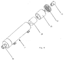
- FIG. 4 Another simpler embodiment of a drive device 1 'according to the invention for blinds or awnings is shown in Fig. 4.
- the trained as an external rotor Transverse flux motor has only a single stator 24 and a single rotor 25, which are similar to the described stator 18, 19 and rotor parts 20, 23 are formed. This drive device is intended for smaller power.
- multi-stage transverse flux motors can also be used according to the principle described with reference to FIG. 1, wherein the rotor parts and stator parts each have the same modular design.
Landscapes
- Engineering & Computer Science (AREA)
- Power Engineering (AREA)
- Structural Engineering (AREA)
- Architecture (AREA)
- Civil Engineering (AREA)
- Blinds (AREA)
- Operating, Guiding And Securing Of Roll- Type Closing Members (AREA)
- Reciprocating, Oscillating Or Vibrating Motors (AREA)
- Hydraulic Motors (AREA)
- Yarns And Mechanical Finishing Of Yarns Or Ropes (AREA)
- Ultra Sonic Daignosis Equipment (AREA)
Abstract
Description
Die Erfindung betrifft eine Antriebsvorrichtung gemäß dem Oberbegriff des Anspruchs 1.The invention relates to a drive device according to the preamble of
Derartige Antriebsvorrichtungen sind allgemein vielfach bekannt. Sie arbeiten mit elektrischem Strom und weisen einen mit einer Spulenanordnung bewickelten Stator und einen mit der Antriebswelle verbundenen Rotor auf. Vielfach weisen auch die Rotoren eine Spulenanordnung auf, und die Rotoren sind mit Schleifringen und Kohlestiften zur Zuführung des Rotorstroms versehen, oder die Motoren sind als Asynchronmotoren ausgebildet. Im Allgemeinen umfasst die Antriebsvorrichtung außer dem eigentlichen Motor noch eine Endabschalteinheit, eine Bremse und ein mehrstufiges Planetengetriebe. Mit diesen Antriebsvorrichtungen können die bei Jalousien, Markisen, Rollläden und dergleichen erforderlichen Drehmomente nur mittels eines hohe Untersetzungen (> ca. 1:100) aufweisenden Getriebes erreicht werden. Bei Einphasen-Kondensator-Motoren ist zudem eine Drehzahlregelung kaum möglich. Die Drehzahl der Antriebsvorrichtungen ist nicht konstant, sondern belastungsabhängig. Ferner ist die Fertigung dieser Antriebsvorrichtungen recht kompliziert und damit kostenträchtig.Such drive devices are generally widely known. They work with electric current and have a stator wound with a coil arrangement and a rotor connected to the drive shaft. In many cases, the rotors have a coil arrangement, and the rotors are provided with slip rings and carbon pencils for supplying the rotor current, or the motors are designed as asynchronous motors. In general, the drive device comprises in addition to the actual engine nor a Endabschalteinheit, a brake and a multi-stage planetary gear. With these drive devices, the torques required for blinds, awnings, shutters and the like can only be achieved by means of a high reduction ratio (> approximately 1: 100) having the transmission. at Single-phase capacitor motors, a speed control is also hardly possible. The speed of the drive devices is not constant, but load-dependent. Furthermore, the production of these drive devices is quite complicated and thus costly.
Durch zahlreiche Dokumente sind so genannte Transversalflussmotoren bekannt. Beispielsweise ist in der DE 101 04 234 A1 ein als Innenläufer ausgebildeter Transversalflussmotor mit einem Stator offenbart, der eine ringförmige Statorspule mit einer Mittelachse aufweist und bei dem die Statorspule längs ihres Umfangs von zumindest annähernd C-förmigen Statorblechpaketen umfasst ist. Jeweils benachbarte C-förmige Statorblechpakete sind dabei abwechselnd mit den freien Enden ihrer Schenkel radial nach innen und nach außen gerichtet. Die Statorbleche sind zumindest abschnittsweise im Wesentlichen tangential zur Mittelachse der Statorspule oder dem Umfang der Statorspule folgend orientiert. Der Motor weist ferner einen Rotor aus einem mit der Antriebswelle verbundenen Träger und mindestens einem am Träger befestigten Ring aus abwechselnden Magnetpolen auf, die den Schenkeln jeweils benachbarter Statorblechpakete gegenüberstehen. Mit einem solchen Transversalflussmotor können sehr kompakte, niedrigdrehende Motoren mit sehr hohem Wirkungsgrad und einer hohen Leistung auf einfache Weise hergestellt werden.Through numerous documents so-called transversal flux motors are known. For example, DE 101 04 234 A1 discloses a transverse flux motor designed as an internal rotor with a stator which has an annular stator coil with a central axis and in which the stator coil is surrounded along its circumference by at least approximately C-shaped stator lamination stacks. In each case adjacent C-shaped stator lamination packages are directed alternately with the free ends of their legs radially inwardly and outwardly. The stator laminations are oriented at least in sections substantially tangentially to the center axis of the stator coil or to the circumference of the stator coil. The motor further comprises a rotor of a carrier connected to the drive shaft and at least one ring attached to the carrier of alternating magnetic poles, which face the legs of each adjacent stator lamination. Such a transverse flux motor can be used to produce very compact, low-speed motors with very high efficiency and high power in a simple manner.
Aus der DE 196 34 949 C1 ist ein Transversalflussmotor bekannt, der mit einem Außenläufer ausgebildet und mit einem Permanentmagnete aufweisenden Rotor versehen ist. Es sind auch mehrphasige Motoren dargestellt, wobei mindestens ein Gehäusetrennteil verwendet wird, an dem zu beiden Seiten Statorteile mit jeweils einer Spulenanordnung befestigt sind. An eine Verwendungsmöglichkeit als Rohrmotor für Jalousien usw. ist aber nicht gedacht worden. Die dargestellten Ausführungsbeispiele eignen sich auch nicht dafür, weil die Außenläufer über einen Ringerheblicher Höhemit der Motorwelle verbunden sind und der Motor daher nicht die für einen Rohrmotor nötige Kompaktheit aufweist.From DE 196 34 949 C1 a transverse flux motor is known, which is formed with an external rotor and provided with a rotor having permanent magnets. There are also shown multi-phase motors, wherein at least one Gehäusetrennteil is used, are attached to the stator on both sides, each with a coil assembly. At a use as a tubular motor for blinds, etc. but was not thought. The illustrated embodiments are also not suitable, because the external rotor are connected via a Ringerheblicher Höhemit the motor shaft and therefore the motor does not have the necessary compactness for a tubular motor.
Aus der DE 199 53 200 A1, der DE 102 37 203 A1 und WO 96/19861 A1 sind Transversalflussmotoren bekannt, die als Innenläufer ausgebildet sind. Bei der erstgenannten Schrift ist ein Getriebe vorgesehen, und es wird auch eine mit einer Schlingfeder arbeitende Motorbremse vorgeschlagen. Bei der zweitgenannten Schrift wird darauf hingewiesen, dass ein mechanisches Getriebe auch entfallen kann und die Drehmomente an an die Raddrehzahlen von Fahrzeugen leicht angepasst werden können.From DE 199 53 200 A1, DE 102 37 203 A1 and WO 96/19861 A1 transverse flux motors are known, which are designed as internal rotor. At the former Scripture is provided a gear, and it is also proposed working with a wrap engine brake. In the second mentioned document, it should be noted that a mechanical transmission can also be omitted and the torques can be easily adapted to the wheel speeds of vehicles.
Ferner ist beispielsweise aus der WO 99/48190 A1 ein Transversalflussmotor mit C-förmigen Magnetflussjochen bekannt, die zusätzlich am Luftspalt I-förmige Magnetflussjoche aufweisen.Furthermore, WO 99/48190 A1 discloses, for example, a transverse flux motor with C-shaped magnetic flux yokes which additionally have I-shaped magnetic flux yokes at the air gap.
Schließlich ist beispielsweise aus der EP 0 218 522 noch ein Transversalflussmotor bekannt, der ebenfalls C-förmige Magnetflussjoche und zusätzlich in axialen Reihen angeordnete Magnetfluss-Leitstücke aufweist. Letztere sind mit Permanentmagnetelementen des Rotors zumindest teilweise fluchtend ausgerichtet. Hierbei verläuft der Luftspalt axial.Finally, for example, EP 0 218 522 discloses a transverse flux motor which likewise has C-shaped magnetic flux yokes and, additionally, magnetic flux conducting pieces arranged in axial rows. The latter are at least partially aligned with permanent magnet elements of the rotor. Here, the air gap is axial.
Die bekannten Transversalflussmotoren werden insbesondere in der Automobilindustrie oder in Werkzeugmaschinen verwendet und sind nicht für einen Einsatz bei Rohrmotoren für Jalousien, Markisen, Rollläden und dergleichen gedacht.The known transverse flux motors are used in particular in the automotive industry or in machine tools and are not intended for use in tubular motors for blinds, awnings, shutters and the like.
Die Erfindung hat zur Aufgabe, eine Antriebsvorrichtung der im Oberbegriff des Anspruchs 1 genannten Art zu schaffen, die für Jalousien, Markisen, Rollläden und dergleichen geeigneter ist. Insbesondere soll ein hohes Drehmoment auf beengtem Raum bereitgestellt werden, und niedrige Drehzahlen, hohe Haltemomente und ein einfacher und robuster Aufbau sollen erreicht werden.The invention has for its object to provide a drive device referred to in the preamble of
Diese Aufgabe wird mit den Merkmalen des Anspruchs 1 gelöst.This object is achieved with the features of
Die Antriebsvorrichtung gemäß der Erfindung kann auf engstem Raum, wie es für den Anwendungszweck gewünscht wird, zusammengebaut werden, wobei sie bei hoher Leistungsdichte hochwirksam arbeitet. Durch die gedrängte Bauweise wird der Wirkungsgrad des Motors erhöht. Die drehmomentabhängigen Verluste können vermindert werden. Gegenüber den sonstigen Motoren liegen dabei die Spulen konzentrisch um die Motorachse, die damit einfach hergestellt werden können.The drive device according to the invention can be assembled in a confined space, as desired for the application, while working highly efficiently at high power density. The compact design increases the efficiency of the engine. The torque-dependent losses can be reduced become. Compared to the other engines, the coils are concentric around the motor axis, which can therefore be easily manufactured.
Da das verwendete Motorprinzip hohe Drehmomente bei kleinen Drehzahlen zur Verfügung stellen kann, kann auf ein Getriebe verzichtet werden. Durch das fehlende Getriebe werden die Geräusche der Antriebsvorrichtung vermindert. Die Drehzahl des Transversalflussmotors kann elektronisch geregelt werden. Durch den hohen Wirkungsgrad ist die Laufzeit viel weniger begrenzt, und diese Antriebsvorrichtung eignet sich auch sehr gut für den Betrieb mit Batterien oder Akkumulatoren.Since the motor principle used can provide high torques at low speeds, a transmission can be dispensed with. The lack of gear noise of the drive device can be reduced. The speed of the transverse flux motor can be controlled electronically. Due to the high efficiency, the runtime is much less limited, and this drive device is also very well suited for operation with batteries or accumulators.
Gemäß einer weiteren Ausbildung der Erfindung kann der Rohrmotor zwei oder mehrere einphasige Motorteile aufweisen, die vorzugsweise im Wesentlichen gleich ausgebildet sind. Dabei kann der für einen einstufigen Motor verwendete Motorteil als Grundmodul bei mehrstufigen Motoren mehrfach eingesetzt werden, so dass Antriebsvorrichtungen höherer Leistung kostengünstig hergestellt werden können.According to a further embodiment of the invention, the tubular motor may comprise two or more single-phase motor parts, which are preferably formed substantially the same. In this case, the motor part used for a single-stage motor can be used multiple times as a basic module in multi-stage motors, so that drive devices higher power can be produced inexpensively.
Eine weitere Ausbildung der Erfindung sieht vor, dass der Transversalflussmotor in einen ersten Motorteil und einen zweiten Motorteil dadurch aufgeteilt ist, dass zwischen den Motorteilen als Teil des Motorgehäuses ein sich radial erstreckender, mit einer Zentralöffnung für die Motorwelle versehener Trennteil, an dem zu beiden Stirnseiten jeweils ein mit einer Spulenanordnung bewickelter Stator befestigt ist, und zu beiden Seiten des Trennteils jeweils ein im Querschnitt C-förmiger, auf der Motorwelle mit seinem Innenrohr befestigter und zum Trennteil sich öffnender Rotorteil vorgesehen ist. Dadurch wird ein einfacher Aufbau des Rohrmotors erzielt.A further embodiment of the invention provides that the transverse flux motor is divided into a first motor part and a second motor part in that between the motor parts as part of the motor housing, a radially extending, provided with a central opening for the motor shaft separator, on both end sides each wound with a coil assembly stator is fixed, and on both sides of the separating part in each case a cross-sectionally C-shaped, provided on the motor shaft with its inner tube and the separating part opening rotor part is provided. As a result, a simple construction of the tubular motor is achieved.
Gemäß einer vorteilhaften, weiteren Ausbildung der Erfindung ist das Innenrohr des Rotorteils teilweise in der Zentralöffnung aufgenommen.According to an advantageous, further embodiment of the invention, the inner tube of the rotor part is partially received in the central opening.
Gemäß einer weiteren Ausbildung der Erfindung gleitet das Innenrohr des Rotorteils in der Zentralöffnung. Die Motorwelle wird dadurch gestützt.According to a further embodiment of the invention, the inner tube of the rotor part slides in the central opening. The motor shaft is supported by it.
Gemäß einer weiteren Ausbildung der Erfindung sind in einem Endteil des Motorgehäuses Steuerelemente für den Motor untergebracht. Diese Steuerelemente dienen vor allem der Endabschaltung und der Motorsteuerung und werden elektronisch betrieben. Die Antriebsvorrichtung kann direkt durch die Netzspannung oder alternativ mit einer Kleinspannung betrieben werden.According to a further embodiment of the invention, controls for the engine are housed in an end portion of the motor housing. These controls are mainly used for the end stop and the engine control and are operated electronically. The drive device can be operated directly by the mains voltage or alternatively with a low voltage.
Gemäß einer weiteren Ausbildung der Erfindung wird der Motor im stromlosen Zustand zum Halten der Last mechanisch verriegelt. Hierbei können insbesondere herkömmliche form-, reib- oder kraftschlüssige Verriegelungen wie die nach dem Schlinfederprinzip, Elektromagnetprinzip oder dergleichen arbeitenden eingesetzt werden.According to a further embodiment of the invention, the motor is mechanically locked in the de-energized state for holding the load. In this case, in particular conventional positive, frictional or non-positive locking devices such as those operating according to the Schlinfeder principle, solenoid principle or the like can be used.
Die Erfindung wird nun anhand von Ausführungsbeispielen näher erläutert. Es zeigen:
- Fig. 1
- eine Seitenansicht einer mit einem Transversalflussmotor arbeitenden, rohrförmigen Antriebsvorrichtung gemäß der Erfindung für Jalousien, Markisen, Rolläden oder dergleichen,
- Fig. 2
- eine Stirnansicht der Antriebsvorrichtung der Fig. 1,
- Fig. 3
- einen vergrößerten Längsschnitt durch die Antriebsvorrichtung der Fig. 1 und
- Fig. 4
- eine perspektivische Explosionsansicht einer weiteren Ausführung einer Antriebsvorrichtung gemäß der Erfindung.
- Fig. 1
- a side view of working with a transverse flux motor tubular drive device according to the invention for blinds, awnings, blinds or the like,
- Fig. 2
- an end view of the drive device of FIG. 1,
- Fig. 3
- an enlarged longitudinal section through the drive device of Fig. 1 and
- Fig. 4
- an exploded perspective view of another embodiment of a drive device according to the invention.
In den Figuren 1 bis 3 ist eine elektrische Antriebsvorrichtung 1 gezeigt, wie sie als Rohrmotor in Wickelrohren von Jalousien, Markisen, Rollläden uns dergleichen zum Einsatz kommt. Die Antriebsvorrichtung ist mit einem rohrförmigen Gehäuse 2 ausgestattet, das einen ersten Motorteil 3, einen zweiten Motorteil 4 und einen Steuerteil 5 aufweist. Die beiden Motorteile 3 und 4 bilden einen zweistufigen Transversalflussmotor, während im Steuerteil 5 die zur Endabschaltung und zur Steuerung des Transversalflussmotors erforderlichen elektronischen Steuerelemente untergebracht sind, die nicht im Einzelnen beschrieben werden. Das Gehäuse 2 ist sind, die nicht im Einzelnen beschrieben werden. Das Gehäuse 2 ist mit vier Schraubfüßen, wie den Schraubfüßen 6-8, versehen. Im Gehäuse 2 ist eine Motorwelle 9 an beiden Endbereichen mittels Kugellagern gelagert. Die Enden der Motorwelle 9 sind jeweils mit einem Kupplungsstück 10 bzw. 11 abgeschlossen. Zum Motorgehäuse 2 gehören ein Gehäusedeckel 12, ein mittlerer erster Trennteil 13 und ein zweiter Trennteil 14, die sich alle drei radial erstrecken und jeweils mit einer Zentralöffnung 15 bzw. 16 bzw. 17 versehen sind. Durch die Zentralöffnungen 15-17 verläuft die Motorwelle 9. Durch den Gehäusedeckel 12 und die Trennteile 13, 14 wird der Transversalflussmotor in die zwei Motorteile 3 und 4 aufgeteilt.In Figures 1 to 3, an
Am mittleren ersten Trennteil 13 sind zu beiden Stirnseiten in nicht dargestellter Weise zwei mit jeweils einer Spulenanordnung versehene Statorteile 18, 19 in Form von Zylindern befestigt. Diese Statorteile tragen über ihren Umfang verteilte, nicht dargestellte Flussleitstücke in nebeneinander liegenden Reihen über die Länge der Statorteile. Zwischen dem Gehäusedeckel 12 und dem Trennteil 13 ist ein im Querschnitt U-förmiger erster Rotorteil 20 mit einem Innenrohr 21 und einem Außenrohr 22 angeordnet. Das Innenrohr 21 ist auf der Motorwelle 9 befestigt, wobei es teilweise in die Zentralöffnungen 15, 16 hineinragt und dort vorzugsweise Gleitlagerfunktionen ausüben kann. Die Innenseite des Außenrohrs 22 ist mit über ihren Umfang verteilten Permanentmagnetelementen in Reihen versehen, die über die Länge dieser Innenseite nebeneinander liegen. In den Reihen sind die Permanentmagnetelemente mit abwechselnder Polarität angeordnet. Diese Permanentmagnetelemente liegen den Flussleitstücken des Stators 18 unter Bildung eines Luftspalts für den Transversalfluss gegenüber. In gleicher Weise ist ein zweiter Rotorteil 23 zwischen dem Trennteil 13 und dem Trennteil 14 angeordnet. Beide Rotorteile 20, 23 öffnen zum Trennteil 13. Der Statorteil 18 ragt dabei in den Rotorteil 20 hinein, während der Statorteil 19 in den Rotorteil 23 hineinragt. Durch den Transversalmagnetfluss wird eine Kraft erzeugt, die die Rotorteile 20, 23 und damit die Motorwelle 9 zum Drehen bringen.At the middle first separating
Eine weitere einfachere Ausführung einer Antriebsvorrichtung 1' gemäß der Erfindung für Jalousien oder Markisen ist in Fig. 4 dargestellt. Der als Außenläufer ausgebildete Transversalflussmotor weist nur einen einzigen Stator 24 und einen einzigen Rotor 25 auf, die ähnlich wie die beschriebenen Statorteile 18, 19 bzw. Rotorteile 20, 23 ausgebildet sind. Diese Antriebsvorrichtung ist für kleinere Leistungen vorgesehen.Another simpler embodiment of a drive device 1 'according to the invention for blinds or awnings is shown in Fig. 4. The trained as an external rotor Transverse flux motor has only a
Wenn größere Leistungen erforderlich sind, können auch mehrstufige Transversalflussmotoren nach dem anhand der Fig. 1 beschriebenen Prinzip verwendet werden, wobei die Rotorteile und Statorteile jeweils die gleiche Modulbauart aufweisen.If larger powers are required, multi-stage transverse flux motors can also be used according to the principle described with reference to FIG. 1, wherein the rotor parts and stator parts each have the same modular design.
Claims (7)
dadurch gekennzeichnet,
dass als Rohrmotor (3, 4) ein Transversalflussmotor verwendet wird, der als Außenläufer ausgebildet und mit einem Permanentmagnetelement aufweisenden Rotor (20, 23, 25) versehen ist.Drive device (1, 1 ') with an electrically operated, a stator (18, 19; 24) and a rotor (20, 23; 25) comprising tubular motor for blinds, awnings, shutters and the like,
characterized,
in that a transverse flux motor which is designed as an external rotor and is provided with a rotor (20, 23, 25) having a permanent magnet element is used as the tubular motor (3, 4).
dadurch gekennzeichnet,
dass der Rohrmotor zwei oder mehrere einphasige Motorteile (3, 4) aufweist, die vorzugsweise im Wesentlichen gleich ausgebildet sind.Drive device according to claim 1,
characterized,
in that the tubular motor has two or more single-phase motor parts (3, 4), which are preferably of essentially the same design.
dadurch gekennzeichnet,
dass der Transversalflussmotor in einen ersten Motorteil (3) und einen zweiten Motorteil (4) dadurch aufgeteilt ist, dass zwischen den Motorteilen als Teil des Motorgehäuses (2) ein sich radial erstreckender, mit einer Zentralöffnung (16) für die Motorwelle (9) versehener Trennteil (13), an dem zu beiden Stirnseiten jeweils ein mit einer Spulenanordnung bewickelter Statorteil (18, 19) befestigt ist, und zu beiden Seiten des Trennteils jeweils ein im Querschnitt U-förmiger, auf der Motorwelle mit seinem Innenrohr (21) befestigter und zum Trennteil (13) sich öffnender Rotorteil (20, 23) vorgesehen ist.Drive device according to claim 1 or 2,
characterized,
in that the transverse flux motor is divided into a first motor part (3) and a second motor part (4) in that a radially extending, with a central opening (16) for the motor shaft (9) is provided between the motor parts as part of the motor housing (2) Separator (13) to which at both end faces in each case a wound with a coil assembly stator (18, 19) is fixed, and on both sides of the separating part in each case a U-shaped, on the motor shaft with its inner tube (21) attached and to the separating part (13) is provided opening rotor part (20, 23).
dadurch gekennzeichnet,
dass das Innenrohr (21) des Rotorteils (20) teilweise in der Zentralöffnung (16) aufgenommen ist.Drive device according to claim 3,
characterized,
that the inner tube (21) of the rotor part (20) is partially received in the central opening (16).
dadurch gekennzeichnet,
dass das Innenrohr (21) des Rotorteils (20) in der Zentralöffnung (16) gelagert ist.Drive device according to claim 4,
characterized,
that the inner pipe (21) is mounted to the rotor part (20) in the central opening (16).
dadurch gekennzeichnet,
dass in einem Endteil (5) oder dem Trennteil des Motorgehäuses (2) elektronische Steuerelemente für den Motor untergebracht sind.Drive device according to one of claims 2 to 5,
characterized,
that in an end part (5) or the separating part of the motor housing (2) electronic controls for the engine are housed.
dadurch gekennzeichnet,
dass der Motor im stromlosen Zustand zum Halten der Last mechanisch, insbesondere durch nach dem Schlingfederprinzip arbeitende Mittel, verriegelt wird.Drive device according to one of claims 1 to 6,
characterized,
that the motor is locked in the de-energized state for holding the load mechanically, in particular by acting on the wrap spring principle means.
Applications Claiming Priority (1)
| Application Number | Priority Date | Filing Date | Title |
|---|---|---|---|
| DE102004063067A DE102004063067A1 (en) | 2004-12-22 | 2004-12-22 | driving device |
Publications (2)
| Publication Number | Publication Date |
|---|---|
| EP1675251A1 true EP1675251A1 (en) | 2006-06-28 |
| EP1675251B1 EP1675251B1 (en) | 2008-02-27 |
Family
ID=35999555
Family Applications (1)
| Application Number | Title | Priority Date | Filing Date |
|---|---|---|---|
| EP05026432A Not-in-force EP1675251B1 (en) | 2004-12-22 | 2005-12-03 | Tube motor for window blinds |
Country Status (4)
| Country | Link |
|---|---|
| EP (1) | EP1675251B1 (en) |
| AT (1) | ATE387745T1 (en) |
| DE (2) | DE102004063067A1 (en) |
| ES (1) | ES2302118T3 (en) |
Cited By (6)
| Publication number | Priority date | Publication date | Assignee | Title |
|---|---|---|---|---|
| WO2009039714A1 (en) * | 2007-09-27 | 2009-04-02 | Jing Chen | A new type tubular motor |
| WO2010011751A1 (en) | 2008-07-22 | 2010-01-28 | Hunter Douglas Inc. | Motor arrangement for window coverings |
| EP2466730A1 (en) * | 2010-12-20 | 2012-06-20 | Cyoris Ag | Gearless roller drive |
| FR2972872A1 (en) * | 2011-03-17 | 2012-09-21 | Somfy Sas | Electric motor i.e. low power electronically commutated brushless synchronous motor, for driving e.g. door, of closing/solar protection facility in building, has stator bars whose parts form outer portion extending parallel to rotation axis |
| US9564792B2 (en) | 2011-03-17 | 2017-02-07 | Somfy Sas | Electric motor and closing or sun protection installation comprising such a motor |
| EP3567208A1 (en) * | 2018-05-11 | 2019-11-13 | Q Torq Ltd. | Modular drive system for a window blind |
Families Citing this family (1)
| Publication number | Priority date | Publication date | Assignee | Title |
|---|---|---|---|---|
| DE102006038576B4 (en) * | 2006-08-20 | 2008-07-03 | Tirron-Elektronik Gmbh | High-poled, permanent magnet synchronous motor with transversal flux guidance, high torque and low rotational inertia |
Citations (3)
| Publication number | Priority date | Publication date | Assignee | Title |
|---|---|---|---|---|
| DE19634949C1 (en) * | 1996-08-29 | 1998-03-05 | Weh Herbert Prof Dr Ing H C | Transversal-flux electrical machine with several transverse magnetic circuits |
| DE10104234A1 (en) * | 2001-01-31 | 2002-08-14 | Compact Dynamics Gmbh | Transversal flux machine, stator for a transverse flux machine |
| US6700246B1 (en) * | 1999-11-05 | 2004-03-02 | Valeo Auto-Electric Wischer Und Motoren Gmbh | Tubutor motor |
Family Cites Families (2)
| Publication number | Priority date | Publication date | Assignee | Title |
|---|---|---|---|---|
| JPH10513035A (en) * | 1994-12-21 | 1998-12-08 | ヒル,ヴォルフガング | Transverse flux machine |
| DE10237203A1 (en) * | 2002-08-14 | 2004-02-26 | Deere & Company, Moline | transverse flux |
-
2004
- 2004-12-22 DE DE102004063067A patent/DE102004063067A1/en not_active Withdrawn
-
2005
- 2005-12-03 EP EP05026432A patent/EP1675251B1/en not_active Not-in-force
- 2005-12-03 ES ES05026432T patent/ES2302118T3/en active Active
- 2005-12-03 DE DE502005002977T patent/DE502005002977D1/en active Active
- 2005-12-03 AT AT05026432T patent/ATE387745T1/en not_active IP Right Cessation
Patent Citations (3)
| Publication number | Priority date | Publication date | Assignee | Title |
|---|---|---|---|---|
| DE19634949C1 (en) * | 1996-08-29 | 1998-03-05 | Weh Herbert Prof Dr Ing H C | Transversal-flux electrical machine with several transverse magnetic circuits |
| US6700246B1 (en) * | 1999-11-05 | 2004-03-02 | Valeo Auto-Electric Wischer Und Motoren Gmbh | Tubutor motor |
| DE10104234A1 (en) * | 2001-01-31 | 2002-08-14 | Compact Dynamics Gmbh | Transversal flux machine, stator for a transverse flux machine |
Cited By (10)
| Publication number | Priority date | Publication date | Assignee | Title |
|---|---|---|---|---|
| WO2009039714A1 (en) * | 2007-09-27 | 2009-04-02 | Jing Chen | A new type tubular motor |
| WO2010011751A1 (en) | 2008-07-22 | 2010-01-28 | Hunter Douglas Inc. | Motor arrangement for window coverings |
| EP2315541A1 (en) * | 2008-07-22 | 2011-05-04 | Hunter Douglas Inc. | Motor arrangement for window coverings |
| EP2315541A4 (en) * | 2008-07-22 | 2014-07-30 | Hunter Douglas | Motor arrangement for window coverings |
| EP2466730A1 (en) * | 2010-12-20 | 2012-06-20 | Cyoris Ag | Gearless roller drive |
| WO2012084861A3 (en) * | 2010-12-20 | 2013-06-13 | Cyoris Ag | Transmissionless roller drive |
| FR2972872A1 (en) * | 2011-03-17 | 2012-09-21 | Somfy Sas | Electric motor i.e. low power electronically commutated brushless synchronous motor, for driving e.g. door, of closing/solar protection facility in building, has stator bars whose parts form outer portion extending parallel to rotation axis |
| US9564792B2 (en) | 2011-03-17 | 2017-02-07 | Somfy Sas | Electric motor and closing or sun protection installation comprising such a motor |
| EP3567208A1 (en) * | 2018-05-11 | 2019-11-13 | Q Torq Ltd. | Modular drive system for a window blind |
| WO2019215322A1 (en) * | 2018-05-11 | 2019-11-14 | Q Torq Ltd. | Modular drive system for a window blind |
Also Published As
| Publication number | Publication date |
|---|---|
| ATE387745T1 (en) | 2008-03-15 |
| DE102004063067A1 (en) | 2006-07-13 |
| DE502005002977D1 (en) | 2008-04-10 |
| ES2302118T3 (en) | 2008-07-01 |
| EP1675251B1 (en) | 2008-02-27 |
Similar Documents
| Publication | Publication Date | Title |
|---|---|---|
| EP1675251B1 (en) | Tube motor for window blinds | |
| EP0799519B1 (en) | Transverse flux machine | |
| DE602004012340T2 (en) | Turbocharger with electric auxiliary drive | |
| EP1959546B1 (en) | Stator construction component | |
| EP0394527B1 (en) | Heteropolary excited synchronous machine | |
| DE69703566T2 (en) | Switched reluctance motor | |
| EP0954087A1 (en) | Dynamoelectrical transmission and centrifugal pump with such transmission | |
| DE102005015657A1 (en) | Electric machine and method for field and armature position of a permanent-magnet electric machine | |
| DE102005047771A1 (en) | Rotor arrangement for electrical machine has stacked plates with some openings bridged at outer ends by outer bridges and other openings open at outer end | |
| EP3479462B1 (en) | Electrical machine system | |
| EP0910154B1 (en) | Reluctance motor | |
| EP1927178A1 (en) | Electrical drive machine | |
| DE4300440C2 (en) | Electric transverse flux machine with annular winding strands | |
| EP0422539A1 (en) | Electrical machine with a rotor and a stator | |
| DE102020114856B3 (en) | Electric radial flux machine and drive train | |
| DE19704769C2 (en) | Multi-strand synchronous machine with permanent magnets and coil modules | |
| EP2073358A2 (en) | Compact actuator | |
| EP2652862B1 (en) | Machine component for an electrical machine | |
| DE4138014C1 (en) | Electromechanical power converter in rotary or linear form - has permanent magnets assembled in rotor driven by AC stator winding with pole elements | |
| EP2656484B1 (en) | Transverse flux machine | |
| DE10138211A1 (en) | Magnetic centering torque motor | |
| DE10021368B4 (en) | Mechatronic actuator | |
| WO2023208774A1 (en) | Two-phase motor, in particular for driving a conveyor belt | |
| DE202020103021U1 (en) | Magnetic gear device | |
| WO2017148601A1 (en) | Asynchronous machine |
Legal Events
| Date | Code | Title | Description |
|---|---|---|---|
| PUAI | Public reference made under article 153(3) epc to a published international application that has entered the european phase |
Free format text: ORIGINAL CODE: 0009012 |
|
| AK | Designated contracting states |
Kind code of ref document: A1 Designated state(s): AT BE BG CH CY CZ DE DK EE ES FI FR GB GR HU IE IS IT LI LT LU LV MC NL PL PT RO SE SI SK TR |
|
| AX | Request for extension of the european patent |
Extension state: AL BA HR MK YU |
|
| 17P | Request for examination filed |
Effective date: 20061228 |
|
| 17Q | First examination report despatched |
Effective date: 20070205 |
|
| AKX | Designation fees paid |
Designated state(s): AT BE BG CH CY CZ DE DK EE ES FI FR GB GR HU IE IS IT LI LT LU LV MC NL PL PT RO SE SI SK TR |
|
| GRAP | Despatch of communication of intention to grant a patent |
Free format text: ORIGINAL CODE: EPIDOSNIGR1 |
|
| GRAS | Grant fee paid |
Free format text: ORIGINAL CODE: EPIDOSNIGR3 |
|
| GRAA | (expected) grant |
Free format text: ORIGINAL CODE: 0009210 |
|
| AK | Designated contracting states |
Kind code of ref document: B1 Designated state(s): AT BE BG CH CY CZ DE DK EE ES FI FR GB GR HU IE IS IT LI LT LU LV MC NL PL PT RO SE SI SK TR |
|
| REG | Reference to a national code |
Ref country code: GB Ref legal event code: FG4D Free format text: NOT ENGLISH |
|
| REG | Reference to a national code |
Ref country code: CH Ref legal event code: EP |
|
| REG | Reference to a national code |
Ref country code: IE Ref legal event code: FG4D Free format text: LANGUAGE OF EP DOCUMENT: GERMAN |
|
| REF | Corresponds to: |
Ref document number: 502005002977 Country of ref document: DE Date of ref document: 20080410 Kind code of ref document: P |
|
| REG | Reference to a national code |
Ref country code: ES Ref legal event code: FG2A Ref document number: 2302118 Country of ref document: ES Kind code of ref document: T3 |
|
| PG25 | Lapsed in a contracting state [announced via postgrant information from national office to epo] |
Ref country code: FI Free format text: LAPSE BECAUSE OF FAILURE TO SUBMIT A TRANSLATION OF THE DESCRIPTION OR TO PAY THE FEE WITHIN THE PRESCRIBED TIME-LIMIT Effective date: 20080227 Ref country code: IS Free format text: LAPSE BECAUSE OF FAILURE TO SUBMIT A TRANSLATION OF THE DESCRIPTION OR TO PAY THE FEE WITHIN THE PRESCRIBED TIME-LIMIT Effective date: 20080627 |
|
| NLV1 | Nl: lapsed or annulled due to failure to fulfill the requirements of art. 29p and 29m of the patents act | ||
| PG25 | Lapsed in a contracting state [announced via postgrant information from national office to epo] |
Ref country code: SI Free format text: LAPSE BECAUSE OF FAILURE TO SUBMIT A TRANSLATION OF THE DESCRIPTION OR TO PAY THE FEE WITHIN THE PRESCRIBED TIME-LIMIT Effective date: 20080227 Ref country code: LV Free format text: LAPSE BECAUSE OF FAILURE TO SUBMIT A TRANSLATION OF THE DESCRIPTION OR TO PAY THE FEE WITHIN THE PRESCRIBED TIME-LIMIT Effective date: 20080227 Ref country code: PL Free format text: LAPSE BECAUSE OF FAILURE TO SUBMIT A TRANSLATION OF THE DESCRIPTION OR TO PAY THE FEE WITHIN THE PRESCRIBED TIME-LIMIT Effective date: 20080227 |
|
| REG | Reference to a national code |
Ref country code: IE Ref legal event code: FD4D |
|
| ET | Fr: translation filed | ||
| PG25 | Lapsed in a contracting state [announced via postgrant information from national office to epo] |
Ref country code: NL Free format text: LAPSE BECAUSE OF FAILURE TO SUBMIT A TRANSLATION OF THE DESCRIPTION OR TO PAY THE FEE WITHIN THE PRESCRIBED TIME-LIMIT Effective date: 20080227 Ref country code: PT Free format text: LAPSE BECAUSE OF FAILURE TO SUBMIT A TRANSLATION OF THE DESCRIPTION OR TO PAY THE FEE WITHIN THE PRESCRIBED TIME-LIMIT Effective date: 20080721 Ref country code: CZ Free format text: LAPSE BECAUSE OF FAILURE TO SUBMIT A TRANSLATION OF THE DESCRIPTION OR TO PAY THE FEE WITHIN THE PRESCRIBED TIME-LIMIT Effective date: 20080227 Ref country code: SE Free format text: LAPSE BECAUSE OF FAILURE TO SUBMIT A TRANSLATION OF THE DESCRIPTION OR TO PAY THE FEE WITHIN THE PRESCRIBED TIME-LIMIT Effective date: 20080527 Ref country code: SK Free format text: LAPSE BECAUSE OF FAILURE TO SUBMIT A TRANSLATION OF THE DESCRIPTION OR TO PAY THE FEE WITHIN THE PRESCRIBED TIME-LIMIT Effective date: 20080227 Ref country code: DK Free format text: LAPSE BECAUSE OF FAILURE TO SUBMIT A TRANSLATION OF THE DESCRIPTION OR TO PAY THE FEE WITHIN THE PRESCRIBED TIME-LIMIT Effective date: 20080227 Ref country code: IE Free format text: LAPSE BECAUSE OF FAILURE TO SUBMIT A TRANSLATION OF THE DESCRIPTION OR TO PAY THE FEE WITHIN THE PRESCRIBED TIME-LIMIT Effective date: 20080227 |
|
| PG25 | Lapsed in a contracting state [announced via postgrant information from national office to epo] |
Ref country code: RO Free format text: LAPSE BECAUSE OF FAILURE TO SUBMIT A TRANSLATION OF THE DESCRIPTION OR TO PAY THE FEE WITHIN THE PRESCRIBED TIME-LIMIT Effective date: 20080227 |
|
| PLBE | No opposition filed within time limit |
Free format text: ORIGINAL CODE: 0009261 |
|
| STAA | Information on the status of an ep patent application or granted ep patent |
Free format text: STATUS: NO OPPOSITION FILED WITHIN TIME LIMIT |
|
| PG25 | Lapsed in a contracting state [announced via postgrant information from national office to epo] |
Ref country code: LT Free format text: LAPSE BECAUSE OF FAILURE TO SUBMIT A TRANSLATION OF THE DESCRIPTION OR TO PAY THE FEE WITHIN THE PRESCRIBED TIME-LIMIT Effective date: 20080227 |
|
| 26N | No opposition filed |
Effective date: 20081128 |
|
| PG25 | Lapsed in a contracting state [announced via postgrant information from national office to epo] |
Ref country code: BG Free format text: LAPSE BECAUSE OF FAILURE TO SUBMIT A TRANSLATION OF THE DESCRIPTION OR TO PAY THE FEE WITHIN THE PRESCRIBED TIME-LIMIT Effective date: 20080527 Ref country code: EE Free format text: LAPSE BECAUSE OF FAILURE TO SUBMIT A TRANSLATION OF THE DESCRIPTION OR TO PAY THE FEE WITHIN THE PRESCRIBED TIME-LIMIT Effective date: 20080227 |
|
| BERE | Be: lapsed |
Owner name: GERHARD GEIGER G.M.B.H. & CO. Effective date: 20081231 |
|
| PG25 | Lapsed in a contracting state [announced via postgrant information from national office to epo] |
Ref country code: MC Free format text: LAPSE BECAUSE OF NON-PAYMENT OF DUE FEES Effective date: 20081231 Ref country code: CY Free format text: LAPSE BECAUSE OF FAILURE TO SUBMIT A TRANSLATION OF THE DESCRIPTION OR TO PAY THE FEE WITHIN THE PRESCRIBED TIME-LIMIT Effective date: 20080227 |
|
| PG25 | Lapsed in a contracting state [announced via postgrant information from national office to epo] |
Ref country code: BE Free format text: LAPSE BECAUSE OF NON-PAYMENT OF DUE FEES Effective date: 20081231 |
|
| PGFP | Annual fee paid to national office [announced via postgrant information from national office to epo] |
Ref country code: ES Payment date: 20091222 Year of fee payment: 5 |
|
| PGFP | Annual fee paid to national office [announced via postgrant information from national office to epo] |
Ref country code: FR Payment date: 20100108 Year of fee payment: 5 Ref country code: IT Payment date: 20091221 Year of fee payment: 5 |
|
| PG25 | Lapsed in a contracting state [announced via postgrant information from national office to epo] |
Ref country code: AT Free format text: LAPSE BECAUSE OF NON-PAYMENT OF DUE FEES Effective date: 20081203 |
|
| PGFP | Annual fee paid to national office [announced via postgrant information from national office to epo] |
Ref country code: DE Payment date: 20091222 Year of fee payment: 5 |
|
| PG25 | Lapsed in a contracting state [announced via postgrant information from national office to epo] |
Ref country code: LU Free format text: LAPSE BECAUSE OF NON-PAYMENT OF DUE FEES Effective date: 20081203 Ref country code: HU Free format text: LAPSE BECAUSE OF FAILURE TO SUBMIT A TRANSLATION OF THE DESCRIPTION OR TO PAY THE FEE WITHIN THE PRESCRIBED TIME-LIMIT Effective date: 20080828 |
|
| REG | Reference to a national code |
Ref country code: CH Ref legal event code: PL |
|
| GBPC | Gb: european patent ceased through non-payment of renewal fee |
Effective date: 20091203 |
|
| PG25 | Lapsed in a contracting state [announced via postgrant information from national office to epo] |
Ref country code: TR Free format text: LAPSE BECAUSE OF FAILURE TO SUBMIT A TRANSLATION OF THE DESCRIPTION OR TO PAY THE FEE WITHIN THE PRESCRIBED TIME-LIMIT Effective date: 20080227 |
|
| PG25 | Lapsed in a contracting state [announced via postgrant information from national office to epo] |
Ref country code: GR Free format text: LAPSE BECAUSE OF FAILURE TO SUBMIT A TRANSLATION OF THE DESCRIPTION OR TO PAY THE FEE WITHIN THE PRESCRIBED TIME-LIMIT Effective date: 20080528 Ref country code: CH Free format text: LAPSE BECAUSE OF NON-PAYMENT OF DUE FEES Effective date: 20091231 Ref country code: LI Free format text: LAPSE BECAUSE OF NON-PAYMENT OF DUE FEES Effective date: 20091231 |
|
| PG25 | Lapsed in a contracting state [announced via postgrant information from national office to epo] |
Ref country code: GB Free format text: LAPSE BECAUSE OF NON-PAYMENT OF DUE FEES Effective date: 20091203 |
|
| REG | Reference to a national code |
Ref country code: FR Ref legal event code: ST Effective date: 20110831 |
|
| PG25 | Lapsed in a contracting state [announced via postgrant information from national office to epo] |
Ref country code: FR Free format text: LAPSE BECAUSE OF NON-PAYMENT OF DUE FEES Effective date: 20110103 |
|
| REG | Reference to a national code |
Ref country code: DE Ref legal event code: R119 Ref document number: 502005002977 Country of ref document: DE Effective date: 20110701 |
|
| PG25 | Lapsed in a contracting state [announced via postgrant information from national office to epo] |
Ref country code: DE Free format text: LAPSE BECAUSE OF NON-PAYMENT OF DUE FEES Effective date: 20110701 |
|
| PG25 | Lapsed in a contracting state [announced via postgrant information from national office to epo] |
Ref country code: IT Free format text: LAPSE BECAUSE OF NON-PAYMENT OF DUE FEES Effective date: 20101203 |
|
| REG | Reference to a national code |
Ref country code: ES Ref legal event code: FD2A Effective date: 20120206 |
|
| PG25 | Lapsed in a contracting state [announced via postgrant information from national office to epo] |
Ref country code: ES Free format text: LAPSE BECAUSE OF NON-PAYMENT OF DUE FEES Effective date: 20101204 |