EP1675111B1 - Optical pickup actuator and optical recording/reproducing apparatus - Google Patents
Optical pickup actuator and optical recording/reproducing apparatus Download PDFInfo
- Publication number
- EP1675111B1 EP1675111B1 EP05257570A EP05257570A EP1675111B1 EP 1675111 B1 EP1675111 B1 EP 1675111B1 EP 05257570 A EP05257570 A EP 05257570A EP 05257570 A EP05257570 A EP 05257570A EP 1675111 B1 EP1675111 B1 EP 1675111B1
- Authority
- EP
- European Patent Office
- Prior art keywords
- optical pickup
- bobbin
- focusing
- pickup actuator
- coils
- Prior art date
- Legal status (The legal status is an assumption and is not a legal conclusion. Google has not performed a legal analysis and makes no representation as to the accuracy of the status listed.)
- Expired - Fee Related
Links
Images

Classifications
-
- G—PHYSICS
- G11—INFORMATION STORAGE
- G11B—INFORMATION STORAGE BASED ON RELATIVE MOVEMENT BETWEEN RECORD CARRIER AND TRANSDUCER
- G11B7/00—Recording or reproducing by optical means, e.g. recording using a thermal beam of optical radiation by modifying optical properties or the physical structure, reproducing using an optical beam at lower power by sensing optical properties; Record carriers therefor
- G11B7/08—Disposition or mounting of heads or light sources relatively to record carriers
-
- G—PHYSICS
- G11—INFORMATION STORAGE
- G11B—INFORMATION STORAGE BASED ON RELATIVE MOVEMENT BETWEEN RECORD CARRIER AND TRANSDUCER
- G11B7/00—Recording or reproducing by optical means, e.g. recording using a thermal beam of optical radiation by modifying optical properties or the physical structure, reproducing using an optical beam at lower power by sensing optical properties; Record carriers therefor
- G11B7/12—Heads, e.g. forming of the optical beam spot or modulation of the optical beam
- G11B7/135—Means for guiding the beam from the source to the record carrier or from the record carrier to the detector
- G11B7/1372—Lenses
- G11B7/1374—Objective lenses
-
- G—PHYSICS
- G11—INFORMATION STORAGE
- G11B—INFORMATION STORAGE BASED ON RELATIVE MOVEMENT BETWEEN RECORD CARRIER AND TRANSDUCER
- G11B7/00—Recording or reproducing by optical means, e.g. recording using a thermal beam of optical radiation by modifying optical properties or the physical structure, reproducing using an optical beam at lower power by sensing optical properties; Record carriers therefor
- G11B7/08—Disposition or mounting of heads or light sources relatively to record carriers
- G11B7/09—Disposition or mounting of heads or light sources relatively to record carriers with provision for moving the light beam or focus plane for the purpose of maintaining alignment of the light beam relative to the record carrier during transducing operation, e.g. to compensate for surface irregularities of the latter or for track following
- G11B7/0925—Electromechanical actuators for lens positioning
- G11B7/0933—Details of stationary parts
-
- G—PHYSICS
- G11—INFORMATION STORAGE
- G11B—INFORMATION STORAGE BASED ON RELATIVE MOVEMENT BETWEEN RECORD CARRIER AND TRANSDUCER
- G11B7/00—Recording or reproducing by optical means, e.g. recording using a thermal beam of optical radiation by modifying optical properties or the physical structure, reproducing using an optical beam at lower power by sensing optical properties; Record carriers therefor
- G11B7/08—Disposition or mounting of heads or light sources relatively to record carriers
- G11B7/09—Disposition or mounting of heads or light sources relatively to record carriers with provision for moving the light beam or focus plane for the purpose of maintaining alignment of the light beam relative to the record carrier during transducing operation, e.g. to compensate for surface irregularities of the latter or for track following
- G11B7/0925—Electromechanical actuators for lens positioning
- G11B7/0935—Details of the moving parts
-
- G—PHYSICS
- G11—INFORMATION STORAGE
- G11B—INFORMATION STORAGE BASED ON RELATIVE MOVEMENT BETWEEN RECORD CARRIER AND TRANSDUCER
- G11B7/00—Recording or reproducing by optical means, e.g. recording using a thermal beam of optical radiation by modifying optical properties or the physical structure, reproducing using an optical beam at lower power by sensing optical properties; Record carriers therefor
- G11B7/08—Disposition or mounting of heads or light sources relatively to record carriers
- G11B7/09—Disposition or mounting of heads or light sources relatively to record carriers with provision for moving the light beam or focus plane for the purpose of maintaining alignment of the light beam relative to the record carrier during transducing operation, e.g. to compensate for surface irregularities of the latter or for track following
- G11B7/095—Disposition or mounting of heads or light sources relatively to record carriers with provision for moving the light beam or focus plane for the purpose of maintaining alignment of the light beam relative to the record carrier during transducing operation, e.g. to compensate for surface irregularities of the latter or for track following specially adapted for discs, e.g. for compensation of eccentricity or wobble
- G11B7/0956—Disposition or mounting of heads or light sources relatively to record carriers with provision for moving the light beam or focus plane for the purpose of maintaining alignment of the light beam relative to the record carrier during transducing operation, e.g. to compensate for surface irregularities of the latter or for track following specially adapted for discs, e.g. for compensation of eccentricity or wobble to compensate for tilt, skew, warp or inclination of the disc, i.e. maintain the optical axis at right angles to the disc
-
- G—PHYSICS
- G11—INFORMATION STORAGE
- G11B—INFORMATION STORAGE BASED ON RELATIVE MOVEMENT BETWEEN RECORD CARRIER AND TRANSDUCER
- G11B7/00—Recording or reproducing by optical means, e.g. recording using a thermal beam of optical radiation by modifying optical properties or the physical structure, reproducing using an optical beam at lower power by sensing optical properties; Record carriers therefor
- G11B2007/0003—Recording, reproducing or erasing systems characterised by the structure or type of the carrier
- G11B2007/0006—Recording, reproducing or erasing systems characterised by the structure or type of the carrier adapted for scanning different types of carrier, e.g. CD & DVD
Definitions
- the present invention relates to an optical pickup actuator and an optical recording/reproducing apparatus.
- the present invention relates to an optical pickup actuator for driving an objective lens mounted on the actuator in such a way that information can be recorded into, and reproduced from, an optical information storage medium, and an optical recording/reproducing apparatus having the same.
- a Digital Versatile Disk (DVD) is recorded/reproduced using an objective lens having a numerical aperture of 0.6 (in a recordable type, 0.65) and a light having a wavelength of 650 nm (or 635 nm). If such a DVD has a diameter of 120 mm and a track pitch of 0.75 ⁇ m, the DVD has a recording capacity of not less than 4.7 GB on one side thereof.
- Such a DVD is not sufficient as a recording medium for recording moving image information of an HD (High Definition) grade, because a recording capacity of, for example, not less than 23 GB on one side of a DVD is required to record 135 minutes of moving image information in the HD grade.
- HD High Definition
- HD-DVD High Definition-DVD
- red color that is, a blue light
- objective lens having a numerical aperture larger than 0.6
- the thickness of the optical disc may be reduced as the numerical aperture of an objective lens is increased for obtaining a high density.
- the thickness has been reduced from 1.2 mm for Compact Discs (CD's) to 0.6 mm for DVD's.
- CD's Compact Discs
- HD-DVD's it is highly feasible for the thickness to be 0.1 mm.
- the numerical aperture of an objective lens has been increased from 0.45 (for CD's) to 0.6 (for DVD's).
- the numerical aperture it is highly feasible for the numerical aperture to be 0.85.
- a celadon light source to be employed as a light source for HD-DVD's in consideration of a record capacity.
- a compatible type optical pickup capable of high-density recording/reproduction to separately include at least one objective lens for use in recording/reproducing a CD and/or a DVD and an objective lens for use in high-density recording, wherein the objective lens for use in high-density recording has a higher numerical aperture than the objective lens for use in recording a CD and/or a DVD, so as to address the problem of having proper working distance.
- an actuator for such an optical pickup has a magnetic circuit configured in such a way that the actuator can be driven in both focus and track directions, the actuator serves to maintain the distance between an optical disc and an objective lens constant and to move the objective lens to a desired position (center of the track) in the track direction.
- EP1394783 discloses an objective lens driving apparatus for an optical pickup includes a base, a holder provided on the base, a blade on which an objective lens is mounted, an elastic support body elastically supporting the blade capable of moving with respect to the holder, a pair of magnetic members installed on the base to face each other, and a coil assembly including a focus coil, a tracking coil, and a tilt coil and installed at the blade so as to be disposed between the magnetic members.
- US 2004/240335 discloses an optical pickup actuator and optical disc drive using the same.
- the optical pickup actuator includes a bobbin holding an objective lens and supported on a base by a plurality of suspension wires so that it is elastically movable, a magnetic element positioned on the base, and a coil positioned horizontally on the bobbin to generate electromagnetic force in a focusing direction and/or a tilting direction through interaction with the magnetic element.
- the coil is divided into a plurality of subcoils separated vertically from one another.
- the optical pickup actuator further includes a second coil positioned vertically on either one or two sides of the bobbin in a second direction perpendicular to the first direction, the second coil generating an electromagnetic force in a tracking direction through interaction with the magnetic element.
- an actuator applied to an optical pickup having plural objective lenses requires a magnetic circuit that can drive at least one of the plural objective lenses mounted on a movable part in focus, track and tilt directions while maintaining high sensitivity.
- complexity of construction is increased to meet the demands of HD-DVD.
- Embodiments of the present invention have been made to address the above-mentioned problems, and an object of embodiments of the present invention is to provide an optical pickup actuator improved to maintain high sensitivity with a simple construction and an optical recording/reproducing apparatus having the same.
- an optical pickup actuator comprising:
- an optical recording/reproducing apparatus comprising an optical pickup according to the first aspect installed to be movable in the radial direction of an optical information storage medium to record information into, and/or reproduce information from, the optical information storage medium, and a controller for controlling focusing, track and tilt servos.
- optical pickup actuators according to exemplary embodiments of the present invention are described in detail with reference to accompanying drawings.
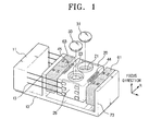
- an optical pickup actuator comprises a holder 11 supported on a base 10, a bobbin 20 having plural lens mounting holes 21, 23 each retaining corresponding one of plural objective lenses 31, 33, in which the plural objective lenses 31, 33 may have working distances different from each other, one or more supporting members (for example, suspensions) 13, and a magnetic circuit for driving the bobbin 20 independently in a focus direction, a tilt direction and a track direction.
- the plural objective lenses 31, 33 comprise a first objective lens 31 for use in recording information into, and/or reproducing information from, one or more low-density optical discs different in recording density, and a second objective lens 33 for use in recording information into, and/or reproducing information from, an optical disc which has a higher recording density than the low-density optical discs (herein below, the optical disc which has a higher recording density is referred to as "high-density optical disc").
- the first objective lens 31 may be provided in such a way that it can additionally record information into, and/or reproduce information from, a CD series optical disc (herein below, "CD") while being capable of recording information into, and/or reproducing information from, for example, a DVD series optical disc (herein below, “DVD”).
- the second objective lens 33 may be provided in such a way that it can record information into, and/or reproduce information from, for example, a HD-DVD series optical disc (herein below, "HD-DVD”), which has a higher density than a DVD.
- the objective lenses 31, 33 may comprise three or more objective lenses so that they can be used in recording information into, and/or reproducing information from, three or more kinds of optical discs which are different in recording density from each other.
- an actuator is arranged in such a way that plural objective lenses 31, 33 can be mounted on one bobbin 30 in the radial direction (R direction) of an optical disc, so as to secure compatibility with an optical pickup that requires plural objective lenses.
- the bobbin 20 can have a first lens mounting hole 21 for receiving a first objective lens 31, and a second lens mounting hole 23 for receiving a second objective lens 33.
- the number of lens mounting holes corresponds to the number of objective lenses to be mounted on the bobbin 20.
- the first and second lens mounting holes 21, 22 are arranged in the R direction.
- the lens holes 21, 23 are formed, for example, in such a way that the objective lenses 31, 33 can be positioned at different heights from each other, as shown in FIG. 4 . That is, the first lens mounting hole 21 may be formed with a seating ridge 21a at a depth relatively deep from the top surface of the bobbin 20 confronting an optical disc, so that the first objective lens 31 having a longer working distance can be mounted for use in a low-density optical disc.
- the second lens mounting hole 23 may be formed with a seating ridge 23a at the level of the top surface of the bobbin 20 confronting an optical disc (or at a position more close to the top surface of the bobbin 20 than the seating ridge 21a formed in the first lens mounting hole 21), so that a second objective lens 33 having a short working distance can be mounted for use in a high-density optical disc.
- the top surface of the bobbin 20 is open through the lens mounting holes 21, 23 and the lower part of the bobbin 20 has a substantially hexahedron shape, which is opened through the coil mounting areas 25, 26.
- the coil mounting areas 25, 26 are divided in the R direction by a central partition 27.
- the coil mounting areas 25, 26 are provided with focusing coils 41, 42 and a tilt coil to be described later within the inner sides thereof.
- the bobbin 20 is movably supported on a holder 11 by the support members 13.
- the support members 13 may be spring wires with a predetermined rigidity, which are elastically deformable.
- the bobbin 20 configured as described above may be formed from a plastic material through an injection molding process.
- the magnetic circuit serves to drive the objective lenses 31, 33 independently in the focus direction, in track direction (herein below, referred to as "R direction"), and in the tilt direction.
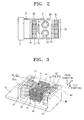
- the magnetic circuit comprises a pair of focusing coils 41, 42, a tilt coil 43, a pair of track coils 44, 45, and first and second polarization magnets 61, 63, as shown in FIGS. 2 to 4 .
- the focusing coils 41, 42 are located adjacent to each other in the R direction. That is, as shown in FIG. 4 , they are installed to be in close contact with the inner walls of the coil mounting areas 25, 26 with the partition 27 being interposed between the focusing coils 41, 42.
- Each of the focusing coils 41, 42 is wound substantially in a rectangular shape to have an air core in the focus direction and to be laminated to a predetermined height in the focus direction.
- the focusing coils 41, 42 are arranged to be wound about the first and second objective lenses 31, 33, respectively.
- the focusing coils 41, 42 will be concurrently forced to drive the bobbin 20 in the focus direction by the cooperation of the sides thereof, which are parallel to each other in the R direction, with the first and second polarization magnets 61, 63.
- These focusing coils 41, 42 are arranged in such a way that electric currents are applied to the focusing coils 41, 42 in the opposite directions, whereby the focusing coils will be forced in the same direction if the electric currents are applied to the focusing coils 41, 42.
- the tilt coil 43 is arranged to be overlapped with the focusing coils 41, 42 in the focus direction. That is, one tilt coil 43 is wound substantially in a rectangular shape and installed to be in close contact with the inner walls of the coil mounting areas 25, 26 of the bobbin 20.
- the tilt coil 43 is provided at a position lower than the focusing coils 41, 42 and formed in a thickness smaller than those of the focusing coils 41, 42 in the focus direction. Therefore, the forces acting in the focus direction will be generated mainly in the focusing coils 41, 42.
- the tilt coil 43 will generate forces opposite to each other with reference to the central position of the bobbin 20 in the R direction, thereby allowing the bobbin 20 to move in the tilt direction.
- the partition 27 is spaced from the bottom end of the bobbin 20 by a predetermined height, so that a mounting space for the tilt coil 43 can be provided.
- the tilt coil 43 receives electric current in a same direction with one of the focusing coils, so that the tilt coil will be forced in the tilt direction. That is, the tilt coil 43 drives the bobbin 20 while being driven independently from the focusing coils 41, 42.
- the track coils 44, 45 are respectively mounted on the external sides of the bobbin 20, which are parallel to the R direction.
- the track coils 44, 45 respectively extend over the interspace between the focusing coils 41, 42 in the R direction. If the track coils 44, 45 respectively extend over the interspace between the focusing coils 41, 42 in this manner, the operation sides of the track coils 44, 45 will be arranged to each face one of the polarized N-pole parts and S-pole parts of the polarization magnet 61, 63, respectively.
- Each of the track coils 44, 45 is wound in a rectangular shape, so that the sides of the track coils 44, 45 parallel to the focus direction face the N-pole parts 61a, 63a and S-pole parts 61b, 63b of the polarization magnets 61, 63, respectively. These track coils 44, 45 will receive forces for driving the bobbin 20 in the track direction through the cooperation with the polarization magnets 61, 63.
- the polarization magnets 61, 63 are spaced from each other and parallel to the R direction of the bobbin 20 with the bobbin 20 being interposed between the polarization magnets 61, 63.
- Each polarization magnet 61; 63 has a first part 61a; 63b and a second part 61b; 63a.
- These polarization magnets 61, 63 are arranged in such a way that both of them participate in driving the bobbin 20 in the focus direction, in the tilt direction and in the track direction and they are commonly used.
- the polarization magnets 61, 63 are arranged in such a way that the corresponding parts of the polarization magnets 61, 63, i.e., the parts confronting each other are same in polarity.
- the polarization magnets 61, 63 are arranged in such a way that they are opposite in polarity to each other diametrically across the bobbin 20.
- the first part 61a of the first polarization magnet 61 and the first part 63a of the second polarization magnet 63 are arranged to be correspondent to each other with the focusing coil 41 being interposed between them.
- the first parts 61a, 63a are arranged in such a way that same poles thereof are facing to each other, thereby causing magnetic flux lines to extend in the opposite directions.
- the first parts 61a, 63a are positioned so that N-poles thereof are facing to each other.
- the second part 61b of the first polarization magnet 61 and the second part 63b of the second polaziation magnet 63 are arranged to confront each other with the focusing coil 42 being interposed between them.
- the second parts 61b, 63b are positioned so that S-poles thereof are facing to each other.
- first magnet section M1 first magnet section M1
- second magnet section M2 second magnet section M2.
- the first and second magnet sections M1, M2 generate an electromagnetic force by cooperating with the focusing coils 41, 42 to drive the bobbin 20 in the focus direction.
- first and second magnet sections M1, M2 generate an electromagnetic force by cooperating with the tilt coil 43 to drive the bobbin 20 in the tilt direction.
- the first and second magnet sections M1, M2 generate an electromagnetic force by cooperating with the track coils to drive the bobbin 20 in the track direction.
- the magnetic circuit further comprises first and second internal yokes 71, 72 located inside of the focusing coils 41, 42, and external yokes 73 located to confront the polarization magnets 61, 63.
- a pair of the first internal yokes 71 are arranged inside of the focusing coil 41.
- the first internal yokes 71 are positioned to confront the effective coil parts of the focusing coil 41 and the tilt coil 43, which confront the first magnet section M1, i.e., the parts parallel to the R direction.
- the first internal yokes 71 may be either affixed to the base 10 or integrally formed with the base 10 in a same metallic material.
- the first internal yokes 71 guide magnetic force lines generated in the focus and tilt directions from the focusing coil 41 and the tilt coil 43 in a state in which the focusing coil 41 and the tilt coil 43 are not in contact with each other, thereby maximizing the intensity of the effective magnetic field.
- the second internal yokes 72 are located within another focusing coil 42 adjacent to the first internal yokes in the R direction.
- the construction and action of the second internal yoke 72 are same with those of the first internal yoke 71, and thus detailed description thereof is omitted.
- the external yokes 73 may be either affixed to or integrally formed with the base 10. These external yokes 73 are positioned to confront the surfaces of the polarization magnets 61, 63 each facing away from the bobbin 20. It is advantageous that the external yokes 73 support the polarization magnets 61, 63. These external yokes 73 guide the electromagnetic force lines of magnetic field generated by the polarization magnets 61, 63 to be focused toward the bobbin 20, thereby maximizing the intensity of the effective magnetic field.
- the polarization magnets 61, 63 are arranged to confront each other with the focusing coils 41, 42 being interposed between them.
- One focusing coil 41 is driven by cooperating with the first magnet section M1 and the other focusing coil 42 is driven by cooperating with the second magnet section M2.
- electric currents are applied to the focusing coils 41, 42 in the opposite directions. Since the faces of the first parts 61a, 63a confronting each other in the first magnet section M1 has N-pole, the magnetic fields produced thereby project in the opposite directions. Since electric currents are applied counterclockwise to the focusing coil 41, the sides of the focusing coil 41 parallel to the R direction are forced upward according to the Fleming's left hand rule.
- the second parts 61b, 63b forming the second magnetic section M2 are arranged so that the S-poles thereof confront one another, the magnetic fields generated in the second parts 61b, 63b are projected in the directions remote from each other, as shown in the drawing. Accordingly, since the electric currents are applied clockwise to the focusing coil 42, the sides of the focusing coil 42 parallel to the R direction are forced upwardly. Consequently, as shown in FIG. 5A , if electric currents are applied to the pair of the focusing coils 41, 42 in the opposite directions, the movable unit comprising the bobbin 20, the first and the second objective lenses 31, 33, the focusing coils 41, 42, the tilt coil 43 and the track coils 44, 45 are moved upwardly.
- FIG. 6A it is possible to upwardly drive the bobbin 20 by applying electric currents to the respective focusing coils 41, 42 as shown in FIG. 5A . Simultaneously with this, electric currents are applied counterclockwise to the tilt coil 43. Then, the tilt coil 43 is forced upwardly in the area corresponding to the first magnet section M2 and forced downwardly in the area corresponding to the second magnet section M2. Accordingly, it is possible to tilt the bobbin 20 to either side independently of the focusing coils 41, 42. That is, in the situation shown in FIG. 6 , the bobbin 20 can be tiltingly driven by the tilt coil 43 by a predetermined angle in the T1 direction, concurrently with being moved upwardly by the focusing coils 41, 42.
- the polarization magnet 61 is bipolarized into N-pole and S-pole.
- the track coil 44 has longer sides in the vertical direction, and the longer sides are arranged to confront the first part 61a of N-pole and the second part 61b of S-pole, respectively.
- the parts confronting the pair of the longer sides of the track coil will be the effective track coil parts which can take part in generation of a magnetic force as electric currents flow in the longer sides in the opposite directions as shown in the drawing. If electric currents are applied counterclockwise to the track coil in this manner, the longer sides are forced in the left direction.
- the other track coil 45 can be controlled in position in the track direction of the bobbin 20 by controlling the polarity and amount of electric currents applied to the track coil 45.
- focusing coils 41, 42 and a tilt coil 43 for controlling a bobbin 20 in the focus and tilt directions are independently installed so that they are capable of being independently driven.
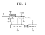
- FIG. 8 schematically shows an optical recording/reproducing apparatus employing the inventive optical pickup actuator.
- the optical recording/producing apparatus comprises a spindle motor 110 for rotating an optical information storage medium, e.g., an optical disc D, an optical pickup 120 installed to be movable in the radial direction R of the optical disc D to reproduce information from/record information into the optical disc D, a driving unit 130 for driving the spindle motor 110 and the optical pickup 120, and a controller 140 for controlling the focusing, tracking and tilt servos of the optical pickup 120.
- reference numeral 122 indicates a turntable
- reference numeral 124 indicates a clamp for chucking an optical disc D.
- the optical pickup 120 comprises an optical system having objective lenses 31, 33 for focusing light projected from a light source into the optical disc, and an optical pickup actuator for three-axis driving of the objective lenses.
- the optical pickup actuator described above with reference to FIGS. 1 to 7b can be employed as the optical pickup actuator.
- the light reflected from the optical disc D is detected by an optical detector provided in the optical pickup 120 and photoelectrically converted into an electric signal.
- the electric signal is inputted into the controller 140 through the driving unit 130.
- the driving unit 130 controls the rotational speed of the spindle motor 110, amplifies the inputted signal and drives the optical pickup 120.
- the controller 140 sends a command concerning the focusing, tracking and tilt servos controlled on the basis of the signal inputted from the driving unit 130 to implement the focusing, tracking and tilt movement of the optical pickup 120.
- a bobbin 20 with a construction for mounting more than two objective lenses, so that the bobbin 20 can be applied to an optical pickup capable of compatibly recording/reducing two, three or more types of optical discs which are different in record density, for example, a CD, a DVD and a HD-DVD.
- an inventive optical pickup actuator comprises a single bobbin mounted with two objective lenses, so that the objective lenses can be independently and simultaneously controlled in the focus, tilt and track directions.
- the sensitivity and adaptive performance at a high speed can be improved.
- An optical pickup actuator can be adaptively employed to a high speed optical recording/reproducing apparatus.
- Several exemplary embodiments of the present invention have been shown and described in order to exemplify the principles of the present invention, but the present invention is not limited to the specific embodiments. It will be understood that various modifications and changes can be made by one skilled in the art without departing from the scope of the invention as defined by the appended claims. Therefore, it shall be considered that such modifications, changes and equivalents thereof are all included within the scope of the present invention.
Description
- The present invention relates to an optical pickup actuator and an optical recording/reproducing apparatus. In particular, but not exclusively, the present invention relates to an optical pickup actuator for driving an objective lens mounted on the actuator in such a way that information can be recorded into, and reproduced from, an optical information storage medium, and an optical recording/reproducing apparatus having the same.
- Conventionally, a Digital Versatile Disk (DVD) is recorded/reproduced using an objective lens having a numerical aperture of 0.6 (in a recordable type, 0.65) and a light having a wavelength of 650 nm (or 635 nm). If such a DVD has a diameter of 120 mm and a track pitch of 0.75 µm, the DVD has a recording capacity of not less than 4.7 GB on one side thereof.
- Therefore, such a DVD is not sufficient as a recording medium for recording moving image information of an HD (High Definition) grade, because a recording capacity of, for example, not less than 23 GB on one side of a DVD is required to record 135 minutes of moving image information in the HD grade.
- In order to meet such a requirement for high-density record capacity, development and standardization for High Definition-DVD (HD-DVD), that is, next generation DVD are proceeding. The developments include using a light having a shorter wavelength than red color (that is, a blue light), employing an objective lens having a numerical aperture larger than 0.6, and having a narrower track.
- In order to maintain a tolerance due to a tilt of an optical disc, the thickness of the optical disc may be reduced as the numerical aperture of an objective lens is increased for obtaining a high density. In consideration of an allowed tolerance due to a tilt of an optical disc, the thickness has been reduced from 1.2 mm for Compact Discs (CD's) to 0.6 mm for DVD's. For HD-DVD's, it is highly feasible for the thickness to be 0.1 mm. The numerical aperture of an objective lens has been increased from 0.45 (for CD's) to 0.6 (for DVD's). For HD-DVD's, it is highly feasible for the numerical aperture to be 0.85. In addition, it is highly feasible for a celadon light source to be employed as a light source for HD-DVD's in consideration of a record capacity. A problem encountered in developing optical discs of a new standard as described above is compatibility with existing optical discs.
- However, a fairly sophisticated technique is required in developing and fabricating a one-piece objective lens having a high numerical aperture, for example 0.85. Furthermore, it is difficult to lengthen a working distance of such an objective lens to a distance suitable for an objective lens for a DVD, while allowing the objective lens to have such a high numerical aperture.
- Therefore, it is required for a compatible type optical pickup capable of high-density recording/reproduction to separately include at least one objective lens for use in recording/reproducing a CD and/or a DVD and an objective lens for use in high-density recording, wherein the objective lens for use in high-density recording has a higher numerical aperture than the objective lens for use in recording a CD and/or a DVD, so as to address the problem of having proper working distance.
- Meanwhile, since an actuator for such an optical pickup has a magnetic circuit configured in such a way that the actuator can be driven in both focus and track directions, the actuator serves to maintain the distance between an optical disc and an objective lens constant and to move the objective lens to a desired position (center of the track) in the track direction.
- In order to address optical pickup compatibly when employing plural optical discs of different recording density, as described above, it is necessary to provide plural objective lenses each corresponding to one of plural optical discs of different recording capacity.
-
EP1394783 discloses an objective lens driving apparatus for an optical pickup includes a base, a holder provided on the base, a blade on which an objective lens is mounted, an elastic support body elastically supporting the blade capable of moving with respect to the holder, a pair of magnetic members installed on the base to face each other, and a coil assembly including a focus coil, a tracking coil, and a tilt coil and installed at the blade so as to be disposed between the magnetic members. -
US 2004/240335 discloses an optical pickup actuator and optical disc drive using the same. The optical pickup actuator includes a bobbin holding an objective lens and supported on a base by a plurality of suspension wires so that it is elastically movable, a magnetic element positioned on the base, and a coil positioned horizontally on the bobbin to generate electromagnetic force in a focusing direction and/or a tilting direction through interaction with the magnetic element. The coil is divided into a plurality of subcoils separated vertically from one another. The optical pickup actuator further includes a second coil positioned vertically on either one or two sides of the bobbin in a second direction perpendicular to the first direction, the second coil generating an electromagnetic force in a tracking direction through interaction with the magnetic element. - Accordingly, an actuator applied to an optical pickup having plural objective lenses requires a magnetic circuit that can drive at least one of the plural objective lenses mounted on a movable part in focus, track and tilt directions while maintaining high sensitivity. Thus, complexity of construction is increased to meet the demands of HD-DVD.
- Embodiments of the present invention have been made to address the above-mentioned problems, and an object of embodiments of the present invention is to provide an optical pickup actuator improved to maintain high sensitivity with a simple construction and an optical recording/reproducing apparatus having the same.
- According to a first aspect of the present invention, there is provided an optical pickup actuator comprising:
- a bobbin comprising at least one objective lens mounted on a top surface of the bobbin for allowing light to be incident onto an optical information storage medium;
- a movable support member for supporting the bobbin; and
- a magnetic circuit comprising:
- a pair of focusing coils adjacent to each other in the bobbin in the track direction and disposed beneath the at least one objective lens;
- a tilt coil comprising working sides corresponding to working sides of the focusing coils, respectively; and
- at least one magnet section for generating a driving force in a focusing direction by cooperating with the focusing coils, and for generating a driving force in a tilt direction by cooperating with the tilt coil ; and
- the pair of focusing coils are configured to receive electric currents, wherein the electric current in a first focus coil flows in the opposite direction to the electric current in a second focus coil, and the tilt coil is configured to receive electric current in a same direction with one of the focusing coils to achieve a driving force in the desired tilt direction; and wherein
- the focusing coils are positioned higher than the tilt coil in reference to the focusing direction.
- According to another aspect of the present invention, there is also provided an optical recording/reproducing apparatus comprising an optical pickup according to the first aspect installed to be movable in the radial direction of an optical information storage medium to record information into, and/or reproduce information from, the optical information storage medium, and a controller for controlling focusing, track and tilt servos.
- The above aspects and features of the present invention will be more apparent from the description for certain exemplary embodiments of the present invention taken with reference to the accompanying drawings, in which the same or similar elements, features and structures are represented by the same reference numerals, wherein:
-
FIG. 1 is a schematic exploded perspective view showing an optical pickup actuator according to an embodiment of the present invention; -
FIG. 2 is a top plan view of the optical pickup actuator shown inFIG. 1 ; -
FIG. 3 is a perspective view showing a magnetic circuit according to an exemplary embodiment of the present invention, in which a bobbin is removed from the state shown inFIG. 1 ; -
FIG. 4 is a cross-sectional view of the bobbin extracted fromFIG. 1 ; -
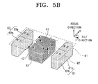
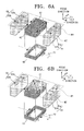
FIGS. 5A and5B illustrate an operation for driving the bobbin in a focus direction according to an exemplary embodiment of the present invention; -
FIGS. 6A and 6B illustrate operations for driving the bobbin in a focus direction and a tilt direction, respectively, according to an exemplary embodiment of the present invention; -
FIGS. 7A and 7B illustrate an operation for driving the bobbin in a track direction according to an exemplary embodiment of the present invention; and -
FIG. 8 is a schematic diagram showing an optical recording/reproducing apparatus according to an exemplary embodiment of the present invention. - Herein below, optical pickup actuators according to exemplary embodiments of the present invention are described in detail with reference to accompanying drawings.
- Referring to
FIG. 1 , an optical pickup actuator according to an embodiment of the present invention comprises aholder 11 supported on abase 10, abobbin 20 having plurallens mounting holes objective lenses objective lenses bobbin 20 independently in a focus direction, a tilt direction and a track direction. - The plural
objective lenses objective lens 31 for use in recording information into, and/or reproducing information from, one or more low-density optical discs different in recording density, and a secondobjective lens 33 for use in recording information into, and/or reproducing information from, an optical disc which has a higher recording density than the low-density optical discs (herein below, the optical disc which has a higher recording density is referred to as "high-density optical disc"). The firstobjective lens 31 may be provided in such a way that it can additionally record information into, and/or reproduce information from, a CD series optical disc (herein below, "CD") while being capable of recording information into, and/or reproducing information from, for example, a DVD series optical disc (herein below, "DVD"). The secondobjective lens 33 may be provided in such a way that it can record information into, and/or reproduce information from, for example, a HD-DVD series optical disc (herein below, "HD-DVD"), which has a higher density than a DVD. Here, theobjective lenses - According to an exemplary implementation of the present invention, an actuator is arranged in such a way that plural
objective lenses - If the
bobbin 20 has a construction for mounting twoobjective lenses bobbin 20 can have a firstlens mounting hole 21 for receiving a firstobjective lens 31, and a secondlens mounting hole 23 for receiving a secondobjective lens 33. Here, the number of lens mounting holes corresponds to the number of objective lenses to be mounted on thebobbin 20. - The first and second
lens mounting holes 21, 22 are arranged in the R direction. In addition, thelens holes objective lenses FIG. 4 . That is, the firstlens mounting hole 21 may be formed with aseating ridge 21a at a depth relatively deep from the top surface of thebobbin 20 confronting an optical disc, so that the firstobjective lens 31 having a longer working distance can be mounted for use in a low-density optical disc. The secondlens mounting hole 23 may be formed with aseating ridge 23a at the level of the top surface of thebobbin 20 confronting an optical disc (or at a position more close to the top surface of thebobbin 20 than theseating ridge 21a formed in the first lens mounting hole 21), so that a secondobjective lens 33 having a short working distance can be mounted for use in a high-density optical disc. - According to an exemplary implementation of the present invention, the top surface of the
bobbin 20 is open through thelens mounting holes bobbin 20 has a substantially hexahedron shape, which is opened through thecoil mounting areas coil mounting areas central partition 27. Thecoil mounting areas coils - The
bobbin 20 is movably supported on aholder 11 by thesupport members 13. Thesupport members 13 may be spring wires with a predetermined rigidity, which are elastically deformable. On each of the front and rear sides of thebobbin 20, there may be provided aconnection board 28, to which thesupport members 13 are affixed through soldering or the like. Therefore, it is possible to deliver electric currents to the magnetic circuit through thesupport members 13. Thebobbin 20 configured as described above may be formed from a plastic material through an injection molding process. - The magnetic circuit serves to drive the
objective lenses coils tilt coil 43, a pair of track coils 44, 45, and first andsecond polarization magnets FIGS. 2 to 4 . - The focusing coils 41, 42 are located adjacent to each other in the R direction. That is, as shown in
FIG. 4 , they are installed to be in close contact with the inner walls of thecoil mounting areas partition 27 being interposed between the focusing coils 41, 42. Each of the focusing coils 41, 42 is wound substantially in a rectangular shape to have an air core in the focus direction and to be laminated to a predetermined height in the focus direction. In addition, the focusing coils 41, 42 are arranged to be wound about the first and secondobjective lenses - The focusing coils 41, 42 will be concurrently forced to drive the
bobbin 20 in the focus direction by the cooperation of the sides thereof, which are parallel to each other in the R direction, with the first andsecond polarization magnets - The
tilt coil 43 is arranged to be overlapped with the focusing coils 41, 42 in the focus direction. That is, onetilt coil 43 is wound substantially in a rectangular shape and installed to be in close contact with the inner walls of thecoil mounting areas bobbin 20. Thetilt coil 43 is provided at a position lower than the focusing coils 41, 42 and formed in a thickness smaller than those of the focusing coils 41, 42 in the focus direction. Therefore, the forces acting in the focus direction will be generated mainly in the focusing coils 41, 42. In addition, thetilt coil 43 will generate forces opposite to each other with reference to the central position of thebobbin 20 in the R direction, thereby allowing thebobbin 20 to move in the tilt direction. - According to an exemplary implementation of the present invention, since the
tilt coil 43 is arranged over thecoil mounting areas partition 27 is spaced from the bottom end of thebobbin 20 by a predetermined height, so that a mounting space for thetilt coil 43 can be provided. - The
tilt coil 43 receives electric current in a same direction with one of the focusing coils, so that the tilt coil will be forced in the tilt direction. That is, thetilt coil 43 drives thebobbin 20 while being driven independently from the focusing coils 41, 42. - The track coils 44, 45 are respectively mounted on the external sides of the
bobbin 20, which are parallel to the R direction. The track coils 44, 45 respectively extend over the interspace between the focusing coils 41, 42 in the R direction. If the track coils 44, 45 respectively extend over the interspace between the focusing coils 41, 42 in this manner, the operation sides of the track coils 44, 45 will be arranged to each face one of the polarized N-pole parts and S-pole parts of thepolarization magnet pole parts pole parts polarization magnets bobbin 20 in the track direction through the cooperation with thepolarization magnets - The
polarization magnets bobbin 20 with thebobbin 20 being interposed between thepolarization magnets polarization magnet 61; 63 has afirst part 61a; 63b and asecond part 61b; 63a. Thesepolarization magnets bobbin 20 in the focus direction, in the tilt direction and in the track direction and they are commonly used. For this purpose, thepolarization magnets polarization magnets polarization magnets bobbin 20. - According to an exemplary implementation of the present invention, the
first part 61a of thefirst polarization magnet 61 and thefirst part 63a of thesecond polarization magnet 63 are arranged to be correspondent to each other with the focusingcoil 41 being interposed between them. In addition, thefirst parts first parts - According to an exemplary implementation of the present invention, the
second part 61b of thefirst polarization magnet 61 and thesecond part 63b of thesecond polaziation magnet 63 are arranged to confront each other with the focusingcoil 42 being interposed between them. Thesecond parts - For the convenience of description, herein below, the
first parts polarization magnets second parts bobbin 20 in the focus direction. - In addition, the first and second magnet sections M1, M2 generate an electromagnetic force by cooperating with the
tilt coil 43 to drive thebobbin 20 in the tilt direction. The first and second magnet sections M1, M2 generate an electromagnetic force by cooperating with the track coils to drive thebobbin 20 in the track direction. These driving actions will be described later. - The magnetic circuit further comprises first and second
internal yokes external yokes 73 located to confront thepolarization magnets - A pair of the first
internal yokes 71 are arranged inside of the focusingcoil 41. The firstinternal yokes 71 are positioned to confront the effective coil parts of the focusingcoil 41 and thetilt coil 43, which confront the first magnet section M1, i.e., the parts parallel to the R direction. The firstinternal yokes 71 may be either affixed to the base 10 or integrally formed with the base 10 in a same metallic material. The firstinternal yokes 71 guide magnetic force lines generated in the focus and tilt directions from the focusingcoil 41 and thetilt coil 43 in a state in which the focusingcoil 41 and thetilt coil 43 are not in contact with each other, thereby maximizing the intensity of the effective magnetic field.
The secondinternal yokes 72 are located within another focusingcoil 42 adjacent to the first internal yokes in the R direction. The construction and action of the secondinternal yoke 72 are same with those of the firstinternal yoke 71, and thus detailed description thereof is omitted. - The
external yokes 73 may be either affixed to or integrally formed with thebase 10. Theseexternal yokes 73 are positioned to confront the surfaces of thepolarization magnets bobbin 20. It is advantageous that theexternal yokes 73 support thepolarization magnets external yokes 73 guide the electromagnetic force lines of magnetic field generated by thepolarization magnets bobbin 20, thereby maximizing the intensity of the effective magnetic field. - Now, the functional effect of the optical pickup actuator according to the above-described exemplary embodiment of the present invention is described in detail.
- At first, the direction of a driving force generated by the cooperation of the second focusing
coils - As shown in
FIG. 5A , thepolarization magnets coil 41 is driven by cooperating with the first magnet section M1 and the other focusingcoil 42 is driven by cooperating with the second magnet section M2. As shown in the drawing, electric currents are applied to the focusing coils 41, 42 in the opposite directions. Since the faces of thefirst parts coil 41, the sides of the focusingcoil 41 parallel to the R direction are forced upward according to the Fleming's left hand rule. In addition, since thesecond parts second parts coil 42, the sides of the focusingcoil 42 parallel to the R direction are forced upwardly. Consequently, as shown inFIG. 5A , if electric currents are applied to the pair of the focusing coils 41, 42 in the opposite directions, the movable unit comprising thebobbin 20, the first and the secondobjective lenses tilt coil 43 and the track coils 44, 45 are moved upwardly. - Referring to
FIG. 5B , electric currents are applied to the focusing coils 41, 42 in the reversed sense in relation to the situation shown inFIG. 5A . In this event, the sides of the respective focusingcoils objective lenses bobbin 20 can be controlled to different positions. - Referring to
FIG. 6A , it is possible to upwardly drive thebobbin 20 by applying electric currents to the respective focusingcoils FIG. 5A . Simultaneously with this, electric currents are applied counterclockwise to thetilt coil 43. Then, thetilt coil 43 is forced upwardly in the area corresponding to the first magnet section M2 and forced downwardly in the area corresponding to the second magnet section M2. Accordingly, it is possible to tilt thebobbin 20 to either side independently of the focusing coils 41, 42. That is, in the situation shown inFIG. 6 , thebobbin 20 can be tiltingly driven by thetilt coil 43 by a predetermined angle in the T1 direction, concurrently with being moved upwardly by the focusing coils 41, 42. - In contrast, as shown in
FIG. 6B , by applying electric currents to the focusing coils 41, 42 in a same direction as described with reference toFIG. 5 , it is possible to focus thebobbin 20 downwardly. Under this condition, electric currents are applied clockwise to thetilt coil 43. Then, thetilt coil 43 is forced downwardly in the area corresponding to the first magnet section M1 and forced upwardly in the area corresponding to the second magnet section M2. Therefore, thebobbin 20 is tilted in the T2 direction by the tilt coil, concurrently with being moved downwardly by the focusing coils 41, 42. - Accordingly, it is possible to control the driving of the first and second
objective lenses bobbin 20 in the tilt direction, by applying electric currents to the respective focusingcoils tilt coil 43. Likewise, it is possible to tilt thebobbin 20 by applying electric currents only to the tilt coil without applying electric currents to the focusing coils 41, 42. - Below, the driven movement of the
bobbin 20 in the track direction by the cooperation between the respective track coils 44, 45 and therespective polarization magnets - As shown in
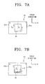
FIG. 7A , thepolarization magnet 61 is bipolarized into N-pole and S-pole. In this state, thetrack coil 44 has longer sides in the vertical direction, and the longer sides are arranged to confront thefirst part 61a of N-pole and thesecond part 61b of S-pole, respectively. In this state, assuming that the magnetic field coming out from thefirst part 61a projects in the direction vertical to the surface of the drawing, the parts confronting the pair of the longer sides of the track coil will be the effective track coil parts which can take part in generation of a magnetic force as electric currents flow in the longer sides in the opposite directions as shown in the drawing. If electric currents are applied counterclockwise to the track coil in this manner, the longer sides are forced in the left direction. - In addition, as shown in
FIG. 7B , if electric currents flow clockwise in thetrack coil 44, the longer sides of thetrack coil 44 are forced in the right direction. Like this, depending on the polarity and amount of the electric currents applied to thetrack coil 44, it is possible to drivingly control the first and secondobjective lenses bobbin 20 in the track direction (R direction). - Since the forces to be acted on the
track coil 45 by the cooperation between thetrack coil 45 and thesecond polarization magnet 63, which confront each other, can be sufficiently appreciated from the description made above with reference toFIGS. 7a and 7b , detailed description is omitted. That is, theother track coil 45 can be controlled in position in the track direction of thebobbin 20 by controlling the polarity and amount of electric currents applied to thetrack coil 45. - As described above, in an actuator according to an exemplary implementation of the present invention, focusing
coils tilt coil 43 for controlling abobbin 20 in the focus and tilt directions are independently installed so that they are capable of being independently driven. - As a result, it is possible to improve the adaptive performance of an optical pickup for making objective lenses to be adapted to a system as well as the sensitivity of the optical pickup.
- In addition, by installing the focusing coils and the tilt coil to be in close contact with the inner sides of the bobbin, it is possible to reinforce the strength of an injection-molded bobbin. Accordingly, it is possible to sufficiently secure the movement and increase sensitivity in a high-speed rotation.
-
FIG. 8 schematically shows an optical recording/reproducing apparatus employing the inventive optical pickup actuator. - Referring to
FIG. 8 , the optical recording/producing apparatus comprises aspindle motor 110 for rotating an optical information storage medium, e.g., an optical disc D, anoptical pickup 120 installed to be movable in the radial direction R of the optical disc D to reproduce information from/record information into the optical disc D, adriving unit 130 for driving thespindle motor 110 and theoptical pickup 120, and acontroller 140 for controlling the focusing, tracking and tilt servos of theoptical pickup 120. Here,reference numeral 122 indicates a turntable, andreference numeral 124 indicates a clamp for chucking an optical disc D. - The
optical pickup 120 comprises an optical system havingobjective lenses FIGS. 1 to 7b can be employed as the optical pickup actuator. - The light reflected from the optical disc D is detected by an optical detector provided in the
optical pickup 120 and photoelectrically converted into an electric signal. The electric signal is inputted into thecontroller 140 through the drivingunit 130. The drivingunit 130 controls the rotational speed of thespindle motor 110, amplifies the inputted signal and drives theoptical pickup 120. - The
controller 140 sends a command concerning the focusing, tracking and tilt servos controlled on the basis of the signal inputted from the drivingunit 130 to implement the focusing, tracking and tilt movement of theoptical pickup 120. - Although it has been stated that two objective lenses are mounted on one
bobbin 20, this is merely an example. That is, although there are provided twolens mounting holes bobbin 20, only one lens mounting hole may have one objective lens to be used. In this event, the one objective lens can be easily adjusted using the above-mentioned magnetic circuit. - Furthermore, it is also possible to provide a
bobbin 20 with a construction for mounting more than two objective lenses, so that thebobbin 20 can be applied to an optical pickup capable of compatibly recording/reducing two, three or more types of optical discs which are different in record density, for example, a CD, a DVD and a HD-DVD. - As described above, an inventive optical pickup actuator according to an exemplary implementation of the present invention comprises a single bobbin mounted with two objective lenses, so that the objective lenses can be independently and simultaneously controlled in the focus, tilt and track directions.
- Accordingly, the sensitivity and adaptive performance at a high speed can be improved.
- In addition, it is possible to reinforce a bobbin formed through injection molding by installing focusing coils and a tilt coil, which are independently driven, to be in close contact with the inner walls of the bobbin.
Consequently, it is possible to sufficiently secure a movement of a secondary resonance frequency to a higher area and a gain margin, wherein the secondary resonance frequency is produced by a physical characteristic of a bobbin. - An optical pickup actuator according to an exemplary implementation of the present invention can be adaptively employed to a high speed optical recording/reproducing apparatus.
Several exemplary embodiments of the present invention have been shown and described in order to exemplify the principles of the present invention, but the present invention is not limited to the specific embodiments. It will be understood that various modifications and changes can be made by one skilled in the art without departing from the scope of the invention as defined by the appended claims. Therefore, it shall be considered that such modifications, changes and equivalents thereof are all included within the scope of the present invention.
Claims (26)
- An optical pickup actuator comprising:a bobbin (20) comprising at least one objective lens (31) mounted on a top surface of the bobbin (20) for allowing light to be incident onto an optical information storage medium (D);a movable support member (13) for supporting the bobbin; anda magnetic circuit comprising:a pair of focusing coils (41, 42) adjacent to each other in the bobbin (20) in the track direction (R) and disposed beneath the at least one objective lens;a tilt coil (43) comprising working sides corresponding to working sides of the focusing coils (41, 42), respectively; andat least one magnet section (M1) for generating a driving force in a focusing direction by cooperating with the focusing coils (41, 42), and for generating a driving force in a tilt direction by cooperating with the tilt coil (43); andthe pair of focusing coils (41, 42) are configured to receive electric currents, wherein the electric current in a first focus coil flows in the opposite direction to the electric current in a second focus coil, and the tilt coil (43) is configured to receive electric current in a same direction with one of the focusing coils to achieve a driving force in the desired tilt direction; and whereinthe focusing coils (41, 42) are positioned above the tilt coil (43) in reference to the focusing direction.
- An optical pickup actuator as claimed in claim 1, wherein the magnet section comprises:a first magnet section (M1), in which the bobbin is interposed; anda second magnet section (M2) arranged adjacent to the first magnet section (M1), wherein the second magnet section is opposite in polarity to the first magnet section diametrically across the bobbin; and whereinthe focusing coils (41, 42) are positioned above the tilt coil (43) in reference to the focusing direction.
- An optical pickup actuator as claimed in claim 2, wherein each of the first and second magnet sections comprises a pair of polarization magnets (61, 63) arranged to confront each other with the bobbin being interposed between the pair of polarization magnets, wherein the polarization magnets are depolarized in the direction parallel to the working sides of the focusing coils.
- An optical pickup actuator as claimed in any of claims 1-3, wherein the pair of focusing coils (41, 42) are arranged parallel to the track direction (R), wherein the track direction (R) crosses the focusing direction.
- An optical pickup actuator as claimed in any of claims 1-4, wherein the focusing coils (41, 42) and the tilt coil (43) are arranged to be overlapped with each other in the focusing direction.
- An optical pickup actuator as claimed in any of claims 1-5, wherein the focusing coils (41, 42) comprise a larger thickness than the tilt coil (43) in the focusing direction.
- An optical pickup actuator as claimed in any of claims 1-6, wherein the magnetic circuit further comprises:at least one internal yoke (71) inside of the focusing coils (41, 42) and the tilt coil (43); andat least one external yoke (73) outside of the focusing coils and tilt coil.
- An optical pickup actuator as claimed in claim 7, further comprising a base (10), wherein the at least one external yoke (73) is provided on the base to support the magnet sections.
- An optical pickup actuator as claimed in claim 7 or 8, wherein the at least one internal (71) yoke comprises:a pair of first internal yokes (71) arranged to confront the sides of the focusing coils and the tilt coil, the sides being parallel to the track direction (R); anda pair of second internal yokes (72) adjacent to the first internal yokes (71) in the track direction (R) and arranged to confront the working sides of the focusing coils and the tilt coil.
- An optical pickup actuator as claimed in any preceding claim, wherein the bobbin (20) comprises plural lens mounting holes (21, 23) arranged in the track direction (R), whereby the bobbin is arranged to accommodate plural objective lenses (31, 33).
- An optical pickup actuator as claimed in claim 10, wherein the bobbin (20) comprises a pair of lens mounting holes (21, 23), and wherein the magnetic circuit comprises:a pair of focusing coils (41, 42) wound about the lens mounting holes (21, 23), respectively;a tilt coil (43) wound to surround the pair of lens mounting holes; andat least one magnet section (M1) for generating at least one of a driving force in the focusing direction by cooperating with the focusing coils (41, 42), and a driving force in the tilt direction by cooperating with the tilt coil (43).
- An optical pickup actuator as claimed in claim 11, wherein the bobbin (20) comprises a coil mounting area (25) beneath the lens mounting holes, and wherein the coil mounting area receives the focusing coils and the tilt coil adjacent to each other in the track direction (R).
- An optical pickup actuator as claimed in claim 12, wherein the focusing coils (41, 42) and the tilt coil (43) are arranged adjacent to each other in the focusing direction.
- An optical pickup actuator as claimed in any of claims 1-13, wherein the bobbin (20) comprises a coil mounting area (25) for supporting the focusing coils and the tilt coil on the inner walls thereof.
- An optical pickup actuator as claimed in claim 14, wherein the coil mounting area (25) comprises a partition (27) interposed between the focusing coils (41, 42) to isolate them.
- An optical pickup actuator as claimed in any of claims 1-15, wherein the magnetic circuit further comprises a pair of track coils (44, 45) for driving the bobbin in the track direction (R) by cooperating with the magnet sections.
- An optical pickup actuator as claimed in claim 16, wherein the track coils (44, 45) are supported on the external surfaces of the bobbin respectively confronting the magnet sections, the track coils being installed between the focusing coils (41, 42) in the track direction (R).
- An optical pickup actuator as claimed in claim 17, wherein the track coils (44, 45) are arranged to comprise sides parallel to the focusing direction among sides confronting the magnet sections.
- The optical pickup actuator according to any preceding claim, wherein the optical pickup actuator comprising:the bobbin (20) is configured to accommodate a plurality of objective lenses (31, 33) for at least one of recording information into optical information record media which are different from each other in record density and reproducing information from the optical information record media.
- An optical pickup actuator as claimed in claim 19, wherein the magnetic circuit comprises:a plurality of focusing coils (41, 42) supported in the bobbin and correspond to the plurality of the objective lenses (31, 33), respectively;at least one tilt coil (43) installed in the bobbin to correspond and corresponding to the plurality of the objective lenses; anda pair of polarization magnets (61, 63) arranged to confront each other with the bobbin being interposed between the polarization magnets;wherein each one of the polarization magnets (61, 63) comprise a first part arranged to be adjacent to a second part in the track direction (R), wherein a north and south pole of the first part is arranged to be adjacent a south pole and a north pole of the second part, respectively.
- An optical pickup actuator as claimed in claim 20, wherein the focus coils and the tilt coil are overlapped with each other in the focusing direction.
- An optical pickup actuator as claimed in claim 20 or 21, wherein the polarization magnets are arranged to be opposite, in the direction of magnetic fluxes, to each other, with the focusing coils being interposed between the polarization magnets.
- An optical pickup actuator as claimed in claim 20, 21 or 22, wherein the magnetic circuit further comprises:a pair of track coils (44, 45) mounted on the surfaces of the bobbin confronting the polarization magnets to drive the bobbin in the track direction (R).
- An optical pickup actuator as claimed in claim 23, wherein the track coils (44, 45) are positioned at the central position between the focusing coils in the focusing direction.
- An optical pickup actuator as claimed in any of claims 20-24, further comprising a base (10), wherein the magnetic circuit comprises:external yokes (73) provided on the base (10) to support the polarization magnets (61, 63); andplural internal yokes (71, 72) provided on the base and positioned within the focusing coils (41, 42).
- An optical recording/reproducing apparatus comprising:an optical pickup according to any one of claims 1-25 installed to be movable in the radial direction of an optical information storage medium (D) for at least one of recording information into the optical information storage medium and reproducing information from the optical information storage medium; anda controller (140) for controlling focusing, track and tilt servos.
Applications Claiming Priority (1)
| Application Number | Priority Date | Filing Date | Title |
|---|---|---|---|
| KR1020040110311A KR100710753B1 (en) | 2004-12-22 | 2004-12-22 | An actuator for optical pick-up and optical recording/reproducing apparatus having the same |
Publications (3)
| Publication Number | Publication Date |
|---|---|
| EP1675111A2 EP1675111A2 (en) | 2006-06-28 |
| EP1675111A3 EP1675111A3 (en) | 2006-10-04 |
| EP1675111B1 true EP1675111B1 (en) | 2009-03-04 |
Family
ID=36117690
Family Applications (1)
| Application Number | Title | Priority Date | Filing Date |
|---|---|---|---|
| EP05257570A Expired - Fee Related EP1675111B1 (en) | 2004-12-22 | 2005-12-08 | Optical pickup actuator and optical recording/reproducing apparatus |
Country Status (5)
| Country | Link |
|---|---|
| US (1) | US7668049B2 (en) |
| EP (1) | EP1675111B1 (en) |
| KR (1) | KR100710753B1 (en) |
| CN (1) | CN100399439C (en) |
| DE (1) | DE602005013050D1 (en) |
Families Citing this family (5)
| Publication number | Priority date | Publication date | Assignee | Title |
|---|---|---|---|---|
| KR100689042B1 (en) * | 2005-04-20 | 2007-03-09 | 삼성전자주식회사 | An actuator for optical pick-up and optical recording/reproducing apparatus having the same |
| TW200707431A (en) * | 2005-08-12 | 2007-02-16 | Lite On It Corp | Actuator of optical pickup head with horizontal-arranged magnetic field generator and coil apparatus |
| JP4522388B2 (en) * | 2006-04-03 | 2010-08-11 | 三洋電機株式会社 | Objective lens driving device and optical pickup device having the same |
| CN208027061U (en) * | 2016-07-01 | 2018-10-30 | 台湾东电化股份有限公司 | More camera lens photographic systems |
| CN112543887B (en) * | 2018-05-23 | 2022-08-19 | Lg伊诺特有限公司 | Lens driving device, camera module and optical apparatus including the same |
Family Cites Families (19)
| Publication number | Priority date | Publication date | Assignee | Title |
|---|---|---|---|---|
| JPH04205821A (en) * | 1990-11-30 | 1992-07-28 | Hitachi Ltd | Objective lens drive device |
| US5673247A (en) * | 1995-11-29 | 1997-09-30 | Sharp Kabushiki Kaisha | Optical pickup having two objective lenses |
| JPH09171630A (en) | 1995-12-20 | 1997-06-30 | Akai Electric Co Ltd | Objective support device for optical pickup |
| JP3541617B2 (en) * | 1997-04-23 | 2004-07-14 | 日本ビクター株式会社 | Optical disk drive |
| KR100636103B1 (en) * | 1999-10-21 | 2006-10-18 | 삼성전자주식회사 | Optical pickup assembly |
| KR100727911B1 (en) * | 2000-12-08 | 2007-06-14 | 삼성전자주식회사 | Four axies driving actuator for optical pickup |
| JP3890941B2 (en) * | 2001-10-02 | 2007-03-07 | 日本電気株式会社 | Objective lens drive |
| JP2003141760A (en) | 2001-10-31 | 2003-05-16 | Sumida Corporation | Optical pickup |
| KR100636127B1 (en) * | 2001-12-01 | 2006-10-19 | 삼성전자주식회사 | Actuator for optical pickup |
| JP2003173556A (en) | 2001-12-07 | 2003-06-20 | Tdk Corp | Optical head device |
| TW200405314A (en) | 2002-08-24 | 2004-04-01 | Samsung Electronics Co Ltd | Objective lens driving apparatus for optical pickup |
| KR20040037893A (en) * | 2002-10-30 | 2004-05-08 | 삼성전자주식회사 | Actuator for optical pickup, optical pickup apparatus and optical recording/ reproducing apparatus adopting the same |
| JP2004213861A (en) * | 2002-12-20 | 2004-07-29 | Sharp Corp | Objective lens drive device and optical pickup device |
| JP3567931B2 (en) | 2003-01-20 | 2004-09-22 | 三菱電機株式会社 | Optical information device |
| US20040268373A1 (en) * | 2003-01-29 | 2004-12-30 | Samsung Electronics Co., Ltd. | Tilt drive optical pickup actuator and optical recording and/or reproducing apparatus using the same and method |
| KR100505673B1 (en) * | 2003-02-21 | 2005-08-03 | 삼성전자주식회사 | Optical pickup actuator capable of driving tilt and optical recording and/or reproducing apparatus employing it |
| JP3821105B2 (en) * | 2003-02-28 | 2006-09-13 | 三菱電機株式会社 | Optical means driving device |
| KR100505687B1 (en) * | 2003-06-02 | 2005-08-03 | 삼성전자주식회사 | Optical pickup actuator and optical disc drive adopting the same |
| KR100522232B1 (en) * | 2003-12-24 | 2005-10-17 | 엘지전자 주식회사 | Optical pick-up actuator of slim type |
-
2004
- 2004-12-22 KR KR1020040110311A patent/KR100710753B1/en not_active IP Right Cessation
-
2005
- 2005-11-14 CN CNB2005101153062A patent/CN100399439C/en not_active Expired - Fee Related
- 2005-12-08 EP EP05257570A patent/EP1675111B1/en not_active Expired - Fee Related
- 2005-12-08 DE DE602005013050T patent/DE602005013050D1/en active Active
- 2005-12-20 US US11/311,350 patent/US7668049B2/en not_active Expired - Fee Related
Also Published As
| Publication number | Publication date |
|---|---|
| DE602005013050D1 (en) | 2009-04-16 |
| KR100710753B1 (en) | 2007-04-24 |
| CN1794348A (en) | 2006-06-28 |
| KR20060071648A (en) | 2006-06-27 |
| US7668049B2 (en) | 2010-02-23 |
| EP1675111A3 (en) | 2006-10-04 |
| EP1675111A2 (en) | 2006-06-28 |
| US20060136953A1 (en) | 2006-06-22 |
| CN100399439C (en) | 2008-07-02 |
Similar Documents
| Publication | Publication Date | Title |
|---|---|---|
| KR100636127B1 (en) | Actuator for optical pickup | |
| KR100498443B1 (en) | Actuator used for optical pickup | |
| EP1675111B1 (en) | Optical pickup actuator and optical recording/reproducing apparatus | |
| KR100689042B1 (en) | An actuator for optical pick-up and optical recording/reproducing apparatus having the same | |
| US7458086B2 (en) | Actuator used with an optical pickup | |
| US7643386B2 (en) | Optical pickup actuator and optical recording and/or reproducing apparatus | |
| US7561497B2 (en) | Optical pick-up actuator and method, and reproducing and/or recording apparatus with same | |
| KR100689035B1 (en) | An actuator for optical pick-up and optical recording/reproducing apparatus having the same | |
| US7453656B2 (en) | Recording and/or reproducing apparatus with an optical pickup actuator having high thrust | |
| KR100479617B1 (en) | Optical pick-up actuator | |
| KR100630774B1 (en) | High thrust magnetic circuit and optical pickup actuator employing the same | |
| KR100629487B1 (en) | Actuator for optical pick-up and optical recording/reproducing apparatus having the same | |
| KR20060118976A (en) | Actuator for optical pick-up and optical recording/reproducing apparatus having the same | |
| KR20050068704A (en) | Optical pick-up actuator of slim type | |
| KR20050014042A (en) | Optical pick-up actuator of slim type |
Legal Events
| Date | Code | Title | Description |
|---|---|---|---|
| PUAI | Public reference made under article 153(3) epc to a published international application that has entered the european phase |
Free format text: ORIGINAL CODE: 0009012 |
|
| AK | Designated contracting states |
Kind code of ref document: A2 Designated state(s): AT BE BG CH CY CZ DE DK EE ES FI FR GB GR HU IE IS IT LI LT LU LV MC NL PL PT RO SE SI SK TR |
|
| AX | Request for extension of the european patent |
Extension state: AL BA HR MK YU |
|
| PUAL | Search report despatched |
Free format text: ORIGINAL CODE: 0009013 |
|
| AK | Designated contracting states |
Kind code of ref document: A3 Designated state(s): AT BE BG CH CY CZ DE DK EE ES FI FR GB GR HU IE IS IT LI LT LU LV MC NL PL PT RO SE SI SK TR |
|
| AX | Request for extension of the european patent |
Extension state: AL BA HR MK YU |
|
| 17P | Request for examination filed |
Effective date: 20061024 |
|
| 17Q | First examination report despatched |
Effective date: 20061124 |
|
| AKX | Designation fees paid |
Designated state(s): DE GB NL |
|
| RTI1 | Title (correction) |
Free format text: OPTICAL PICKUP ACTUATOR AND OPTICAL RECORDING/REPRODUCING APPARATUS |
|
| GRAP | Despatch of communication of intention to grant a patent |
Free format text: ORIGINAL CODE: EPIDOSNIGR1 |
|
| GRAS | Grant fee paid |
Free format text: ORIGINAL CODE: EPIDOSNIGR3 |
|
| GRAS | Grant fee paid |
Free format text: ORIGINAL CODE: EPIDOSNIGR3 |
|
| GRAA | (expected) grant |
Free format text: ORIGINAL CODE: 0009210 |
|
| AK | Designated contracting states |
Kind code of ref document: B1 Designated state(s): DE GB NL |
|
| REG | Reference to a national code |
Ref country code: GB Ref legal event code: FG4D |
|
| REF | Corresponds to: |
Ref document number: 602005013050 Country of ref document: DE Date of ref document: 20090416 Kind code of ref document: P |
|
| PLBE | No opposition filed within time limit |
Free format text: ORIGINAL CODE: 0009261 |
|
| STAA | Information on the status of an ep patent application or granted ep patent |
Free format text: STATUS: NO OPPOSITION FILED WITHIN TIME LIMIT |
|
| 26N | No opposition filed |
Effective date: 20091207 |
|
| PGFP | Annual fee paid to national office [announced via postgrant information from national office to epo] |
Ref country code: DE Payment date: 20141211 Year of fee payment: 10 Ref country code: GB Payment date: 20141211 Year of fee payment: 10 |
|
| PGFP | Annual fee paid to national office [announced via postgrant information from national office to epo] |
Ref country code: NL Payment date: 20141120 Year of fee payment: 10 |
|
| REG | Reference to a national code |
Ref country code: DE Ref legal event code: R119 Ref document number: 602005013050 Country of ref document: DE |
|
| GBPC | Gb: european patent ceased through non-payment of renewal fee |
Effective date: 20151208 |
|
| REG | Reference to a national code |
Ref country code: NL Ref legal event code: MM Effective date: 20160101 |
|
| PG25 | Lapsed in a contracting state [announced via postgrant information from national office to epo] |
Ref country code: DE Free format text: LAPSE BECAUSE OF NON-PAYMENT OF DUE FEES Effective date: 20160701 Ref country code: GB Free format text: LAPSE BECAUSE OF NON-PAYMENT OF DUE FEES Effective date: 20151208 Ref country code: NL Free format text: LAPSE BECAUSE OF NON-PAYMENT OF DUE FEES Effective date: 20160101 |