EP1674907A2 - Fibre optic cable connection device, plug and plug connector for a fibre optic cable - Google Patents
Fibre optic cable connection device, plug and plug connector for a fibre optic cable Download PDFInfo
- Publication number
- EP1674907A2 EP1674907A2 EP05026679A EP05026679A EP1674907A2 EP 1674907 A2 EP1674907 A2 EP 1674907A2 EP 05026679 A EP05026679 A EP 05026679A EP 05026679 A EP05026679 A EP 05026679A EP 1674907 A2 EP1674907 A2 EP 1674907A2
- Authority
- EP
- European Patent Office
- Prior art keywords
- plug
- coupling
- optical waveguide
- ferrule
- connection device
- Prior art date
- Legal status (The legal status is an assumption and is not a legal conclusion. Google has not performed a legal analysis and makes no representation as to the accuracy of the status listed.)
- Granted
Links
- 239000000835 fiber Substances 0.000 title abstract description 8
- 230000008878 coupling Effects 0.000 claims description 92
- 238000010168 coupling process Methods 0.000 claims description 92
- 238000005859 coupling reaction Methods 0.000 claims description 92
- 230000003287 optical effect Effects 0.000 claims description 53
- 238000009826 distribution Methods 0.000 claims description 18
- 230000000295 complement effect Effects 0.000 claims description 3
- 230000000712 assembly Effects 0.000 claims description 2
- 238000000429 assembly Methods 0.000 claims description 2
- 238000002347 injection Methods 0.000 claims description 2
- 239000007924 injection Substances 0.000 claims description 2
- 239000013307 optical fiber Substances 0.000 abstract description 13
- 230000008719 thickening Effects 0.000 description 4
- 238000010276 construction Methods 0.000 description 2
- 230000001419 dependent effect Effects 0.000 description 2
- 238000009434 installation Methods 0.000 description 2
- 238000003466 welding Methods 0.000 description 2
- 238000004873 anchoring Methods 0.000 description 1
- 238000005516 engineering process Methods 0.000 description 1
- 238000003780 insertion Methods 0.000 description 1
- 230000037431 insertion Effects 0.000 description 1
- 238000004519 manufacturing process Methods 0.000 description 1
- 238000003825 pressing Methods 0.000 description 1
- 230000001681 protective effect Effects 0.000 description 1
- 238000003860 storage Methods 0.000 description 1
Images


Classifications
-
- G—PHYSICS
- G02—OPTICS
- G02B—OPTICAL ELEMENTS, SYSTEMS OR APPARATUS
- G02B6/00—Light guides; Structural details of arrangements comprising light guides and other optical elements, e.g. couplings
- G02B6/24—Coupling light guides
- G02B6/36—Mechanical coupling means
- G02B6/38—Mechanical coupling means having fibre to fibre mating means
- G02B6/3807—Dismountable connectors, i.e. comprising plugs
- G02B6/3869—Mounting ferrules to connector body, i.e. plugs
-
- G—PHYSICS
- G02—OPTICS
- G02B—OPTICAL ELEMENTS, SYSTEMS OR APPARATUS
- G02B6/00—Light guides; Structural details of arrangements comprising light guides and other optical elements, e.g. couplings
- G02B6/24—Coupling light guides
- G02B6/36—Mechanical coupling means
- G02B6/38—Mechanical coupling means having fibre to fibre mating means
- G02B6/3807—Dismountable connectors, i.e. comprising plugs
- G02B6/381—Dismountable connectors, i.e. comprising plugs of the ferrule type, e.g. fibre ends embedded in ferrules, connecting a pair of fibres
- G02B6/3825—Dismountable connectors, i.e. comprising plugs of the ferrule type, e.g. fibre ends embedded in ferrules, connecting a pair of fibres with an intermediate part, e.g. adapter, receptacle, linking two plugs
-
- G—PHYSICS
- G02—OPTICS
- G02B—OPTICAL ELEMENTS, SYSTEMS OR APPARATUS
- G02B6/00—Light guides; Structural details of arrangements comprising light guides and other optical elements, e.g. couplings
- G02B6/24—Coupling light guides
- G02B6/36—Mechanical coupling means
- G02B6/38—Mechanical coupling means having fibre to fibre mating means
- G02B6/3807—Dismountable connectors, i.e. comprising plugs
- G02B6/389—Dismountable connectors, i.e. comprising plugs characterised by the method of fastening connecting plugs and sockets, e.g. screw- or nut-lock, snap-in, bayonet type
- G02B6/3893—Push-pull type, e.g. snap-in, push-on
-
- G—PHYSICS
- G02—OPTICS
- G02B—OPTICAL ELEMENTS, SYSTEMS OR APPARATUS
- G02B6/00—Light guides; Structural details of arrangements comprising light guides and other optical elements, e.g. couplings
- G02B6/24—Coupling light guides
- G02B6/36—Mechanical coupling means
- G02B6/38—Mechanical coupling means having fibre to fibre mating means
- G02B6/3807—Dismountable connectors, i.e. comprising plugs
- G02B6/3897—Connectors fixed to housings, casing, frames or circuit boards
Definitions
- the invention relates to a fiber optic connection device according to the preamble of claim 1. Furthermore, the invention relates to a plug for optical fibers according to the preamble of claim 11 and a connector for optical fibers according to the preamble of claim 19th
- junction devices and / or distribution devices are used in distribution cabinets for optical waveguide cables, as are known, for example, from the product catalog "Accessories for Fiber Optic Cable Networks, Issue 2, pages 226 and 227, 2002, Corning Cable Systems GmbH & Co. KG".
- the optical waveguide distribution devices shown there serve, in particular, for the handling of optical waveguides which have been prefabricated with plugs, such as e.g. Patch cords or pigtails, wherein on a front side they have a panel into which plug-type-dependent couplings are inserted.
- the panel forms a carrier element for the couplings and is also called a patch panel or patch panel.
- the couplings known from the prior art which are received in openings in a carrier element or panel of an optical waveguide connection device or an optical waveguide distribution device, are designed in several parts, wherein outer coupling halves of the couplings are connected to one another by welding.
- a centering bushing is used prior to welding, which serves the exact alignment of two plugs, which find in the couplings recording.
- Known optical fiber connection devices or the clutches thereof have a complex structure and require a high installation cost. The same applies to the plug, which can be found in the couplings.
- the present invention based on the problem of creating a novel optical fiber connection device, a novel plug for optical fibers and a novel connector for optical fibers.
- an optical waveguide connection device having the features of claim 1.
- the or each coupling for the connector of the optical waveguide is integrally formed.
- a one-piece coupling is proposed for the plug of preferably prefabricated optical waveguides, wherein the or each coupling is either an integral part of a support member, in particular a panel, or designed as a separate assembly and engaged in openings of the support member.
- the or each coupling has on an inner side of the carrier element a first coupling opening for receiving a centering bushing and for receiving a plug, wherein the centering bushing is held in the first coupling opening by the plug.
- the or each clutch further comprises on the inside of the support member locking elements which cooperate with locking elements of the plug to fix the Zentri mecanicsbuchse and the plug in the first coupling opening.
- the plug according to the invention is defined in independent claim 11. According to the ferrule is mounted unsprung in the connector housing, wherein the same is mounted in the plug housing to compensate for inclinations due to transverse forces acting on the plug ball-joint-like.
- the connector according to the invention for optical waveguides is defined in the independent claim 19.
- Fig. 1 shows a panel 40 of an optical waveguide distribution device according to the invention, wherein a panel is also referred to as a patch panel or patch panel.
- the panel 40 may form a front wall of an optical waveguide distribution device not shown in detail.
- a total of six couplings 41 are integrated.
- FIG. 2 shows a section of the panel 40 of FIG. 1 in the region of such a coupling 41 in a viewing direction on an inner side 42 of the panel 40.
- FIG. 3 shows the section of FIG. 2 in the direction of an outer side 43 of FIG Panels 40.
- the couplings 41 of the panel 40 are integrally formed in the sense of the present invention. In the exemplary embodiment of FIGS. 1 to 9, they are furthermore an integral part of the panel 40, the couplings 41 thus forming, together with the panel 40, a monolithic unit.
- the couplings 41 may be designed together with the panel 40 as an injection molded part.
- the couplings 41 can be inserted from both sides, ie both from the inside 42 and from the outside 43, respectively, a plug of an optical waveguide or optical fiber cable.
- the clutches 41 accordingly have two coupling openings, namely a first coupling opening 44 on the inner side 42 of the panel 40 and a second coupling opening 45 on the outer side 43 thereof.
- a plug formed according to the invention which will be discussed in greater detail below, can be inserted.
- the second coupling opening 45 in the region of the outer side 43 of the panel serves to receive a standard plug, in the exemplary embodiments shown the receptacle of a so-called SC plug.
- the one-piece couplings 41 of the panel 40 have a receptacle 46 for a Zentri mecanicsbuchse 47.
- the receptacle 46 is formed in the region of the inner side 42 of the panel 40 open and allowed on the inside 42 unimpeded insertion of the Zentri réellesbuchse 47 in the receptacle 46.
- the receptacle 46 is constricted and forms a stop 48 for the Zentri réellesbuchse 47.
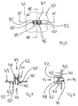
- FIGS. 7 to 9 before plugging a plug 49 designed according to the invention in the on the inside 42 of the panel 40th formed first coupling opening 44 of the coupling 41, the centering bushing 47 inserted into the receptacle 46. Subsequently, the plug 49 is inserted into the first coupling opening 44 and latched to the coupling 41, thereby on the one hand the centering bushing 47 and on the other hand the plug 49 are fixed in the region of the coupling 41.
- the couplings 41 have latching elements 50 which cooperate with latching elements 51 of the plug 49.
- the latching elements 51 of the plug 49 are designed as barb-like anchoring elements, which snap into the formed as openings or recesses locking elements 50 on the inside 42 of the panel 40.
- the latching elements 50 and 51 for fixing the plug 49 and thus the centering bushing 47 on the inner side 42 of the panel 40 are outside a coupling area for the standard plug on the outer side 43 of the panel 40.
- the coupling area for a SC standard plug is defined by latching elements 52 and guides 94.
- the locking elements 50 designed as openings or recesses are accordingly located laterally next to the latching elements 52 and guides 94 for the standard plug.
- FIGS. 10 to 12 show a panel 53 of an optical waveguide distribution device according to the invention, in which couplings 54 engage in openings 55 within a panel 53 are.
- the couplings 54 are in turn formed in one piece and form in the region of an inner side 56 of the panel 53, the first coupling opening 44 and in the region of an outer side 57 of the panel 53, the second coupling opening 45.
- the couplings 54 of the embodiment of Figs. 10 to 12 are correct in their construction and their mode of operation with the clutches 41 of the embodiment of FIG. 1 to 9, so that the same reference numerals are used to avoid unnecessary repetition for the same components.
- the couplings 54 are latched into openings 55 in the panel 53, for which purpose the couplings 54 have latching lugs 58 which, when the couplings 54 are inserted into the openings 55 of the panel 53 barb-like snap into the panel 53.
- recesses 59 are integrated adjacent to the latching lugs 58 into the couplings 54, which allow an elastic deformability of the latching lugs 58 in the sense of the snap-in movement described above.
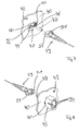
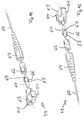
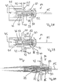
- a first exemplary embodiment of a plug 49 of a prefabricated optical waveguide 60 already shown in FIGS. 7, 8, 9 and 10 will be described below with reference to FIGS. 13 to 18.
- a free end of the optical waveguide 60 is assigned a ferrule 61, wherein in the region of the ferrule 61 the optical waveguide 60 is freed from its protective covering and accordingly stripped.
- the plug 49 in addition to the ferrule 61, which is assigned to the free end of the optical waveguide 60, comprises a ferrule backing 62, a plug housing 63 and a kink protection sleeve 64. It lies within the meaning of the present invention that the ferrule 61 of the optical waveguide 60 is mounted unsprung or springless in the connector housing 63.
- the ferrule 61 is mounted in the plug housing 63 ball-joint-like manner.
- the transverse forces acting on the plug 49 are visualized in FIGS. 16 and 17 by double arrows 65.
- the ball joint-like mounting of the ferrule 61 in the plug housing 63 is realized in that the ferrule 61 has a thickening 66, wherein the thickening 66 forms two karlotten shame surfaces 67.
- the two karlottenartigen surfaces 67 of the thickening 66 of the ferrule 61 cooperate with two complementary curved surfaces, namely with a first complementarily curved surface 68 of the connector housing 63 and a second complementarily curved surface 69 of the Ferrulen accordinglylagers 62.
- a ball joint-like mounting of the ferrule 61 is realized both on the plug housing 63 and the Ferrulen accordinglylager 62 of the plug 49.
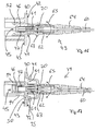
- FIG. 18 shows the plug 49 of FIGS. 13 to 17 in a position inserted into the coupling 41 from the inside 42 of the panel 40, together with a standard plug 71 inserted from the outside 43 of the panel 40 .
- Fig. 18 is a so-called SC connector, in which a ferrule 72 is resiliently mounted via a spring element 73.
- the structure of the standard plug 71 is familiar to the person skilled in the art and therefore needs no further explanation. In the assembly position shown in FIG.
- both ferrules 61 and 72 of the two plugs 49 and 71 are in the centering bushing 47 guided, wherein the spring element 72 of the standard connector 71 presses the ferrule 72 of the standard plug 71 against the ferrule 61 of the plug 49 according to the invention and thus the karlottenförmige surface 67 of the ferrule 61 against the complementarily curved surface 69 of the Ferrulenumblelagers 62.
- the two ferrules 61 and 72 of the two plugs 49 and 61 are exactly aligned with each other, so as to position the guided in the ferrules optical fiber to ensure minimum attenuation to each other exactly.
- a free end of the ferrule 61 projects relative to the latching elements 51 of the plug housing 63. This ensures that the ferrule 61 of the fully assembled connector 49 z. B. can be edited by grinding.
- the panel 40 on the inner side 42 has projections 95 which, together with the latching elements 51 of the plug housing 63, provide the latching connection between the coupling 41 or ensure panel 40 and connector 49.
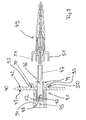
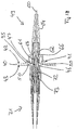
- FIGS. 19 to 24 show a second exemplary embodiment of a plug 47 according to the invention.
- This plug 47 in turn has a ferrule 75 for an optical waveguide 76, the ferrule 75 of the plug of the exemplary embodiment according to FIGS. 19 to 24 being designed as a standard cylindrical ferrule.
- the ferrule 75 of the plug 47 is accommodated in a Ferrulenhalterung 77, wherein the ferrule 75 is mounted on the Ferrulenhalterung 77 in a Ferrulen accordinglylager 78 of the plug 74 without a spring and ball joint. Further assemblies of the plug 74 of the embodiment of FIG.
- FIG. 19 to 24 are again a plug housing 79 and a kink protection sleeve 80, wherein the plug housing 79 and the anti-buckling sleeve 80 of the plug 74 shown in FIG. 19 to 24 the plug housing 63 and the anti-buckling sleeve 64 of the plug 49th correspond to FIG. 13 to 18.
- the ferrule holder 47 has a karlotten shame surface 81 which cooperates with a complementarily curved surface 82 of the Ferrulenumblelagers 78 and provides a ball joint-like mounting of the ferrule 75.
- the plug 74 of the exemplary embodiment according to FIGS. 19 to 24 in contrast to the plug 49 of the exemplary embodiment according to FIGS. 13 to 18, only a karlotten-shaped support is provided in the region of a rear side of the ferrule 75.
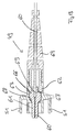
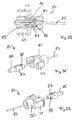
- FIGS. 25 to 30 show a further exemplary embodiment of a plug 84 according to the invention for an optical waveguide 85.
- the optical waveguide 85 is in turn assigned a ferrule 86, which is designed as a standard cylindrical ferrule and accommodates in a ferrule holder 87.
- the ferrule 86 is again springless and ball-joint-like mounted in the plug 84, wherein a karlotten shame surface 88 of the Ferrulenhalterung 87 cooperates with a complementarily curved surface 89 of a plug housing 90 and provides for the ball-joint-like mounting of the ferrule 86.
- FIGS. 28 to 30 show the plug 84 in a position inserted from the inside 42 of the panel 40 into the first coupling opening 44 of a coupling 41. In this position, in turn, the plug 84 fixes the Zentri mecanicsbuchse 47 in the receptacle 46 of the coupling 41st
- the standard plug 71 is inserted from the outside 43 into the second coupling opening 45 of the coupling 41, the spring element 73 of the standard plug 71 pressing the ferrule 72 of the standard plug 71 in the direction of the arrow 91 against the ferrule 86 of the plug 84.
- the karlotten shame surface 88 of the Ferrulenhalterung 87 on the complementarily curved surface 89 of the connector housing 90 to the plant.
- inclinations can be compensated as a result of acting on the plug 84 in the sense of the double arrow 92 transverse forces, since the ferrule 86 in the sense of the double arrow 93 can perform a sideways movement.
- All plugs 49, 47 and 84 according to the invention therefore have a ferrule mounted without a spring as well as a ball joint.
- the connectors differ only in terms of the number of their modules, the connector 84 of the embodiment of FIGS. 25 to 30 has the least number of modules and thus the simplest structural design.
Abstract
Description
Die Erfindung betrifft eine Lichtwellenleiteranschlusseinrichtung gemäß dem Oberbegriff des Anspruchs 1. Des weiteren betrifft die Erfindung einen Stecker für Lichtwellenleiter nach dem Oberbegriff des Anspruchs 11 und eine Steckverbindung für Lichtwellenleiter nach dem Oberbegriff des Anspruchs 19.The invention relates to a fiber optic connection device according to the preamble of claim 1. Furthermore, the invention relates to a plug for optical fibers according to the preamble of claim 11 and a connector for optical fibers according to the preamble of claim 19th
In Verteilerschränken für Lichtwellenleiterkabel kommen Anschlusseinrichtungen und/oder Verteilereinrichtungen zum Einsatz, wie sie zum Beispiel aus dem Produktkatalog "Zubehör für LWL-Kabelnetze, Ausgabe 2, Seiten 226 und 227, Jahr 2002, Corning Cable Systems GmbH & Co. KG" bekannt sind. Die dort gezeigten Lichtwellenleiterverteilereinrichtungen dienen insbesondere der Handhabung von mit Steckern vorkonfektionierten Lichtwellenleitern, wie z.B. Patchcords oder Pigtails, wobei dieselben an einer Vorderseite ein Panel aufweisen, in welches steckertypabhängige Kupplungen eingesetzt werden. Das Panel bildet ein Trägerelement für die Kupplungen und wird auch als Schaltfeld oder Rangierfeld bezeichnet.Junction devices and / or distribution devices are used in distribution cabinets for optical waveguide cables, as are known, for example, from the product catalog "Accessories for Fiber Optic Cable Networks, Issue 2, pages 226 and 227, 2002, Corning Cable Systems GmbH & Co. KG". The optical waveguide distribution devices shown there serve, in particular, for the handling of optical waveguides which have been prefabricated with plugs, such as e.g. Patch cords or pigtails, wherein on a front side they have a panel into which plug-type-dependent couplings are inserted. The panel forms a carrier element for the couplings and is also called a patch panel or patch panel.
Die aus dem Stand der Technik bekannten Kupplungen, die in Öffnungen eines Trägerelements bzw. Panels einer Lichtwellenleiteranschlusseinrichtung bzw. einer Lichtwellenleiterverteilereinrichtung Aufnahme finden, sind mehrteilig ausgeführt, wobei äußere Kupplungshälften der Kupplungen durch Schweißen miteinander verbunden werden. In die äußeren Kupplungshälften der aus dem Stand der Technik bekannten Kupplungen wird vor dem Verschweißen eine Zentrierungsbuchse eingesetzt, die der exakten Ausrichtung von zwei Steckern dient, die in den Kupplungen Aufnahme finden. Die aus dem Stand der Technik bekannten Lichtwellenleiteranschlusseinrichtungen bzw. die Kupplungen derselben verfügen über einen komplexen Aufbau und erfordern einen hohen Montageaufwand. Gleiches gilt für die Stecker, die in den Kupplungen Aufnahme finden.The couplings known from the prior art, which are received in openings in a carrier element or panel of an optical waveguide connection device or an optical waveguide distribution device, are designed in several parts, wherein outer coupling halves of the couplings are connected to one another by welding. In the outer coupling halves of the couplings known from the prior art, a centering bushing is used prior to welding, which serves the exact alignment of two plugs, which find in the couplings recording. The from the state of the art Known optical fiber connection devices or the clutches thereof have a complex structure and require a high installation cost. The same applies to the plug, which can be found in the couplings.
Hiervon ausgehend liegt der vorliegenden Erfindung das Problem zu Grunde, eine neuartige Lichtwellenleiteranschlusseinrichtung, einen neuartigen Stecker für Lichtwellenleiter und eine neuartige Steckverbindung für Lichtwellenleiter zu schaffen.On this basis, the present invention based on the problem of creating a novel optical fiber connection device, a novel plug for optical fibers and a novel connector for optical fibers.
Dieses Problem wird durch eine Lichtwellenleiteranschlusseinrichtung mit den Merkmalen des Anspruchs 1 gelöst. Erfindungsgemäß ist die oder jede Kupplung für die Stecker der Lichtwellenleiter einteilig ausgebildet.This problem is solved by an optical waveguide connection device having the features of claim 1. According to the invention, the or each coupling for the connector of the optical waveguide is integrally formed.
Im Sinne der hier vorliegenden Erfindung wird eine einteilige Kupplung für die Stecker von vorzugsweise vorkonfektionierten Lichtwellenleitern vorgeschlagen, wobei die oder jede Kupplung entweder integraler Bestandteil eines Trägerelements, insbesondere eines Panels, ist oder als separate Baugruppe ausgeführt und in Öffnungen des Trägerelements eingerastet ist. Mit der hier vorliegenden Erfindung kann der Aufbau von Kupplungen und damit von Lichtwellenleiteranschlusseinrichtungen gegenüber dem Stand der Technik deutlich vereinfacht werden. Der Montageaufwand sowie die Fertigungskosten werden hierdurch reduziert.For the purposes of the present invention, a one-piece coupling is proposed for the plug of preferably prefabricated optical waveguides, wherein the or each coupling is either an integral part of a support member, in particular a panel, or designed as a separate assembly and engaged in openings of the support member. With the present invention, the construction of couplings and thus of fiber optic connection devices over the prior art can be significantly simplified. The installation effort and the production costs are thereby reduced.
Vorzugsweise weist die oder jede Kupplung an einer Innenseite des Trägerelements eine erste Kupplungsöffnung zur Aufnahme einer Zentrierungsbuchse und zur Aufnahme eines Steckers auf, wobei die Zentrierungsbuchse in der ersten Kupplungsöffnung durch den Stecker gehalten wird. Die oder jede Kupplung weist weiterhin an der Innenseite des Trägerelements Rastelemente auf, die mit Rastelementen des Steckers zusammenwirken, um die Zentrierungsbuchse und den Stecker in der ersten Kupplungsöffnung zu fixieren.Preferably, the or each coupling has on an inner side of the carrier element a first coupling opening for receiving a centering bushing and for receiving a plug, wherein the centering bushing is held in the first coupling opening by the plug. The or each clutch further comprises on the inside of the support member locking elements which cooperate with locking elements of the plug to fix the Zentrierungsbuchse and the plug in the first coupling opening.
Der erfindungsgemäße Stecker ist im unabhängigen Anspruch 11 definiert. Erfindungsgemäß ist die Ferrule im Steckergehäuse ungefedert gelagert, wobei dieselbe im Steckergehäuse zum Ausgleich von Schrägstellungen in Folge von auf den Stecker einwirkenden Querkräften kugelgelenkartig gelagert ist.The plug according to the invention is defined in independent claim 11. According to the ferrule is mounted unsprung in the connector housing, wherein the same is mounted in the plug housing to compensate for inclinations due to transverse forces acting on the plug ball-joint-like.
Die erfindungsgemäße Steckverbindung für Lichtwellenleiter ist im unabhängigen Anspruch 19 definiert.The connector according to the invention for optical waveguides is defined in the independent claim 19.
Bevorzugte Weiterbildungen der Erfindung ergeben sich aus den Unteransprüchen und der nachfolgenden Beschreibung. Ausführungsbeispiele der Erfindung werden, ohne hierauf beschränkt zu sein, anhand der Zeichnung näher erläutert. In der Zeichnung zeigt:
- Fig. 1
- eine perspektivische Seitenansicht auf eine Innenseite eines Panels einer erfindungsgemäßen Lichtwellenleiterverteilereinrichtung nach einem ersten Ausführungsbeispiel der Erfindung;
- Fig. 2
- einen Ausschnitt aus dem Panel der Fig. 1 im Bereich einer Kupplung in einer Ansicht analog zu Fig. 1 auf die Innenseite desselben;
- Fig. 3
- einen Ausschnitt aus dem Panel der Fig. 1 im Bereich einer Kupplung in einer perspektivischen Seitenansicht auf eine Außenseite desselben;
- Fig. 4:
- eine Vorderansicht auf den Ausschnitt der Fig. 2;
- Fig. 5:
- einen Querschnitt durch den Ausschnitt der Fig. 2 bis 4 entlang der Schnittlinie V-V in Fig. 4;
- Fig. 6:
- einen Querschnitt durch den Ausschnitt der Fig. 2 bis 4 entlang der Schnittlinie VI-VI in Fig. 4;
- Fig. 7:
- den Ausschnitt der Fig. 2 zusammen mit einem Stecker und einer Zentrierungsbuchse in einer perspektivischen Seitenansicht auf die Innenseiteseite des Panels;
- Fig. 8:
- die Anordnung der Fig. 7 in einer perspektivischen Seitenansicht auf die Außenseiteseite des Panels;
- Fig. 9:
- einen Querschnitt durch die Anordnung der Fig. 7 bzw. 8;
- Fig. 10:
- eine perspektivische Seitenansicht auf eine Innenseite eines Panels einer erfindungsgemäßen Lichtwellenleiterverteilereinrichtung nach einem zweiten Ausführungsbeispiel der Erfindung;
- Fig. 11:
- einer perspektivische Seitenansicht einer Kupplung der Anordnung der Fig. 10;
- Fig. 12:
- eine weitere perspektivische Seitenansicht der Kupplung der Fig. 11;
- Fig. 13:
- einen Querschnitt durch einen erfindungsgemäßen Stecker nach einem ersten Ausführungsbeispiel der Erfindung für die erfindungsgemäßen Lichtwellenleiterverteilereinrichtung der Fig. 1 bis 9 oder die Lichtwellenleiterverteilereinrichtung der Fig. 10 bis 12;
- Fig. 14:
- eine erste Explosionsdarstellung des erfindungsgemäßen Steckers der Fig. 13;
- Fig. 15
- eine zweite Explosionsdarstellung des erfindungsgemäßen Steckers der Fig. 13;
- Fig. 16:
- einen Querschnitt durch den Stecker der Fig. 13 bis 15, der von einer Innenseite eines Panels der Fig. 1 bis 9 in eine Kupplung desselben eingesteckt ist;
- Fig. 17:
- einen gegenüber Fig. 16 um 90° gedrehten Querschnitt;
- Fig. 18:
- die Anordnung der Fig. 16 und 17 zusammen mit einem von der Außenseite des Panels in die Kupplung desselben eingesteckten Standartstecker;
- Fig. 19:
- einen Querschnitt durch einen erfindungsgemäßen Stecker nach einem zweiten Ausführungsbeispiel der Erfindung für die erfindungsgemäßen Lichtwellenleiterverteilereinrichtung der Fig. 1 bis 9 oder die Lichtwellenleiterverteilereinrichtung der Fig. 10 bis 12;
- Fig. 20:
- eine erste Explosionsdarstellung des erfindungsgemäßen Steckers der Fig. 19;
- Fig. 21:
- eine zweite Explosionsdarstellung des erfindungsgemäßen Steckers der Fig. 19;
- Fig. 22:
- einen Querschnitt durch den Stecker der Fig. 19 bis 20, der von einer Innenseite des Panels der Fig. 1 bis 9 in eine Kupplung desselben eingesteckt ist;
- Fig. 23:
- einen gegenüber Fig. 16 um 90° gedrehten Querschnitt;
- Fig. 24:
- die Anordnung der Fig. 22 und 23 zusammen mit einem von der Außenseite des Panels in die Kupplung desselben eingesteckten Standartstecker;
- Fig. 25:
- einen Querschnitt durch einen erfindungsgemäßen Stecker nach einem dritten Ausführungsbeispiel der Erfindung für die erfindungsgemäßen Lichtwellenleiterverteilereinrichtung der Fig. 1 bis 9 oder die Lichtwellenleiterverteilereinrichtung der Fig. 10 bis 12;
- Fig. 26:
- eine erste Explosionsdarstellung des erfindungsgemäßen Steckers der Fig. 25;
- Fig. 27:
- eine zweite Explosionsdarstellung des erfindungsgemäßen Steckers der Fig. 25;
- Fig. 28:
- einen Querschnitt durch den Stecker der Fig. 25 bis 26, der von einer Innenseite des Panels der Fig. 1 bis 9 in eine Kupplung desselben eingesteckt ist;
- Fig. 29:
- einen gegenüber Fig. 28 um 90° gedrehten Querschnitt; und
- Fig. 30:
- die Anordnung der Fig. 28 und 29 zusammen mit einem von der Außenseite des Panels in die Kupplung desselben eingesteckten Standartstecker.
- Fig. 1
- a perspective side view of an inner side of a panel of an optical waveguide distribution device according to the invention according to a first embodiment of the invention;
- Fig. 2
- a section of the panel of Figure 1 in the region of a clutch in a view analogous to Figure 1 on the inside thereof ..;
- Fig. 3
- a section of the panel of Figure 1 in the region of a coupling in a perspective side view on an outside thereof.
- 4:
- a front view of the section of Fig. 2;
- Fig. 5:
- a cross-section through the section of Figure 2 to 4 along the section line VV in Fig. 4.
- Fig. 6:
- a cross-section through the section of Figure 2 to 4 along the section line VI-VI in Fig. 4.
- Fig. 7:
- the section of Figure 2 together with a plug and a Zentrierungsbuchse in a perspective side view of the inner side of the panel.
- Fig. 8:
- the arrangement of Figure 7 in a perspective side view on the outer side of the panel.
- Fig. 9:
- a cross-section through the arrangement of Figures 7 and 8;
- Fig. 10:
- a perspective side view of an inside of a panel of an optical waveguide distribution device according to a second embodiment of the invention;
- Fig. 11:
- a side perspective view of a coupling of the arrangement of FIG. 10;
- Fig. 12:
- another perspective side view of the coupling of FIG. 11;
- Fig. 13:
- a cross section through a connector according to the invention according to a first embodiment of the invention for the optical waveguide distribution device according to the invention of Figures 1 to 9 or the optical waveguide distribution device of Figures 10 to 12.
- Fig. 14:
- a first exploded view of the plug according to the invention of FIG. 13;
- Fig. 15
- a second exploded view of the plug according to the invention of FIG. 13;
- Fig. 16:
- a cross-section through the plug of Figures 13 to 15, which is inserted from an inner side of a panel of Figures 1 to 9 in a coupling thereof ..;
- Fig. 17:
- a cross section rotated by 90 ° with respect to FIG. 16;
- Fig. 18:
- the arrangement of Figures 16 and 17 together with a plugged from the outside of the panel in the same coupling standard connector.
- Fig. 19:
- a cross section through a connector according to the invention according to a second embodiment of the invention for the optical waveguide distribution device according to the invention of Figures 1 to 9 or the optical fiber distribution device of Figures 10 to 12.
- Fig. 20:
- a first exploded view of the plug according to the invention of FIG. 19;
- Fig. 21:
- a second exploded view of the plug according to the invention of FIG. 19;
- Fig. 22:
- a cross-section through the plug of Figures 19 to 20, which is inserted from an inner side of the panel of Figures 1 to 9 in a coupling thereof ..;
- Fig. 23:
- a cross section rotated by 90 ° with respect to FIG. 16;
- Fig. 24:
- the arrangement of Figures 22 and 23 together with a plugged from the outside of the panel in the same coupling standard connector.
- Fig. 25:
- a cross section through a connector according to the invention according to a third embodiment of the invention for the optical waveguide distribution device according to the invention of Figures 1 to 9 or the optical waveguide distribution device of Figures 10 to 12.
- Fig. 26:
- a first exploded view of the connector according to the invention of FIG. 25;
- Fig. 27:
- a second exploded view of the connector according to the invention of FIG. 25;
- Fig. 28:
- a cross-section through the plug of Figures 25 to 26, which is inserted from an inner side of the panel of Figures 1 to 9 in a coupling thereof ..;
- Fig. 29:
- a comparison with Figure 28 rotated by 90 ° cross-section; and
- Fig. 30:
- the arrangement of Figs. 28 and 29 together with a plugged from the outside of the panel in the same connector standard plug.
Nachfolgend wird die hier vorliegende Erfindung unter Bezugsnahme auf Fig. 1 bis 30 in größerem Detail beschrieben.Hereinafter, the present invention will be described with reference to Figs. 1 to 30 in more detail.
Fig. 1 zeigt ein Panel 40 einer erfindungsgemäßen Lichtwellenleiterverteilereinrichtung, wobei ein Panel auch als Schaltfeld oder Rangierfeld bezeichnet wird. Das Panel 40 kann zum Beispiel eine Vorderwand einer im Detail nichtdargestellten Lichtwellenleiterverteilereinrichtung bilden. In das Panel 40 der Fig. 1 sind insgesamt sechs Kupplungen 41 integriert. Fig. 2 zeigt einen Ausschnitt aus dem Panel 40 der Fig. 1 im Bereich einer solchen Kupplung 41 und zwar in einer Blickrichtung auf eine Innenseite 42 des Panels 40. Fig. 3 zeigt den Ausschnitt der Fig. 2 in Blickrichtung auf eine Außenseite 43 des Panels 40.Fig. 1 shows a
Die Kupplungen 41 des Panels 40 sind im Sinne der hier vorliegenden Erfindung einteilig ausgebildet. Im Ausführungsbeispiel der Fig. 1 bis 9 sind dieselben des weiteren integraler Bestandteil des Panels 40, die Kupplungen 41 bilden demnach zusammen mit dem Panel 40 eine monolithische Einheit. Die Kupplungen 41 können zusammen mit dem Panel 40 als Spritzgussteil ausgeführt sein.The
In die Kupplungen 41 kann von beiden Seiten, also sowohl von der Innenseite 42 als auch von der Außenseite 43 aus, jeweils ein Stecker eines Lichtwellenleiters bzw. Lichtwellenleiterkabels eingesteckt werden. Die Kupplungen 41 verfügen demnach über zwei Kupplungsöffnungen, nämlich eine erste Kupplungsöffnung 44 an der Innenseite 42 des Panels 40 und eine zweite Kupplungsöffnung 45 an der Außenseite 43 desselben. In die an der Innenseite 42 positionierte erste Kupplungsöffnung 44 kann ein erfindungsgemäß ausgebildeter Stecker, auf den weiter unten in größerem Detail eingegangen wird, eingesteckt werden. Die zweite Kupplungsöffnung 45 im Bereich der Außenseite 43 des Panels dient der Aufnahme eines Standardsteckers, in den gezeigten Ausführungsbeispielen der Aufnahme eines sogenannten SC-Steckers.In the
Die einteiligen Kupplungen 41 des Panels 40 verfügen über eine Aufnahme 46 für eine Zentrierungsbuchse 47. Die Aufnahme 46 ist im Bereich der Innenseite 42 des Panels 40 offen ausgebildet und erlaubt an der Innenseite 42 ein ungehindertes Einführen der Zentrierungsbuchse 47 in die Aufnahme 46. Im Bereich der Außenseite 43 des Panels 40 ist die Aufnahme 46 eingeschnürt und bildet hier einen Anschlag 48 für die Zentrierungsbuchse 47. Wie Fig. 7 bis 9 entnommen werden kann, wird vor dem Einstecken eines erfindungsgemäß ausgebildeten Steckers 49 in die an der Innenseite 42 des Panels 40 ausgebildete erste Kupplungsöffnung 44 der Kupplung 41 die Zentrierungsbuchse 47 in die Aufnahme 46 eingeführt. Anschließend wird der Stecker 49 in die erste Kupplungsöffnung 44 gesteckt und an der Kupplung 41 verrastet, wobei hierdurch einerseits die Zentrierungsbuchse 47 und andererseits der Stecker 49 im Bereich der Kupplung 41 fixiert werden.The one-
Zur Fixierung des Steckers 49 an der Innenseite 42 des Panels 40 im Bereich einer Kupplung 41 verfügen die Kupplungen 41 über Rastelemente 50, die mit Rastelementen 51 des Steckers 49 zusammenwirken. Die Rastelemente 51 des Steckers 49 sind als widerhakenartige Verankerungselemente ausgebildet, die in die als Öffnungen bzw. Ausnehmungen ausgebildeten Rastelemente 50 auf der Innenseite 42 des Panels 40 einschnappen. Wie insbesondere Fig. 5, 6 und 9 entnommen werden kann, liegen die Rastelemente 50 und 51 zur Fixierung des Steckers 49 und damit der Zentrierungsbuchse 47 an der Innenseite 42 des Panels 40 außerhalb eines Kupplungsbereichs für den Standardstecker an der Außenseite 43 des Panels 40. Der Kupplungsbereich für einen SC-Standardstecker wird durch Rastelemente 52 und Führungen 94 definiert. Die als Öffnungen bzw. Ausnehmungen ausgebildeten Rastelemente 50 liegen demnach seitlich neben den Rastelementen 52 und Führungen 94 für den Standardstecker.For fixing the
Wie bereits erwähnt, sind im Ausführungsbeispiel der Fig. 1 bis 9 die Kupplungen 41 integraler Bestandteil des Panels 40. Im Unterschied hierzu zeigen Fig. 10 bis 12 ein Panel 53 einer erfindungsgemäßen Lichtwellenleiterverteilereinrichtung, bei welcher Kupplungen 54 in Öffnungen 55 innerhalb eines Panels 53 eingerastet sind. Die Kupplungen 54 sind wiederum einteilig ausgebildet und bilden im Bereich einer Innenseite 56 des Panels 53 die erste Kupplungsöffnung 44 und im Bereich einer Außenseite 57 des Panels 53 die zweite Kupplungsöffnung 45. Die Kupplungen 54 des Ausführungsbeispiels der Fig. 10 bis 12 stimmen hinsichtlich ihres Aufbaus sowie ihrer Funktionsweise mit den Kupplungen 41 des Ausführungsbeispiels gemäß Fig. 1 bis 9 überein, sodass zur Vermeidung unnötiger Wiederholungen für gleiche Baugruppen gleiche Bezugziffern verwendet werden.As already mentioned, in the exemplary embodiment of FIGS. 1 to 9, the
Der einzige Unterschied besteht wie bereits erwähnt darin, dass im Ausführungsbeispiel der Fig. 10 bis 12 die Kupplungen 54 in Öffnungen 55 innerhalb des Panels 53 eingerastet werden, wobei hierzu die Kupplungen 54 Rastnasen 58 aufweisen, die beim Einführen der Kupplungen 54 in die Öffnungen 55 des Panels 53 widerhakenartig in das Panel 53 einschnappen. Zu Gewährleistung dieser Einschnappbewegung sind benachbart zu den Rastnasen 58 in die Kupplungen 54 Aussparungen 59 integriert, die eine elastische Verformbarkeit der Rastnasen 58 im Sinne der oben beschriebenen Einschnappbewegung ermöglichen.The only difference, as already mentioned, is that in the exemplary embodiment of FIGS. 10 to 12, the
Nachfolgend wird unter Bezugnahme auf Fig. 13 bis 18 ein erstes Ausführungsbeispiel eines bereits in Fig. 7, 8, 9 und 10 gezeigten Steckers 49 eines vorkonfektionierten Lichtwellenleiters 60 beschrieben.A first exemplary embodiment of a
Einem freien Ende des Lichtwellenleiters 60 ist eine Ferrule 61 zugeordnet, wobei im Bereich der Ferrule 61 der Lichtwellenleiter 60 von seiner Schutzhülle befreit und demnach entmantelt ist. Im Ausführungsbeispiel der Fig. 13 bis 18 umfasst der Stecker 49 neben der Ferrule 61, die dem freien Ende des Lichtwellenleiters 60 zugeordnet ist, ein Ferrulengegenlager 62, ein Steckergehäuse 63 und eine Knickschutzhülle 64. Es liegt dabei im Sinne der hier vorliegenden Erfindung, dass die Ferrule 61 des Lichtwellenleiters 60 im Steckergehäuse 63 ungefedert bzw. federlos gelagert ist. Zum Ausgleich von Schrägstellungen infolge von auf den Stecker 49 einwirkenden Querkräften ist die Ferrule 61 im Steckergehäuse 63 kugelgelenkartig gelagert. Die auf den Stecker 49 einwirkenden Querkräfte sind in Fig. 16 und 17 durch Doppelpfeile 65 visualisiert.A free end of the
Im Ausführungsbeispiel der Fig. 13 bis 18 wird die kugelgelenkartige Lagerung der Ferrule 61 im Steckergehäuse 63 dadurch realisiert, dass die Ferrule 61 über eine Aufdickung 66 verfügt, wobei die Aufdickung 66 zwei karlottenartige Flächen 67 bildet. Die beiden karlottenartigen Flächen 67 der Aufdickung 66 der Ferrule 61 wirken mit zwei komplementär gewölbten Flächen zusammen, nämlich mit einer ersten komplementär gewölbten Fläche 68 des Steckergehäuses 63 und einer zweiten komplementär gewölbten Fläche 69 des Ferrulengegenlagers 62. Auf diese Weise wird eine kugelgelenkartige Lagerung der Ferrule 61 sowohl am Steckergehäuse 63 als auch am Ferrulengegenlager 62 des Steckers 49 realisiert. Wirken bei einem in eine Kupplung 41 eingesteckten Stecker 49 auf denselben im Sinne der Doppelpfeile 65 (siehe Fig. 16 und 17) Querkräfte ein, so kann die Ferrule 61 aufgrund der kugelgelenkartigen bzw. karlottenförmigen Lagerung eine leichte Schwenkbewegung ausführen. Dabei entsteht eine durch die Doppelpfeile 70 visualisierte Seitwärtsbewegung der Ferrule 61, die durch das Spiel zwischen der Zentrierungsbuchse 47 und der Aufnahme 46 für die Zentrierungsbuchse 47 ausgeglichen werden kann. Die Zentrierungsbuchse 47 ist, wie insbesondere Fig. 16 entnommen werden kann, in Längsrichtung geschlitzt.In the embodiment of FIGS. 13 to 18, the ball joint-like mounting of the
Fig. 18 zeigt den Stecker 49 der Fig. 13 bis 17 in einer in die Kupplung 41 von der Innenseite 42 des Panels 40 aus eingesteckten Position, zusammen mit einem von der Außenseite 43 des Panels 40 aus eingesteckten Standardstecker 71. Bei dem Standardstecker 71 der Fig. 18 handelt sich es sich um einen sogenannten SC-Stecker, in welchem eine Ferrule 72 über ein Federelement 73 federnd gelagert ist. Der Aufbau des Standardsteckers 71 ist dem hier angesprochenen Fachmann geläufig und bedarf daher keiner näheren Erläuterung. In der in Fig. 18 gezeigten Montageposition, in welcher sowohl der erfindungsgemäße Stecker 49 als auch der Standardstecker 41 in eine Kupplung 41 des Panels 40 einer erfindungsgemäßen Lichtwellenielterverteilereinrichtung eingesteckt sind, sind beide Ferrulen 61 und 72 der beiden Stecker 49 und 71 in der Zentrierungsbuchse 47 geführt, wobei das Federelement 72 des Standardsteckers 71 die Ferrule 72 des Standardsteckers 71 gegen die Ferrule 61 des erfindungsgemäßen Steckers 49 und damit die karlottenförmige Fläche 67 der Ferrule 61 gegen die komplementär gewölbte Fläche 69 des Ferrulengegenlagers 62 drückt. Hierdurch werden die beiden Ferrulen 61 sowie 72 der beiden Stecker 49 und 61 exakt zueinander ausgerichtet, um so die in den Ferrulen geführten Lichtwellenleiter zur Gewährleistung einer minimalen Dämpfung exakt zueinander zu positionieren.FIG. 18 shows the
Wie insbesondere Fig. 13 entnommen werden kann, steht ein freies Ende der Ferrule 61 gegenüber den Rastelementen 51 des Steckergehäuses 63 vor. Hierdurch ist gewährleistet, dass die Ferrule 61 des fertig montierten Steckers 49 z. B. durch Schleifen bearbeitet werden kann. Um dennoch ein wiederhakenartiges Einrasten der Rastelemente 51 des Steckergehäuses 63 in die als Öffnungen ausgebildeten Rastelemente 50 des Panels 40 zu ermöglichen, verfügt das Panel 40 an der Innenseite 42 über Vorsprünge 95, die zusammen mit den Rastelementen 51 des Steckergehäuses 63 die Rastverbindung zwischen Kupplung 41 bzw. Panel 40 und Stecker 49 gewährleisten.As can be seen in particular from FIG. 13, a free end of the
Ein zweites Ausführungsbeispiel eines erfindungsgemäßen Steckers 47 zeigen Fig. 19 bis 24. Dieser Stecker 47 verfügt wiederum über eine Ferrule 75 für einen Lichtwellenleiter 76, wobei die Ferrule 75 des Steckers des Ausführungsbeispiels gemäß Fig. 19 bis 24 als zylindrische Standardferrule ausgebildet ist. Die Ferrule 75 des Steckers 47 ist in einer Ferrulenhalterung 77 aufgenommen, wobei die Ferrule 75 über die Ferrulenhalterung 77 in einem Ferrulengegenlager 78 des Steckers 74 federlos und kugelgelenkartig gelagert ist. Weitere Baugruppen des Steckers 74 des Ausführungsbeispiels gemäß Fig. 19 bis 24 sind wiederum ein Steckergehäuse 79 sowie eine Knickschutzhülle 80, wobei das Steckergehäuse 79 und die Knickschutzhülle 80 des Steckers 74 gemäß Fig. 19 bis 24 dem Steckergehäuse 63 sowie der Knickschutzhülle 64 des Steckers 49 gemäß Fig. 13 bis 18 entsprechen.FIGS. 19 to 24 show a second exemplary embodiment of a
Im Ausführungsbeispiel der Fig. 19 bis 24 verfügt die Ferrulenhalterung 47 über eine karlottenartige Fläche 81, die mit einer komplementär gewölbten Fläche 82 des Ferrulengegenlagers 78 zusammenwirkt und eine kugelgelenkartige Lagerung der Ferrule 75 bereitstellt. Beim Stecker 74 des Ausführungsbeispiels gemäß Fig. 19 bis 24 ist im Unterschied zum Stecker 49 des Ausführungsbeispiels gemäß Fig. 13 bis 18 lediglich eine karlottenförmige Auflage im Bereich einer Rückseite der Ferrule 75 vorhanden. In dem Zustand, in dem der Stecker 74 von der Innenseite 42 her in die erste Kupplungsöffnung 44 der Kupplung 41 des Panels 40 und ein Standardstecker 71 von der Außenseite 43 her in die zweite Kupplungsöffnung 45 eingeschoben ist, drückt im Sinne des Pfeils 83 (siehe Fig. 22 und 23) das Federelement 73 des Standardsteckers 71 die Ferrule 72 des Standardsteckers 71 gegen die Ferrule 75 des erfindungsgemäßen Steckers 74 und damit die Ferrulenhalterung 77 gegen das Ferrulengegenlager 78. Hinsichtlich der übrigen Details und der Funktionsweise des Steckers 74 kann auf die Ausführungen zum Stecker 49 verwiesen werden.In the embodiment of FIGS. 19 to 24, the
Ein weiteres Ausführungsbeispiel eines erfindungsgemäßen Steckers 84 für einen Lichtwellenleiter 85 zeigen Fig. 25 bis 30. Dem Lichtwellenleiter 85 ist wiederum eine Ferrule 86 zugeordnet, die als zylindrische Standardferrule ausgebildet ist und in einer Ferrulenhalterung 87 Aufnahme findet. Die Ferrule 86 ist wiederum im Stecker 84 federlos und kugelgelenkartig gelagert, wobei eine karlottenartige Fläche 88 der Ferrulenhalterung 87 mit einer komplementär gewölbten Fläche 89 eines Steckergehäuses 90 zusammenwirkt und für die kugelgelenkartige Lagerung der Ferrule 86 sorgt.FIGS. 25 to 30 show a further exemplary embodiment of a
Fig. 28 bis 30 zeigen den Stecker 84 in einer von der Innenseite 42 des Panels 40 aus in die erste Kupplungsöffnung 44 einer Kupplung 41 eingesteckten Position. In dieser Position fixiert wiederum der Stecker 84 die Zentrierungsbuchse 47 in der Aufnahme 46 der Kupplung 41.FIGS. 28 to 30 show the
In Fig. 30 ist der Standardstecker 71 von der Außenseite 43 her in die zweite Kupplungsöffnung 45 der Kupplung 41 eingesteckt, wobei das Federelement 73 des Standardsteckers 71 die Ferrule 72 des Standardsteckers 71 im Sinne des Pfeils 91 gegen die Ferrule 86 des Steckers 84 drückt. Hierdurch kommt wiederum die karlottenartige Fläche 88 der Ferrulenhalterung 87 auf der komplementär gewölbten Fläche 89 des Steckergehäuses 90 zur Anlage. Es können wiederum Schrägstellungen in Folge von auf den Stecker 84 im Sinne des Doppelpfeils 92 einwirkenden Querkräften ausgeglichen werden, da die Ferrule 86 im Sinne des Doppelpfeils 93 eine Seitwärtsbewegung ausführen kann.In FIG. 30, the
Alle erfindungsgemäßen Stecker 49, 47 bzw. 84 verfügen demnach über eine federlos sowie kugelgelenkartig gelagerte Ferrule. Die Stecker unterscheiden sich lediglich hinsichtlich der Anzahl ihrer Baugruppen, wobei der Stecker 84 des Ausführungsbeispiels der Fig. 25 bis 30 über die geringste Anzahl von Baugruppen und damit über den einfachsten konstruktiven Aufbau verfügt.All plugs 49, 47 and 84 according to the invention therefore have a ferrule mounted without a spring as well as a ball joint. The connectors differ only in terms of the number of their modules, the
Obwohl die Erfindung unter Bezugnahme auf Fig. 1 bis 30 am Beispiel von Lichtwellenleiterverteilereinrichtung beschrieben wurde, sei darauf hingewiesen, dass die erfindungsgemäße Steckverbindungstechnik auch bei Lichtwellenleiteranschlusseinrichtungen zum Einsatz kommen kann. Als Beispiel einer solchen Lichtwellenleiteranschlusseinrichtungen sei hier eine Anschlussdose genannt.Although the invention has been described with reference to FIGS. 1 to 30 using the example of an optical waveguide distribution device, it should be pointed out that the plug-in connection technology according to the invention can also be used in the case of optical waveguide connection devices. As an example of such a Lichtwellenleiteranschlusseinrichtungen here is called a junction box.
- 4040
- Panelpanel
- 4141
- Kupplungclutch
- 4242
- Innenseiteinside
- 4343
- Außenseiteoutside
- 4444
- erste Kupplungsöffnungfirst coupling opening
- 4545
- zweite Kupplungsöffnungsecond coupling opening
- 4646
- Aufnahmeadmission
- 4747
- ZentrierungsbuchseZentrierungsbuchse
- 4848
- Anschlagattack
- 4949
- Steckerplug
- 5050
- Rastelementlocking element
- 5151
- Rastelementlocking element
- 5252
- Rastelementlocking element
- 5353
- Panelpanel
- 5454
- Kupplungclutch
- 5555
- Öffnungopening
- 5656
- Innenseiteinside
- 5757
- Außenseiteoutside
- 5858
- Rastnaselocking lug
- 5959
- Aussparungrecess
- 6060
- Lichtwellenleiteroptical fiber
- 6161
- Ferruleferrule
- 6262
- FerrulengegenlagerFerrulengegenlager
- 6363
- Steckergehäuseplug housing
- 6464
- KnickschutzhülleWith Boot
- 6565
- Doppelpfeildouble arrow
- 6666
- Aufdickungthickening
- 6767
- Flächearea
- 6868
- Flächearea
- 6969
- Flächearea
- 7070
- Doppelpfeildouble arrow
- 7171
- Standardsteckerstandard plug
- 7272
- Ferruleferrule
- 7373
- Federelementspring element
- 7474
- Steckerplug
- 7575
- Ferruleferrule
- 7676
- Lichtwellenleiteroptical fiber
- 7777
- Ferrulenhalterungferrule holder
- 7878
- FerrulengegenlagerFerrulengegenlager
- 7979
- Steckergehäuseplug housing
- 8080
- KnickschutzhülleWith Boot
- 8181
- Flächearea
- 8282
- Flächearea
- 8383
- Pfeilarrow
- 8484
- Steckerplug
- 8585
- Lichtwellenleiteroptical fiber
- 8686
- Ferruleferrule
- 8787
- Ferrulenhalterungferrule holder
- 8888
- Flächearea
- 8989
- Flächearea
- 9090
- Steckergehäuseplug housing
- 9191
- Pfeilarrow
- 9292
- Doppelpfeildouble arrow
- 9393
- Doppelpfeildouble arrow
- 9494
- Führungguide
- 9595
- Vorsprunghead Start
Claims (21)
Applications Claiming Priority (1)
| Application Number | Priority Date | Filing Date | Title |
|---|---|---|---|
| DE202004020043U DE202004020043U1 (en) | 2004-12-22 | 2004-12-22 | Fiber optic connection device, plug and connector for optical fibers |
Publications (3)
| Publication Number | Publication Date |
|---|---|
| EP1674907A2 true EP1674907A2 (en) | 2006-06-28 |
| EP1674907A3 EP1674907A3 (en) | 2006-08-16 |
| EP1674907B1 EP1674907B1 (en) | 2007-10-24 |
Family
ID=35853892
Family Applications (1)
| Application Number | Title | Priority Date | Filing Date |
|---|---|---|---|
| EP05026679A Not-in-force EP1674907B1 (en) | 2004-12-22 | 2005-12-07 | Plug for optical fibre |
Country Status (5)
| Country | Link |
|---|---|
| US (1) | US20060159401A1 (en) |
| EP (1) | EP1674907B1 (en) |
| AT (1) | ATE376682T1 (en) |
| DE (2) | DE202004020043U1 (en) |
| ES (1) | ES2296054T3 (en) |
Families Citing this family (1)
| Publication number | Priority date | Publication date | Assignee | Title |
|---|---|---|---|---|
| US9507098B2 (en) * | 2012-03-08 | 2016-11-29 | Tyco Electronics Corporation | Multi-fiber connector with ferrule float |
Citations (11)
| Publication number | Priority date | Publication date | Assignee | Title |
|---|---|---|---|---|
| DE8221983U1 (en) * | 1982-08-03 | 1983-06-23 | Spinner-GmbH Elektrotechnische Fabrik, 8000 München | LIGHTWAVE LEAD CONNECTOR |
| US4445753A (en) * | 1980-10-31 | 1984-05-01 | Socapex | End fitting for optical fibre connector and connector equipped with such an end fitting |
| EP0207373A1 (en) * | 1985-06-21 | 1987-01-07 | Siemens Aktiengesellschaft | Ferrule for an optical wave guide |
| EP0443454A2 (en) * | 1990-02-20 | 1991-08-28 | PIRELLI CAVI S.p.A. | Swivelling optical connector for joining optical fibres to discrete optical components and sensor using one or more optical connectors |
| US5276750A (en) * | 1993-04-02 | 1994-01-04 | The Whitaker Corporation | Connectors having translational and rotational compliance about the leading edge |
| EP0928978A1 (en) * | 1997-12-22 | 1999-07-14 | Lucent Technologies Inc. | Connector for plastic optical fiber |
| EP1130433A1 (en) * | 2000-02-29 | 2001-09-05 | Lucent Technologies Inc. | Interconnection system for optical circuit boards |
| EP1258759A2 (en) * | 2001-05-16 | 2002-11-20 | Fci | Fiber optic adapter |
| US20020186931A1 (en) * | 2001-04-20 | 2002-12-12 | Koji Seo | Housing for optical connector and optical connector |
| US20040017982A1 (en) * | 2002-04-16 | 2004-01-29 | Masahiro Nakajima | Optical functioning component |
| WO2004061503A1 (en) * | 2002-10-24 | 2004-07-22 | Molex Incorporated | Fiber optic connector module |
Family Cites Families (8)
| Publication number | Priority date | Publication date | Assignee | Title |
|---|---|---|---|---|
| DE2918024C2 (en) * | 1979-05-04 | 1981-07-30 | Licentia Patent-Verwaltungs-Gmbh, 6000 Frankfurt | Adjustment device for an optical fiber connection with lens coupling |
| JP3212063B2 (en) * | 1995-03-08 | 2001-09-25 | 日本電信電話株式会社 | Optical receptacle |
| JP4014784B2 (en) * | 1999-04-09 | 2007-11-28 | 株式会社精工技研 | Optical connector adapter |
| US6367984B1 (en) * | 1999-11-10 | 2002-04-09 | Lucent Technologies, Inc. | Optical fiber adapter |
| JP2001215358A (en) * | 2000-01-31 | 2001-08-10 | Molex Inc | Optical fiber ferrule and its manufacturing method |
| DE10219935A1 (en) * | 2002-05-03 | 2003-11-27 | Krone Gmbh | Device for an optical fiber connection |
| US6619856B1 (en) * | 2002-05-20 | 2003-09-16 | Fitel Usa Corp. | Polarization maintaining optical fiber connector adapter |
| US7244066B2 (en) * | 2005-02-25 | 2007-07-17 | Corning Cable Systems Llc | Fiber optic receptacle and plug assembly including alignment sleeve insert |
-
2004
- 2004-12-22 DE DE202004020043U patent/DE202004020043U1/en not_active Expired - Lifetime
-
2005
- 2005-12-07 DE DE502005001775T patent/DE502005001775D1/en not_active Expired - Fee Related
- 2005-12-07 AT AT05026679T patent/ATE376682T1/en not_active IP Right Cessation
- 2005-12-07 EP EP05026679A patent/EP1674907B1/en not_active Not-in-force
- 2005-12-07 ES ES05026679T patent/ES2296054T3/en active Active
- 2005-12-22 US US11/316,223 patent/US20060159401A1/en not_active Abandoned
Patent Citations (11)
| Publication number | Priority date | Publication date | Assignee | Title |
|---|---|---|---|---|
| US4445753A (en) * | 1980-10-31 | 1984-05-01 | Socapex | End fitting for optical fibre connector and connector equipped with such an end fitting |
| DE8221983U1 (en) * | 1982-08-03 | 1983-06-23 | Spinner-GmbH Elektrotechnische Fabrik, 8000 München | LIGHTWAVE LEAD CONNECTOR |
| EP0207373A1 (en) * | 1985-06-21 | 1987-01-07 | Siemens Aktiengesellschaft | Ferrule for an optical wave guide |
| EP0443454A2 (en) * | 1990-02-20 | 1991-08-28 | PIRELLI CAVI S.p.A. | Swivelling optical connector for joining optical fibres to discrete optical components and sensor using one or more optical connectors |
| US5276750A (en) * | 1993-04-02 | 1994-01-04 | The Whitaker Corporation | Connectors having translational and rotational compliance about the leading edge |
| EP0928978A1 (en) * | 1997-12-22 | 1999-07-14 | Lucent Technologies Inc. | Connector for plastic optical fiber |
| EP1130433A1 (en) * | 2000-02-29 | 2001-09-05 | Lucent Technologies Inc. | Interconnection system for optical circuit boards |
| US20020186931A1 (en) * | 2001-04-20 | 2002-12-12 | Koji Seo | Housing for optical connector and optical connector |
| EP1258759A2 (en) * | 2001-05-16 | 2002-11-20 | Fci | Fiber optic adapter |
| US20040017982A1 (en) * | 2002-04-16 | 2004-01-29 | Masahiro Nakajima | Optical functioning component |
| WO2004061503A1 (en) * | 2002-10-24 | 2004-07-22 | Molex Incorporated | Fiber optic connector module |
Non-Patent Citations (1)
| Title |
|---|
| PATENT ABSTRACTS OF JAPAN Bd. 2000, Nr. 19, 5. Juni 2001 (2001-06-05) & JP 2001 033658 A (SEIKO INSTRUMENTS INC), 9. Februar 2001 (2001-02-09) * |
Also Published As
| Publication number | Publication date |
|---|---|
| US20060159401A1 (en) | 2006-07-20 |
| DE502005001775D1 (en) | 2007-12-06 |
| ES2296054T3 (en) | 2008-04-16 |
| EP1674907A3 (en) | 2006-08-16 |
| EP1674907B1 (en) | 2007-10-24 |
| DE202004020043U1 (en) | 2006-02-09 |
| ATE376682T1 (en) | 2007-11-15 |
Similar Documents
| Publication | Publication Date | Title |
|---|---|---|
| EP1775612B1 (en) | Optical cable connecting device | |
| EP1254387B1 (en) | Optical connector for simultaneously connecting a plurality of fiber optical cables and adapter for said connector | |
| EP0516930B1 (en) | Apparatus for connecting conductors | |
| DE102013102023C5 (en) | Optical module for modular industrial connectors | |
| DE3103797A1 (en) | FIBER CONNECTOR | |
| EP0762165A2 (en) | Hybrid connector with modular electrical and optical conductor connections | |
| DE3203929A1 (en) | DETACHABLE COUPLING FOR LIGHT GUIDE | |
| DE19728960C1 (en) | Optical multiple connector | |
| DE3517388C2 (en) | ||
| DE19533498A1 (en) | Connector for an optical fiber cable | |
| EP0762164A2 (en) | Fastening device for light guides | |
| EP0312147B1 (en) | Protecting cover which can be mounted on a plug or on the coupling of a connecting assembly for an optical wave guide | |
| EP1680697A1 (en) | Fibre-optical connector, and single and double coupler for receiving one such connector | |
| EP1674907B1 (en) | Plug for optical fibre | |
| DE202016102706U1 (en) | Cable train catching element | |
| DE102021134076B3 (en) | Coupling for blow-in connectors, fiber optic splice cassette, fiber optic splice box, system for connecting fiber optic cables, and method for laying fiber optic cables | |
| DE60127581T2 (en) | Optical ring network, optical connector and hybrid connector | |
| EP3814819B1 (en) | Plug-in element for an optical plug connector | |
| EP0847541B1 (en) | Optical plug connector | |
| DE202021106964U1 (en) | Coupling for blow-in connector | |
| DE10360105A1 (en) | Connection module for telecommunication and data technology | |
| DE19507659C1 (en) | Optical multiway plug connector for termination and coupling of optical cable | |
| EP2876475B1 (en) | Kit of parts for producing a fibre optic cable connection device | |
| DE19651261B4 (en) | Optical plug | |
| DE19851867A1 (en) | Releasable inter-connection device for optical waveguides |
Legal Events
| Date | Code | Title | Description |
|---|---|---|---|
| PUAI | Public reference made under article 153(3) epc to a published international application that has entered the european phase |
Free format text: ORIGINAL CODE: 0009012 |
|
| AK | Designated contracting states |
Kind code of ref document: A2 Designated state(s): AT BE BG CH CY CZ DE DK EE ES FI FR GB GR HU IE IS IT LI LT LU LV MC NL PL PT RO SE SI SK TR |
|
| AX | Request for extension of the european patent |
Extension state: AL BA HR MK YU |
|
| PUAL | Search report despatched |
Free format text: ORIGINAL CODE: 0009013 |
|
| RTI1 | Title (correction) |
Free format text: FIBRE OPTIC CABLE CONNECTION DEVICE, PLUG AND PLUG CONNECTOR FOR OPTICAL FIBRE |
|
| AK | Designated contracting states |
Kind code of ref document: A3 Designated state(s): AT BE BG CH CY CZ DE DK EE ES FI FR GB GR HU IE IS IT LI LT LU LV MC NL PL PT RO SE SI SK TR |
|
| AX | Request for extension of the european patent |
Extension state: AL BA HR MK YU |
|
| 17P | Request for examination filed |
Effective date: 20060804 |
|
| 17Q | First examination report despatched |
Effective date: 20070212 |
|
| AKX | Designation fees paid |
Designated state(s): AT BE BG CH CY CZ DE DK EE ES FI FR GB GR HU IE IS IT LI LT LU LV MC NL PL PT RO SE SI SK TR |
|
| GRAP | Despatch of communication of intention to grant a patent |
Free format text: ORIGINAL CODE: EPIDOSNIGR1 |
|
| RTI1 | Title (correction) |
Free format text: PLUG FOR OPTICAL FIBRE |
|
| GRAS | Grant fee paid |
Free format text: ORIGINAL CODE: EPIDOSNIGR3 |
|
| GRAA | (expected) grant |
Free format text: ORIGINAL CODE: 0009210 |
|
| AK | Designated contracting states |
Kind code of ref document: B1 Designated state(s): AT BE BG CH CY CZ DE DK EE ES FI FR GB GR HU IE IS IT LI LT LU LV MC NL PL PT RO SE SI SK TR |
|
| REG | Reference to a national code |
Ref country code: GB Ref legal event code: FG4D Free format text: NOT ENGLISH |
|
| REG | Reference to a national code |
Ref country code: CH Ref legal event code: EP |
|
| REG | Reference to a national code |
Ref country code: IE Ref legal event code: FG4D Free format text: LANGUAGE OF EP DOCUMENT: GERMAN |
|
| REF | Corresponds to: |
Ref document number: 502005001775 Country of ref document: DE Date of ref document: 20071206 Kind code of ref document: P |
|
| PGFP | Annual fee paid to national office [announced via postgrant information from national office to epo] |
Ref country code: ES Payment date: 20071226 Year of fee payment: 3 |
|
| GBT | Gb: translation of ep patent filed (gb section 77(6)(a)/1977) |
Effective date: 20080116 |
|
| NLV1 | Nl: lapsed or annulled due to failure to fulfill the requirements of art. 29p and 29m of the patents act | ||
| REG | Reference to a national code |
Ref country code: ES Ref legal event code: FG2A Ref document number: 2296054 Country of ref document: ES Kind code of ref document: T3 |
|
| PG25 | Lapsed in a contracting state [announced via postgrant information from national office to epo] |
Ref country code: SE Free format text: LAPSE BECAUSE OF FAILURE TO SUBMIT A TRANSLATION OF THE DESCRIPTION OR TO PAY THE FEE WITHIN THE PRESCRIBED TIME-LIMIT Effective date: 20080124 Ref country code: NL Free format text: LAPSE BECAUSE OF FAILURE TO SUBMIT A TRANSLATION OF THE DESCRIPTION OR TO PAY THE FEE WITHIN THE PRESCRIBED TIME-LIMIT Effective date: 20071024 |
|
| PG25 | Lapsed in a contracting state [announced via postgrant information from national office to epo] |
Ref country code: PT Free format text: LAPSE BECAUSE OF FAILURE TO SUBMIT A TRANSLATION OF THE DESCRIPTION OR TO PAY THE FEE WITHIN THE PRESCRIBED TIME-LIMIT Effective date: 20080324 Ref country code: LT Free format text: LAPSE BECAUSE OF FAILURE TO SUBMIT A TRANSLATION OF THE DESCRIPTION OR TO PAY THE FEE WITHIN THE PRESCRIBED TIME-LIMIT Effective date: 20071024 Ref country code: BG Free format text: LAPSE BECAUSE OF FAILURE TO SUBMIT A TRANSLATION OF THE DESCRIPTION OR TO PAY THE FEE WITHIN THE PRESCRIBED TIME-LIMIT Effective date: 20080124 Ref country code: IS Free format text: LAPSE BECAUSE OF FAILURE TO SUBMIT A TRANSLATION OF THE DESCRIPTION OR TO PAY THE FEE WITHIN THE PRESCRIBED TIME-LIMIT Effective date: 20080224 Ref country code: LV Free format text: LAPSE BECAUSE OF FAILURE TO SUBMIT A TRANSLATION OF THE DESCRIPTION OR TO PAY THE FEE WITHIN THE PRESCRIBED TIME-LIMIT Effective date: 20071024 Ref country code: SI Free format text: LAPSE BECAUSE OF FAILURE TO SUBMIT A TRANSLATION OF THE DESCRIPTION OR TO PAY THE FEE WITHIN THE PRESCRIBED TIME-LIMIT Effective date: 20071024 Ref country code: PL Free format text: LAPSE BECAUSE OF FAILURE TO SUBMIT A TRANSLATION OF THE DESCRIPTION OR TO PAY THE FEE WITHIN THE PRESCRIBED TIME-LIMIT Effective date: 20071024 |
|
| PGFP | Annual fee paid to national office [announced via postgrant information from national office to epo] |
Ref country code: DE Payment date: 20080131 Year of fee payment: 3 |
|
| REG | Reference to a national code |
Ref country code: IE Ref legal event code: FD4D |
|
| BERE | Be: lapsed |
Owner name: CCS TECHNOLOGY, INC. Effective date: 20071231 |
|
| ET | Fr: translation filed | ||
| PG25 | Lapsed in a contracting state [announced via postgrant information from national office to epo] |
Ref country code: DK Free format text: LAPSE BECAUSE OF FAILURE TO SUBMIT A TRANSLATION OF THE DESCRIPTION OR TO PAY THE FEE WITHIN THE PRESCRIBED TIME-LIMIT Effective date: 20071024 Ref country code: CZ Free format text: LAPSE BECAUSE OF FAILURE TO SUBMIT A TRANSLATION OF THE DESCRIPTION OR TO PAY THE FEE WITHIN THE PRESCRIBED TIME-LIMIT Effective date: 20071024 Ref country code: MC Free format text: LAPSE BECAUSE OF NON-PAYMENT OF DUE FEES Effective date: 20071231 |
|
| PGFP | Annual fee paid to national office [announced via postgrant information from national office to epo] |
Ref country code: FR Payment date: 20071217 Year of fee payment: 3 |
|
| PG25 | Lapsed in a contracting state [announced via postgrant information from national office to epo] |
Ref country code: RO Free format text: LAPSE BECAUSE OF FAILURE TO SUBMIT A TRANSLATION OF THE DESCRIPTION OR TO PAY THE FEE WITHIN THE PRESCRIBED TIME-LIMIT Effective date: 20071024 Ref country code: SK Free format text: LAPSE BECAUSE OF FAILURE TO SUBMIT A TRANSLATION OF THE DESCRIPTION OR TO PAY THE FEE WITHIN THE PRESCRIBED TIME-LIMIT Effective date: 20071024 |
|
| PLBE | No opposition filed within time limit |
Free format text: ORIGINAL CODE: 0009261 |
|
| STAA | Information on the status of an ep patent application or granted ep patent |
Free format text: STATUS: NO OPPOSITION FILED WITHIN TIME LIMIT |
|
| PG25 | Lapsed in a contracting state [announced via postgrant information from national office to epo] |
Ref country code: BE Free format text: LAPSE BECAUSE OF NON-PAYMENT OF DUE FEES Effective date: 20071231 |
|
| 26N | No opposition filed |
Effective date: 20080725 |
|
| PG25 | Lapsed in a contracting state [announced via postgrant information from national office to epo] |
Ref country code: IE Free format text: LAPSE BECAUSE OF FAILURE TO SUBMIT A TRANSLATION OF THE DESCRIPTION OR TO PAY THE FEE WITHIN THE PRESCRIBED TIME-LIMIT Effective date: 20071024 |
|
| PG25 | Lapsed in a contracting state [announced via postgrant information from national office to epo] |
Ref country code: GR Free format text: LAPSE BECAUSE OF FAILURE TO SUBMIT A TRANSLATION OF THE DESCRIPTION OR TO PAY THE FEE WITHIN THE PRESCRIBED TIME-LIMIT Effective date: 20080125 Ref country code: EE Free format text: LAPSE BECAUSE OF FAILURE TO SUBMIT A TRANSLATION OF THE DESCRIPTION OR TO PAY THE FEE WITHIN THE PRESCRIBED TIME-LIMIT Effective date: 20071024 |
|
| PG25 | Lapsed in a contracting state [announced via postgrant information from national office to epo] |
Ref country code: FI Free format text: LAPSE BECAUSE OF FAILURE TO SUBMIT A TRANSLATION OF THE DESCRIPTION OR TO PAY THE FEE WITHIN THE PRESCRIBED TIME-LIMIT Effective date: 20071024 |
|
| PG25 | Lapsed in a contracting state [announced via postgrant information from national office to epo] |
Ref country code: AT Free format text: LAPSE BECAUSE OF NON-PAYMENT OF DUE FEES Effective date: 20071207 |
|
| PG25 | Lapsed in a contracting state [announced via postgrant information from national office to epo] |
Ref country code: CY Free format text: LAPSE BECAUSE OF FAILURE TO SUBMIT A TRANSLATION OF THE DESCRIPTION OR TO PAY THE FEE WITHIN THE PRESCRIBED TIME-LIMIT Effective date: 20071024 |
|
| PG25 | Lapsed in a contracting state [announced via postgrant information from national office to epo] |
Ref country code: LU Free format text: LAPSE BECAUSE OF NON-PAYMENT OF DUE FEES Effective date: 20071207 |
|
| PG25 | Lapsed in a contracting state [announced via postgrant information from national office to epo] |
Ref country code: TR Free format text: LAPSE BECAUSE OF FAILURE TO SUBMIT A TRANSLATION OF THE DESCRIPTION OR TO PAY THE FEE WITHIN THE PRESCRIBED TIME-LIMIT Effective date: 20071024 Ref country code: HU Free format text: LAPSE BECAUSE OF FAILURE TO SUBMIT A TRANSLATION OF THE DESCRIPTION OR TO PAY THE FEE WITHIN THE PRESCRIBED TIME-LIMIT Effective date: 20080425 |
|
| REG | Reference to a national code |
Ref country code: FR Ref legal event code: ST Effective date: 20090831 |
|
| PG25 | Lapsed in a contracting state [announced via postgrant information from national office to epo] |
Ref country code: DE Free format text: LAPSE BECAUSE OF NON-PAYMENT OF DUE FEES Effective date: 20090701 |
|
| REG | Reference to a national code |
Ref country code: ES Ref legal event code: FD2A Effective date: 20081209 |
|
| PG25 | Lapsed in a contracting state [announced via postgrant information from national office to epo] |
Ref country code: ES Free format text: LAPSE BECAUSE OF NON-PAYMENT OF DUE FEES Effective date: 20081209 Ref country code: FR Free format text: LAPSE BECAUSE OF NON-PAYMENT OF DUE FEES Effective date: 20081231 |
|
| REG | Reference to a national code |
Ref country code: CH Ref legal event code: PL |
|
| GBPC | Gb: european patent ceased through non-payment of renewal fee |
Effective date: 20091207 |
|
| PG25 | Lapsed in a contracting state [announced via postgrant information from national office to epo] |
Ref country code: CH Free format text: LAPSE BECAUSE OF NON-PAYMENT OF DUE FEES Effective date: 20091231 Ref country code: LI Free format text: LAPSE BECAUSE OF NON-PAYMENT OF DUE FEES Effective date: 20091231 |
|
| PG25 | Lapsed in a contracting state [announced via postgrant information from national office to epo] |
Ref country code: GB Free format text: LAPSE BECAUSE OF NON-PAYMENT OF DUE FEES Effective date: 20091207 |
|
| PG25 | Lapsed in a contracting state [announced via postgrant information from national office to epo] |
Ref country code: IT Free format text: LAPSE BECAUSE OF NON-PAYMENT OF DUE FEES Effective date: 20071231 |