EP0762164A2 - Fastening device for light guides - Google Patents
Fastening device for light guides Download PDFInfo
- Publication number
- EP0762164A2 EP0762164A2 EP96114338A EP96114338A EP0762164A2 EP 0762164 A2 EP0762164 A2 EP 0762164A2 EP 96114338 A EP96114338 A EP 96114338A EP 96114338 A EP96114338 A EP 96114338A EP 0762164 A2 EP0762164 A2 EP 0762164A2
- Authority
- EP
- European Patent Office
- Prior art keywords
- fastening device
- base body
- clamping
- plug
- holding plate
- Prior art date
- Legal status (The legal status is an assumption and is not a legal conclusion. Google has not performed a legal analysis and makes no representation as to the accuracy of the status listed.)
- Withdrawn
Links
Images

Classifications
-
- G—PHYSICS
- G02—OPTICS
- G02B—OPTICAL ELEMENTS, SYSTEMS OR APPARATUS
- G02B6/00—Light guides; Structural details of arrangements comprising light guides and other optical elements, e.g. couplings
- G02B6/24—Coupling light guides
- G02B6/36—Mechanical coupling means
- G02B6/38—Mechanical coupling means having fibre to fibre mating means
- G02B6/3807—Dismountable connectors, i.e. comprising plugs
- G02B6/3833—Details of mounting fibres in ferrules; Assembly methods; Manufacture
- G02B6/3855—Details of mounting fibres in ferrules; Assembly methods; Manufacture characterised by the method of anchoring or fixing the fibre within the ferrule
-
- G—PHYSICS
- G02—OPTICS
- G02B—OPTICAL ELEMENTS, SYSTEMS OR APPARATUS
- G02B6/00—Light guides; Structural details of arrangements comprising light guides and other optical elements, e.g. couplings
- G02B6/24—Coupling light guides
- G02B6/36—Mechanical coupling means
- G02B6/38—Mechanical coupling means having fibre to fibre mating means
- G02B6/3807—Dismountable connectors, i.e. comprising plugs
- G02B6/3873—Connectors using guide surfaces for aligning ferrule ends, e.g. tubes, sleeves, V-grooves, rods, pins, balls
- G02B6/3874—Connectors using guide surfaces for aligning ferrule ends, e.g. tubes, sleeves, V-grooves, rods, pins, balls using tubes, sleeves to align ferrules
- G02B6/3878—Connectors using guide surfaces for aligning ferrule ends, e.g. tubes, sleeves, V-grooves, rods, pins, balls using tubes, sleeves to align ferrules comprising a plurality of ferrules, branching and break-out means
-
- G—PHYSICS
- G02—OPTICS
- G02B—OPTICAL ELEMENTS, SYSTEMS OR APPARATUS
- G02B6/00—Light guides; Structural details of arrangements comprising light guides and other optical elements, e.g. couplings
- G02B6/24—Coupling light guides
- G02B6/36—Mechanical coupling means
- G02B6/38—Mechanical coupling means having fibre to fibre mating means
- G02B6/3807—Dismountable connectors, i.e. comprising plugs
- G02B6/3887—Anchoring optical cables to connector housings, e.g. strain relief features
- G02B6/3888—Protection from over-extension or over-compression
Definitions
- the invention relates to a fastening device for optical fibers.
- EP 0 503 614 A1 already discloses a strain relief device, in particular for glass fiber cables, which comprises a web part which has a plurality of slots which widen upwards and which serve for the clamping, strain-relieving reception of the cable.
- This device is intended in particular for use at an assembly location where cable ends are only to be temporarily secured and secured and released again.
- Permanent attachment of light guides in an optical connector is known for example from EP 0 484 996 A1.
- a plug part with a wedge piece tapering to a point in the plug-in direction which pushes when plugged between two light guides ending in the other plug part and, in the plugged state, presses them in a clamping manner against walls of this plug part.
- An optical connector is also known from US Pat. No.
- the present invention has for its object to provide an attachment of optical fibers (simplex and duplex lines) that ensures a particularly high level of security and durability even with relatively high pull-out forces.
- the attachment should be easy to assemble and assemble and be integrated into a modular connector.
- FIG. 1 shows an essentially cuboid base body 4 that can be produced by plastic injection molding.
- the two bores 7 and 8 can be seen, into which the single-mode fibers 1 are introduced individually and pushed forward until they stop in the end region 14. Both glass and less expensive plastic optical fibers can be used.
- Duplex cables are separated into two "single conductors" before being inserted. Before the basic body is equipped with one or two fibers 1, the stripping of the fibers is removed to a certain length using a stripping tool.
- the optical waveguides 1 are secured by two holding components acting independently of one another. These two components of the fiber attachment are once by a positive connection by means of Holding plate 5 and on the other hand by a frictional connection, which is caused by the slotted base body 4 and clamping means 2 in the rear area, have been realized.
- the clamping means can, in particular, as shown, be designed as clamping plates 2 which can be pushed onto wedge-shaped contact surfaces 11 arranged on the side surfaces of the base body 4. As can be seen, the inside of the clamping plates 2 have also been designed with a correspondingly inverted wedge shape.
- the holding plate 5, which can be inserted transversely from above into the base body 4, can, for example, as shown, have two U-shaped clamping slots 12 which are open in the insertion direction. In contrast to one of the known insulation displacement connections, however, there is no cutting through of the insulation, but this is only pressed into the clamping slots 12 or is only clamped.
- the holding plate 5 could also be pre-locked in the base body 4, so that no additional handling of an individual part is required.
- a loosening of the holding plate 5 is prevented by the latching hook 6, cf. also Figure 2.
- recesses in the holding plate 5 and corresponding locking means in the base body 4 can be provided.
- the frictional engagement is maintained by the locking hook 3.
- the fastening device according to the invention can easily be modified so that a deliberate subsequent loosening of the two holding components is possible.
- the holding plate 5 can be provided in the region of its upper edge with an attachment which is suitable for pulling out again if means are provided at the same time, for example in order to push the latching hooks 6 sufficiently back before pulling out.
- the fastening device described is particularly suitable for being integrated into at least one of two plug housings which can be joined together.
- a particularly advantageous application is a connector which comprises electrical and optical waveguide plug connections and in which the fastening device according to the invention serves as a light guide module which can be inserted into a socket connector housing by means of guide grooves 16, socket modules also being insertable into the socket connector housing, and the outer dimensions of the modules all being one have the same pitch.
- Such a connector is described in the German patent application filed on the same day with the file number No. ., which is hereby incorporated into the disclosure.
- a light guide counter module which is integrated in the trough bottom of the pin connector housing of the hybrid connector and has centering holes on its top side, into which the centering sleeves 15 of a fastening device accommodated in the socket connector housing can engage when the connector housings are plugged together.
Abstract
Description
Die Erfindung betrifft eine Befestigungsvorrichtung für Lichtwellenleiter.The invention relates to a fastening device for optical fibers.
Die Befestigung und Zugentlastung von Signal- Übertragungskabeln ist ein in immer neuen technischen Zusammenhängen auftretendes Problem. Hinsichtlich der Befestigung von Glas- oder Kunststoffaserkabeln stellen sich insofern besondere Probleme, als bei System-Komponenten für die Lichtwellenleiter-Technik ganz allgemein Genauigkeitsanforderungen im Mikrometerbereich für viele Einzelteile und für das Justieren einzelner Elemente zueinander einzuhalten sind.The attachment and strain relief of signal transmission cables is a problem that arises in ever new technical contexts. With regard to the fastening of glass or plastic fiber cables, there are particular problems insofar as system components for optical fiber technology generally have to meet accuracy requirements in the micrometer range for many individual parts and for the adjustment of individual elements to one another.
Aus der EP 0 503 614 A1 ist bereits eine Zugentlastungsvorrichtung insbesondere für Glasfaserkabel bekannt, die einen Stegteil umfaßt, welcher eine Mehrzahl von sich nach oben hin erweiternden Schlitzen aufweist, die zur klemmenden, zugentlastenden Aufnahme des Kabels dienen. Diese Vorrichtung ist insbesondere für den Einsatz an einem Montageort vorgesehen, an dem Kabelenden nur zeitweise befestigt und gesichert und wieder gelöst werden sollen. Eine dauerhafte Befestigung von Lichtleitern in einem optischen Steckverbinder ist beispielsweise aus der EP 0 484 996 A1 bekannt. Dort ist ein Steckerteil mit einem in Steckrichtung spitz zulaufendem Keilstück beschrieben, das sich beim Stecken zwischen zwei im anderen Steckerteil endenden Lichtleiter schiebt und diese im Steckzustand klemmend gegen Wände dieses Steckerteiles drückt. Aus der US 4,167,303 ist außerdem ein optischer Steckverbinder bekannt, bei dem ein Steckergehäuse Bohrungen aufweist, die einzelne Lichtwellenleiterkabel aufnehmen. Die eigentliche Befestigung geschieht dort mittels über die Lichtleiterenden geschobenen Hülsen und jeweils einem über jede Hülse geschobenen Crimpring, der die als Zwinge dienende Hülse jeweils radial zusammendrückt.EP 0 503 614 A1 already discloses a strain relief device, in particular for glass fiber cables, which comprises a web part which has a plurality of slots which widen upwards and which serve for the clamping, strain-relieving reception of the cable. This device is intended in particular for use at an assembly location where cable ends are only to be temporarily secured and secured and released again. Permanent attachment of light guides in an optical connector is known for example from EP 0 484 996 A1. There is described a plug part with a wedge piece tapering to a point in the plug-in direction, which pushes when plugged between two light guides ending in the other plug part and, in the plugged state, presses them in a clamping manner against walls of this plug part. An optical connector is also known from US Pat. No. 4,167,303, in which a connector housing has bores which accommodate individual optical waveguide cables. The actual attachment takes place there by means of sleeves pushed over the light guide ends and in each case a crimp ring pushed over each sleeve, which radially compresses the sleeve serving as a ferrule.
Diese bestehenden Lösungen sind für manche Anwendungen, in denen eine nahezu 100%-ige Sicherheit und Beständigkeit der Befestigung gefordert wird, noch nicht zufriedenstellend. Dies liegt vor allem daran, daß häufig Kunststoffteile verwendet werden, deren Fertigung mit Toleranzen behaftet ist und deren Material im Laufe der Zeit arbeitet. Die bekannten Befestigungsvorrichtungen sind außerdem nicht für den Einsatz in modularen Stecksystemen geeignet.These existing solutions are not yet satisfactory for some applications in which almost 100% security and durability of the fastening are required. This is mainly due to the fact that plastic parts are often used, the manufacture of which is subject to tolerances and the material of which works over time. The known fastening devices are also not suitable for use in modular plug-in systems.
Der vorliegenden Erfindung liegt die Aufgabe zugrunde, eine Befestigung von Lichtwellenleitern (Simplex- und Duplex-Leitungen) zu schaffen, die auch bei relativ hohen Auszugskräften eine besonders hohe Sicherheit und Dauerhaftigkeit gewährleistet. Darüberhinaus soll die Befestigung leicht montierbar und konfektionierbar und in einen modular aufgebauten Steckverbinder integrierbar sein.The present invention has for its object to provide an attachment of optical fibers (simplex and duplex lines) that ensures a particularly high level of security and durability even with relatively high pull-out forces. In addition, the attachment should be easy to assemble and assemble and be integrated into a modular connector.
Diese Aufgabe wird gelöst durch eine Befestigungsvorrichtung für Lichtwellenleiter
- mit einem im wesentlichen quaderförmigen Grundkörper aus Kunststoffmaterial,
- der zwei getrennte, in Längsrichtung von Stirnfläche zu Stirnfläche verlaufende Bohrungen aufweist, in die jeweils eine Ein-Moden-Faser einschiebbar ist,
- und der wenigstens über einen Teil seiner Länge von den Bohrungen in Querrichtung bis zur jeweiligen Längsseite des Quaders hin geschlitzt ist,
- mit Klemmitteln, durch die die Schlitze so zusammendrückbar sind, daß die Fasern jeweils durch einen Reibschluß klemmend gehalten sind,
- und mit einer parallel zu den Stirnwänden in den Grundkörper einschiebbaren Halteplatte, durch die die Fasern zusätzlich jeweils durch einen Formschluß klemmend gehalten sind.
- with an essentially cuboid base body made of plastic material,
- which has two separate bores running in the longitudinal direction from end face to end face, into each of which a single-mode fiber can be inserted,
- and which is slotted at least over part of its length from the bores in the transverse direction to the respective long side of the cuboid,
- with clamping means by means of which the slots can be pressed together in such a way that the fibers are each held in a clamping manner by a frictional engagement,
- and with a holding plate which can be pushed into the base body parallel to the end walls and by means of which the fibers are each additionally clamped by a positive fit.
Vorteilhafte Ausgestaltungen des Gegenstandes des Anspruchs 1 sind in den Unteransprüchen angegeben.Advantageous embodiments of the subject matter of
Die Erfindung wird anhand eines in den Figuren der Zeichnung dargestellten Ausführungsbeispiels im folgenden näher beschrieben. Es zeigen:
Figur 1 eine erfindungsgemäße Befestigungsvorrichtung in Explosionsdarstellung,Figur 2 einen Querschnitt durch eine Befestigungsvorrichtung gemäßFigur 1, jedoch im montierten Zustand,- Figur 3 einen Längsschnitt durch die Befestigungsvorrichtung gemäß
Figur 2.
- FIG. 1 shows a fastening device according to the invention in an exploded view,
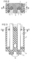
- FIG. 2 shows a cross section through a fastening device according to FIG. 1, but in the assembled state,
- FIG. 3 shows a longitudinal section through the fastening device according to FIG. 2.
In Figur 1 ist ein durch Kunststoffspritzverfahren herstellbarer, im wesentlichen quaderförmiger Grundkörper 4 dargestellt. Erkennbar sind die beiden Bohrungen 7 und 8, in die die Ein-Moden-Fasern 1 einzeln eingeführt und bis zur einem Anschlag im Stirnbereich 14 vorgeschoben werden. Es können sowohl Glas- wie die weniger aufwendigen Kunststoff-Lichtwellenleiter verwendet werden. Duplex-Leitungen werden vor dem Einschieben in zwei "Einzelleiter" aufgetrennt. Bevor der Grundkörper hier mit ein oder zwei Fasern 1 bestückt wird, wird mit einem Abisolierwerkzeug der Mantel der Fasern auf einer bestimmten Länge entfernt.FIG. 1 shows an essentially
Wie insbesondere aus Figur 1 hervorgeht, werden die Lichtwellenleiter 1 durch zwei unabhängig voneinander wirkende Haltekomponenten gesichert. Diese beiden Komponenten der Faserbefestigung sind einmal durch einen Formschluß mittels der Halteplatte 5 und andererseits durch einen Reibschluß, der durch den im hinteren Bereich geschlitzten Grundkörper 4 und Klemmittel 2 bewirkt ist, realisiert worden. Die Klemmittel können insbesondere, wie dargestellt, als Klemmplatten 2 ausgebildet sein, die auf keilförmige, an den Seitenflächen des Grundkörper 4 angeordnete Auflaufflächen 11 aufschiebbar sind. Wie erkennbar, sind auch die Innenseiten der Klemmplatten 2 mit einer entsprechend umgekehrten Keilform ausgestaltet worden. Die quer von oben in den Grundkörper 4 einschiebbare Halteplatte 5 kann beispielsweise, wie dargestellt, zwei in Einschiebrichtung offene, U-förmige Klemmschlitze 12 aufweisen. Es kommt allerdings anders als bei einer der bekannten Schneid-Klemm-Verbindungen nicht zu einem Durchschneiden der Isolation, sondern diese wird in den Kelmmschlitzen 12 nur eingedrückt, bzw. nur eingeklemmt. Die Halteplatte 5 könnte im Grundkörper 4 auch vorverrastet sein, so daß kein zusätzliches Handling eines Einzelteils erforderlich ist.As can be seen in particular from FIG. 1, the
Ein Lösen der Halteplatte 5 wird durch die Rasthaken 6 verhindert, vgl. auch Figur 2. Ebenso können Ausnehmungen in der Halteplatte 5 und entsprechende Rastmittel im Grundkörper 4 vorgesehen sein. Der Reibschluß wird durch die Rasthaken 3 aufrecht erhalten. Die erfindungsgemäße Befestigungsvorrichtung kann ohne weiteres so modifiziert werden, daß ein bewußtes nachträgliches Lösen der beiden Haltekomponenten möglich ist. Beispielsweise kann die Halteplatte 5 im Bereich ihrer Oberkante mit einem Ansatz versehen werden, der zum Wiederherausziehen geeignet ist, wenn gleichzeitig Mittel vorgesehen werden, um beispielsweise die Rasthaken 6 vor dem Herausziehen ausreichend zurückzudrücken.A loosening of the
In Figur 3 ist erkennbar, daß die Faserenden 13 in einem Stirnbereich 14 des Grundkörpers 4 angeschlagen sind und daß in Verlängerung jeder Bohrung 7 und 8 axial aus diesem Stirnbereich 14 herausstehende Zentrierhülsen 15 vorgesehen sind. Nach dem Konfektionieren der Lichtwellenleiter in der Befestigungsvorrichtung, also nach dem Einrasten der Klemmplatten 2 und nachdem die Halteplatte 5 bündig eingedrückt ist, kann die Befestigungsvorrichtung auf einem dafür vorgesehenen an sich bekannten Reiter gelegt und gegen eine beheizbare Platte gedrückt werden, wodurch sogenannte "warmgepreßte" Stirnflächen der Faserenden 13 entstehen. Ein einfaches Abschneiden der Faserenden 13 ist aber auch denkbar.In Figure 3 it can be seen that the
Die beschriebene Befestigungsvorrichtung ist besonders geeignet, in wenigstens ein von zwei zusammenfügbaren Steckergehäusen integriert zu werden. Eine besonders vorteilhafte Anwendung ist ein Steckverbinder, der elektrische und Lichtwellenleiter-Steckverbindungen umfaßt und bei dem die erfindungsgemäße Befestigungsvorrichtung als mittels Führungsnuten 16 in ein Buchsensteckergehäuse einschiebbares Lichtleitermodul dient, wobei in das Buchsensteckergehäuse außerdem Buchsenmodule einschiebbar sind, und wobei die Module in ihren Außenabmessungen alle ein gleiches Teilungsmaß aufweisen. Ein derartiger Steckverbinder ist in der am gleichen Tag eingereichten deutschen Patentanmeldung mit dem Aktenzeichen Nr. ..... beschrieben , die hiermit in die Offenbarung einbezogen wird. Dort ist insbesondere auch ein im Wannenboden des Stiftsteckergehäuses des hybriden Steckverbinders integriertes Lichtleitergegenmodul beschrieben, das an seiner Oberseite Zentrierbohrungen aufweist, in die die Zentrierhülsen 15 einer im Buchsensteckergehäuse aufgenommenen Befestigungsvorrichtung beim Zusammenstecken der Steckergehäuse eingreifen können.The fastening device described is particularly suitable for being integrated into at least one of two plug housings which can be joined together. A particularly advantageous application is a connector which comprises electrical and optical waveguide plug connections and in which the fastening device according to the invention serves as a light guide module which can be inserted into a socket connector housing by means of
Claims (7)
dadurch gekennzeichnet,
daß die Klemmittel (2) als Klemmplatten (2) ausgebildet sind, die auf keilförmige, an den Seitenflächen des Grundkörpers (4) angeordnete Auflaufflächen (11) aufschiebbar sind.Fastening device according to claim 1,
characterized,
that the clamping means (2) are designed as clamping plates (2) which can be pushed onto wedge-shaped run-up surfaces (11) arranged on the side surfaces of the base body (4).
dadurch gekennzeichnet,
daß die Halteplatte (5) zwei in Einschiebrichtung offene, U-förmige Klemmschlitze (12) aufweist.Fastening device according to claim 1 or 2,
characterized,
that the holding plate (5) has two U-shaped clamping slots (12) which are open in the insertion direction.
dadurch gekennzeichnet,
daß die Klemmittel (2), die Halteplatte (5) und der Grundkörper (4) Rastmittel (3, 6) aufweisen, durch die der Reib- und der Formschluß aufrecht erhaltbar sind.Fastening device according to one of claims 1 to 3,
characterized,
that the clamping means (2), the holding plate (5) and the base body (4) have latching means (3, 6) through which the frictional and positive engagement can be maintained.
dadurch gekennzeichnet,
daß die Faserenden (13) in einem Stirnbereich (14) des Grundkörpers (4) angeschlagen sind und daß in Verlängerung jeder Bohrung (7, 8) axial aus diesem Stirnbereich (14) herausstehende Zentrierhülsen (15) vorgesehen sind.Fastening device according to one of claims 1 to 4,
characterized,
that the fiber ends (13) are attached in an end region (14) of the base body (4) and that centering sleeves (15) projecting axially from this end region (14) are provided in the extension of each bore (7, 8).
Applications Claiming Priority (2)
| Application Number | Priority Date | Filing Date | Title |
|---|---|---|---|
| DE19533296A DE19533296C2 (en) | 1995-09-08 | 1995-09-08 | Fastening device for optical fibers |
| DE19533296 | 1995-09-08 |
Publications (2)
| Publication Number | Publication Date |
|---|---|
| EP0762164A2 true EP0762164A2 (en) | 1997-03-12 |
| EP0762164A3 EP0762164A3 (en) | 1997-09-03 |
Family
ID=7771654
Family Applications (1)
| Application Number | Title | Priority Date | Filing Date |
|---|---|---|---|
| EP96114338A Withdrawn EP0762164A3 (en) | 1995-09-08 | 1996-09-06 | Fastening device for light guides |
Country Status (3)
| Country | Link |
|---|---|
| US (1) | US5742719A (en) |
| EP (1) | EP0762164A3 (en) |
| DE (1) | DE19533296C2 (en) |
Cited By (1)
| Publication number | Priority date | Publication date | Assignee | Title |
|---|---|---|---|---|
| JPH11218644A (en) * | 1997-11-13 | 1999-08-10 | Whitaker Corp:The | Optical fiber device and optical fiber subassembly |
Families Citing this family (11)
| Publication number | Priority date | Publication date | Assignee | Title |
|---|---|---|---|---|
| NO307315B1 (en) * | 1998-02-26 | 2000-03-13 | Optoplan As | Device for attaching optical fibers |
| US6498880B1 (en) | 1999-03-31 | 2002-12-24 | Picolight Incorporated | Fiber optic ferrule |
| US6431763B1 (en) * | 2000-04-13 | 2002-08-13 | Fitel Usa Corp. | Connector for plastic optical fibers |
| AU2002325719A1 (en) * | 2001-09-06 | 2003-03-18 | Trillium Photonics Inc. | Removable fiber strain relief and locking apparatus |
| US7660128B2 (en) * | 2004-09-30 | 2010-02-09 | Emcore Corporation | Apparatus for electrical and optical interconnection |
| US7373031B2 (en) * | 2004-09-30 | 2008-05-13 | Intel Corporation | Apparatus for an electro-optical device connection |
| DE102006062279B4 (en) * | 2006-12-22 | 2011-04-07 | Avago Technologies Fiber Ip (Singapore) Pte. Ltd. | MID module and method for assembling an optical fiber in an MID module |
| DE102009028595B4 (en) * | 2009-08-17 | 2018-04-05 | Te Connectivity Germany Gmbh | Connecting device for an optical waveguide |
| JP5771075B2 (en) * | 2010-12-28 | 2015-08-26 | 矢崎総業株式会社 | Optical connector |
| WO2012172532A2 (en) * | 2011-06-16 | 2012-12-20 | Firecomms Limited | An optical fibre connector |
| CN106066514A (en) * | 2012-09-28 | 2016-11-02 | 泰科电子(上海)有限公司 | Fiber optic connector assembly |
Citations (5)
| Publication number | Priority date | Publication date | Assignee | Title |
|---|---|---|---|---|
| WO1986003599A1 (en) * | 1984-12-11 | 1986-06-19 | Amp Incorporated | Fiber optic splice connector, method of using, and organizer housing therefor |
| DE3526583A1 (en) * | 1985-07-25 | 1987-02-05 | Standard Elektrik Lorenz Ag | Connecting element for optical fibres mounted in end sleeves |
| DE3636958A1 (en) * | 1985-10-31 | 1987-05-07 | Alps Electric Co Ltd | PRESSURE DEVICE FOR OPTICAL PLASTIC FIBERS |
| EP0484996A1 (en) * | 1990-11-09 | 1992-05-13 | General Motors Corporation | Optical fibre connector |
| US5301250A (en) * | 1993-04-19 | 1994-04-05 | Cheng Yu F | Optical fiber terminator |
Family Cites Families (8)
| Publication number | Priority date | Publication date | Assignee | Title |
|---|---|---|---|---|
| US4167303A (en) * | 1977-07-28 | 1979-09-11 | Amp Incorporated | Light transmitting fiber cable connector |
| US4253730A (en) * | 1977-11-17 | 1981-03-03 | Thomas & Betts Corporation | Optical fiber connector |
| DE8513668U1 (en) * | 1985-05-09 | 1985-06-20 | ANT Nachrichtentechnik GmbH, 7150 Backnang | Holding device for detachable connection of optical waveguides |
| EP0248902B1 (en) * | 1985-12-26 | 1993-04-07 | The Whitaker Corporation | Optical fiber connector |
| CH681668A5 (en) * | 1991-03-12 | 1993-04-30 | Reichle & De Massari Fa | |
| US5134678A (en) * | 1991-07-19 | 1992-07-28 | Reliance Comm/Tec Corporation | Strain relief for optical fiber |
| GB9300207D0 (en) * | 1993-01-07 | 1993-03-03 | Amp Holland | Fibre optic connector |
| US5398295A (en) * | 1993-09-08 | 1995-03-14 | Chang; Peter C. | Duplex clip for optical fiber connector assembly |
-
1995
- 1995-09-08 DE DE19533296A patent/DE19533296C2/en not_active Expired - Fee Related
-
1996
- 1996-09-06 US US08/709,102 patent/US5742719A/en not_active Expired - Fee Related
- 1996-09-06 EP EP96114338A patent/EP0762164A3/en not_active Withdrawn
Patent Citations (5)
| Publication number | Priority date | Publication date | Assignee | Title |
|---|---|---|---|---|
| WO1986003599A1 (en) * | 1984-12-11 | 1986-06-19 | Amp Incorporated | Fiber optic splice connector, method of using, and organizer housing therefor |
| DE3526583A1 (en) * | 1985-07-25 | 1987-02-05 | Standard Elektrik Lorenz Ag | Connecting element for optical fibres mounted in end sleeves |
| DE3636958A1 (en) * | 1985-10-31 | 1987-05-07 | Alps Electric Co Ltd | PRESSURE DEVICE FOR OPTICAL PLASTIC FIBERS |
| EP0484996A1 (en) * | 1990-11-09 | 1992-05-13 | General Motors Corporation | Optical fibre connector |
| US5301250A (en) * | 1993-04-19 | 1994-04-05 | Cheng Yu F | Optical fiber terminator |
Cited By (1)
| Publication number | Priority date | Publication date | Assignee | Title |
|---|---|---|---|---|
| JPH11218644A (en) * | 1997-11-13 | 1999-08-10 | Whitaker Corp:The | Optical fiber device and optical fiber subassembly |
Also Published As
| Publication number | Publication date |
|---|---|
| DE19533296C2 (en) | 1997-09-11 |
| EP0762164A3 (en) | 1997-09-03 |
| US5742719A (en) | 1998-04-21 |
| DE19533296A1 (en) | 1997-04-17 |
Similar Documents
| Publication | Publication Date | Title |
|---|---|---|
| EP1006378B1 (en) | Plug-in connection with a plurality of lightguides arranged in parallel | |
| EP0762165A2 (en) | Hybrid connector with modular electrical and optical conductor connections | |
| EP0991969B1 (en) | Ferrule container and assembly device for multiple optical fibers | |
| DE2622607C3 (en) | Self-centering connector arrangement for fiber optic cables | |
| DE69920990T2 (en) | Fiber optic connector with cable attachment | |
| DE69833915T2 (en) | Multiple fiber splice element and plug | |
| DE2314687A1 (en) | CONNECTING DEVICE FOR OPTICAL FIBERS | |
| DE2757216B2 (en) | Optical fiber connectors | |
| EP0154689A1 (en) | Apparatus for the detachable connection of a light guide to an optoelectronic element | |
| EP0085956A2 (en) | Demountable connector for light guides | |
| DE69732953T2 (en) | Fiber optic connector assembly | |
| DE3517388C2 (en) | ||
| EP0762164A2 (en) | Fastening device for light guides | |
| DE2744814A1 (en) | CONNECTOR FOR OPTICAL WAVE CONDUCTORS FOR CABLES WITH MULTIPLE WAVE CONDUCTORS | |
| DE10003420A1 (en) | Optical waveguide for connection with optical plug, has plug frame connected to an optical connector | |
| DE2824507C2 (en) | Connector for the electromagnetic coupling of optical fiber conductors | |
| WO2005045497A1 (en) | Fibre-optical connector, and single and double coupler for receiving one such connector | |
| WO1997014068A1 (en) | Plug-type optical connector | |
| EP0503614B1 (en) | Strain relief device for signal transmission cables, specially for glas fiber cables | |
| EP1317684A2 (en) | Optical waveguide socket, optical waveguide plug, and optical waveguide socket assembly | |
| EP1450186B1 (en) | Miniature multiple connector for optical fibres | |
| EP1674907B1 (en) | Plug for optical fibre | |
| EP1202093B1 (en) | Connection terminal for at least one optical waveguide | |
| DE2649347A1 (en) | Light conducting cables connector - has two lockable halves holding light conducting cores with termination pins | |
| DE10360105A1 (en) | Connection module for telecommunication and data technology |
Legal Events
| Date | Code | Title | Description |
|---|---|---|---|
| PUAI | Public reference made under article 153(3) epc to a published international application that has entered the european phase |
Free format text: ORIGINAL CODE: 0009012 |
|
| AK | Designated contracting states |
Kind code of ref document: A2 Designated state(s): BE DE ES FR GB IT SE |
|
| PUAL | Search report despatched |
Free format text: ORIGINAL CODE: 0009013 |
|
| AK | Designated contracting states |
Kind code of ref document: A3 Designated state(s): BE DE ES FR GB IT SE |
|
| 17P | Request for examination filed |
Effective date: 19971218 |
|
| RAP1 | Party data changed (applicant data changed or rights of an application transferred) |
Owner name: TYCO ELECTRONICS LOGISTICS AG |
|
| GRAH | Despatch of communication of intention to grant a patent |
Free format text: ORIGINAL CODE: EPIDOS IGRA |
|
| STAA | Information on the status of an ep patent application or granted ep patent |
Free format text: STATUS: THE APPLICATION IS DEEMED TO BE WITHDRAWN |
|
| 18D | Application deemed to be withdrawn |
Effective date: 20030903 |