EP1674679A2 - Combustion engine with fresh air and ventilating system - Google Patents
Combustion engine with fresh air and ventilating system Download PDFInfo
- Publication number
- EP1674679A2 EP1674679A2 EP05109490A EP05109490A EP1674679A2 EP 1674679 A2 EP1674679 A2 EP 1674679A2 EP 05109490 A EP05109490 A EP 05109490A EP 05109490 A EP05109490 A EP 05109490A EP 1674679 A2 EP1674679 A2 EP 1674679A2
- Authority
- EP
- European Patent Office
- Prior art keywords
- combustion engine
- internal combustion
- fresh air
- nozzle
- hose
- Prior art date
- Legal status (The legal status is an assumption and is not a legal conclusion. Google has not performed a legal analysis and makes no representation as to the accuracy of the status listed.)
- Granted
Links
Images


Classifications
-
- F—MECHANICAL ENGINEERING; LIGHTING; HEATING; WEAPONS; BLASTING
- F02—COMBUSTION ENGINES; HOT-GAS OR COMBUSTION-PRODUCT ENGINE PLANTS
- F02M—SUPPLYING COMBUSTION ENGINES IN GENERAL WITH COMBUSTIBLE MIXTURES OR CONSTITUENTS THEREOF
- F02M25/00—Engine-pertinent apparatus for adding non-fuel substances or small quantities of secondary fuel to combustion-air, main fuel or fuel-air mixture
- F02M25/06—Engine-pertinent apparatus for adding non-fuel substances or small quantities of secondary fuel to combustion-air, main fuel or fuel-air mixture adding lubricant vapours
-
- F—MECHANICAL ENGINEERING; LIGHTING; HEATING; WEAPONS; BLASTING
- F01—MACHINES OR ENGINES IN GENERAL; ENGINE PLANTS IN GENERAL; STEAM ENGINES
- F01M—LUBRICATING OF MACHINES OR ENGINES IN GENERAL; LUBRICATING INTERNAL COMBUSTION ENGINES; CRANKCASE VENTILATING
- F01M13/00—Crankcase ventilating or breathing
-
- F—MECHANICAL ENGINEERING; LIGHTING; HEATING; WEAPONS; BLASTING
- F02—COMBUSTION ENGINES; HOT-GAS OR COMBUSTION-PRODUCT ENGINE PLANTS
- F02M—SUPPLYING COMBUSTION ENGINES IN GENERAL WITH COMBUSTIBLE MIXTURES OR CONSTITUENTS THEREOF
- F02M35/00—Combustion-air cleaners, air intakes, intake silencers, or induction systems specially adapted for, or arranged on, internal-combustion engines
- F02M35/10—Air intakes; Induction systems
- F02M35/10091—Air intakes; Induction systems characterised by details of intake ducts: shapes; connections; arrangements
- F02M35/10144—Connections of intake ducts to each other or to another device
-
- F—MECHANICAL ENGINEERING; LIGHTING; HEATING; WEAPONS; BLASTING
- F02—COMBUSTION ENGINES; HOT-GAS OR COMBUSTION-PRODUCT ENGINE PLANTS
- F02M—SUPPLYING COMBUSTION ENGINES IN GENERAL WITH COMBUSTIBLE MIXTURES OR CONSTITUENTS THEREOF
- F02M35/00—Combustion-air cleaners, air intakes, intake silencers, or induction systems specially adapted for, or arranged on, internal-combustion engines
- F02M35/10—Air intakes; Induction systems
- F02M35/10209—Fluid connections to the air intake system; their arrangement of pipes, valves or the like
- F02M35/10222—Exhaust gas recirculation [EGR]; Positive crankcase ventilation [PCV]; Additional air admission, lubricant or fuel vapour admission
-
- F—MECHANICAL ENGINEERING; LIGHTING; HEATING; WEAPONS; BLASTING
- F16—ENGINEERING ELEMENTS AND UNITS; GENERAL MEASURES FOR PRODUCING AND MAINTAINING EFFECTIVE FUNCTIONING OF MACHINES OR INSTALLATIONS; THERMAL INSULATION IN GENERAL
- F16L—PIPES; JOINTS OR FITTINGS FOR PIPES; SUPPORTS FOR PIPES, CABLES OR PROTECTIVE TUBING; MEANS FOR THERMAL INSULATION IN GENERAL
- F16L33/00—Arrangements for connecting hoses to rigid members; Rigid hose connectors, i.e. single members engaging both hoses
- F16L33/22—Arrangements for connecting hoses to rigid members; Rigid hose connectors, i.e. single members engaging both hoses with means not mentioned in the preceding groups for gripping the hose between inner and outer parts
- F16L33/227—Arrangements for connecting hoses to rigid members; Rigid hose connectors, i.e. single members engaging both hoses with means not mentioned in the preceding groups for gripping the hose between inner and outer parts the hose being introduced into or onto the connecting member and automatically locked
-
- F—MECHANICAL ENGINEERING; LIGHTING; HEATING; WEAPONS; BLASTING
- F02—COMBUSTION ENGINES; HOT-GAS OR COMBUSTION-PRODUCT ENGINE PLANTS
- F02M—SUPPLYING COMBUSTION ENGINES IN GENERAL WITH COMBUSTIBLE MIXTURES OR CONSTITUENTS THEREOF
- F02M35/00—Combustion-air cleaners, air intakes, intake silencers, or induction systems specially adapted for, or arranged on, internal-combustion engines
- F02M35/10—Air intakes; Induction systems
- F02M35/10314—Materials for intake systems
- F02M35/10321—Plastics; Composites; Rubbers
-
- Y—GENERAL TAGGING OF NEW TECHNOLOGICAL DEVELOPMENTS; GENERAL TAGGING OF CROSS-SECTIONAL TECHNOLOGIES SPANNING OVER SEVERAL SECTIONS OF THE IPC; TECHNICAL SUBJECTS COVERED BY FORMER USPC CROSS-REFERENCE ART COLLECTIONS [XRACs] AND DIGESTS
- Y02—TECHNOLOGIES OR APPLICATIONS FOR MITIGATION OR ADAPTATION AGAINST CLIMATE CHANGE
- Y02T—CLIMATE CHANGE MITIGATION TECHNOLOGIES RELATED TO TRANSPORTATION
- Y02T10/00—Road transport of goods or passengers
- Y02T10/10—Internal combustion engine [ICE] based vehicles
- Y02T10/12—Improving ICE efficiencies
Definitions
- the present invention relates to an internal combustion engine, in particular for a motor vehicle, with the features of the preamble of claim 1.
- the invention also relates to a fresh air system and a venting device for such an internal combustion engine.
- a modern internal combustion engine is equipped with a fresh air system for supplying the internal combustion engine with fresh air and with a venting device for discharging blow-by gases from the internal combustion engine.
- blow-by gases pass into a crankcase of the internal combustion engine due to unavoidable leaks between piston and cylinder. So that the crankcase no unacceptably high pressure, the blow-by gases are removed by means of the venting device.
- the blow-by gases with the help of the venting device are appropriate supplied to the fresh air system, that is, the blow-by gases are again supplied to the combustion of the internal combustion engine.
- a hose of the venting device is connected via a connecting piece to a line of the fresh air system.
- hose For the installation of the internal combustion engine said hose must be connected to the nozzle of the pipe. This connection process should be feasible with one hand to save assembly time. In addition, the hose must be able to be removed again from the nozzle nondestructively, for example, to be able to carry out repairs.
- a connector known, on the one hand has a hose connection and on the other hand, a nozzle connection.
- the hose connection is barb-like and has a circumferential annular groove in which a sealing ring is arranged.
- An outlet section of the hose can be attached to this hose connection in order to connect it firmly and permanently to the connector.
- the outlet section of the hose is "shot" onto the hose connection of the connector, this means that the hose is heated at least in its outlet section and subsequently plugged onto the hose connection, wherein the outlet section can be easily elastically expanded due to the elevated temperature.
- connection between hose and connector has a high pull-out strength and is not intended for a detachable removal of the hose from the connector.
- the nozzle connection of the connector is provided with a releasable catch, which automatically engages when connecting the nozzle connection to the nozzle on the nozzle.
- the locking is achieved in a suitable manner, so that the nozzle connection can be removed from the nozzle nondestructive.
- the nozzle connection further sealing rings are arranged, which cooperate in the assembled state with the inserted nozzle.
- the hose of the venting device can be easily connected via the nozzle to the line of the fresh air system.
- the disassembly is easy and non-destructive realizable.
- the disadvantage, however, is that such a connector is relatively expensive.
- the present invention is concerned with the problem of pointing for the connection of the hose of the venting device via the pipe to the line of the fresh air system a cheap way.
- the invention is based on the general idea to place the hose with its outlet section directly on the inlet section of the nozzle and to provide at least one window-like side opening in the outlet section for securing, in which engages a barb formed on the inlet section.
- side openings in the outlet section of the hose can be produced inexpensively.
- barbs can be formed inexpensively at the inlet portion of the nozzle. The price advantage resulting from the invention is obvious.
- the hose is expediently designed, at least in its outlet section, for example by shaping and / or material selection, such that it reversibly deforms when being attached to the inlet section of the connecting piece.
- the at least one side opening in the circumferential direction of the outlet section may be designed as a slot, which may preferably extend over 30 ° to 45 °.
- a slot By the execution of at least one side opening as a slot, can be the hose mounted in different rotational positions on the neck, if then the at least one barb in the circumferential direction is dimensioned correspondingly smaller than the respective side opening. This measure simplifies the assembly, since manufacturing tolerances can be compensated.
- an internal combustion engine 1 in particular for a motor vehicle, is equipped with a fresh air system 2, with a ventilation device 3 and expediently with an exhaust system 4.
- the fresh air system 2 is used to supply the internal combustion engine 1 with fresh air and comprises at least one line 5.
- the fresh air system 2 can in the usual manner further, not shown here components, such as. a fresh air filter included.
- the venting device 3 is used for discharging blow-by gases from the internal combustion engine 1.
- the venting device 3 is connected at one end to an engine block 6 of the internal combustion engine 1 and communicates there with a crankcase.
- the venting device 3 a hose 7, which is connected via a connecting piece 8 to the line 5.
- the symbolized by arrows blow-by gases 9 can in this way also by Arrows symbolized fresh air 10 are supplied.
- the venting device 3 can in the usual way more, not shown here components such. B. a droplet, have.
- the exhaust system 4 is used for discharging indicated by an arrow combustion exhaust gases 11 from the internal combustion engine 1.
- the exhaust system 4 can also other components, not shown here, such. Silencer, catalytic converter, particulate filter exhibit.
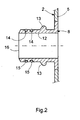
- the line 5 of the fresh air system 2 is equipped with the nozzle 8.
- the nozzle 8 can - as here - be sprayed onto the line 5.
- the nozzle 8 consists of a suitable plastic.
- the line 5 is made of a plastic. It is also possible to form the spigot 8 integrally on the conduit 5, that is, spigot 8 and conduit 5 are simultaneously formed in a tool, e.g. injection molded.
- a heating device suitable for this purpose may be provided, which, however, is not shown here.
- the nozzle 8 may also be a separately manufactured component which may be attached to the conduit 5 in any suitable manner.
- the nozzle 8 has an inlet portion 12 which is cylindrical or sleeve-shaped. At this inlet section 12, the connecting piece 8 has at least one laterally projecting barb 13. In the example shown, two such barbs 13 are provided, which are arranged diametrically opposite one another. The number of barbs 13 is basically arbitrary.
- the nozzle 8 is equipped at its inlet section 12 with at least one annular groove 14.
- two such annular grooves 14 are provided by way of example, each of which circulates closed on the outside at the inlet section 12.
- these annular grooves 14 each have a sealing ring 15 is inserted, preferably an O-ring.
- the annular grooves 14 and thus the sealing rings 15 are positioned between the barbs 13 and an inlet end 16 of the inlet section 12 and the connecting piece 8.
- the nozzle 8 is also chamfered here at its inlet end 16.
- the hose 7 has an outlet section 17, which is expediently cylindrically shaped.
- the hose 7 has at least one side opening 18 at its outlet section 17.
- two such side openings 18 are provided by way of example, which are diametrically opposed to one another. Appropriately agrees the number and arrangement of the barbs 13 with the number and arrangement of the side openings 18 match.
- the side openings 18 are characterized by a circumferentially closed edge 19, that is, the side openings 18 are each completely enclosed by the material of the outlet portion 17.
- the side openings 18 are dimensioned such that they each form a slot in the circumferential direction of the outlet section 17. Accordingly, the side openings 18 are sized larger in the circumferential direction of the exit portion 17 than in the axial direction of the peripheral portion 17. Preferably, the side openings 18 in the circumferential direction of the exit portion 17 each extend in a range of about 30 ° to 45 °.
- the tube 7 can subsequently have, at its outlet section 17, a section 20 which can be designed as a corrugated tube and thus has a certain flexibility.
- the tube 7 can be connected to the line 5, that the outlet portion 17 of the tube 7 is attached to the inlet portion 12 of the nozzle 8, such that each barb 13 engages in the associated side opening 18.
- the tube 7 is thereby secured to the nozzle 8.
- a gas-tight connection between the tube 7 and nozzle 8 is ensured by the seals 15.
- the hose 7 is like the nozzle 8 expediently made of plastic.
- the design of the tube 7, at least in the outlet section 17, preferably takes place in such a way that the outlet section 17 only deforms reversibly when it is plugged onto the inlet section 8, so that the barbs 13 in the side openings 18 in each case effectively engage behind an edge section 21 which extends from the side respective side opening 18 extends to the outlet end 22 of the tube 7.
- This reversible deformability of the outlet section 17 can be realized by a suitable dimensioning of the outlet section 17.
- the wall thickness of the outlet section 17 can accordingly be smaller than that of the inlet section 12.
- the deformability of the outlet section 17 can also be achieved or at least supported by a suitable material selection.
- the plastic of the tube 7 and the outlet portion 17 is preferably softer than the plastic of the nozzle 8. As a result, the outlet portion 17 yield during insertion and expand, while the stiffer nozzle 8 remains substantially dimensionally stable.
- the shape of the barbs 13 is suitably chosen so that they facilitate the expansion of the outlet portion 17 at least in the edge region 21 when plugging.
- the barbs 13 thus form an inclined ramp in the slip-on.
- the barbs 13 are also shaped so that they take off the hose 7 from Stutzen 8 complicate or prevent.
- the barbs 13 in the extension direction form a step which protrudes substantially radially.
- the engagement in the side opening 18 is characterized in terms of the achieved positive connection particularly effective.
- the barbs 13 in the circumferential direction of the inlet section 12 and the outlet section 17 are dimensioned smaller than the side openings 18. In this way, the rotational position between outlet section 17 and inlet section 12 can be changed, since the barbs 13 in the circumferential direction within the side openings 18 are adjustable.
- the connection of the tube 7 to the line 5 is considerably simplified since tolerance-related deviations between the rotational position of the outlet portion 17 relative to the inlet portion 12 can be compensated by the dimensioning of the slot-like side openings 18.
- the tube 7 For dismantling the tube 7, it can be suitably rotated in the circumferential direction, such that the barbs 13 displace the peripheral area delimiting the lateral openings 18 radially outward. Once the barbs 13 are unscrewed from the side openings 18, the hose 7 can be deducted from the nozzle 8.
- the barbs 13 in the circumferential direction at least on one side, for. Clockwise and / or counterclockwise, also have a ramp, which simplify the driving under and radial displacement of the outlet section 17 in the respective edge region of the side openings 18.
Landscapes
- Engineering & Computer Science (AREA)
- General Engineering & Computer Science (AREA)
- Mechanical Engineering (AREA)
- Chemical & Material Sciences (AREA)
- Combustion & Propulsion (AREA)
- Lubrication Details And Ventilation Of Internal Combustion Engines (AREA)
Abstract
Description
Die vorliegende Erfindung betrifft eine Brennkraftmaschine, insbesondere für ein Kraftfahrzeug, mit den Merkmalen des Oberbegriffs des Anspruchs 1. Die Erfindung betrifft außerdem eine Frischluftanlage sowie eine Entlüftungseinrichtung für eine derartige Brennkraftmaschine.The present invention relates to an internal combustion engine, in particular for a motor vehicle, with the features of the preamble of
Eine moderne Brennkraftmaschine, insbesondere für Kraftfahrzeuge, ist mit einer Frischluftanlage zur Versorgung der Brennkraftmaschine mit Frischluft sowie mit einer Entlüftungseinrichtung zum Abführen von Blow-By-Gasen aus der Brennkraftmaschine ausgestattet.A modern internal combustion engine, especially for motor vehicles, is equipped with a fresh air system for supplying the internal combustion engine with fresh air and with a venting device for discharging blow-by gases from the internal combustion engine.
Im Betrieb einer Kolben-Brennkraftmaschine gelangen Blow-By-Gase aufgrund unvermeidlicher Leckagen zwischen Kolben und Zylinder in ein Kurbelgehäuse der Brennkraftmaschine. Damit im Kurbelgehäuse kein unzulässig hoher Druck entsteht, werden die Blow-By-Gase mit Hilfe der Entlüftungseinrichtung abgeführt. Um dabei eine Umweltverschmutzung durch die schadstoffbeladenen Blow-By-Gase zu vermeiden, werden die Blow-By-Gase mit Hilfe der Entlüftungseinrichtung zweckmäßig der Frischluftanlage zugeführt, das heißt, die Blow-By-Gase werden erneut der Verbrennung der Brennkraftmaschine zugeführt. Zu diesem Zweck ist ein Schlauch der Entlüftungseinrichtung über einen Stutzen an eine Leitung der Frischluftanlage angeschlossen.During operation of a piston internal combustion engine, blow-by gases pass into a crankcase of the internal combustion engine due to unavoidable leaks between piston and cylinder. So that the crankcase no unacceptably high pressure, the blow-by gases are removed by means of the venting device. In order to avoid pollution by the pollutant-loaded blow-by gases, the blow-by gases with the help of the venting device are appropriate supplied to the fresh air system, that is, the blow-by gases are again supplied to the combustion of the internal combustion engine. For this purpose, a hose of the venting device is connected via a connecting piece to a line of the fresh air system.
Für die Montage der Brennkraftmaschine muss besagter Schlauch an den Stutzen der Leitung angeschlossen werden. Dieser Anschlussvorgang soll einhändig durchführbar sein, um Montagezeit zu sparen. Darüber hinaus muss der Schlauch wieder vom Stutzen zerstörungsfrei entfernt werden können, beispielsweise um Reparaturen durchführen zu können.For the installation of the internal combustion engine said hose must be connected to the nozzle of the pipe. This connection process should be feasible with one hand to save assembly time. In addition, the hose must be able to be removed again from the nozzle nondestructively, for example, to be able to carry out repairs.
Es ist ein Connector bekannt, der einerseits einen Schlauchanschluss und andererseits einen Stutzenanschluss aufweist. Der Schlauchanschluss ist widerhakenartig gestuft und weist eine umlaufende Ringnut auf, in der ein Dichtring angeordnet ist. Auf diesen Schlauchanschluss kann ein Austrittsabschnitt des Schlauchs aufgesteckt werden, um diesen fest und bleibend mit dem Connector zu verbinden. Hierzu wird der Austrittabschnitts des Schlauchs auf den Schlauchanschluss des Connectors "aufgeschossen", das bedeutet, dass der Schlauch zumindest in seinem Austrittsabschnitt erwärmt und anschließend auf den Schlauchanschluss angesteckt wird, wobei sich der Austrittsabschnitt aufgrund der erhöhten Temperatur leicht elastisch aufweiten lässt. Beim anschließenden Abkühlen schrumpft der Austrittsabschnitt stark zusammen und verhärtet sich, wodurch quasi eine Formschlussverbindung über die Stufen des Schlauchanschlusses realisiert wird. Die Verbindung zwischen Schlauch und Connector besitzt eine hohe Auszugsfestigkeit und ist nicht für ein lösbares Entfernen des Schlauchs vom Connector vorgesehen.It is a connector known, on the one hand has a hose connection and on the other hand, a nozzle connection. The hose connection is barb-like and has a circumferential annular groove in which a sealing ring is arranged. An outlet section of the hose can be attached to this hose connection in order to connect it firmly and permanently to the connector. For this purpose, the outlet section of the hose is "shot" onto the hose connection of the connector, this means that the hose is heated at least in its outlet section and subsequently plugged onto the hose connection, wherein the outlet section can be easily elastically expanded due to the elevated temperature. During the subsequent cooling, the outlet section shrinks sharply and hardens, as a result of which, as it were, a positive connection is achieved via the steps of the hose connection. The Connection between hose and connector has a high pull-out strength and is not intended for a detachable removal of the hose from the connector.
Im Unterschied dazu ist der Stutzenanschluss des Connectors mit einer lösbaren Verrastung versehen, die beim Aufstecken des Stutzenanschlusses auf den Stutzen am Stutzen selbsttätig einrastet. Zum Lösen dieser Steckverbindung wird die Verrastung auf geeignete Weise gelöst, so dass der Stutzenanschluss zerstörungsfrei vom Stutzen abgezogen werden kann. Im Stutzenanschluss sind weitere Dichtringe angeordnet, die im montierten Zustand mit dem eingesteckten Stutzen zusammenwirken.In contrast, the nozzle connection of the connector is provided with a releasable catch, which automatically engages when connecting the nozzle connection to the nozzle on the nozzle. To release this connector, the locking is achieved in a suitable manner, so that the nozzle connection can be removed from the nozzle nondestructive. In the nozzle connection further sealing rings are arranged, which cooperate in the assembled state with the inserted nozzle.
Mit Hilfe des bekannten Connectors kann der Schlauch der Entlüftungseinrichtung einfach über den Stutzen an die Leitung der Frischluftanlage angeschlossen werden. Auch die Demontage ist einfach und zerstörungsfrei realisierbar. Nachteilig ist jedoch, dass ein derartiger Connector relativ teuer ist.With the help of the known connector, the hose of the venting device can be easily connected via the nozzle to the line of the fresh air system. The disassembly is easy and non-destructive realizable. The disadvantage, however, is that such a connector is relatively expensive.
Die vorliegende Erfindung beschäftigt sich mit dem Problem, für das Anschließen des Schlauchs der Entlüftungseinrichtung über den Stutzen an die Leitung der Frischluftanlage einen preiswerten Weg aufzuzeigen.The present invention is concerned with the problem of pointing for the connection of the hose of the venting device via the pipe to the line of the fresh air system a cheap way.
Dieses Problem wird erfindungsgemäß durch die Gegenstände der unabhängigen Ansprüche gelöst. Vorteilhafte Ausführungsformen sind Gegenstand der abhängigen Ansprüche.This problem is solved according to the invention by the subject matters of the independent claims. Advantageous embodiments are the subject of the dependent claims.
Die Erfindung beruht auf dem allgemeinen Gedanken, den Schlauch mit seinem Austrittsabschnitt direkt auf den Eintrittsabschnitt des Stutzens aufzustecken und zur Sicherung wenigstens eine fensterartige Seitenöffnung im Austrittsabschnitt vorzusehen, in welche ein am Eintrittsabschnitt ausgebildeter Widerhaken eingreift. Auf einen Connector, der quasi einen fest mit dem Schlauch verbundenen und lösbar auf den Stutzen aufsteckbaren Adapter bildet, kann somit verzichtet werden. Des Weiteren lassen sich Seitenöffnungen im Austrittsabschnitt des Schlauchs preiswert herstellen. Ebenso können Widerhaken am Eintrittsabschnitt des Stutzens preiswert ausgebildet werden. Der sich durch die Erfindung ergebende Preisvorteil liegt auf der Hand.The invention is based on the general idea to place the hose with its outlet section directly on the inlet section of the nozzle and to provide at least one window-like side opening in the outlet section for securing, in which engages a barb formed on the inlet section. Can thus be dispensed with a connector that virtually forms a permanently connected to the hose and releasably attachable to the nozzle adapter. Furthermore, side openings in the outlet section of the hose can be produced inexpensively. Likewise, barbs can be formed inexpensively at the inlet portion of the nozzle. The price advantage resulting from the invention is obvious.
Zweckmäßig ist der Schlauch zumindest in seinem Austrittsabschnitt, beispielsweise durch Formgebung und/oder Materialauswahl, so ausgestaltet, dass er sich beim Aufstecken auf den Eintrittsabschnitt des Stutzens reversibel verformt. Durch diese Bauweise werden zum einen Beschädigungen des Schlauchs beim Aufstecken auf den Stutzen vermieden, zum anderen wird dadurch eine beschädigungsfreie Entfernung des Schlauchs vom Stutzen vereinfacht.The hose is expediently designed, at least in its outlet section, for example by shaping and / or material selection, such that it reversibly deforms when being attached to the inlet section of the connecting piece. By this construction, on the one hand damage to the hose when plugging the nozzle are avoided, on the other hand, a damage-free removal of the hose from the nozzle is simplified.
Gemäß einer vorteilhaften Ausführungsform kann die wenigstens eine Seitenöffnung in der Umfangsrichtung des Austrittsabschnitts als Langloch ausgestaltet sein, das sich vorzugsweise über 30° bis 45° erstrecken kann. Durch die Ausführung der wenigstens einen Seitenöffnung als Langloch, lässt sich der Schlauch in unterschiedlichen Drehlagen am Stutzen montieren, sofern dann der wenigstens eine Widerhaken in Umfangsrichtung entsprechend kleiner dimensioniert ist als die jeweilige Seitenöffnung. Diese Maßnahme vereinfacht die Montage, da herstellungsbedingte Toleranzen ausgeglichen werden können.According to an advantageous embodiment, the at least one side opening in the circumferential direction of the outlet section may be designed as a slot, which may preferably extend over 30 ° to 45 °. By the execution of at least one side opening as a slot, can be the hose mounted in different rotational positions on the neck, if then the at least one barb in the circumferential direction is dimensioned correspondingly smaller than the respective side opening. This measure simplifies the assembly, since manufacturing tolerances can be compensated.
Weitere wichtige Merkmale und Vorteile der Erfindung ergeben sich aus den Unteransprüchen, aus den Zeichnungen und aus der zugehörigen Figurenbeschreibung anhand der Zeichnungen.Other important features and advantages of the invention will become apparent from the dependent claims, from the drawings and from the associated figure description with reference to the drawings.
Es versteht sich, dass die vorstehend genannten und die nachstehend noch zu erläuternden Merkmale nicht nur in der jeweils angegebenen Kombination, sondern auch in anderen Kombinationen oder in Alleinstellung verwendbar sind, ohne den Rahmen der vorliegenden Erfindung zu verlassen.It is understood that the features mentioned above and those yet to be explained below can be used not only in the particular combination given, but also in other combinations or in isolation, without departing from the scope of the present invention.
Ein bevorzugtes Ausführungsbeispiel der Erfindung ist in den Zeichnungen dargestellt und wird in der nachfolgenden Beschreibung näher erläutert, wobei sich gleiche Bezugszeichen auf gleiche oder ähnliche oder funktional gleiche Bauteile beziehen.A preferred embodiment of the invention is illustrated in the drawings and will be explained in more detail in the following description, wherein like reference numerals refer to the same or similar or functionally identical components.
Es zeigen, jeweils schematisch,
- Fig. 1
- eine stark vereinfachte, schaltplanartige Prinzipdarstellung einer Brennkraftmaschine nach der findung,
- Fig. 2
- einen vereinfachten Längsschnitt im Bereich eines Stutzens einer Frischluftanlage nach der Erfindung,
- Fig. 3
- einen vereinfachten Längsschnitt im Bereich eines Schlauchs einer Entlüftungseinrichtung nach der Erfindung,
- Fig. 4
- einen Längsschnitt wie in den Fig. 2 und 3, jedoch bei auf den Stutzen aufgestecktem Schlauch.
- Fig. 1
- a greatly simplified schematic diagram of an internal combustion engine according to the invention,
- Fig. 2
- a simplified longitudinal section in the region of a nozzle of a fresh air system according to the invention,
- Fig. 3
- a simplified longitudinal section in the region of a hose of a venting device according to the invention,
- Fig. 4
- a longitudinal section as shown in FIGS. 2 and 3, but with the tube plugged on the tube.
Entsprechend Fig. 1 ist eine erfindungsgemäße Brennkraftmaschine 1, insbesondere für ein Kraftfahrzeug, mit einer Frischluftanlage 2, mit einer Entlüftungseinrichtung 3 und zweckmäßig mit einer Abgasanlage 4 ausgestattet. Die Frischluftanlage 2 dient zur Versorgung der Brennkraftmaschine 1 mit Frischluft und umfasst zumindest eine Leitung 5. Die Frischluftanlage 2 kann dabei in üblicher Weise weitere, hier nicht gezeigte Komponenten, wie z.B. eine Frischluftfilter, enthalten.1, an
Die Entlüftungseinrichtung 3 dient zum Abführen von Blow-By-Gasen aus der Brennkraftmaschine 1. Die Entlüftungseinrichtung 3 ist dazu einenends an einen Motorblock 6 der Brennkraftmaschine 1 angeschlossen und kommuniziert dort mit einem Kurbelgehäuse. Anderenends weist die Entlüftungseinrichtung 3 einen Schlauch 7 auf, der über einen Stutzen 8 an die Leitung 5 angeschlossen ist. Die durch Pfeile symbolisierten Blow-By-Gase 9 können auf diese Weise der ebenfalls durch Pfeile symbolisierten Frischluft 10 zugeführt werden. Die Entlüftungseinrichtung 3 kann in üblicher Weise weitere, hier nicht gezeigte Komponenten, wie z. B. ein Tröpfchenabscheider, aufweisen.The
Die Abgasanlage 4 dient zum Abführen von durch einen Pfeil angedeuteten Verbrennungsabgasen 11 aus der Brennkraftmaschine 1. Auch die Abgasanlage 4 kann weitere, hier nicht dargestellte Komponenten, wie z.B. Schalldämpfer, Katalysator, Partikelfilter, aufweisen.The
Entsprechend Fig. 2 ist die Leitung 5 der Frischluftanlage 2 mit dem Stutzen 8 ausgestattet. Der Stutzen 8 kann - wie hier - an die Leitung 5 angespritzt sein. Der Stutzen 8 besteht dabei aus einem geeigneten Kunststoff. Zweckmäßig besteht auch die Leitung 5 aus einem Kunststoff. Ebenso ist es möglich, den Stutzen 8 integral an der Leitung 5 auszuformen, das heißt, Stutzen 8 und Leitung 5 werden gleichzeitig in einem Werkzeug ausgeformt, z.B. spritzgeformt.According to Fig. 2, the
Des Weiteren können im Bereich des Stutzens 8 diverse Vorkehrungen getroffen werden, um eine Eisbildung im Mündungsbereich zwischen Stutzen 8 und Leitung 5 zu vermeiden. Beispielsweise kann eine hierzu geeignete Heizeinrichtung vorgesehen sein, die hier jedoch nicht dargestellt ist.Furthermore, various provisions can be made in the area of the
Der Stutzen 8 kann auch ein separat hergestelltes Bauteil sein, das auf eine beliebige, geeignete Weise an der Leitung 5 angebracht sein kann.The
Der Stutzen 8 weist einen Eintrittsabschnitt 12 auf, der zylindrisch oder hülsenförmig gestaltet ist. An diesem Eintrittsabschnitt 12 weist der Stutzen 8 zumindest einen seitlich abstehenden Widerhaken 13 auf. Im gezeigten Beispiel sind zwei derartige Widerhaken 13 vorgesehen, die diametral gegenüberliegend angeordnet sind. Die Anzahl der Widerhaken 13 ist dabei grundsätzlich beliebig.The
Des Weiteren ist der Stutzen 8 an seinem Eintrittsabschnitt 12 mit wenigstens einer Ringnut 14 ausgestattet. Im gezeigten Beispiel sind exemplarisch zwei derartige Ringnuten 14 vorgesehen, die jeweils außen am Eintrittsabschnitt 12 geschlossen umlaufen. In diesen Ringnuten 14 ist jeweils ein Dichtring 15 eingesetzt, vorzugsweise ein O-Ring. Die Ringnuten 14 und somit die Dichtringe 15 sind dabei zwischen den Widerhaken 13 und einem Eintrittsende 16 des Eintrittsabschnitts 12 bzw. des Stutzens 8 positioniert. Um den Schlauch 7 besser auf den Stutzen 8 aufsetzen zu können, ist der Stutzen 8 hier an seinem Eintrittsende 16 außerdem angefast.Furthermore, the
Entsprechend Fig. 3 weist der Schlauch 7 einen Austrittsabschnitt 17 auf, der zweckmäßig zylindrisch geformt ist. Erfindungsgemäß weist der Schlauch 7 an seinem Austrittsabschnitt 17 zumindest eine Seitenöffnung 18 auf. Im vorliegenden Beispiel sind exemplarisch zwei derartige Seitenöffnungen 18 vorgesehen, die einander diametral gegenüberliegen. Zweckmäßig stimmt die Anzahl und Anordnung der Widerhaken 13 mit der Anzahl und Anordnung der Seitenöffnungen 18 überein. Die Seitenöffnungen 18 charakterisieren sich durch einen umfangsmäßig geschlossenen Rand 19, das heißt, die Seitenöffnungen 18 sind jeweils vollständig vom Werkstoff des Austrittsabschnitts 17 umschlossen.According to FIG. 3, the
Gemäß der hier gezeigten, bevorzugten Ausführungsform sind die Seitenöffnungen 18 so dimensioniert, dass sie in der Umfangsrichtung des Austrittsabschnitts 17 jeweils ein Langloch bilden. Dementsprechend sind die Seitenöffnungen 18 in der Umfangsrichtung des Austrittsabschnitts 17 größer dimensioniert als in der Achsrichtung des Umfangsabschnitts 17. Vorzugsweise erstrecken sich die Seitenöffnungen 18 in der Umfangsrichtung des Austrittsabschnitts 17 jeweils in einem Bereich von etwa 30° bis 45°.According to the preferred embodiment shown here, the
Der Schlauch 7 kann wie bei der hier gezeigten Ausführungsform anschließend an seinen Austrittsabschnitt 17 einen Abschnitt 20 aufweisen, der als Wellschlauch ausgestaltet sein kann und dadurch eine gewisse Flexibilität aufweist.As in the case of the embodiment shown here, the
Entsprechend Fig. 4 kann der Schlauch 7 dadurch an die Leitung 5 angeschlossen werden, dass der Austrittsabschnitt 17 des Schlauchs 7 auf den Eintrittsabschnitt 12 des Stutzens 8 aufgesteckt wird, derart, dass jeder Widerhaken 13 in die zugehörige Seitenöffnung 18 eingreift. Der Schlauch 7 ist dadurch am Stutzen 8 gesichert. Eine gasdichte Verbindung zwischen Schlauch 7 und Stutzen 8 wird über die Dichtungen 15 gewährleistet. Der Schlauch 7 ist wie der Stutzen 8 zweckmäßig aus Kunststoff hergestellt. Die Gestaltung des Schlauchs 7, zumindest im Austrittsabschnitt 17, erfolgt vorzugsweise so, dass sich der Austrittsabschnitt 17 beim Aufstecken auf den Eintrittsabschnitt 8 nur reversibel verformt, so dass die Widerhaken 13 in den Seitenöffnungen 18 jeweils einen Randabschnitt 21 effektiv hintergreifen, der sich von der jeweiligen Seitenöffnung 18 bis zum Austrittsende 22 des Schlauchs 7 erstreckt.4, the
Diese reversible Verformbarkeit des Austrittsabschnitts 17 kann durch eine geeignete Dimensionierung des Austrittsabschnitts 17 realisiert werden. Die Wandstärke des Austrittsabschnitts 17 kann dementsprechend geringer sein als diejenige des Eintrittsabschnitts 12. Zusätzlich oder alternativ kann die Verformbarkeit des Austrittsabschnitts 17 auch durch eine geeignete Materialauswahl erreicht oder zumindest unterstützt werden. Vorzugsweise ist somit der Kunststoff des Schlauchs 7 bzw. des Austrittsabschnitts 17 weicher als der Kunststoff des Stutzens 8. In der Folge kann der Austrittsabschnitt 17 beim Aufstecken nachgeben und sich ausweiten, während der steifere Stutzen 8 im wesentlichen formstabil bleibt.This reversible deformability of the
Die Formgebung der Widerhaken 13 ist zweckmäßig so gewählt, dass sie beim Aufstecken das Aufweiten des Austrittsabschnitts 17 zumindest im Randbereich 21 erleichtern. Die Widerhaken 13 bilden somit in der Aufsteckrichtung eine geneigte Rampe. Im Unterschied dazu sind die Widerhaken 13 außerdem so geformt, dass sie das Abziehen des Schlauchs 7 vom Stutzen 8 erschweren oder verhindern. Beim gezeigten Beispiel bilden die Widerhaken 13 in der Auszugsrichtung eine Stufe, die im wesentlichen radial absteht. Der Eingriff in die Seitenöffnung 18 wird dadurch hinsichtlich des erzielten Formschlusses besonders effektiv.The shape of the
Vorzugsweise sind die Widerhaken 13 in der Umfangsrichtung des Eintrittsabschnitts 12 bzw. des Austrittsabschnitts 17 kleiner dimensioniert als die Seitenöffnungen 18. Hierdurch kann die Drehlage zwischen Austrittsabschnitt 17 und Eintrittsabschnitt 12 verändert werden, da die Widerhaken 13 in der Umfangsrichtung innerhalb der Seitenöffnungen 18 verstellbar sind. Durch diese Bauweise ist das Anschließen des Schlauchs 7 an die Leitung 5 erheblich vereinfacht, da toleranzbedingte Abweichungen zwischen der Drehlage des Austrittsabschnitts 17 relativ zum Eintrittsabschnitt 12 durch die Dimensionierung der langlochartigen Seitenöffnungen 18 ausgeglichen werden können.Preferably, the
Zum Demontieren des Schlauchs 7 kann dieser zweckmäßig in der Umfangsrichtung gedreht werden, derart, dass die Widerhaken 13 den die Seitenöffnungen 18 in Umfangsrichtung begrenzenden Randbereich radial nach außen verdrängen. Sobald die Widerhaken 13 aus den Seitenöffnungen 18 herausgedreht sind, kann der Schlauch 7 vom Stutzen 8 abgezogen werden. Um das Ausdrehen der Widerhaken 13 aus den Seitenöffnungen 18 zu erleichtern, können die Widerhaken 13 in der Umfangsrichtung zumindest an einer Seite, z. B. im Uhrzeigersinn und/oder im Gegenuhrzeigersinn, ebenfalls eine Rampe aufweisen, die das Unterfahren und radiale Verdrängen des Austrittsabschnitts 17 im jeweiligen Randbereich der Seitenöffnungen 18 vereinfachen.For dismantling the
Claims (11)
dadurch gekennzeichnet,
dass der Stutzen (8) am Eintrittsabschnitt (12) zwischen dem wenigstens einen Widerhaken (13) und einem Eintrittsende (16) des Stutzens (8) wenigstens eine umlaufende Ringnut (14) aufweist, in der ein Dichtring (15) angeordnet ist.Internal combustion engine according to claim 1,
characterized,
that the connecting piece (8) of the connecting piece (8) has at least one circumferential annular groove (14) at the inlet portion (12) between the at least one barb (13) and an entrance end (16), in which a sealing ring (15) is arranged.
dadurch gekennzeichnet,
characterized,
dadurch gekennzeichnet,
characterized,
dadurch gekennzeichnet,
dass der Schlauch (7) zumindest in seinem Austrittsabschnitt (17) so ausgestaltet ist, dass er sich beim Aufstecken auf den Eintrittsabschnitt (12) des Stutzens (8) reversibel verformt.Internal combustion engine according to one of claims 1 to 4,
characterized,
that the tube (7) is designed at least in its exit section (17) so that it deforms during insertion of the entry portion (12) of the connecting piece (8) is reversible.
dadurch gekennzeichnet,
dass die wenigstens eine Seitenöffnung (18) in der Umfangsrichtung des Austrittsabschnitts (17) als Langloch ausgestaltet ist.Internal combustion engine according to one of claims 1 to 5,
characterized,
that the one side opening (18) is at least designed as a long hole in the circumferential direction of the exit portion (17).
dadurch gekennzeichnet,
dass sich die wenigstens eine Seitenöffnung (18) in der Umfangsrichtung des Austrittsabschnitts (17) etwa in einem Winkelbereich von 30° bis 45° erstreckt.Internal combustion engine according to one of claims 1 to 6,
characterized,
in that the at least one side opening (18) extends in the circumferential direction of the outlet section (17) approximately in an angular range of 30 ° to 45 °.
dadurch gekennzeichnet,
dass der Stutzen (8) an einem Eintrittsabschnitt (12) wenigstens einen seitlich abstehenden Widerhaken (13) aufweist.Fresh air system for supplying an internal combustion engine (1) with fresh air (10), in particular for a motor vehicle, with a line (5), to which via a nozzle (8) a hose (7) a venting device (13) for discharging blow-by Gases (9) from the internal combustion engine (1) can be connected to supply blow-by gases (9) of the fresh air (10),
characterized,
that the connecting piece (8) has at least one laterally projecting barbs (13) at an entrance portion (12).
gekennzeichnet durch die kennzeichnenden Merkmale wenigstens eines der Ansprüche 2 und 3.Fresh air installation according to claim 8,
characterized by the characterizing features of at least one of claims 2 and 3. FIG.
dadurch gekennzeichnet,
dass der Schlauch (7) an einem Austrittsabschnitt (17) wenigstens eine Seitenöffnung (18) mit umfangsmäßig geschlossenem Rand (19) aufweist.Venting device for discharging blow-by gases (9) from an internal combustion engine (1), in particular for a motor vehicle, with a hose (7), which via a connecting piece (8) to a line (5) of a fresh air system (2) for supplying the internal combustion engine (1) with fresh air (10) can be connected to supply blow-by gases (9) of the fresh air (10),
characterized,
that the tube (7) at an exit portion (17) at least one side opening (18) with a circumferentially continuous rim (19).
Applications Claiming Priority (1)
| Application Number | Priority Date | Filing Date | Title |
|---|---|---|---|
| DE102004063459A DE102004063459A1 (en) | 2004-12-23 | 2004-12-23 | Internal combustion engine with fresh air system and ventilation device |
Publications (3)
| Publication Number | Publication Date |
|---|---|
| EP1674679A2 true EP1674679A2 (en) | 2006-06-28 |
| EP1674679A3 EP1674679A3 (en) | 2007-04-18 |
| EP1674679B1 EP1674679B1 (en) | 2016-02-17 |
Family
ID=36072003
Family Applications (1)
| Application Number | Title | Priority Date | Filing Date |
|---|---|---|---|
| EP05109490.2A Expired - Fee Related EP1674679B1 (en) | 2004-12-23 | 2005-10-12 | Combustion engine with fresh air and ventilating system |
Country Status (2)
| Country | Link |
|---|---|
| EP (1) | EP1674679B1 (en) |
| DE (1) | DE102004063459A1 (en) |
Cited By (9)
| Publication number | Priority date | Publication date | Assignee | Title |
|---|---|---|---|---|
| WO2011006584A3 (en) * | 2009-07-16 | 2011-04-14 | Rheinmetall Landsysteme Gmbh | Hose connector |
| WO2011120797A1 (en) * | 2010-03-30 | 2011-10-06 | Mahle International Gmbh | Coupling device, crankcase ventilation device and fresh-air system |
| EP2407698A3 (en) * | 2010-07-13 | 2013-08-21 | MAHLE International GmbH | Coupling device, crankcase ventilation device and fresh air system |
| EP2837530A1 (en) * | 2013-08-12 | 2015-02-18 | Continental Automotive GmbH | Impact sensor having an elastically deformable hose and pressure sensor and radial opening in the hose for attachment |
| CN107012924A (en) * | 2017-05-31 | 2017-08-04 | 福建省天力卫浴科技有限公司 | A kind of compact sink sewage system |
| CN107869618A (en) * | 2017-11-30 | 2018-04-03 | 西安交通大学 | Comb attachment structure in a kind of freezer compressor |
| WO2019104715A1 (en) | 2017-12-01 | 2019-06-06 | Mann+Hummel Gmbh | Fluid duct arrangement and connectors for a fluid duct |
| DE102019001812A1 (en) * | 2019-03-15 | 2020-09-17 | Volkswagen Aktiengesellschaft | Tube-hose arrangement |
| JP2021095877A (en) * | 2019-12-17 | 2021-06-24 | 株式会社クボタ | Intake system for engine |
Families Citing this family (5)
| Publication number | Priority date | Publication date | Assignee | Title |
|---|---|---|---|---|
| DE102007017668A1 (en) | 2007-04-14 | 2008-10-16 | Bayerische Motoren Werke Aktiengesellschaft | Charged internal combustion engine and method for monitoring whether the crankcase breather has been connected |
| DE102007056167A1 (en) * | 2007-11-21 | 2009-05-28 | Bombardier Transportation Gmbh | Connection arrangement for connecting air guiding line sections of air circulation system in vehicles, particularly rail vehicles, has adapter, which is provided in air duct, and arranged in air supply |
| DE102014211844A1 (en) | 2014-06-20 | 2015-12-24 | Contitech Mgw Gmbh | Coupling element for flexible connection of two elements for guiding media |
| DE102017215896A1 (en) | 2017-09-08 | 2019-03-14 | Mahle International Gmbh | Hose connection with elastomer hose |
| DE102017221735A1 (en) | 2017-12-01 | 2019-06-06 | Volkswagen Aktiengesellschaft | Arrangement for diverting blow-by gases from a crankcase of an internal combustion engine |
Citations (6)
| Publication number | Priority date | Publication date | Assignee | Title |
|---|---|---|---|---|
| DE3918785A1 (en) * | 1989-06-08 | 1990-12-13 | Bayerische Motoren Werke Ag | IC engine air intake manifold - has branched air intake chamber and oil separator in crankcase ventilation system |
| DE3932300A1 (en) * | 1989-09-28 | 1991-04-11 | Vdo Schindling | Connection between throttle tube and crankcase - incorporates press-fit pipe with swaged ridges |
| GB2263956A (en) * | 1992-02-04 | 1993-08-11 | Ford Motor Co | A push-on pipe joint |
| FR2738035A1 (en) * | 1995-08-25 | 1997-02-28 | Renault | IC engine intake manifold with grouped auxiliary vacuum connections |
| DE29818787U1 (en) * | 1998-10-22 | 1999-01-28 | Truplast Kunststofftechnik | Arrangement for releasably connecting a hose to a connecting sleeve |
| EP1306542A1 (en) * | 2001-10-24 | 2003-05-02 | Wecosta | Air filter, intake conduit and assembly of such a filter with such an intake conduit |
Family Cites Families (2)
| Publication number | Priority date | Publication date | Assignee | Title |
|---|---|---|---|---|
| DE1601384A1 (en) * | 1968-02-13 | 1970-11-05 | Hanomag Henschel Fahrzeug | Crankcase ventilation of engines, in particular diesel engines |
| DE19938189C2 (en) * | 1999-08-17 | 2002-11-28 | Kautex Textron Gmbh & Co Kg | Coolant pipe for internal combustion engines and method for producing the same |
-
2004
- 2004-12-23 DE DE102004063459A patent/DE102004063459A1/en not_active Withdrawn
-
2005
- 2005-10-12 EP EP05109490.2A patent/EP1674679B1/en not_active Expired - Fee Related
Patent Citations (6)
| Publication number | Priority date | Publication date | Assignee | Title |
|---|---|---|---|---|
| DE3918785A1 (en) * | 1989-06-08 | 1990-12-13 | Bayerische Motoren Werke Ag | IC engine air intake manifold - has branched air intake chamber and oil separator in crankcase ventilation system |
| DE3932300A1 (en) * | 1989-09-28 | 1991-04-11 | Vdo Schindling | Connection between throttle tube and crankcase - incorporates press-fit pipe with swaged ridges |
| GB2263956A (en) * | 1992-02-04 | 1993-08-11 | Ford Motor Co | A push-on pipe joint |
| FR2738035A1 (en) * | 1995-08-25 | 1997-02-28 | Renault | IC engine intake manifold with grouped auxiliary vacuum connections |
| DE29818787U1 (en) * | 1998-10-22 | 1999-01-28 | Truplast Kunststofftechnik | Arrangement for releasably connecting a hose to a connecting sleeve |
| EP1306542A1 (en) * | 2001-10-24 | 2003-05-02 | Wecosta | Air filter, intake conduit and assembly of such a filter with such an intake conduit |
Non-Patent Citations (1)
| Title |
|---|
| ANONYMOUS: "Freeze resistant intake manifold fitting for PCV systems" RESEARCH DISCLOSURE, MASON PUBLICATIONS, HAMPSHIRE, GB, Bd. 399, Nr. 36, Juli 1997 (1997-07), XP007121886 ISSN: 0374-4353 * |
Cited By (12)
| Publication number | Priority date | Publication date | Assignee | Title |
|---|---|---|---|---|
| WO2011006584A3 (en) * | 2009-07-16 | 2011-04-14 | Rheinmetall Landsysteme Gmbh | Hose connector |
| WO2011120797A1 (en) * | 2010-03-30 | 2011-10-06 | Mahle International Gmbh | Coupling device, crankcase ventilation device and fresh-air system |
| CN102822458A (en) * | 2010-03-30 | 2012-12-12 | 马勒国际有限公司 | Coupling device, crankcase ventilation device and fresh-air system |
| CN106930870A (en) * | 2010-03-30 | 2017-07-07 | 马勒国际有限公司 | Coupling arrangement, crankcase bleeder and VMC |
| EP2407698A3 (en) * | 2010-07-13 | 2013-08-21 | MAHLE International GmbH | Coupling device, crankcase ventilation device and fresh air system |
| US8727382B2 (en) | 2010-07-13 | 2014-05-20 | Mahle International Gmbh | Coupling device, crankcase ventilation device and fresh air system |
| EP2837530A1 (en) * | 2013-08-12 | 2015-02-18 | Continental Automotive GmbH | Impact sensor having an elastically deformable hose and pressure sensor and radial opening in the hose for attachment |
| CN107012924A (en) * | 2017-05-31 | 2017-08-04 | 福建省天力卫浴科技有限公司 | A kind of compact sink sewage system |
| CN107869618A (en) * | 2017-11-30 | 2018-04-03 | 西安交通大学 | Comb attachment structure in a kind of freezer compressor |
| WO2019104715A1 (en) | 2017-12-01 | 2019-06-06 | Mann+Hummel Gmbh | Fluid duct arrangement and connectors for a fluid duct |
| DE102019001812A1 (en) * | 2019-03-15 | 2020-09-17 | Volkswagen Aktiengesellschaft | Tube-hose arrangement |
| JP2021095877A (en) * | 2019-12-17 | 2021-06-24 | 株式会社クボタ | Intake system for engine |
Also Published As
| Publication number | Publication date |
|---|---|
| EP1674679A3 (en) | 2007-04-18 |
| DE102004063459A1 (en) | 2006-07-06 |
| EP1674679B1 (en) | 2016-02-17 |
Similar Documents
| Publication | Publication Date | Title |
|---|---|---|
| EP1674679B1 (en) | Combustion engine with fresh air and ventilating system | |
| EP1924801B1 (en) | Coupling system | |
| EP1953359B1 (en) | Exhaust system for an internal combustion engine | |
| DE102008052552A1 (en) | Turbine housing and method for its production | |
| DE102013001389A1 (en) | Crankcase breather for an internal combustion engine, tank vent line and Verbindungssytem this | |
| EP1818533A2 (en) | Safety system for a hydrocarbon trap | |
| EP3303816B1 (en) | Vehicle silencer | |
| DE102008046143A1 (en) | Quick-coupler arrangement for use in cooling circuit of internal-combustion engine of motor vehicle to connect e.g. cooling water hose, has separation force producing device producing force that acts between connecting piece and coupler | |
| WO2003048557A1 (en) | Intake air filter for an internal combustion engine | |
| DE102013011086A1 (en) | Filter element and method for producing a filter element | |
| EP2165104A1 (en) | Charge-air hose | |
| EP2072103B1 (en) | Filter cartridge and oil filter of a combustion motor | |
| EP0943365A1 (en) | Sealing for ring filter inside a filter housing | |
| EP2133615B1 (en) | Coupling device, in particular for a fresh-air supply system | |
| DE102012220792A1 (en) | Heat exchanger arrangement, in particular for a vehicle heater | |
| DE102011118862A1 (en) | Modular flange | |
| EP2596271A1 (en) | Locking device for a connecting arrangement | |
| WO2011120797A1 (en) | Coupling device, crankcase ventilation device and fresh-air system | |
| EP2616649B1 (en) | Exhaust gas treatment unit, in particular for an exhaust gas recirculation line | |
| EP1726794A1 (en) | Exhaust gas silencer and method of manufacturing | |
| DE102004024465A1 (en) | intake system | |
| EP1058782B1 (en) | Intake device for an internal combustion engine | |
| EP3798530B1 (en) | Housing for removing condensate of a heating device and heating device comprising such a housing | |
| DE102018001137B3 (en) | Engine assembly | |
| DE19651188C2 (en) | Fuel supply unit |
Legal Events
| Date | Code | Title | Description |
|---|---|---|---|
| PUAI | Public reference made under article 153(3) epc to a published international application that has entered the european phase |
Free format text: ORIGINAL CODE: 0009012 |
|
| AK | Designated contracting states |
Kind code of ref document: A2 Designated state(s): AT BE BG CH CY CZ DE DK EE ES FI FR GB GR HU IE IS IT LI LT LU LV MC NL PL PT RO SE SI SK TR |
|
| AX | Request for extension of the european patent |
Extension state: AL BA HR MK YU |
|
| PUAL | Search report despatched |
Free format text: ORIGINAL CODE: 0009013 |
|
| RIC1 | Information provided on ipc code assigned before grant |
Ipc: F02M 35/10 20060101ALN20070301BHEP Ipc: F01M 13/00 20060101AFI20060329BHEP Ipc: F16L 33/22 20060101ALI20070301BHEP Ipc: F16L 37/113 20060101ALI20070301BHEP Ipc: F02M 25/06 20060101ALI20070301BHEP |
|
| AK | Designated contracting states |
Kind code of ref document: A3 Designated state(s): AT BE BG CH CY CZ DE DK EE ES FI FR GB GR HU IE IS IT LI LT LU LV MC NL PL PT RO SE SI SK TR |
|
| AX | Request for extension of the european patent |
Extension state: AL BA HR MK YU |
|
| 17P | Request for examination filed |
Effective date: 20071006 |
|
| AKX | Designation fees paid |
Designated state(s): DE FR GB |
|
| 17Q | First examination report despatched |
Effective date: 20091008 |
|
| GRAP | Despatch of communication of intention to grant a patent |
Free format text: ORIGINAL CODE: EPIDOSNIGR1 |
|
| INTG | Intention to grant announced |
Effective date: 20150901 |
|
| GRAS | Grant fee paid |
Free format text: ORIGINAL CODE: EPIDOSNIGR3 |
|
| GRAA | (expected) grant |
Free format text: ORIGINAL CODE: 0009210 |
|
| AK | Designated contracting states |
Kind code of ref document: B1 Designated state(s): DE FR GB |
|
| REG | Reference to a national code |
Ref country code: GB Ref legal event code: FG4D Free format text: NOT ENGLISH |
|
| REG | Reference to a national code |
Ref country code: DE Ref legal event code: R096 Ref document number: 502005015113 Country of ref document: DE |
|
| REG | Reference to a national code |
Ref country code: DE Ref legal event code: R097 Ref document number: 502005015113 Country of ref document: DE |
|
| PLBE | No opposition filed within time limit |
Free format text: ORIGINAL CODE: 0009261 |
|
| STAA | Information on the status of an ep patent application or granted ep patent |
Free format text: STATUS: NO OPPOSITION FILED WITHIN TIME LIMIT |
|
| 26N | No opposition filed |
Effective date: 20161118 |
|
| REG | Reference to a national code |
Ref country code: DE Ref legal event code: R084 Ref document number: 502005015113 Country of ref document: DE |
|
| GBPC | Gb: european patent ceased through non-payment of renewal fee |
Effective date: 20161012 |
|
| REG | Reference to a national code |
Ref country code: FR Ref legal event code: ST Effective date: 20170630 |
|
| PG25 | Lapsed in a contracting state [announced via postgrant information from national office to epo] |
Ref country code: GB Free format text: LAPSE BECAUSE OF NON-PAYMENT OF DUE FEES Effective date: 20161012 Ref country code: FR Free format text: LAPSE BECAUSE OF NON-PAYMENT OF DUE FEES Effective date: 20161102 |
|
| PGFP | Annual fee paid to national office [announced via postgrant information from national office to epo] |
Ref country code: DE Payment date: 20181228 Year of fee payment: 14 |
|
| REG | Reference to a national code |
Ref country code: DE Ref legal event code: R119 Ref document number: 502005015113 Country of ref document: DE |
|
| PG25 | Lapsed in a contracting state [announced via postgrant information from national office to epo] |
Ref country code: DE Free format text: LAPSE BECAUSE OF NON-PAYMENT OF DUE FEES Effective date: 20200501 |